6
LTE PACKET CORE SYSTEMS Seamless Mobility & QoS Venkat Annadata August 2013

LTE PACKET CORE SYSTEMSSeamless Mobility & QoSVenkat AnnadataAugust 2013

EVOLVING ALL-IP FLAT ARCHITECTURE
The 3GPP is evolving wireless networks to become flatter and more simplified. In EPS’s user plane, for instance, there are only two types of nodes (base stations and gateways), while in the current hierarchical networks there are four types, including a centralized RNC. Another simplification is the separation of the control plane, with a separate mobility-management network element. It is worth noting that similar optimizations are enabled in the evolved HSPA network architecture, providing a likewise flattened architecture.
A key difference from current networks is that the EPC is defined to support packet-switched traffic only. Interfaces are based on IP protocols. This means that all services will be delivered through packet connections, including voice. Thus, EPS provides savings for operators by using a single-packet network for all services. Figure-1 provides a simplified network diagram for EPS, and Figure 2 shows the simplified protocol stack for the both user and control planes.
EVOLVED NODE-B (ENB)
A noticeable fact is that most of the typical protocols implemented in today’s RNC are moved to the eNB. The eNB, similar to the Node B functionality in the evolved HSPA architecture, is also responsible for header compression, ciphering and reliable delivery of packets. On the control plane, functions such as admission control and radio resource management are also incorporated into the eNB. Benefits of the RNC and Node B merger include reduced latency with fewer hops in the media path, and distribution of the RNC processing load into multiple eNBs.
SERVING AND PDN GATEWAYS
Between the access network and the PDNs (e.g., the Internet), gateways support the interfaces, the mobility needs and the differentiation of QoS flows. EPS defines two logical gateway entities, the S-GW and the P-GW. The S-GW acts as a local mobility anchor, forwarding and receiving packets to and from the eNB where the UE is being served.
ABSTRACT:
Long - Term Evolution (LTE) complements the success of HSPA with higher peak data rates, lower latency and an enhanced broadband experience in high - demand areas. This is accomplished with the use of wider - spectrum bandwidths, OFDMA and SC - FDMA air interfaces, and advanced antenna techniques. These techniques enable high spectral efficiency and an excellent user experience for a wide range of converged IP services. To take full advantage of these broadband access networks and to enable the co - existence of multiple technologies through an efficient, all - ip - packet architecture, 3GPP™ implemented a new core network, the evolved packet core (EPC). EPC is planned for 3GPP Release 9 and is intended for use by various access networks such as LTE, HSPA/HSPA+ and non - 3GPP networks. The evolved packet system (EPS) comprises the EPC and a set of access systems such as the eUTRAN or UTRAN. EPS has been designed from the ground up to support seamless mobility and QoS with minimal latency for IP services.
This paper discusses an overview of the network architecture, simplified QoS mechanisms and seamless mobility.
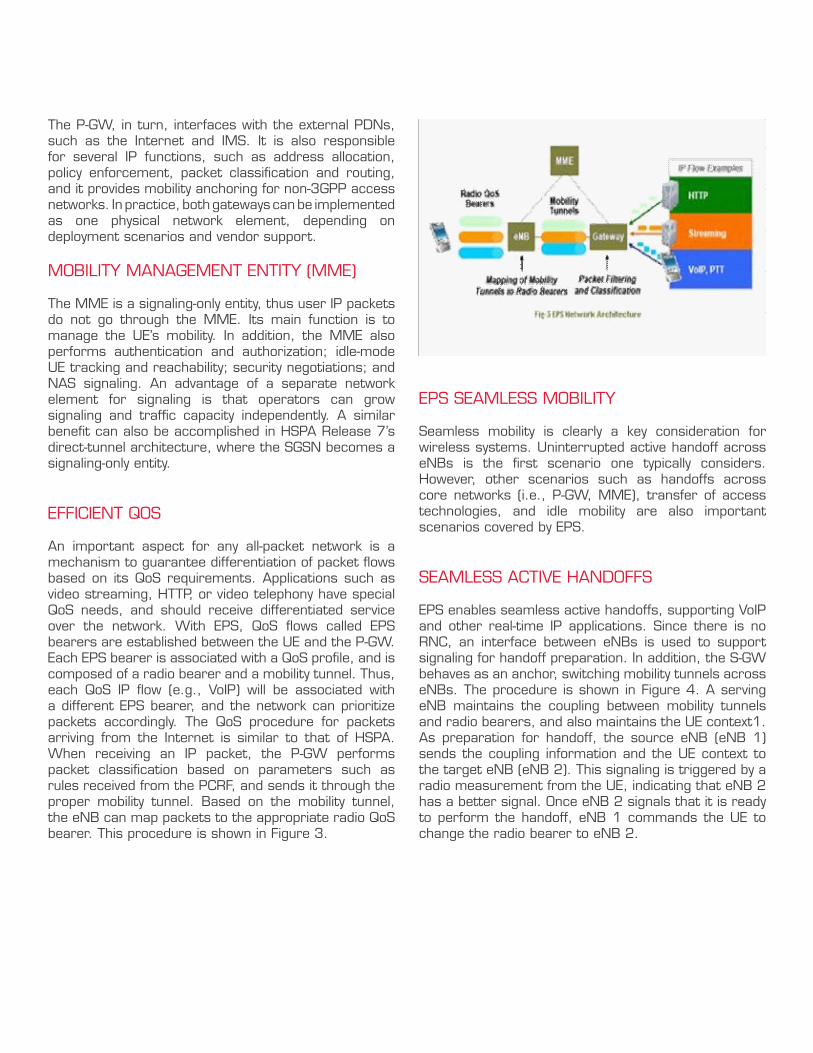
The P-GW, in turn, interfaces with the external PDNs, such as the Internet and IMS. It is also responsible for several IP functions, such as address allocation, policy enforcement, packet classification and routing, and it provides mobility anchoring for non-3GPP access networks. In practice, both gateways can be implemented as one physical network element, depending on deployment scenarios and vendor support.
MOBILITY MANAGEMENT ENTITY (MME)
The MME is a signaling-only entity, thus user IP packets do not go through the MME. Its main function is to manage the UE’s mobility. In addition, the MME also performs authentication and authorization; idle-mode UE tracking and reachability; security negotiations; and NAS signaling. An advantage of a separate network element for signaling is that operators can grow signaling and traffic capacity independently. A similar benefit can also be accomplished in HSPA Release 7’s direct-tunnel architecture, where the SGSN becomes a signaling-only entity.
EFFICIENT QOS
An important aspect for any all-packet network is a mechanism to guarantee differentiation of packet flows based on its QoS requirements. Applications such as video streaming, HTTP, or video telephony have special QoS needs, and should receive differentiated service over the network. With EPS, QoS flows called EPS bearers are established between the UE and the P-GW. Each EPS bearer is associated with a QoS profile, and is composed of a radio bearer and a mobility tunnel. Thus, each QoS IP flow (e.g., VoIP) will be associated with a different EPS bearer, and the network can prioritize packets accordingly. The QoS procedure for packets arriving from the Internet is similar to that of HSPA. When receiving an IP packet, the P-GW performs packet classification based on parameters such as rules received from the PCRF, and sends it through the proper mobility tunnel. Based on the mobility tunnel, the eNB can map packets to the appropriate radio QoS bearer. This procedure is shown in Figure 3.
EPS SEAMLESS MOBILITY
Seamless mobility is clearly a key consideration for wireless systems. Uninterrupted active handoff across eNBs is the first scenario one typically considers. However, other scenarios such as handoffs across core networks (i.e., P-GW, MME), transfer of access technologies, and idle mobility are also important scenarios covered by EPS.
SEAMLESS ACTIVE HANDOFFS
EPS enables seamless active handoffs, supporting VoIP and other real-time IP applications. Since there is no RNC, an interface between eNBs is used to support signaling for handoff preparation. In addition, the S-GW behaves as an anchor, switching mobility tunnels across eNBs. The procedure is shown in Figure 4. A serving eNB maintains the coupling between mobility tunnels and radio bearers, and also maintains the UE context1. As preparation for handoff, the source eNB (eNB 1) sends the coupling information and the UE context to the target eNB (eNB 2). This signaling is triggered by a radio measurement from the UE, indicating that eNB 2 has a better signal. Once eNB 2 signals that it is ready to perform the handoff, eNB 1 commands the UE to change the radio bearer to eNB 2.

EFFICIENT IDLE MOBILITY
An additional mobility aspect to consider with a new wireless core network is the mechanism to identify the approximate location of the UE when it is not active. EPS provides an efficient solution for idle mobility management. The basic idea is to associate a cluster of eNBs into tracking areas (TAs), as shown in Figure 6. The MME tracks which TA the UE is in, and if the UE moves to a different TA, the UE updates the MME with its new TA. When the EPS GW receives data for an idle UE, it will buffer the packets and query the MME for the UE’s location. Then the MME will page the UE in its most current TA. EPS includes a new concept, which is the ability of a UE to be registered in multiple TAs simultaneously. This allows the UE to minimize battery consumption during periods of high mobility, since it does not need to constantly update its location with the MME. It also minimizes the registration load on TA boundaries.
For the eNB handoff to complete, the S-GW must update its records with the new eNB that is serving the UE. For this phase, MME coordinates the mobility-tunnel switch from eNB 1 to eNB 2. MME triggers the
update at the S-GW, based on signaling received from eNB 2 indicating that the radio bearer was successfully transferred (Figure 5).
eNB 1
eNB 1
eNB
eNBeNB
eNB
eNB
eNB
eNB
MME
EPSGW
eNB 2
eNB 2
MMES-GW
Measurement Report1.
HO Request Context Transfer2.
HO Accept3.
HO Command4.
5. HO Complete
6. User Plane Update
7. Switch Tunnel
Fig - 4 Inter eNB handoff procedure (High Level)
Fig - 5 Mobility Tunnel Transfer during inter eNB Handoff
Fig - 6 Idle Mobility Tracking Areas
2
6
5
7
1
3
4
TA 1
TA 2

HETEROGENOUS NETWORK MOBILITY
LTE is envisioned as a complement to current HSPA/HSPA+ networks in locations that have high demand for data and enhanced broadband experience. Therefore, LTE access networks will co-exist with the widespread coverage of HSPA/HSPA+ networks, thus requiring robust mechanisms to interoperate. For data interoperability, EPC will support interfaces between the existing SGSNs and the MME and S-GW, which will allow data handoffs. For voice-service continuity, 3GPP is also working on standardizing a voice-call continuity approach that will enable seamless operation between VoIP over LTE and circuit-switched voice over R99.
CONCLUSIONS
EPS provides operators with efficient and robust core network architecture to support all IP services for LTE, HSPA and non-3GPP access networks. Fundamentally, it is a flattened architecture that enables simplified network design while still supporting seamless mobility and advanced QoS mechanisms. Many of the typical RNC functions are incorporated into the eNB, and the EPS defines a control plane with a separate network element, the MME. QoS logical connections are established between the UE and the EPS GW, providing differentiation of IP flows throughout the whole
network, and meeting the requirements for low-latency applications. The principles and design are similar to the evolved HSPA architecture, providing operators with a smooth migration path for their 3GPP core networks.
REFERENCES
http://www.3gpp1.org/Highlights/LTE/LTE.htm•
www.ikr.uni-stuttgart.de/Content/itg/fg524/•Meetings/2006-09-29-Ulm/01-3GPP_LTE-SAE_Overview_Sep06.pdf
www.motorola.com/.../Service%20Providers/•Wireless%20Operators/LTE/_Document/Static%20Files/6833_MotDoc.pdf
www.ericsson.com/ericsson/corpinfo/•publications/review/2007_03/files/5_LTE_SAE.pdf
www.nokiasiemensnetworks.com/NR/•rdonlyres/E6AC2D3F-A876-465A-8535-A612F9B2D485/0/Direct_Tunnel_Data_Sheet.pdf

About Tech Mahindra
Tech Mahindra represents the connected world, offering innovative and customer-centric information technology services and solutions, enabling Enterprises, Associates and the Society to Rise™. We are a USD 2.7 billion company with 84,000 professionals across 49 countries, helping 540 global customers including Fortune 500 companies. Our Consulting, Enterprise and Telecom solutions, platforms and reusable assets connect across a number of technologies to derive tangible business value. We are part of the USD 16.2 billion Mahindra Group that employs more than 155,000 people in over 100 countries. The Group operates in the key industries that drive economic growth, enjoying a leadership position in tractors, utility vehicles, information technology and vacation ownership.
Contact us at www.techmahindra.com | [email protected]


