43
LTE Paging Process Greg Harman NT&C Radio GSDC Australia Version PA1 30th October 2008
| Date post: | 21-Aug-2015 |
| Category: |
Education |
| Upload: | prashant-sengar |
| View: | 27 times |
| Download: | 0 times |

LTE Paging Process
Greg HarmanNT&C Radio
GSDC Australia
Version PA130th October 2008

Ericsson Internal LTE Paging Process 2008-10-312
Introductory Comment
The information presented in this document is based upon the best available information at the time of writing
The 3GPP standards upon which this information is based are still being developed and are subject to change and update

Ericsson Internal LTE Paging Process 2008-10-313
LTE Requirements for Paging
Downlink Paging Control Channel (PCCH)– Transmits paging information to UEs, and– Notifies UEs of changes in System Information (SI) which will
require a reacquisition of SI.– The paging channel can also be used to notify the UEs of the
presence of EWTS (Earthquake and Tsunami Warning System) information
The paging channel is used to communicate with a UE when the network does not know the location cell of the UE.

Ericsson Internal LTE Paging Process 2008-10-314
Paging OverviewKey Aspects of Paging Process
The UEs used Discontinuous Receive (DRx) in idle mode in order to reduce battery life. DRX is configured via parameters sent in SIB2
UEs monitor the PDCCH channel at regular intervals (set by the DRxparameters) in order to check for the presence of a paging message.
If the PDCCH indicates that a paging message is transmitted in the subframe then the UE needs to demodulate the paging channel (PCH) to see if the paging message is directed to it.
Paging messages are sent to all eNode Bs in a Tracking Area. The same paging message is transmitted on each eNode B.

Ericsson Internal LTE Paging Process 2008-10-315
Core Network Initiated PagingOverview Description
UEs use DRx when in idle mode in order to wake at regular intervals to check for paging messages.
The MME sends the PAGING message to each eNode B with cells belonging to the tracking area(s) in which the UE is registered.
Each eNode B can contain cells belonging to different tracking areas, whereas each cell can only belong to one TA.
The paging response back to the MME is initiated on NAS layer and is sent by the eNB based on NAS-level routing information.
The MME can send the paging message to one or many TAs.

Ericsson Internal LTE Paging Process 2008-10-316
LTE PagingInitial Context Setup The MME initiates a paging message which is
sent to all eNode Bs in a tracking area(s)
UEs use the Random Access procedure to initiate access to the serving cell
NAS messaging continues in order to set up the call

Ericsson Internal LTE Paging Process 2008-10-317
Tracking Area ReportingUE Behaviour
Tracking Area registrationIn the UE, the AS shall report tracking area information to the NAS. If the UE reads more than one PLMN identity in the current cell, the UE shall report the found PLMN identities that make the cell suitable in the tracking area information to NAS.The non-access part of the location registration process is uses the same processes as WCDMA [Specified in 3GPP TS 23.122]Actions for the UE AS upon reception of Location Registration reject are specified in [3GPP TS 22.011] and [3GPP TS 24.301].
From: 3GPP TS36.304 User Equipment (UE) procedures in idle mode

Ericsson Internal LTE Paging Process 2008-10-318
RAN SharingUp To 6 PLMNs – 1 Tracking Area Code
E-UTRAN can support RAN sharing based on support for multi-to-multi relationship between eNode Bs and EPC nodes. If the RAN is shared by multiple operators, the system information broadcasted in each shared cell contains the PLMN-id of each operator (up to 6) and a single tracking area code (TAC) valid within all the PLMNs sharing the RAN resources.The UE will read up to 6 PLMN-ids and select one of the PLMN-ids at initial attachment and to indicate this PLMN-id to the E-UTRAN in subsequent instances of the Random Access procedures.The eNode B selects an appropriate MME for the PLMN indicated by the UE. Once attached to an MME, the UE shall be able to indicate the allocated MME in subsequent instances of the Random Access procedures.

Ericsson Internal LTE Paging Process 2008-10-319
Defining TACParameter Definition of Tracking Area Code
ManagedElement+-ENodeBFunction
+-EUtranCellFDD
tac { 0..16777215 } – Tracking Area Code for the EUtran Cell. – Mandatory– Resolution: 1– Takes effect: Create object.
ManagedElement+-ENodeBFunction
+-TermPointToMme
struct TrackingAreaIdentity (TAI)
This element is used to uniquely identify a Tracking Area. TAI consist of MCC(3 digits MSB), MNC(2 or 3 digits) and TAC(3 digits LSB).
Takes effect: Create object.This attribute may only be changed by Ericsson personnel.
References from: TermPointToMme which Models the MME termination point of an S1 link between the RBS and the MME node.
mcc = 1 {long 0..999 } The MCC part of a PLMN identity used in the radio network. mnc = 1 {long 0..999 } The MNC part of a PLMN identity used in the radio network. mncLength = 2 {long 2..3 } The length of the MNC part of a PLMN identity used in the radio network. tac = 1 {long 0..16777215 } The TAC part of a Tracking Area identity used in the radio network.

Ericsson Internal LTE Paging Process 2008-10-3110
Idle Mode DRXThe UE may use Discontinuous Reception (DRX) in idle mode in order to reduce power consumption and subsequently increase battery life.
Parameters are transmitted on the overhead channel SIB2 which are used by the UE to calculate when to wake to monitor the Paging channel.
– One Paging Occasion (PO) is a subframe where there may be P-RNTI transmitted on PDCCH addressing the paging message.
– One Paging Frame (PF) is one Radio Frame, which may contain one or multiple Paging Occasion(s).
When DRX is used the UE needs only to monitor one P-RNTI per DRX cycle.
subframeDRX cycle
subframe
UE receiver circuitry switched off
UE monitors PDCCH channel at the start of the subframe to see if
a paging message is included
If the UE detects a P-RNTI value coded with the CRC of the PDCCH then it will decode the PDSCH to see if the paging
message is intended for itPaging opportunities

Ericsson Internal LTE Paging Process 2008-10-3111
Discontinuous ReceiveParameters in SIB2
Two parameters are transmitted in SIB2 which allow UEs to calculate the DRx period and determine when to wake up to monitor for paging messages.
nB• The parameter nB is used to derive the number of subframes used for paging within
each radio frame.• Valid values of nB are 4T, 2T, T, 1/2T, 1/4T, 1/8T, 1/16T, 1/32T
defaultPagingCycle• Default paging cycle, referred to as ‘T’. T indicates the number of radio frames in the
paging cycle. Valid values are 32, 64, 128, 256 radio frames.• The time between paging messages for each UE can be calculated (= T x 10 msec)• The UE specific DRX parameter, if allocated and having shorter DRX than T, shall
override T. UE specific DRX is FFS.
PCCH Configuration- Part of SIB2

Ericsson Internal LTE Paging Process 2008-10-3112
Discontinuous ReceiveDetermining Paging Subframe for UE to Monitor
PF is the radio frame number in which the UE shall monitor for PCCHPO is the subframe number within the PF that the UE must monitor
PF = SFN mod T= (T div N)*(UE_ID mod N)
PO can be determined by calculating the index value i_s which points to an table: i_s = (UE_ID/N) mod Ns
The following Parameters are used for the calculation of the PF and i_s:– T: 32, 64, 128, 256 radio frames. – nB: 4T, 2T, T, 1/2T, 1/4T, 1/8T, 1/16T, 1/32T. – N: min(T,nB)– Ns: max(1,nB/T)– UE_ID: IMSI mod1024.
95404
N/AN/A942
N/AN/AN/A91
i_s=3i_s=2i_s=1i_s=0Ns

Ericsson Internal LTE Paging Process 2008-10-3113
Parameter ImpactAffects on System Capacity
The parameter T (defaultPagingCycle) indicates the time between paging message opportunities for individual UE.
The parameter nB is used to derive the number of subframes used for paging within each radio frame.
A setting of nB=4 will result is 4 subframes being used for paging in each radio frame, whilst a setting of 1/32 will result in one out of every 32 radio frames having RBs set aside for paging.
The trade-off is the number of UEs that can be paged in the given period based on the max number of UEs messages that can fit into each PO

Ericsson Internal LTE Paging Process 2008-10-3114
Discontinuous ReceiveUpdating System Information Values
System Information DRX parameters stored in the UE shall be updated locally in the UE whenever the DRX parameter values are changed in SIB2.
If the UE has no IMSI, for instance when making an emergency call without USIM, the UE shall use as default identity UE_ID = 0 in the PF and i_s formulas above.

Ericsson Internal LTE Paging Process 2008-10-3115
Paging ChannelLogical & Transport Channels
Paging Control Channel (PCCH)Transfers paging information and system information change notifications. This channel is used for paging when the network does not know the location cell of the UE.
Paging Channel (PCH) characterised by:- support for UE discontinuous reception (DRX) to
enable UE power saving- requirement to be broadcast in the entire
coverage area of the cell- mapped to the PDSCH physical channel
TS36.300 Overall Description
Mapping between downlink transport channels and downlink physical channels
BCCHPCCH CCCH DCCH DTCH MCCH MTCH
BCHPCH
DL-SCH MCH
DownlinkLogical channels
DownlinkTransport channels
DownlinkPhysical channels
PBCH PDSCH PMCHPDCCH

Ericsson Internal LTE Paging Process 2008-10-3116
LTE PagingPhysical Layer Aspects
For LTE, paging relies on the PDCCH, monitored at predefined time instants according to a DRX cycle. No separate physical-layer paging indicator channel is used as the potential power savings are very small due to the short duration of PDCCH transmission, which is at most three OFDM symbols.If the terminal detects a paging message identity (P-RNTI) on the PDCCH, it demodulates and decodes the PDCCH and forwards the decoded paging transport channel (PCH) data to the MAC layer.The PCH transport block contains the exact identity of the terminal being paged.A terminal not finding its identity on the detected PCH will discard the information and sleep according to the DRX cycle.No ACK/NAK signaling is used and consequently HARQ with soft combining is not used for paging messages.

Ericsson Internal LTE Paging Process 2008-10-3117
RRC LayerUE Paging Behaviour
Upon receiving the Paging message, the UE shall:
1> If in RRC_IDLE, for each of the Paging records included in the Paging message:2> If the ue-identity included in the pagingRecordList matches one of the UE identities
allocated by upper layers:3> forward the ue-Identity, the cn-Domain and the pagingCause to the upper layers.
1> If the systemInfoModification is included:2> re-acquire the required system information using the system information acquisition
procedure as specified in 5.2.2.
1> If the etws-PrimaryNotificationIndication is included and the UE is ETWS capable:2> re-acquire SystemInformationBlockType1 immediately, i.e., without waiting until the next
system information modification boundary;2> acquire SystemInformationBlockType10;2> if the schedulingInformation indicates that SystemInformationBlockType11 is present:3> acquire SystemInformationBlockType11;
3GPP TS 36.331

Ericsson Internal LTE Paging Process 2008-10-3118
RRC Paging MessagePaging Message Contents
PagingThe Paging message is used for the notification of one or more UEs.Logical channel: PCCHDirection: E-UTRAN → UE
Paging message
Paging ::= SEQUENCE {pagingRecordList PagingRecordList OPTIONALPagingRecordList ::= SEQUENCE (SIZE (1..maxPageRec[=16])) OF {
ue-Identity PagingUE-Identity {S-TMSI (40 bits) or IMSI (24 to 64 bits)}cn-Domain ENUMERATED {ps or cs (1 bit)},pagingCause PagingCause Details FFS (? Bits),
}systemInfoModification ENUMERATED {true or false} OPTIONALetws-PrimaryNotificationIndication ENUMERATED {true or false} OPTIONALnonCriticalExtension SEQUENCE {} OPTIONAL
}

Ericsson Internal LTE Paging Process 2008-10-3119
IMSI CompositionSame Spec as GSM & WCDMA
Composition of IMSIIMSI is composed of three parts:1) Mobile Country Code (MCC) consisting of three digits. The MCC identifies uniquely the country of domicile of the mobile subscriber;2) Mobile Network Code (MNC) consisting of two or three digits for GSM/UMTS applications. The MNC identifies the home PLMN of the mobile subscriber. The length of the MNC (two or three digits) depends on the value of the MCC. 3) Mobile Subscriber Identification Number (MSIN) identifying the mobile subscriber within a PLMN.
Allocation principlesIMSI shall consist of decimal digits (0 through 9) only.The number of digits in IMSI shall not exceed 15.The allocation of Mobile Country Codes (MCCs) is administered by the ITU-T. The current allocation is given in the COMPLEMENT TO ITU-T RECOMMENDATION E.212 [44].The allocation of National Mobile Subscriber Identity (NMSI) is the responsibility of each administration.If more than one PLMN exists in a country, the same Mobile Network Code should not be assigned to more than one PLMN.The allocation of IMSIs should be such that not more than the digits MCC + MNC of the IMSI have to be analysed in a foreign PLMN for information transfer.
MCC
Not more than 15 digits
3 digits 2 or 3 digitsMNC MSIN
NMSI
IMSI
TS 23.003

Ericsson Internal LTE Paging Process 2008-10-3120
S-TMSI CompositionSAE-Temporary Mobile Subscriber Identity
S-TMSI information elementS-TMSI ::= SEQUENCE {
mmec MMEC ::= BIT STRING (SIZE (8)), identifies MME in MME Group in PLMN
m-TMSI BIT STRING (SIZE (32))}
Since the TMSI has only local significance (i.e. within a VLR and the area controlled by a VLR, or within an SGSN and the area controlled by an SGSN, or within an MME and the area controlled by an MME), the structure and coding of it can be chosen by agreement between operator and manufacturer in order to meet local needs.
The TMSI consists of 4 octets. It can be coded using a full hexadecimal representation.
In order to avoid double allocation of TMSIs after a restart of an allocating node, some part of the TMSI may be related to the time when it was allocated or contain a bit field which is changed when the allocating node has recovered from the restart.

Ericsson Internal LTE Paging Process 2008-10-3121
System Information ChangeRole of Paging Channel
The MIB is mapped on the BCCH and carried on BCH while all other SI messages are mapped on the BCCH and dynamically carried on DL-SCH where they can be identified through the SI-RNTI (System Information RNTI). Both the MIB and SIB1 use a fixed schedule with a periodicity of 40 and 80 ms respectively while the scheduling of other SI messages is flexible and indicated by SIB1.
The eNB may schedule DL-SCH transmissions concerning logical channels other than BCCH in the same subframe as used for BCCH. The minimum UE capability restricts the BCCH mapped to DL-SCH e.g. regarding the maximum rate.
The Paging message is used to inform UEs in RRC_IDLE and UEs in RRC_CONNECTED about a system information change.
System information may also be provided to the UE by means of dedicated signalling e.g. upon handover.

Ericsson Internal LTE Paging Process 2008-10-3122
System InformationCell Information Broadcast on SIB1
Tracking Area identity (TAI):This is the identity used to identify tracking areas. The Tracking Area Identity is constructed from the MCC (Mobile Country Code),MNC (Mobile Network Code) and TAC (Tracking Area Code).
The following identities are broadcast in every E-UTRAN cell:a) E-UTRAN Cell Identifier:
– Uniquely identifying the cell within a PLMN.b) Tracking Area identity:
– Tracking Area this cell belongs to.c) One or more PLMNs:
– PLMN (s) for which this cell is providing radio access.
Ericsson Internal LTE Paging Process 2008-10-3123
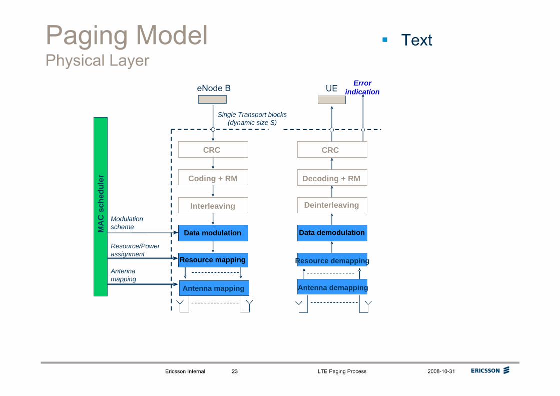
Paging ModelPhysical Layer
Text
CRC
Resource mapping
Coding + RM
Data modulation
Interleaving
Single Transport blocks(dynamic size S)
eNode B
Resource/Powerassignment
Modulationscheme
Antennamapping
Antenna mapping
CRC
Resource demapping
Decoding + RM
Deinterleaving
UE
Antenna demapping
Error indication
Data demodulationMA
C s
ched
uler

Ericsson Internal LTE Paging Process 2008-10-3124
Paging ModelPhysical Layer Description
The physical-layer model for PCH transmission is described based on the corresponding PCH physical-layer-processing chain. Processing steps that are relevant for the physical-layer model, e.g. in the sense that they are configurable by higher layers, are highlighted in blue on the figure.
Higher-layer data passed to/from the physical layerA single transport block per TTI.CRC and transport-block-error indicationTransport-block-error indication delivered to higher layers.FEC and rate matchingChannel coding rate is implicitly given by the combination of transport block size, modulation scheme and resource assignment;No PCH Hybrid ARQ, i.e. no higher-layer control of redundancy version.InterleavingNo control of interleaving by higher layers.Data modulationModulation scheme is decided by MAC Scheduler.Mapping to physical resourceL2 controlled resource assignment;Possible support of dynamic transport format and resource allocation.Multi-antenna processingMAC Scheduler partly configures mapping from assigned resource blocks to the available number of antenna ports.Support for Hybrid-ARQ-related signallingNo Hybrid ARQ.

Ericsson Internal LTE Paging Process 2008-10-3125
UE PCCH MonitoringSteps Undertaken by the UE to Detect Paging Messages
The UE undertakes the following steps when monitoring the paging channel
1. The UE activates its receiver as required for the DRX cycle2. The UE monitors the PCFICH channel to detect the number
of OFDM symbols in the subframe containing PDCCH information
3. The UE undertakes blind decoding of the PDCCH to determine where paging data is included in the subframe. It does this by looking for the scrambling of P-RNTI with the CRC of DCI messages
4. If there is a paging message the UE decodes the data included in the appropriate RBs to look for it’s own identifier (IMSI or S-TMSI)

Ericsson Internal LTE Paging Process 2008-10-3126
Reading PCFICHIndicates the Number of Symbols for PDCCH
The PCFICH is used to indicate the number of OFDM symbols used for PDCCH control signalling in the current subframe.
If the PCFICH is not correctly decoded, the UE will not know where to find the control channels, nor where the data region starts
The target error rate of the PCFICH is an implementation issue, although 1% is commonly assumed in 3GPP.
Two bits of information, corresponding to the PDCCH region size are coded into a 32-bit long sequence using a rate-1/16 simplex code. The coded bits are scrambled, QPSK-modulated and mapped to 16 resource elements.
– For NDLRB > 10 valid values are 1, 2 or 3 OFDM symbols for PDCCH
– For NDLRB ≤ 10 valid values are 2, 3 or 4 OFDM symbols for PDCCH
To avoid inter-cell PCFICH collisions, the location of the four groups in the frequency domain are evenly spaced with the starting position dependant on the physical-layer cell identity.

Ericsson Internal LTE Paging Process 2008-10-3127
PCFICHFormat & Coding
2, 3 or 4≤ 10
1, 2 or 3> 10
# PDCCHSymbols
4
4
4
432 bits
32 bits
Scrambling
16 symbols
QPSK modulation
2 bits
Rate 1/16 block code
PCFICHPDCCH
PDSCH
DLRBN
NB: 1 option reserved

Ericsson Internal LTE Paging Process 2008-10-3128
Downlink Control Information (DCI)Signalling Overhead RB allocations to the UE on PDCCH
There are a number of predefined DCI formats used on the PDCCH to signal RB assignments to UEsThe following DCI formats are applicable to overhead messages containing SI, Paging and RA information
– Format 1A – Signals 2 or 3 PRBs for one PDSCH codeword– Format 1C – Signals multiple PRBs, used exclusively for overhead
messagesThe DCI messages are transmitted in multiples of 1, 2, 4 or 8 CCE (Control Channel Elements) where each CCE corresponds to 36 REs (72 bits)
– UE specific channels aggregate 1,2 4 or 8 CCEs– Common control channels aggregate 4 or 8 CCEs
Limiting the number of CCE options per DCI message allows the UEto undertake blind decoding of the PDCCH (ie it has no pre-knowledge of the coding format of the PDCCH)

Ericsson Internal LTE Paging Process 2008-10-3129
RNTI ValuesPaging RNTI Value
SI-RNTIFFFF
P-RNTIFFFE
Reserved for future useFFF3-FFFC
C-RNTI, Semi-Persistent Scheduling C-RNTI, Temporary C-RNTI, TPC-PUCCH-RNTI and TPC-PUSCH-RNTI
003C-FFF2000A-FFF2
RA-RNTI0000-003B0000-0009
TDDFDD
RNTIValue (hexa-decimal)
For overhead messages the 16 bit CRC of the PDCCH is scrambled by the following values
• Random Access Message 2 RA-RNTI,• Paging message P-RNTI, or• System information SI-RNTI
The UEs undertake a blind detection of the PDCCH based on a limited number of coding options (Resource Elements - REs) and then use the scrambled CRC to detect the presence of the overhead message

Ericsson Internal LTE Paging Process 2008-10-3130
DCI Format 1CMessage Contents
DCI format 1C is used for very compact scheduling of one PDSCH codeword.
The following information is transmitted by means of the DCI format 1C:
– 1 bit indicates the gap value for Distributed Virtual Resource Block (VRB) assignments
– RIV bits indicate the Resource Indication Value that uniquely identifies start position and length of the RB assignment for the PDSCH
The number of bits required depends on the number of DL RBs and the Step size (Nstep) which is the minimum RB allocationFor < 50 RBs, Nstep = 2 otherwise Nstep = 4
– 5 bits indicate the Transport Block Size index (ITBS)
810077565062551536
RIVDLRBN

Ericsson Internal LTE Paging Process 2008-10-3131
Resource Indication ValueRIV – Uniquely Mapping Start and Length of Overhead Message
PRBs Assigned for PDSCH
2
4
1
5
3
0
543210RIV
Below is an example of RIV for a cell with a 1.4 MHz bandwidth (6 RBs).
For DCI format 1C RBs are allocated in contiguous blocks with a step size (Nstep) of 2 RBs
• leading to 6 valid combinations RB assignments.
In the example 3 bits are required in the PDCCH Format 1C message to uniquely identify the valid starting RBs and length combinations

Ericsson Internal LTE Paging Process 2008-10-3132
DCI Format 1CTransport Block Sizes
The table shows the proposed TBS for DCI Format 1C which will be used by SI, Paging and RA 2 messages
The numbers of Res available for in each RB is shown below assuming 2 Txantennas and different sizes of PDCCH
– 1 PDCCH = 144 REs = 288 bits– 2 PDCCH = 132 REs = 264 bits– 3 PDCCH = 120 REs = 240 bits
To get a coding rate of 1/16, to match the PCFICH coverage, using 4 RBs, 1 PDCCH and 2 Tx antennas
= 4 x 288 = 1152/16 = 72→ ITBS = 2 17363148815
16083039214
14802933613
13842832812
12882729611
12242628010
1128252569
1064242248
1000232087
904221766
840211445
776201364
696191203
63218722
60017561
55216400
TBSITBSTBSITBS
Based upon draft CR R1-084042For document TS36.213

Ericsson Internal LTE Paging Process 2008-10-3133
DCI Format 1AMessage Contents
DCI format 1A is used for the compact scheduling of one PDSCH codeword.
The following information is transmitted by means of the DCI format 1A:– 1 bit for the format Flag for PDSCH allocation
Used to indicate NRB assignment for RA-RNTI, P-RNTI, or SI-RNTI– 1 bit to indicate Localized/Distributed VRB assignment – N bits for the Resource block assignment (depends on NDL
RB)– 5 bits for the Modulation and coding scheme– HARQ process number – 3 bits (FDD) , 4 bits (TDD)– 1 bit for New data indicator (indicates gap size for overhead messages) – 2 bits for Redundancy version – 2 bits for TPC command for PUCCH – 2 bits for Downlink Assignment Index (TDD only)
Zeros are used to pad out the message to fit the correct block sizeSome of these fields are reserved when the CRC is scrambled with a RA-RNTI, P-RNTI, or SI-RNTI

Ericsson Internal LTE Paging Process 2008-10-3134
Transport Block SizesRA-RNTI, P-RNTI and SI-RNTI – DCI Format 1C
NPRBITBS
32
4562969
3922568
3282247
2561766
2241445
2081204
1761043
144722
88561
56320
Overhead channels are modulated using QPSK modulation.
In the standard the transport block sizes are variable which allows for different levels of coding redundancy.
– In practice the TBS will be hard coded so that the coverage of the overhead messages matches that of the PDCCH message
The overhead messages can take up 2 or 3 physical resource blocks (PRBs) depending on the type of PDCCH message
– The PDCCH message is used to indicate the number of PRBs
Each PRB has 12 subcarriers x (up to) 13 symbols less RS allocations
Number of bits in the transport block. CRC added to this and CRC is scrambled with RNTI value
Number of RBs
More coderedundancy
=More
coverage
Less coderedundancy
=More data in
message(eg more UEs
paged/message) but less coverage

CORE NETWORKCOMPONENT
S1AP PROTOCOL

Ericsson Internal LTE Paging Process 2008-10-3136
The Initial Context Setup procedure, which is initiated by the MME, establishes the necessary overall initial UE context in the eNode B in the case of an Idle-to Active transition (eg. UE terminating call).
The Initial Context Setup procedure comprises the following steps:– The MME initiates the Initial Context Setup procedure by sending INITIAL
CONTEXT SETUP REQUEST to the eNode B. This message may include general UE Context (e.g. security context, roaming restrictions, UE capability information, UE S1 signalling connection ID, etc.), EPS bearer context (Serving GW TEID, QoS information), and may be piggy-backed with the corresponding NAS message.
– Upon receipt of INITIAL CONTEXT SETUP REQUEST, the eNode B setup the context of the associated UE, and perform the necessary RRC signalling towards the UE, e.g. Radio Bearer Setup procedure.
– The eNode B responds with INITIAL CONTEXT SETUP COMPLETE to inform a successful operation, and with INITIAL CONTEXT SETUP FAILURE to inform an unsuccessful operation.
LTE PagingInitial Context Setup Description

Ericsson Internal LTE Paging Process 2008-10-3137
TS36.300Comments on S1 Paging Function
Sect 19.2.1.1 S1 Paging function
The paging function supports the sending of paging requests to all cells of the TA(s) the UE is registered. Paging requests are sent to the relevant eNBs according to the mobility information kept in the UE’s MM context in the serving MME.
eNB MME
[S1AP] PAGING
Paging Response (NAS means)
Paging Procedure
The MME initiates the paging procedure by sending the PAGING message to each eNB with cells belonging to the tracking area(s) in which the UE is registered. Each eNB can contain cells belonging to different tracking areas, whereas each cell can only belong to one TA.
The paging response back to the MME is initiated on NAS layer and is sent by the eNB based on NAS-level routing information.

Ericsson Internal LTE Paging Process 2008-10-3138
S1AP Paging ProcessOverview
The purpose of the Paging procedure is to enable the MME to page a UE in the specific eNode B.
The MME initiates the paging procedure by sending the PAGING message to the eNode B.
At the reception of the PAGING message, the eNode B shall perform paging of the UE in cells which belong to tracking areas as indicated in the List of TAIs IE. The Paging Cause IE shall be transferred transparently to the UE.
The Paging DRX IE may be included in the PAGING message, and if present the eNode B shall use it for calculating the paging occasions for the UE.
For each cell that belongs to any of the TA indicated in the List of TAIs IE, the eNode B shall generate one page on the radio interface.
3GPP TS 36.413 S1 Application Protocol (S1AP) V8.3.0 (2008-09)
PAGING
eNB MME

Ericsson Internal LTE Paging Process 2008-10-3139
S1AP Paging ProcessMessage Contents
This message is sent by the MME and is used to page a UE in one or several tracking areas.Direction: MME -> eNB
-PLMN (3 Octets) + Tracking Area Code (1 Octet)M>>TAI
ignoreEACH1 to < max no of TAI = FFS>>TAI List Item
ignoreYESList of TAIs
ignoreYESENUMERATED( Terminating Conversational Call, Terminating Streaming Call, Terminating Interactive Call, Terminating Background Call,Terminating Low Priority Signalling, ...,Terminating High Priority Signalling)
MPaging Cause
ignoreYESWill align with 36.331OPaging DRX
ignoreYESS-TMSI (5 Octets) or IMSI (3 .. 8 Octets)
MUE Paging ID
ignoreYESMUE Identity Index value
ignoreYESPaging, {Initiating Message, Successful Outcome, Unsuccessful Outcome, …}
MMessage Type
Assigned Criticality
CriticalityRangePresenceIE/Group Name

Ericsson Internal LTE Paging Process 2008-10-3140

Ericsson Internal LTE Paging Process 2008-10-3141
Discontinuous RxConcept
DRX Cycle: Specifies the periodic repetition of the On Duration followed by a possible period of inactivity.
DRX Inactivity Timer: Specifies the number of consecutive PDCCH-subframe(s) after successfully decoding a PDCCH indicating an initial UL or DL user data transmission for this UE.
DRX Retransmission Timer: Specifies the maximum number of consecutive PDCCH-subframe(s) for as soon as a DL retransmission is expected by the UE.
DRX Short Cycle Timer: This parameter specifies the number of consecutive subframe(s)the UE shall follow the short DRX cycle after the DRX Inactivity Timer has expired.
On Duration Timer: Specifies the number of consecutive PDCCH-subframe(s) at the beginning of a DRX Cycle.

Ericsson Internal LTE Paging Process 2008-10-3142
DRx TS36.321The UE may be configured by RRC with a DRX functionality that allows it to monitor the PDCCH discontinuously. DRX operation is based on a Long DRX cycle, a DRX Inactivity Timer, a HARQ RTT Timer, a DRX Retransmission Timer and optionally a Short DRX Cycle and a DRX Short Cycle Timer, all defined in subclause 3.1.When a DRX cycle is configured, the Active Time includes the time while: - the On Duration Timer or the DRX Inactivity Timer or a DRX Retransmission Timer or the Contention Resolution Timer (as described in subclause 5.1.5) is running; or- a Scheduling Request is pending (as described in subclause 5.4.4); or- an uplink grant for a pending HARQ retransmission can occur; or- a PDCCH indicating a new transmission addressed to the C-RNTI or Temporary C-RNTI of the UE has not been received after successful reception of a Random Access Response (as described in subclause 5.1.4).When DRX is configured, the UE shall for each subframe:- If the Short DRX Cycle is used and [(SFN * 10) + subframe number] modulo (Short DRX Cycle) = DRX Start Offset; or- if the Long DRX Cycle is used and [(SFN * 10) + subframe number] modulo (Long DRX Cycle) = DRX Start Offset:- start the On Duration Timer.- if a HARQ RTT Timer expires in this subframe and the data in the soft buffer of the corresponding HARQ process was not successfully decoded:- start the DRX Retransmission Timer for the corresponding HARQ process.- if a DRX Command MAC control element is received:- stop the On Duration Timer;- stop the DRX Inactivity Timer.- if the DRX Inactivity Timer expires or a DRX Command MAC control element is received in this subframe:- if the short DRX cycle is configured:- start or restart the DRX Short Cycle Timer;- use the Short DRX Cycle.- else:- use the Long DRX cycle.- if the DRX Short Cycle Timer expires in this subframe:- use the long DRX cycle.- during the Active Time, for a PDCCH-subframe except if the subframe is required for uplink transmission for half-duplex FDD UE operation and except if the subframe is part of a configured measurement gap:- monitor the PDCCH;- if the PDCCH indicates a DL transmission or if a DL assignment has been configured for this subframe:- start the HARQ RTT Timer for the corresponding HARQ process;- stop the DRX Retransmission Timer for the corresponding HARQ process.- if the PDCCH indicates a new transmission (DL or UL):- start or restart the DRX Inactivity Timer.- when not in active time, CQI/SRS/PMI/RI shall not be reported.Regardless of whether the UE is monitoring PDCCH or not the UE receives and transmits HARQ feedback when such is expected.

Ericsson Internal LTE Paging Process 2008-10-3143
DRX in RRC_CONNECTED In order to enable reasonable UE battery consumption, DRX in E-UTRAN is characterised by the following:
Per UE mechanism (as opposed to per radio bearer);No RRC or MAC substate to distinguish between different levels of DRX;Available DRX values are controlled by the network and start from non-DRX up to x seconds. Value x may be as long as the paging DRX used in ECM-IDLE;Measurement requirement and reporting criteria can differ according to the length of the DRX interval i.e. long DRX intervals may experience more relaxed requirements;Irrespective of DRX, UE may use first available RACH opportunity to send an UL measurement report;Immediately after sending a measurement report, the UE may change its DRX. This mechanism would be pre-configured by the eNB;HARQ operation related to data transmission is independent of DRX operation and the UE wakes up to read the PDCCH for possible retransmissions and/or ACK/NAK signalling regardless of DRX In the downlink, a timer is used to limit the time the UE stays awake awaiting for a retransmission;When DRX is configured, the UE may be further configured with an "on-duration" timer during which time the UE monitors the L1/L2 control channels for possible allocations;When DRX is configured, periodic CQI reports can only be sent by the UE during the “active-time”. RRC can further restrict periodic CQI reports so that they are only sent during the on-duration;A timer in the UE is used to detect need for obtaining timing advance.
The following definitions apply to DRX in E-UTRAN:on-duration: duration in downlink subframes that the UE waits for, after waking up from DRX, to receive PDCCHs. If the UE successfully decodes a PDCCH, the UE stays awake and starts the inactivity timer;inactivity-timer: duration in downlink subframes that the UE waits to successfully decode a PDCCH, from the last successful decoding of a PDCCH, failing which it re-enters DRX. The UE shall restart the inactivity timer following a single successful decoding of a PDCCH for a first transmission only (i.e. not for retransmissions).active-time: total duration that the UE is awake. This includes the “on-duration” of the DRX cycle, the time UE is performing continuous reception while the inactivity timer has not expired and the time UE is performing continuous reception while waiting for a DL retransmission after one HARQ RTT. Based on the above the minimum active time is of length equal to on-duration, and the maximum is undefined (infinite);
Of the above parameters the on-duration and inactivity-timer are of fixed lengths, while the active-time is of varying lengths based on scheduling decision and UE decoding success. Only on-duration and inactivity-timer duration are signalled to the UE by the eNB:There is only one DRX configuration applied in the UE at any time;UE shall apply an on-duration on wake-up from DRX sleep;
NOTE: this is also applicable for the case where the UE has only one service (e.g. Real Time) that is being handled through the allocation of predefined resources; this allows for other signalling such as RRC to be sent during the remaining portion of the active time.New transmissions can only take place during the active-time (so that when the UE is waiting for one retransmission only, it does not have to be “awake” during the RTT).If PDCCH has not been successfully decoded during the on-duration, the UE shall follow the DRX configuration (i.e. the UE can enter DRX sleep if allowed by the DRX configuration):
– This applies also for the sub-frames where the UE has been allocated predefined resources.If it successfully decodes a PDCCH for a first transmission, the UE shall stay awake and start the inactivity timer (even if a PDCCH is successfully decoded in the sub-frames where the UE has also been allocated predefined resources) until a MAC control message tells the UE to re-enter DRX, or until the inactivity timer expires. In both cases, the DRX cycle that the UE follows after re-entering DRX is given by the following rules:
- If a short DRX cycle is configured; the UE first follows the short DRX cycle and after a longer period of inactivity the UE follows the long DRX cycle;- Else the UE follows the long DRX cycle directly.
TS36.300 Section 12


