User Manual Installation and Operation Instructions 2.1A-38020-B04 Form 403439 Subject to modificaitons Section - Q 3 Page - 19 Lubrication System QLS 401 6141b03 6093b04 U.S. Patent-No. 6,244,387, German Registration Design No. 29923765.6 810-55374-1
Transcript
User ManualInstallation and Operation Instructions
2.1A-38020-B04Form 403439
Sub
ject
to
mod
ifica
itons
Section - Q 3 Page - 19
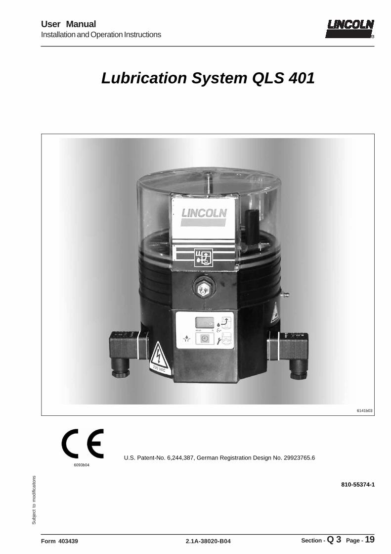
Lubrication System QLS 401
6141b03
6093b04
U.S. Patent-No. 6,244,387, German Registration Design No. 29923765.6
810-55374-1
Page 2 of 48
User ManualInstallation and Operation Instructions
2.1A-38020-B04 Form 403439
Sub
ject
to
mod
ifica
itons
All rights reserved. Any duplication of this Owner Manual, in its entirety or in part, by whatever means is prohibited without the prior consent in writing of Lincoln GmbH & CO. KG. Subject to modifications without prior notification.
User ManualInstallation and Operation Instructions
2.1A-38020-B04Form 403439
Sub
ject
to
mod
ifica
itons
Table of Content
Page
Introduction ........................................................................ 4 Explanation of Symbols Used ............................................ 4 User’s Responsibility ......................................................... 4 Environmental Protection .................................................. 4 Service .............................................................................. 4 Safety Instructions ............................................................. 5 Appropriate Use ................................................................ 5 Misuse ............................................................................... 5 General Safety Instructions ............................................... 5 Regulation for Prevention of Accidents ............................. 5 Operation, Repair and Maintenance .................................. 5 Repair .......................................................................... 5 Operation / Maintenance .............................................. 6 Disposal ............................................................................. 6 Exclusion of Liability .......................................................... 6 Installation ......................................................................... 6 Installation Instructions ...................................................... 7 Pump ................................................................................. 7 SSV Divider Block ............................................................. 7 Cross-porting of the SSV Divider Blocks ........................... 7 Single Output ............................................................... 7 Double and Multiple Outputs ........................................ 7 Check valve ................................................................. 7 Direct (internal) feedback feature ...................................... 8 Lubrication Points .............................................................. 9 Installing Zerk-Locks onto Grease Fittings ........................ 9 Connection of Feed Lines ................................................ 10 Filling of reservoir ............................................................ 10 Electrical connection ....................................................... 10 Option for metric fittings ................................................... 11 Description ...................................................................... 12 Selection Guide ............................................................... 14 VDC ................................................................................. 14 VAC ................................................................................. 15
Page
Operation ......................................................................... 16 Pump ............................................................................... 16 Pressure Relief Valve ...................................................... 16 Pump Display Window ..................................................... 16 Monitoring time / Malfunction ........................................... 17 Reservoir empties ...................................................... 18 Operator keys of the keypad ............................................ 18 Additional lube cycle ................................................... 18 Reset of the pause time ............................................. 18 Acknowledging receipt of a malfunction ..................... 19 Display of the set pause time ..................................... 19 Changing to the different programming levels ............ 19 Monitoring relay ............................................................... 19 Setting and Operation .......................................................20 General ............................................................................ 20 Factory Settings ......................................................... 20 Operator keys ............................................................. 20 Display Mode ................................................................... 21 Operating Mode ............................................................... 22 Programming Mode ......................................................... 25 Maintenance, Repair and Tests ....................................... 29 Maintenance .................................................................... 29 To fill reservoir ............................................................ 29 First filling of a lubrication system ............................... 30 Repair .............................................................................. 30 Functional Test ................................................................ 30 Troubleshooting ............................................................... 31 Pump of the QLS 401 system .......................................... 31 SSV divider block ............................................................. 32 Technical Data.................................................................. 34 QLS 401, General ....................................................... 34 Electrical Data ............................................................ 34 Time Setting ............................................................... 34 Relay for Malfunction (Option) .................................... 34 Lines ........................................................................... 35 Tightening Torques .................................................... 35 Accessory Kits ............................................................ 35 Dimensions ...................................................................... 35 Pump .......................................................................... 35 SSV divider blocks ..................................................... 35 Electrical connection ........................................................ 36 Lubricants ........................................................................ 38 Lubricating greases for QuickLub systems ................. 39 Biodegradable greases .............................................. 39 Service Parts .................................................................... 40 Explosion view and Parts list with bottom mounted SSV divider block ................................... 40 Explosion view and Parts list with back mounted SSV divider block ..................................... 42 Declaration of conformity ................................................. 44
Page 4 of 48
User ManualInstallation and Operation Instructions
2.1A-38020-B04 Form 403439
Sub
ject
to
mod
ifica
itons
Introduction
Explanation of Symbols Used
The following description standards are used in this manual:
Safety Instructions
Structure of safety instructions: � Pictogram � Signal word � Danger text
- Danger note - How to avoid danger
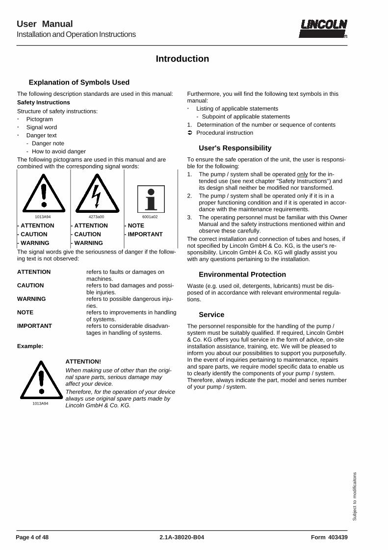
The following pictograms are used in this manual and are combined with the corresponding signal words:
1013A94
4273a00
6001a02
- ATTENTION - CAUTION - WARNING
- ATTENTION - CAUTION - WARNING
- NOTE - IMPORTANT
The signal words give the seriousness of danger if the follow-ing text is not observed: ATTENTION refers to faults or damages on
machines. CAUTION refers to bad damages and possi-
ble injuries. WARNING refers to possible dangerous inju-
ries. NOTE refers to improvements in handling
of systems. IMPORTANT refers to considerable disadvan-
tages in handling of systems. Example:
1013A94
ATTENTION!
When making use of other than the origi-nal spare parts, serious damage may affect your device. Therefore, for the operation of your device always use original spare parts made by Lincoln GmbH & Co. KG.
Furthermore, you will find the following text symbols in this manual: � Listing of applicable statements
- Subpoint of applicable statements 1. Determination of the number or sequence of contents � Procedural instruction
User's Responsibility
To ensure the safe operation of the unit, the user is responsi-ble for the following: 1. The pump / system shall be operated only for the in-
tended use (see next chapter "Safety Instructions") and its design shall neither be modified nor transformed.
2. The pump / system shall be operated only if it is in a proper functioning condition and if it is operated in accor-dance with the maintenance requirements.
3. The operating personnel must be familiar with this Owner Manual and the safety instructions mentioned within and observe these carefully.
The correct installation and connection of tubes and hoses, if not specified by Lincoln GmbH & Co. KG, is the user's re-sponsibility. Lincoln GmbH & Co. KG will gladly assist you with any questions pertaining to the installation.
Environmental Protection
Waste (e.g. used oil, detergents, lubricants) must be dis-posed of in accordance with relevant environmental regula-tions.
Service
The personnel responsible for the handling of the pump / system must be suitably qualified. If required, Lincoln GmbH & Co. KG offers you full service in the form of advice, on-site installation assistance, training, etc. We will be pleased to inform you about our possibilities to support you purposefully. In the event of inquiries pertaining to maintenance, repairs and spare parts, we require model specific data to enable us to clearly identify the components of your pump / system. Therefore, always indicate the part, model and series number of your pump / system.
Page 5 of 48
User ManualInstallation and Operation Instructions
2.1A-38020-B04Form 403439
Sub
ject
to
mod
ifica
itons
Safety Instructions
Appropriate Use
The lubrication system QLS 401 has been designed for initial and retrofit installation. It has been designed for: � the automatic lubrication of machines and systems
� the automatic lubrication of commercial vehicles and con-struction machines
� the automatic lubrication of hydraulically driven units and devices.
The lubrication system QLS 401 is able to deliver greases up to NLGI - class 2 or fluid greases of NLGI - class 000 or 00. � Use the QLS 401 exclusively to supply lubricants.
� The QLS 401 is adequate for intermittent operation only.
� The QLS 401 is adequate for feeding max. 18 lube points per lube cycle.
� Do not use QLS 401 with SSV divider block in bottom mounting position for mobile applications. Do not install the system with machines exposed to shock.
Misuse
Any use of the QLS 401 that is not expressly mentioned in this Owner Manual will be regarded as misuse. If the QLS 401 is used or operated in a different manner other than specified, any claim for warranty or liability will be null and void.
6001a02
NOTE
If personal injury or material damage occurs as a result of inappropriate opera-tion, e.g. if the safety instructions are ignored or resulting from an incorrect installation of the QLS 401, no claims or legal actions may be taken against Lincoln GmbH & Co. KG.
Regulations for Prevention of Accidents
To prevent accidents, observe all city, state and federal safety regulation of the country in which the product will be used.
General Safety Instructions
� Lubrication systems QLS 401
- are designed state-of-the-art.
- can be assembled for safe operation.
- must be filled regularly without air inclusions with clean lubricant recommended by the manufacturer (see page 40 ff).
General Safety Instructions, continuation
� Incorrect use may result in bearing damage caused by poor or over-lubrication.
� Do not over-pressurize reservoir when filling the pump. Refill QLS 401 pump with clean lubricant.
� Each outlet needed must be equipped with an appropriate check valve.
6001a02
IMPORTANT
Do not paint the pump. Before painting a machine or commercial vehicle, remove or cover the pump completely.
� Unauthorized modifications or changes to an installed system are not recommended and will void warranty. Any modifications must be subject to prior consultation with the manufacturer of the QLS 401.
Operation, Repair and Maintenance
1013A94
ATTENTION!
Malfunction because of dirt! When executing any maintenance or repair works on the QLS 401, ensure absolute cleanliness.
4273a00
CAUTION!
For pumps with 120 VAC and 230 VAC, switch off the power supply before be-ginning maintenance or repair work.
Repair
Repairs should only be performed by authorized personnel who are familiar with the instructions.
Operation with bayonet plug
4273a00
CAUTION!
If the protective-conductor terminal is not connected or interrupted, dangerous touch voltages may occur on the equipment!
Protective measures to be applied for the appropriate opera-tion with bayonet plugs: "Functional extra-low voltage with safe isolation" / "Protective Extra-Low Voltage" (PELV) Standards: EN60204 Part1:1992 / IEC 204-1:1992, modified DIN VDE 0100 Part (see page 39 and 40)
Page 6 of 48
User ManualInstallation and Operation Instructions
2.1A-38020-B04 Form 403439
Sub
ject
to
mod
ifica
itons
Safety Instructions, continuation
Operation, Repair and Maintenance, continuation
Operation/Maintenance
Lubrication systems QLS 401
� must operate with mounted pressure relief valve, only.
� must operate only with mounted or connected SSV divider blocks.
� must be filled regularly without air inclusions with clean lubricant recommended by the manufacturer.
� operates automatically. However, a regular check (ac-cording to the fixed lubrication intervals) should be made to ensure that lubricant is being dispensed from all lubri-cant points.
Repair
Repairs should only be performed by authorized personnel who are familiar with the instructions.
Disposal
Dispose of used or contaminated lubricants as well as of parts that were in touch with lubricant according to the legal regulations pertaining to environmental protection. Make sure to observe the safety data sheets of the lubricants used.
Exclusion of Liability
The manufacturer of the centralized lubrication system QLS 401 will not accept any liability for damages:
� caused by insufficient lubricant and irregular refilling of pump.
� due to the use of greases which are not or are only condi-tionally pumpable in centralized lubrication systems.
� caused by the use of contaminated lubricants.
� caused by an environmentally inadequate disposal of used or contaminated lubricants or parts that were in touch with lubricants.
� caused by unauthorized modification of system compo-nents.
� caused by the use of unapproved parts (voids the pump warranty).
Installation
6001a02
IMPORTANT
Do not remove, modify or alter any safety equipment already installed on the machine.
� If necessary, these devices may be removed temporarily during the in-stallation of the pump.
� The devices must be properly put back in place after the installation of the pump.
Installation, continutation
� Use only original spare parts or spare parts authorized by Lincoln.
� Keep the centralized lubrication system QLS 401 away from sources of heat. Observe the operating temperatures (see page 35, chapter "Technical Data")..
� Provide access to fill, clean and visually monitor the pump operation.
6001a02
IMPORTANT
Follow installation instructions of the OEM regarding minimum distances between the drilled holes and welding procedures.
4273a00
WARNING!
Failure to observe the safety instructions, e. g. touching electrically charged parts when the system is opened, or improper handling of the QLS 401 may cause serious injury or death. If the values specified in the Technical Data are exceeded, the device may overheat. It may damage the QLS 401 and thus impair the electric safety.
4273a00
CAUTION!
The QLS 401 may only be installed by qualified personnel. The connection (N/L/PE) of the supply voltage must be made according to VDE 0100 and VDE 0160. Install a protective and lock out device for isolating and disconnecting the QLS 401. Before beginning the installation work, disconnect the electrical supply.
4273a00
ATTENTION!
Consider residual ripple of max. ±5 % to connect pumps with direct current version (in relation to the operating voltage acc. to DIN 41755).
Page 7 of 48
User ManualInstallation and Operation Instructions
2.1A-38020-B04Form 403439
Sub
ject
to
mod
ifica
itons
Installation Instructions
Pump
Use drilling template to mark and drill mounting holes of the QLS 401. Drilling template and mounting bolts are included in the package.
SSV Divider Block
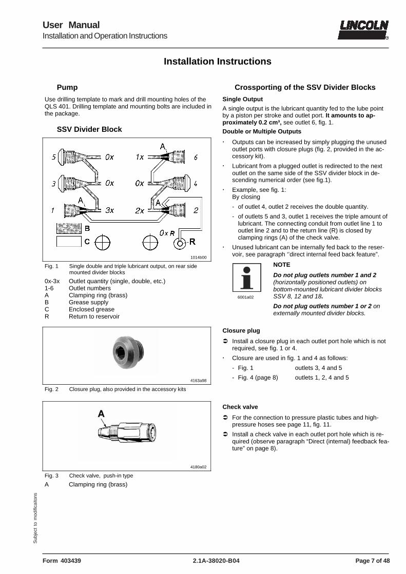
1014b00
Fig. 1 Single double and triple lubricant output, on rear side mounted divider blocks
0x-3x Outlet quantity (single, double, etc.) 1-6 Outlet numbers A Clamping ring (brass) B Grease supply C Enclosed grease R Return to reservoir
4163a98
Fig. 2 Closure plug, also provided in the accessory kits
Crossporting of the SSV Divider Blocks
Single Output
A single output is the lubricant quantity fed to the lube point by a piston per stroke and outlet port. It amounts to ap-proximately 0.2 cm³, see outlet 6, fig. 1.
Double or Multiple Outputs
� Outputs can be increased by simply plugging the unused outlet ports with closure plugs (fig. 2, provided in the ac-cessory kit).
� Lubricant from a plugged outlet is redirected to the next outlet on the same side of the SSV divider block in de-scending numerical order (see fig.1).
� Example, see fig. 1: By closing
- of outlet 4, outlet 2 receives the double quantity.
- of outlets 5 and 3, outlet 1 receives the triple amount of lubricant. The connecting conduit from outlet line 1 to outlet line 2 and to the return line (R) is closed by clamping rings (A) of the check valve.
� Unused lubricant can be internally fed back to the reser-voir, see paragraph ‘’direct internal feed back feature”.
6001a02
NOTE
Do not plug outlets number 1 and 2 (horizontally positioned outlets) on bottom-mounted lubricant divider blocks SSV 8, 12 and 18.
Do not plug outlets number 1 or 2 on externally mounted divider blocks.
Closure plug
� Install a closure plug in each outlet port hole which is not required, see fig. 1 or 4.
� Closure are used in fig. 1 and 4 as follows:
- Fig. 1 outlets 3, 4 and 5
- Fig. 4 (page 8) outlets 1, 2, 4 and 5
4180a02
Fig. 3 Check valve, push-in type
A Clamping ring (brass)
Check valve
� For the connection to pressure plastic tubes and high-pressure hoses see page 11, fig. 11.
� Install a check valve in each outlet port hole which is re-quired (observe paragraph “Direct (internal) feedback fea-ture” on page 8).
Page 8 of 48
User ManualInstallation and Operation Instructions
2.1A-38020-B04 Form 403439
Sub
ject
to
mod
ifica
itons
Installation Instructions, continuation
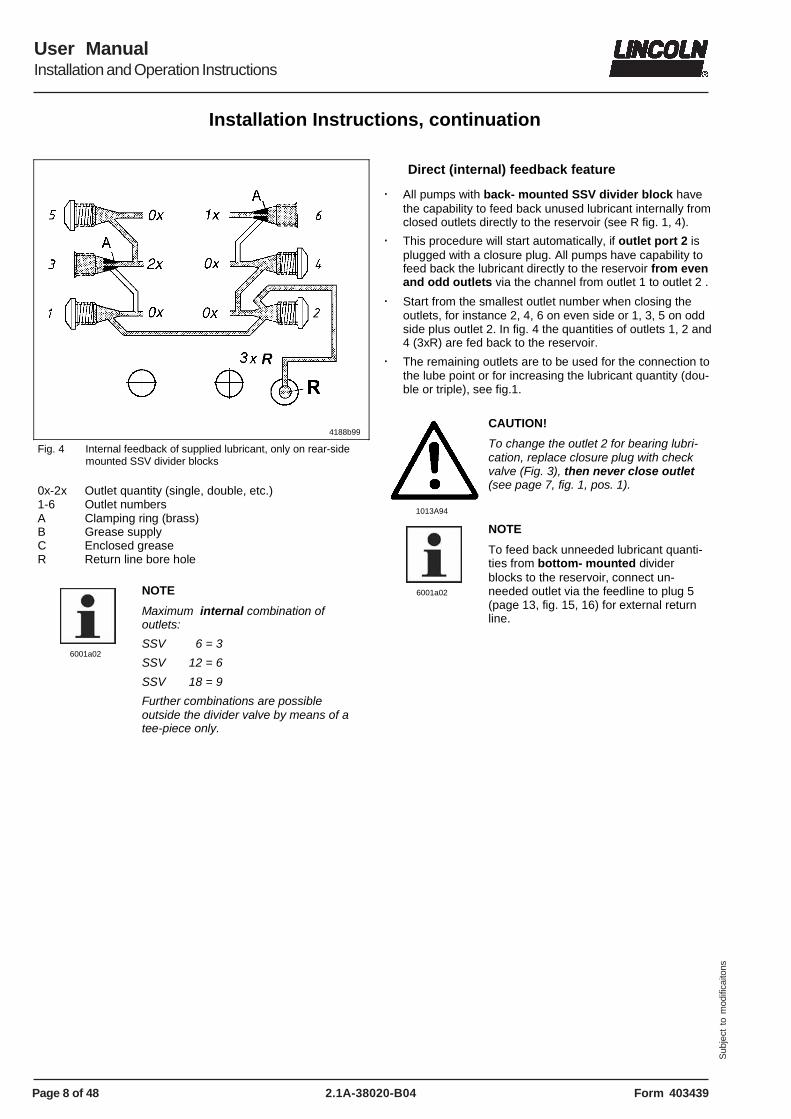
4188b99
Fig. 4 Internal feedback of supplied lubricant, only on rear-side mounted SSV divider blocks
0x-2x Outlet quantity (single, double, etc.) 1-6 Outlet numbers A Clamping ring (brass) B Grease supply C Enclosed grease R Return line bore hole
6001a02
NOTE
Maximum internal combination of outlets:
SSV 6 = 3
SSV 12 = 6
SSV 18 = 9
Further combinations are possible outside the divider valve by means of a tee-piece only.
Direct (internal) feedback feature
� All pumps with back- mounted SSV divider block have the capability to feed back unused lubricant internally from closed outlets directly to the reservoir (see R fig. 1, 4).
� This procedure will start automatically, if outlet port 2 is plugged with a closure plug. All pumps have capability to feed back the lubricant directly to the reservoir from even and odd outlets via the channel from outlet 1 to outlet 2 .
� Start from the smallest outlet number when closing the outlets, for instance 2, 4, 6 on even side or 1, 3, 5 on odd side plus outlet 2. In fig. 4 the quantities of outlets 1, 2 and 4 (3xR) are fed back to the reservoir.
� The remaining outlets are to be used for the connection to the lube point or for increasing the lubricant quantity (dou-ble or triple), see fig.1.
1013A94
CAUTION!
To change the outlet 2 for bearing lubri-cation, replace closure plug with check valve (Fig. 3), then never close outlet (see page 7, fig. 1, pos. 1).
6001a02
NOTE
To feed back unneeded lubricant quanti-ties from bottom- mounted divider blocks to the reservoir, connect un-needed outlet via the feedline to plug 5 (page 13, fig. 15, 16) for external return line.
Page 9 of 48
User ManualInstallation and Operation Instructions
2.1A-38020-B04Form 403439
Sub
ject
to
mod
ifica
itons
Installation Instructions, continuation
Lubrication Points
Installing Quicklinc fittings into lube points
Remove hydraulic lube fittings from lube points and install appropriate Quicklinc fittings into the bore holes of the lube points.
Installing Zerk-Locks onto Grease Fittings
4200a99
4201a99
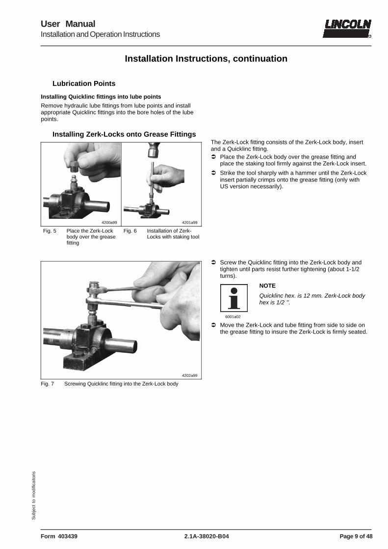
Fig. 5 Place the Zerk-Lock body over the grease fitting
Fig. 6 Installation of Zerk-Locks with staking tool
4202a99
Fig. 7 Screwing Quicklinc fitting into the Zerk-Lock body
The Zerk-Lock fitting consists of the Zerk-Lock body, insert and a Quicklinc fitting. � Place the Zerk-Lock body over the grease fitting and
place the staking tool firmly against the Zerk-Lock insert.
� Strike the tool sharply with a hammer until the Zerk-Lock insert partially crimps onto the grease fitting (only with US version necessarily).
� Screw the Quicklinc fitting into the Zerk-Lock body and tighten until parts resist further tightening (about 1-1/2 turns).
6001a02
NOTE
Quicklinc hex. is 12 mm. Zerk-Lock body hex is 1/2 ’’.
� Move the Zerk-Lock and tube fitting from side to side on the grease fitting to insure the Zerk-Lock is firmly seated.
Page 10 of 48
User ManualInstallation and Operation Instructions
2.1A-38020-B04 Form 403439
Sub
ject
to
mod
ifica
itons
Installation Instructions, continuation
Connection of Feed Lines
4203a99
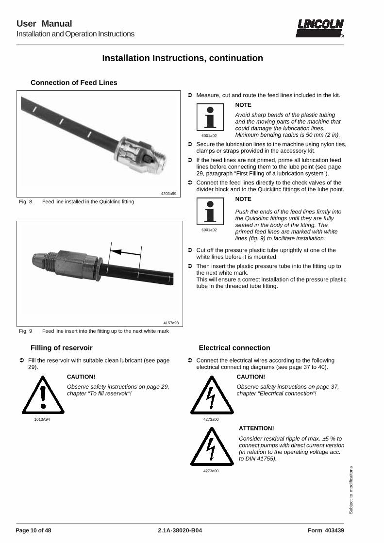
Fig. 8 Feed line installed in the Quicklinc fitting
4157a98
Fig. 9 Feed line insert into the fitting up to the next white mark
� Measure, cut and route the feed lines included in the kit.
6001a02
NOTE
Avoid sharp bends of the plastic tubing and the moving parts of the machine that could damage the lubrication lines. Minimum bending radius is 50 mm (2 in).
� Secure the lubrication lines to the machine using nylon ties, clamps or straps provided in the accessory kit.
� If the feed lines are not primed, prime all lubrication feed lines before connecting them to the lube point (see page 29, paragraph “First Filling of a lubrication system”).
� Connect the feed lines directly to the check valves of the divider block and to the Quicklinc fittings of the lube point.
6001a02
NOTE
Push the ends of the feed lines firmly into the Quicklinc fittings until they are fully seated in the body of the fitting. The primed feed lines are marked with white lines (fig. 9) to facilitate installation.
� Cut off the pressure plastic tube uprightly at one of the white lines before it is mounted.
� Then insert the plastic pressure tube into the fitting up to the next white mark. This will ensure a correct installation of the pressure plastic tube in the threaded tube fitting.
Filling of reservoir
� Fill the reservoir with suitable clean lubricant (see page 29).
1013A94
CAUTION!
Observe safety instructions on page 29, chapter “To fill reservoir“!
Electrical connection
� Connect the electrical wires according to the following electrical connecting diagrams (see page 37 to 40).
4273a00
CAUTION!
Observe safety instructions on page 37, chapter “Electrical connection”!
4273a00
ATTENTION!
Consider residual ripple of max. ±5 % to connect pumps with direct current version (in relation to the operating voltage acc. to DIN 41755).
Page 11 of 48
User ManualInstallation and Operation Instructions
2.1A-38020-B04Form 403439
Sub
ject
to
mod
ifica
itons
Installation Instructions, contiuation
Option for metric fittings (to order separately)
SSV Connecting tube fitting, screw-type and push-in type
4239a99
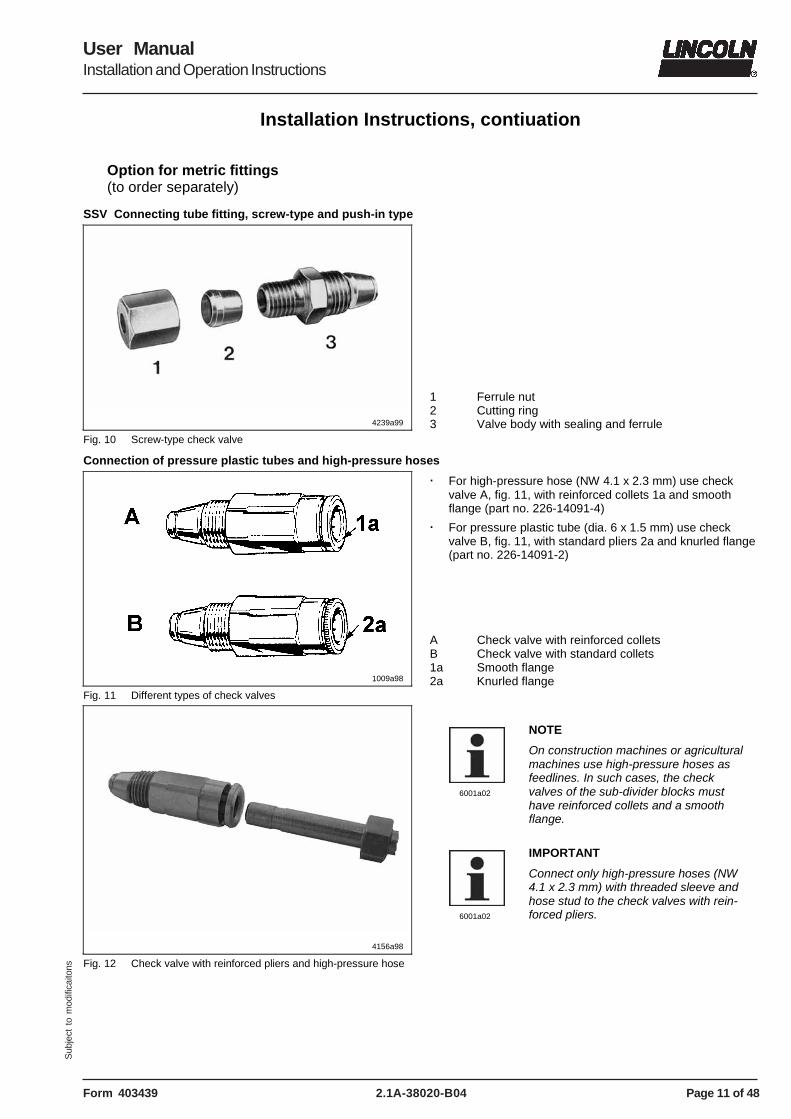
Fig. 10 Screw-type check valve
1 Ferrule nut 2 Cutting ring 3 Valve body with sealing and ferrule
Connection of pressure plastic tubes and high-pressure hoses
1009a98
Fig. 11 Different types of check valves
� For high-pressure hose (NW 4.1 x 2.3 mm) use check valve A, fig. 11, with reinforced collets 1a and smooth flange (part no. 226-14091-4)
� For pressure plastic tube (dia. 6 x 1.5 mm) use check valve B, fig. 11, with standard pliers 2a and knurled flange (part no. 226-14091-2)
A Check valve with reinforced collets B Check valve with standard collets 1a Smooth flange 2a Knurled flange
4156a98
Fig. 12 Check valve with reinforced pliers and high-pressure hose
6001a02
NOTE
On construction machines or agricultural machines use high-pressure hoses as feedlines. In such cases, the check valves of the sub-divider blocks must have reinforced collets and a smooth flange.
6001a02
IMPORTANT
Connect only high-pressure hoses (NW 4.1 x 2.3 mm) with threaded sleeve and hose stud to the check valves with rein-forced pliers.
Page 12 of 48
User ManualInstallation and Operation Instructions
2.1A-38020-B04 Form 403439
Sub
ject
to
mod
ifica
itons
Installation Instructions, continuation
Option for metric fittings, continuation (to order separately)
Mounting of the threaded sleeves and hose studs onto the high-pressure hose
1028a96
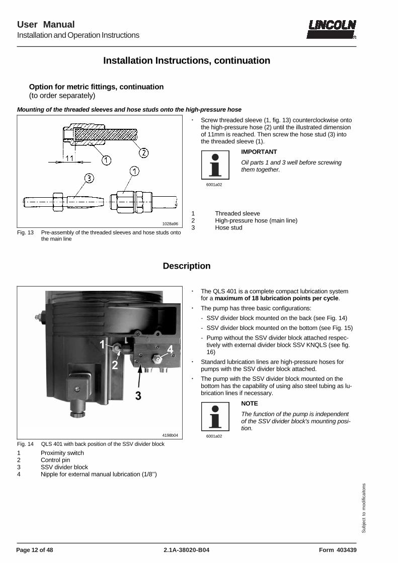
Fig. 13 Pre-assembly of the threaded sleeves and hose studs onto the main line
� Screw threaded sleeve (1, fig. 13) counterclockwise onto the high-pressure hose (2) until the illustrated dimension of 11mm is reached. Then screw the hose stud (3) into the threaded sleeve (1).
6001a02
IMPORTANT
Oil parts 1 and 3 well before screwing them together.
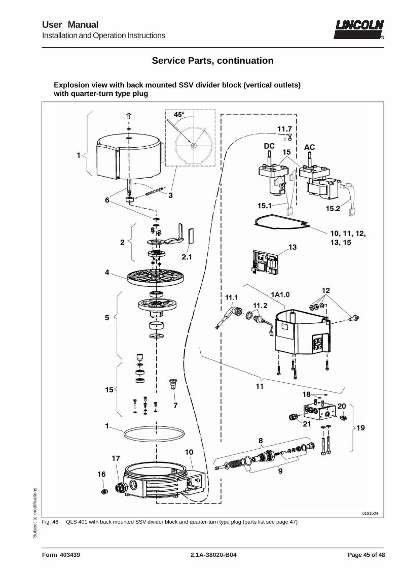
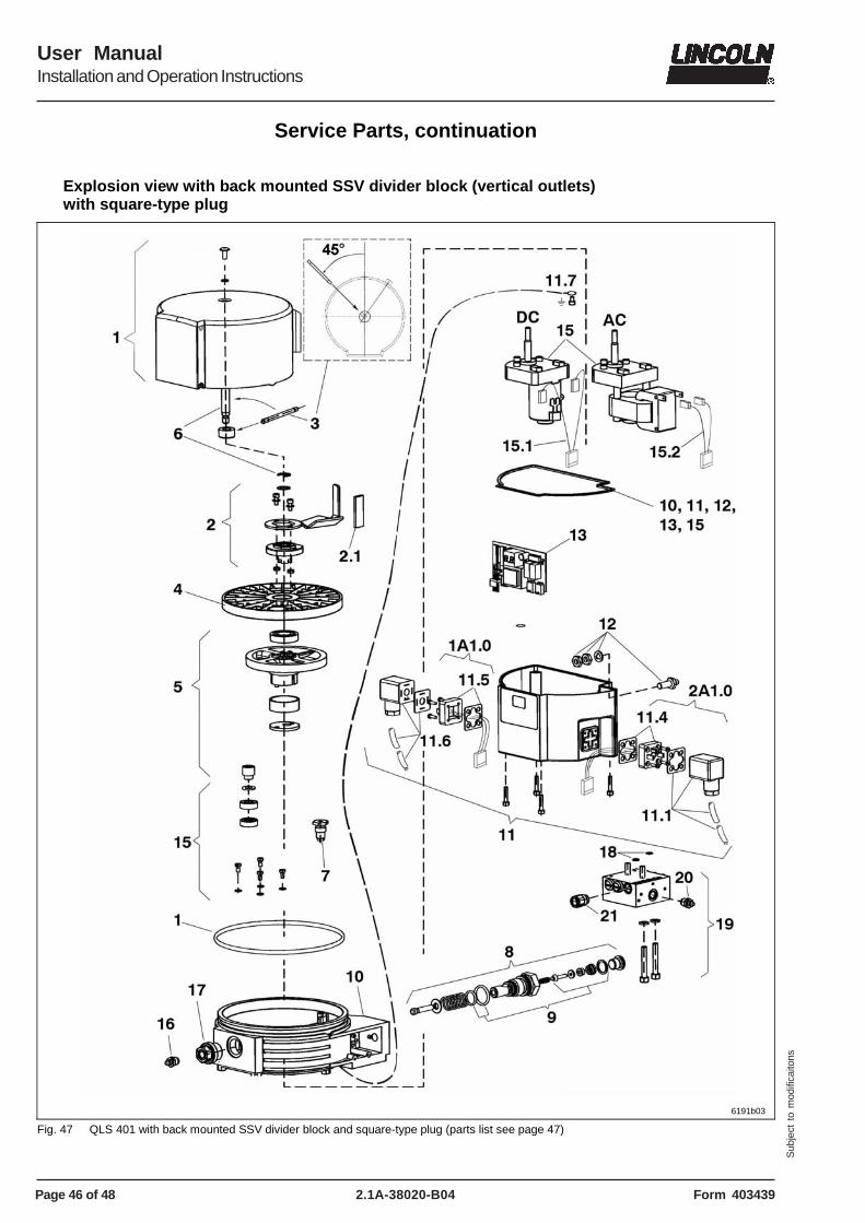
Fig. 14 QLS 401 with back position of the SSV divider block
1 Proximity switch 2 Control pin 3 SSV divider block 4 Nipple for external manual lubrication (1/8’’)
� The QLS 401 is a complete compact lubrication system for a maximum of 18 lubrication points per cycle.
� The pump has three basic configurations:
- SSV divider block mounted on the back (see Fig. 14)
- SSV divider block mounted on the bottom (see Fig. 15)
- Pump without the SSV divider block attached respec-tively with external divider block SSV KNQLS (see fig. 16)
� Standard lubrication lines are high-pressure hoses for pumps with the SSV divider block attached.
� The pump with the SSV divider block mounted on the bottom has the capability of using also steel tubing as lu-brication lines if necessary.
6001a02
NOTE
The function of the pump is independent of the SSV divider block's mounting posi-tion.
Page 13 of 48
User ManualInstallation and Operation Instructions
2.1A-38020-B04Form 403439
Sub
ject
to
mod
ifica
itons
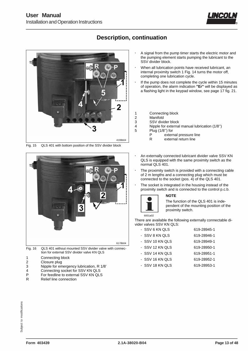
Description, continuation
4199b04
Fig. 15 QLS 401 with bottom position of the SSV divider block
� A signal from the pump timer starts the electric motor and
the pumping element starts pumping the lubricant to the SSV divider block.
� When all lubrication points have received lubricant, an internal proximity switch 1 Fig. 14 turns the motor off, completing one lubrication cycle.
� If the pump does not complete the cycle within 15 minutes of operation, the alarm indication ”Er” will be displayed as a flashing light in the keypad window, see page 17 fig. 21.
1 Connecting block 2 Manifold 3 SSV divider block 4 Nipple for external manual lubrication (1/8’’) 5 Plug (1/8’’) for
P external pressure line R external return line
6178b04
Fig. 16 QLS 401 without mounted SSV divider valve with connec-tion for external SSV divider valve KN QLS
1 Connecting block 2 Closure plug 3 Nipple for emergency lubrication, R 1/8’ 4 Connecting socket for SSV KN QLS P For feedline to external SSV KN QLS R Relief line connection
� An externally connected lubricant divider valve SSV KN QLS is equipped with the same proximity switch as the normal QLS 401.
� The proximity switch is provided with a connecting cable of 2 m lengths and a connecting plug which must be connected to the socket (pos. 4) of the QLS 401.
� The socket is integrated in the housing instead of the proximity switch and is connected to the control p.c.b.
6001a02
NOTE
The function of the QLS 401 is inde-pendent of the mounting position of the proximity switch.
There are available the following externally connectable di-vider valves SSV KN QLS:
- SSV 6 KN QLS 619-28945-1
- SSV 8 KN QLS 619-28946-1
- SSV 10 KN QLS 619-28949-1
- SSV 12 KN QLS 619-28950-1
- SSV 14 KN QLS 619-28951-1
- SSV 16 KN QLS 619-28952-1
- SSV 18 KN QLS 619-28953-1
Page 14 of 48
User ManualInstallation and Operation Instructions
2.1A-38020-B04 Form 403439
Sub
ject
to
mod
ifica
itons
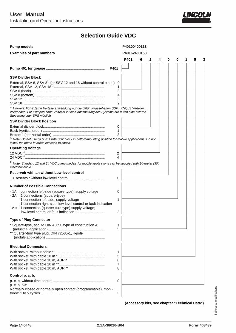
Selection Guide VDC
Pump models P40100400113
Examples of part numbers P40162400153
P401 6 2 4 0 0 1 5 3
Pump 401 for grease ........................................................... P401
2) Hinweis: Für externe Verteileranwendung nur die dafür vorgesehenen SSV...KNQLS Verteiler verwenden. Für Pumpen ohne Verteiler ist eine Abschaltung des Systems nur durch eine externe Steuerung oder SPS möglich.
1) Note: Standard 12 and 24 VDC pump models for mobile applications can be supplied with 10-meter (30’) electrical cable.
Reservoir with an without Low-level control
1 L reservoir without low level control ...................................
0
Number of Possible Connections
- 1A = connection left-side (square-type), supply voltage - 2A = 2 connections (square-type) 1 connection left-side, supply voltage 1 connection right-side, low-level control or fault indication 1A = 1 connection (quarter-turn type) supply voltage; low-level control or fault indication .............................
0
1
2
Type of Plug Connector
* Square-type, acc. to DIN 43650 type of construction A (industrial application) ........................................................ ** Quarter-turn type plug, DIN 72585-1, 4-pole (mobile application) ...........................................................
1 5
Electrical Connectors
With socket, without cable * .................................................. With socket, with cable 10 m * .............................................. With socket, with cable 10 m, ADR * With socket, with cable 10 m **.............................................. With socket, with cable 10 m, ADR **
1 5 6 7 8
Control p. c. b.
p. c. b. without time control .................................................... p. c. b. S3: Normally closed or normally open contact (programmable), moni-tored: 1 to 5 cycles.................................................................
0
3
(Accessory kits, see chapter ”Technical Data“)
Page 15 of 48
User ManualInstallation and Operation Instructions
2.1A-38020-B04Form 403439
Sub
ject
to
mod
ifica
itons
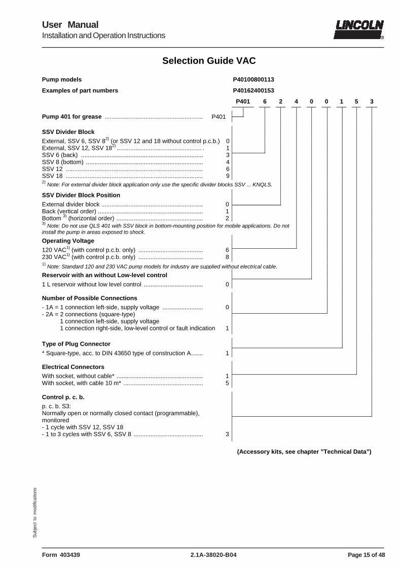
Selection Guide VAC
Pump models P40100800113
Examples of part numbers P40162400153
P401 6 2 4 0 0 1 5 3
Pump 401 for grease .......................................................... P401
3) Note: Do not use QLS 401 with SSV block in bottom-mounting position for mobile applications. Do not install the pump in areas exposed to shock.
Operating Voltage
120 VAC1) (with control p.c.b. only) ...................................... 230 VAC1) (with control p.c.b. only) ......................................
6 8
1) Note: Standard 120 and 230 VAC pump models for industry are supplied without electrical cable. Reservoir with an without Low-level control
1 L reservoir without low level control ...................................
0
Number of Possible Connections
- 1A = 1 connection left-side, supply voltage ........................ - 2A = 2 connections (square-type) 1 connection left-side, supply voltage 1 connection right-side, low-level control or fault indication
0
1
Type of Plug Connector
* Square-type, acc. to DIN 43650 type of construction A.......
1
Electrical Connectors
With socket, without cable* ................................................... With socket, with cable 10 m* ...............................................
1 5
Control p. c. b.
p. c. b. S3: Normally open or normally closed contact (programmable), monitored - 1 cycle with SSV 12, SSV 18 - 1 to 3 cycles with SSV 6, SSV 8 .........................................
3
(Accessory kits, see chapter ”Technical Data”)
Page 16 of 48
User ManualInstallation and Operation Instructions
2.1A-38020-B04 Form 403439
Sub
ject
to
mod
ifica
itons
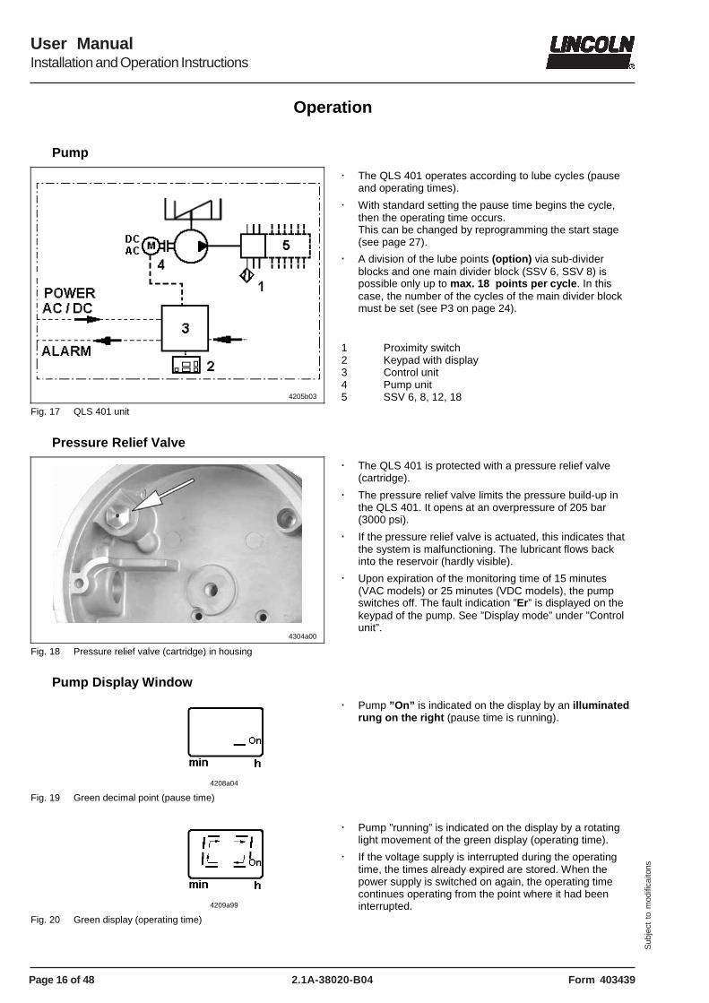
Operation
Pump
4205b03
Fig. 17 QLS 401 unit
� The QLS 401 operates according to lube cycles (pause and operating times).
� With standard setting the pause time begins the cycle, then the operating time occurs. This can be changed by reprogramming the start stage (see page 27).
� A division of the lube points (option) via sub-divider blocks and one main divider block (SSV 6, SSV 8) is possible only up to max. 18 points per cycle. In this case, the number of the cycles of the main divider block must be set (see P3 on page 24).
1 Proximity switch 2 Keypad with display 3 Control unit 4 Pump unit 5 SSV 6, 8, 12, 18
Pressure Relief Valve
4304a00
Fig. 18 Pressure relief valve (cartridge) in housing
� The QLS 401 is protected with a pressure relief valve (cartridge).
� The pressure relief valve limits the pressure build-up in the QLS 401. It opens at an overpressure of 205 bar (3000 psi).
� If the pressure relief valve is actuated, this indicates that the system is malfunctioning. The lubricant flows back into the reservoir (hardly visible).
� Upon expiration of the monitoring time of 15 minutes (VAC models) or 25 minutes (VDC models), the pump switches off. The fault indication ”Er” is displayed on the keypad of the pump. See ”Display mode” under ”Control unit”.
Pump Display Window
4208a04
Fig. 19 Green decimal point (pause time)
� Pump ”On” is indicated on the display by an illuminated rung on the right (pause time is running).
4209a99
Fig. 20 Green display (operating time)
� Pump ”running” is indicated on the display by a rotating light movement of the green display (operating time).
� If the voltage supply is interrupted during the operating time, the times already expired are stored. When the power supply is switched on again, the operating time continues operating from the point where it had been interrupted.
Page 17 of 48
User ManualInstallation and Operation Instructions
2.1A-38020-B04Form 403439
Sub
ject
to
mod
ifica
itons
Operation, continuation
Monitoring time/ malfunction
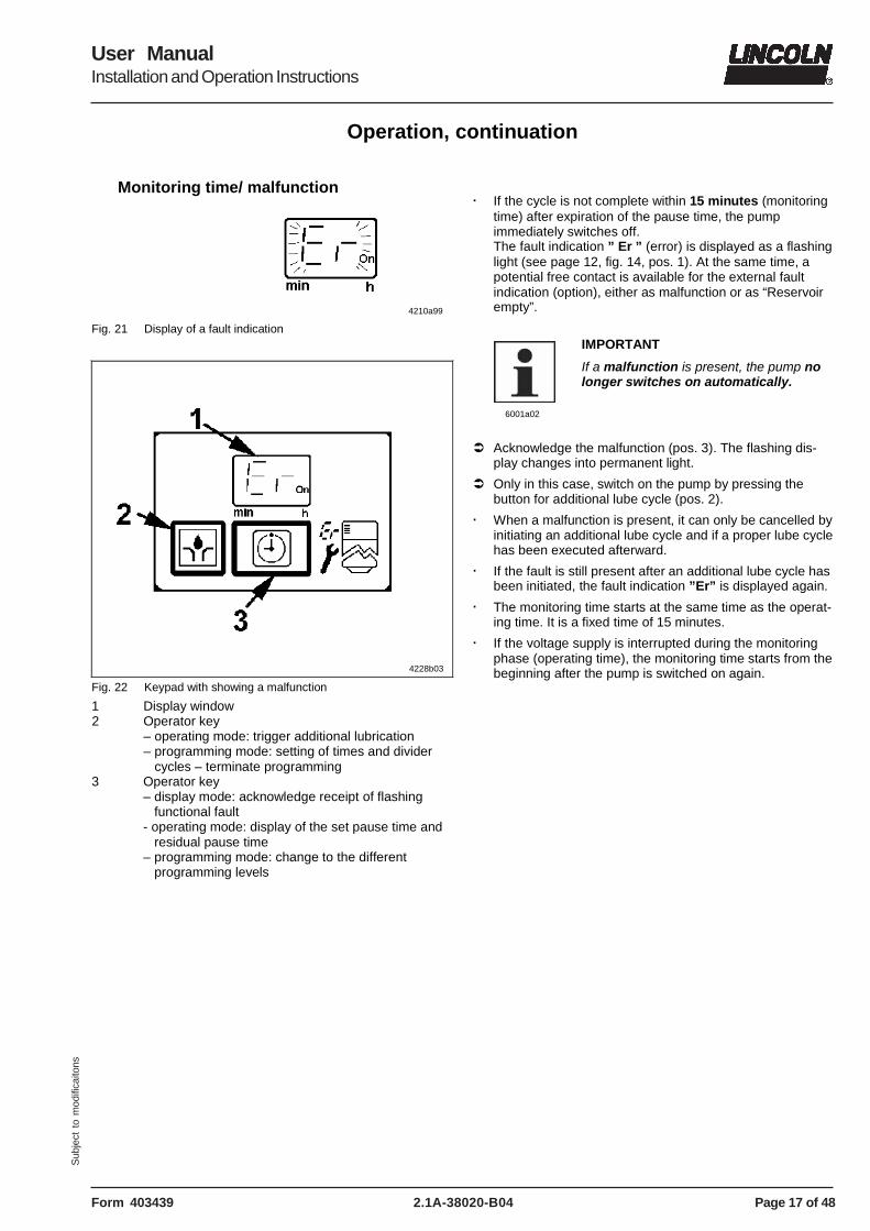
4210a99
Fig. 21 Display of a fault indication
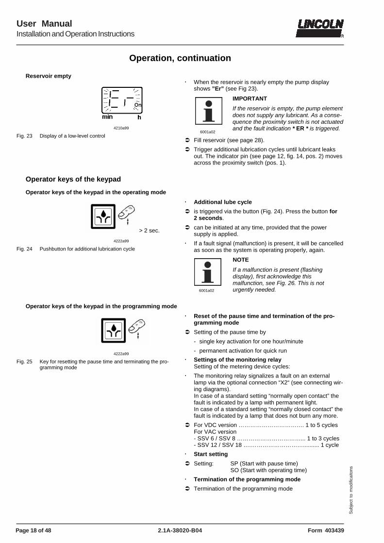
4228b03
Fig. 22 Keypad with showing a malfunction
1 Display window 2 Operator key
– operating mode: trigger additional lubrication – programming mode: setting of times and divider cycles – terminate programming
3 Operator key – display mode: acknowledge receipt of flashing functional fault - operating mode: display of the set pause time and residual pause time – programming mode: change to the different programming levels
� If the cycle is not complete within 15 minutes (monitoring
time) after expiration of the pause time, the pump immediately switches off. The fault indication ” Er ” (error) is displayed as a flashing light (see page 12, fig. 14, pos. 1). At the same time, a potential free contact is available for the external fault indication (option), either as malfunction or as “Reservoir empty”.
6001a02
IMPORTANT
If a malfunction is present, the pump no longer switches on automatically.
� Acknowledge the malfunction (pos. 3). The flashing dis-
play changes into permanent light.
� Only in this case, switch on the pump by pressing the button for additional lube cycle (pos. 2).
� When a malfunction is present, it can only be cancelled by initiating an additional lube cycle and if a proper lube cycle has been executed afterward.
� If the fault is still present after an additional lube cycle has been initiated, the fault indication ”Er” is displayed again.
� The monitoring time starts at the same time as the operat-ing time. It is a fixed time of 15 minutes.
� If the voltage supply is interrupted during the monitoring phase (operating time), the monitoring time starts from the beginning after the pump is switched on again.
Page 18 of 48
User ManualInstallation and Operation Instructions
2.1A-38020-B04 Form 403439
Sub
ject
to
mod
ifica
itons
Operation, continuation
Reservoir empty
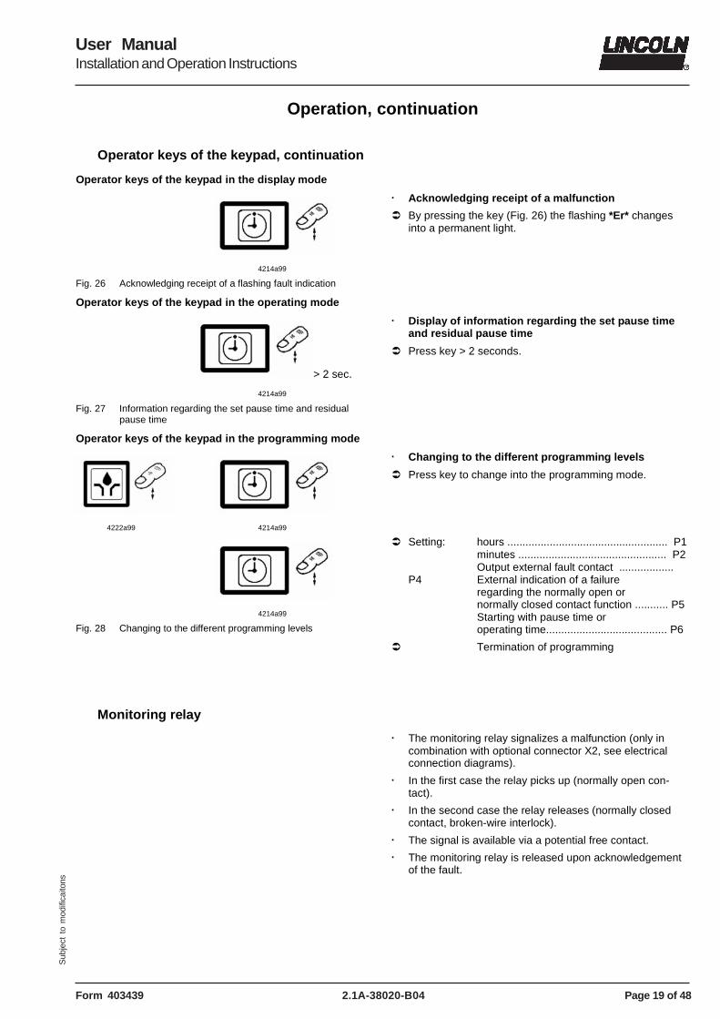
4210a99
Fig. 23 Display of a low-level control
� When the reservoir is nearly empty the pump display
shows ”Er” (see Fig 23).
6001a02
IMPORTANT
If the reservoir is empty, the pump element does not supply any lubricant. As a conse-quence the proximity switch is not actuated and the fault indication * ER * is triggered.
� Fill reservoir (see page 28).
� Trigger additional lubrication cycles until lubricant leaks out. The indicator pin (see page 12, fig. 14, pos. 2) moves across the proximity switch (pos. 1).
Operator keys of the keypad
Operator keys of the keypad in the operating mode
> 2 sec.
4222a99
Fig. 24 Pushbutton for additional lubrication cycle
� Additional lube cycle
� is triggered via the button (Fig. 24). Press the button for 2 seconds.
� can be initiated at any time, provided that the power supply is applied.
� If a fault signal (malfunction) is present, it will be cancelled as soon as the system is operating properly, again.
6001a02
NOTE
If a malfunction is present (flashing display), first acknowledge this malfunction, see Fig. 26. This is not urgently needed.
Operator keys of the keypad in the programming mode
4222a99
Fig. 25 Key for resetting the pause time and terminating the pro-gramming mode
� Reset of the pause time and termination of the pro-gramming mode
� Setting of the pause time by
- single key activation for one hour/minute
- permanent activation for quick run
� Settings of the monitoring relay Setting of the metering device cycles:
� The monitoring relay signalizes a fault on an external lamp via the optional connection “X2“ (see connecting wir-ing diagrams). In case of a standard setting “normally open contact” the fault is indicated by a lamp with permanent light. In case of a standard setting “normally closed contact” the fault is indicated by a lamp that does not burn any more.
� For VDC version ……………………………. 1 to 5 cycles For VAC version - SSV 6 / SSV 8 ……………………………... 1 to 3 cycles - SSV 12 / SSV 18 ….……………………….......... 1 cycle
� Start setting
� Setting: SP (Start with pause time) SO (Start with operating time)
� Termination of the programming mode
� Termination of the programming mode
Page 19 of 48
User ManualInstallation and Operation Instructions
2.1A-38020-B04Form 403439
Sub
ject
to
mod
ifica
itons
Operation, continuation
Operator keys of the keypad, continuation
Operator keys of the keypad in the display mode
4214a99
Fig. 26 Acknowledging receipt of a flashing fault indication
� Acknowledging receipt of a malfunction
� By pressing the key (Fig. 26) the flashing *Er* changes into a permanent light.
Operator keys of the keypad in the operating mode
> 2 sec.
4214a99
Fig. 27 Information regarding the set pause time and residual pause time
� Display of information regarding the set pause time and residual pause time
� Press key > 2 seconds.
Operator keys of the keypad in the programming mode
4222a99
4214a99
4214a99
Fig. 28 Changing to the different programming levels
� Changing to the different programming levels
� Press key to change into the programming mode. � Setting: hours ..................................................... P1
minutes ................................................. P2 Output external fault contact .................. P4 External indication of a failure regarding the normally open or normally closed contact function ........... P5 Starting with pause time or operating time........................................ P6
� Termination of programming
Monitoring relay
� The monitoring relay signalizes a malfunction (only in combination with optional connector X2, see electrical connection diagrams).
� In the first case the relay picks up (normally open con-tact).
� In the second case the relay releases (normally closed contact, broken-wire interlock).
� The signal is available via a potential free contact.
� The monitoring relay is released upon acknowledgement of the fault.
Page 20 of 48
User ManualInstallation and Operation Instructions
2.1A-38020-B04 Form 403439
Sub
ject
to
mod
ifica
itons
Setting and Operation
General
6001a02
NOTE QLS 401
Depending on the version, the QLS 401 is factory-fit with the corresponding printed circuit board: - for 12/24 VDC … 236-14212-7 - for 120 VAC …… 236-10298-6 - for 230 VAC …… 236-10298-1 However, the QLS 401 does not yet pos-sess a function for a low-level indication (LL). The indication is effected as a fault indication (Er).
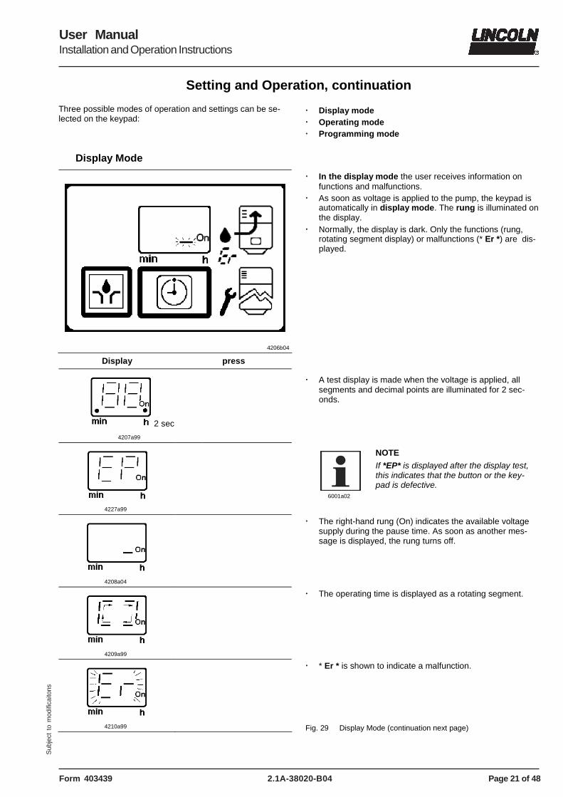
� In the display mode the user receives information on functions and malfunctions.
� As soon as voltage is applied to the pump, the keypad is automatically in display mode. The rung is illuminated on the display.
� Normally, the display is dark. Only the functions (rung, rotating segment display) or malfunctions (* Er *) are dis-played.
Display press
2 sec
4207a99
4227a99
� A test display is made when the voltage is applied, all
segments and decimal points are illuminated for 2 sec-onds.
6001a02
NOTE
If *EP* is displayed after the display test, this indicates that the button or the key-pad is defective.
4208a04
� The right-hand rung (On) indicates the available voltage supply during the pause time. As soon as another mes-sage is displayed, the rung turns off.
4209a99
� The operating time is displayed as a rotating segment.
4210a99
� * Er * is shown to indicate a malfunction. Fig. 29 Display Mode (continuation next page)
Page 22 of 48
User ManualInstallation and Operation Instructions
2.1A-38020-B04 Form 403439
Sub
ject
to
mod
ifica
itons
Setting and Operation, continuation
Display Mode, continuation
< 2 sec.
4214a99
4212a99
Fig. 29 Display Mode
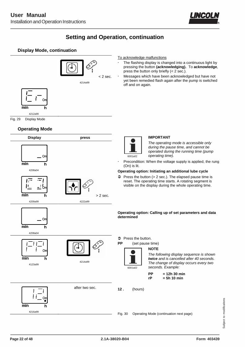
To acknowledge malfunctions � The flashing display is changed into a continuous light by
pressing the button (acknowledging). To acknowledge, press the button only briefly (< 2 sec.).
� Messages which have been acknowledged but have not yet been remedied flash again after the pump is switched off and on again.
Operating Mode
Display press
4208a04
4209a99
> 2 sec.
4222a99
6001a02
IMPORTANT
The operating mode is accessible only during the pause time, and cannot be operated during the running time (pump operating time).
� Precondition: When the voltage supply is applied, the rung (On) is lit.
Operating option: Initiating an additional lube cycle
� Press the button (> 2 sec.). The elapsed pause time is reset. The operating time starts. A rotating segment is visible on the display during the whole operating time.
4208a04
Operating option: Calling up of set parameters and data determined
4123a99
4214a99
� Press the button. PP (set pause time)
6001a02
NOTE
The following display sequence is shown twice and is cancelled after 40 seconds. The change of display occurs every two seconds. Example:
PP = 12h 30 min rP = 5h 10 min
4216a99
after two sec.
12 . (hours)
Fig. 30 Operating Mode (continuation next page)
Page 23 of 48
User ManualInstallation and Operation Instructions
2.1A-38020-B04Form 403439
Sub
ject
to
mod
ifica
itons
Setting and Operation, continuation
Operating Mode, continuation
4220a99
after two sec.
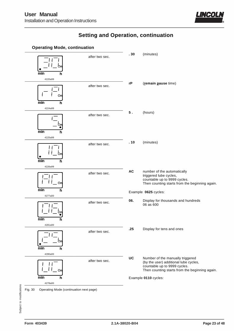
. 30 (minutes)
4224a99
after two sec.
rP (remain pause time)
4225a99
after two sec.
5 . (hours)
4226a99
after two sec.
. 10 (minutes)
4277a00
after two sec.
AC number of the automatically triggered lube cycles, countable up to 9999 cycles. Then counting starts from the beginning again. Example 0625 cycles:
4281a00
after two sec.
06. Display for thousands and hundreds 06 as 600
4280a00
after two sec.
.25 Display for tens and ones
4278a00
after two sec.
UC Number of the manually triggered (by the user) additional lube cycles, countable up to 9999 cycles. Then counting starts from the beginning again. Example 0110 cycles:
Fig. 30 Operating Mode (continuation next page)
Page 24 of 48
User ManualInstallation and Operation Instructions
2.1A-38020-B04 Form 403439
Sub
ject
to
mod
ifica
itons
Setting and Operation, continuation
4297a00
after two sec.
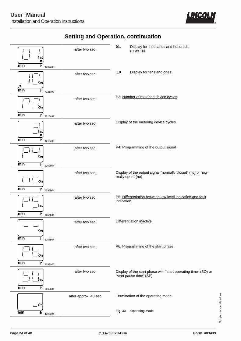
01. Display for thousands and hundreds 01 as 100
4226a99
after two sec.
.10 Display for tens and ones
4218a99
after two sec.
4219a99
after two sec.
6252b04
after two sec.
6253b04
after two sec.
6255b04
after two sec.
6256b04
after two sec.
4299a00
after two sec.
6260b04
after two sec.
4208a04
after approx. 40 sec.
P3: Number of metering device cycles Display of the metering device cycles P4: Programming of the output signal Display of the output signal “normally closed“ (nc) or “nor-mally open“ (no) P5: Differentiation between low-level indication and fault indication Differentiation inactive P6: Programming of the start phase Display of the start phase with “start operating time“ (SO) or “start pause time“ (SP) Termination of the operating mode Fig. 30 Operating Mode
Page 25 of 48
User ManualInstallation and Operation Instructions
2.1A-38020-B04Form 403439
Sub
ject
to
mod
ifica
itons
Setting and Operation, continuation
Programming Mode
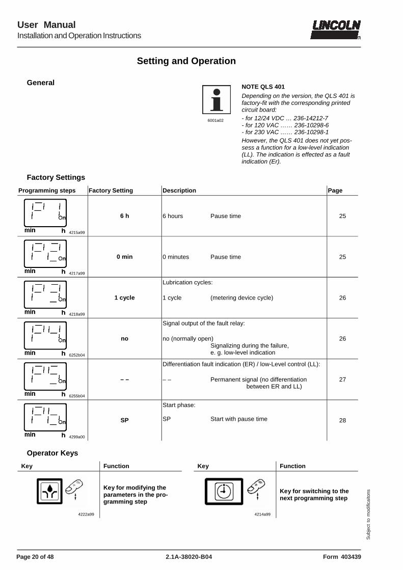
Display Activity
4215a99
4222a99
4214a99
> 4 sec.
4281a00
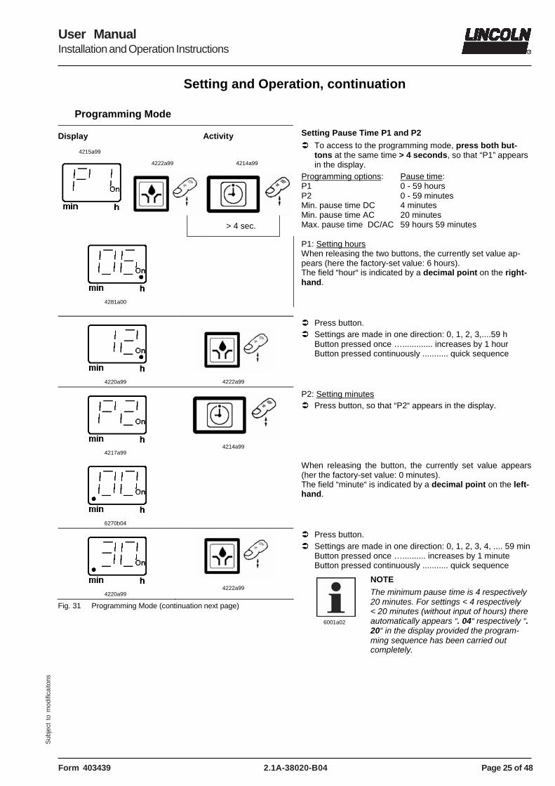
Setting Pause Time P1 and P2
� To access to the programming mode, press both but-tons at the same time > 4 seconds, so that “P1” appears in the display.
Programming options: Pause time: P1 0 - 59 hours P2 0 - 59 minutes Min. pause time DC 4 minutes Min. pause time AC 20 minutes Max. pause time DC/AC 59 hours 59 minutes P1: Setting hours When releasing the two buttons, the currently set value ap-pears (here the factory-set value: 6 hours). The field “hour“ is indicated by a decimal point on the right-hand.
4220a99
4222a99
4217a99
4214a99
6270b04
4220a99
4222a99
Fig. 31 Programming Mode (continuation next page)
� Press button. � Settings are made in one direction: 0, 1, 2, 3,....59 h
Button pressed once …............. increases by 1 hour Button pressed continuously ........... quick sequence
P2: Setting minutes � Press button, so that “P2“ appears in the display. When releasing the button, the currently set value appears (her the factory-set value: 0 minutes). The field “minute“ is indicated by a decimal point on the left-hand. � Press button. � Settings are made in one direction: 0, 1, 2, 3, 4, .... 59 min
Button pressed once ….......... increases by 1 minute Button pressed continuously ........... quick sequence
6001a02
NOTE
The minimum pause time is 4 respectively 20 minutes. For settings < 4 respectively < 20 minutes (without input of hours) there automatically appears “. 04“ respectively “. 20“ in the display provided the program-ming sequence has been carried out completely.
Page 26 of 48
User ManualInstallation and Operation Instructions
2.1A-38020-B04 Form 403439
Sub
ject
to
mod
ifica
itons
Setting and Operation, continuation
Programming Mode, continuation
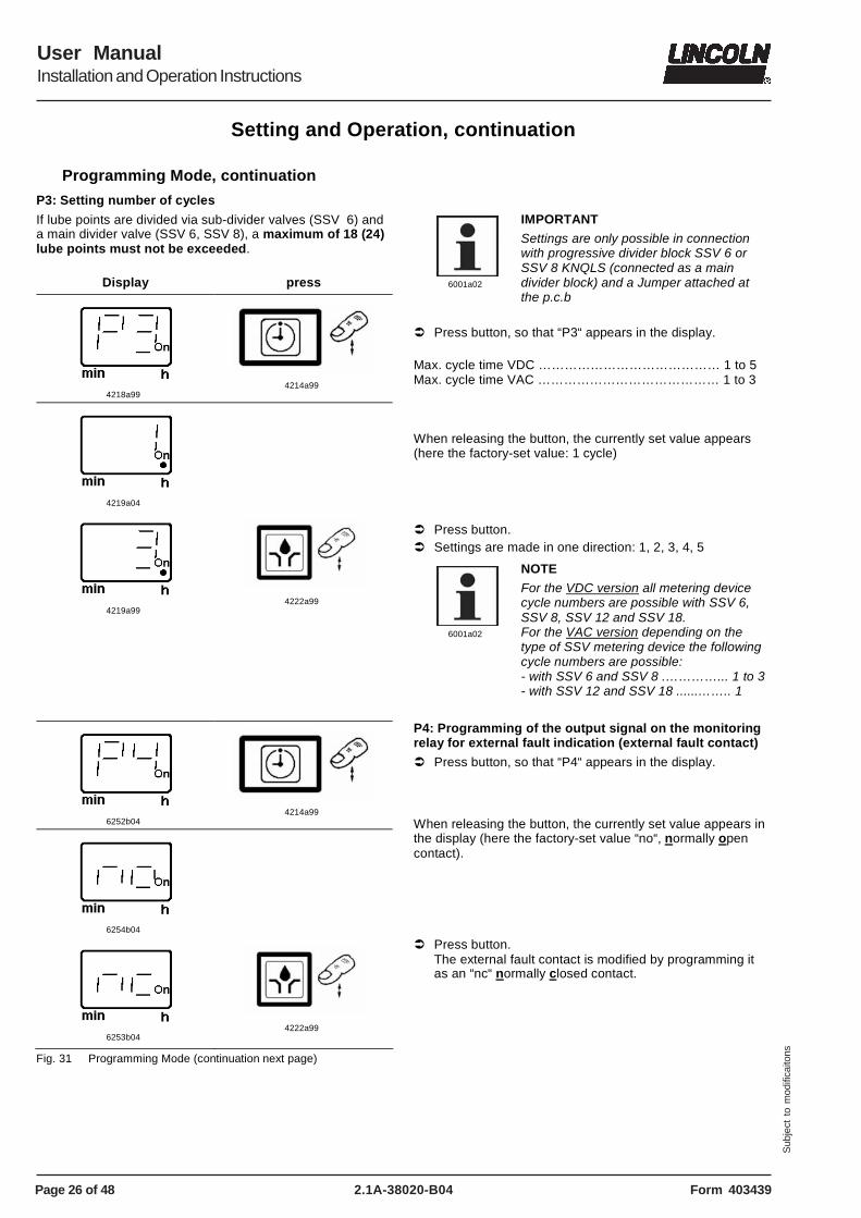
P3: Setting number of cycles
If lube points are divided via sub-divider valves (SSV 6) and a main divider valve (SSV 6, SSV 8), a maximum of 18 (24) lube points must not be exceeded.
Display press
4218a99
4214a99
4219a04
4219a99
4222a99
6001a02
IMPORTANT
Settings are only possible in connection with progressive divider block SSV 6 or SSV 8 KNQLS (connected as a main divider block) and a Jumper attached at the p.c.b
� Press button, so that “P3“ appears in the display. Max. cycle time VDC …………………………………… 1 to 5 Max. cycle time VAC …………………………………… 1 to 3 When releasing the button, the currently set value appears (here the factory-set value: 1 cycle) � Press button. � Settings are made in one direction: 1, 2, 3, 4, 5
6001a02
NOTE
For the VDC version all metering device cycle numbers are possible with SSV 6, SSV 8, SSV 12 and SSV 18. For the VAC version depending on the type of SSV metering device the following cycle numbers are possible: - with SSV 6 and SSV 8 .…………... 1 to 3 - with SSV 12 and SSV 18 ......…….. 1
6252b04
4214a99
6254b04
6253b04
4222a99
Fig. 31 Programming Mode (continuation next page)
P4: Programming of the output signal on the monitoring relay for external fault indication (external fault contact)
� Press button, so that “P4“ appears in the display. When releasing the button, the currently set value appears in the display (here the factory-set value “no“, normally open contact). � Press button.
The external fault contact is modified by programming it as an “nc“ normally closed contact.
Page 27 of 48
User ManualInstallation and Operation Instructions
2.1A-38020-B04Form 403439
Sub
ject
to
mod
ifica
itons
Setting and Operation, continuation
Programming Mode, continuation
6255b04
4214a99
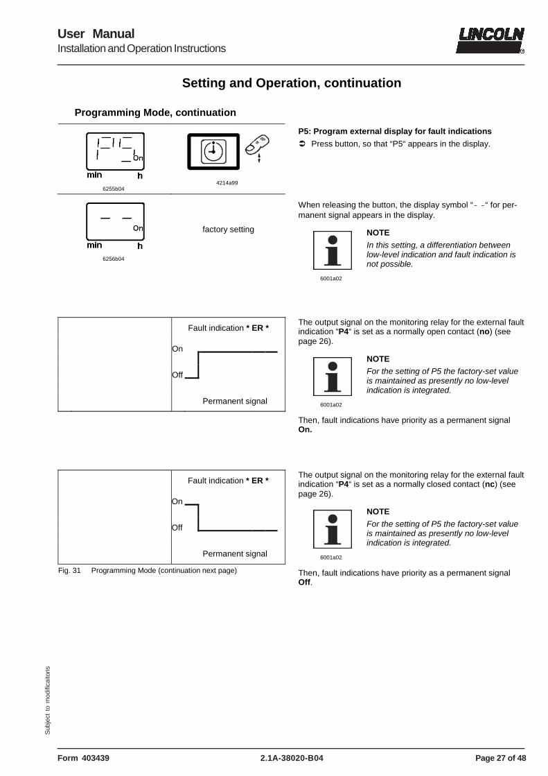
P5: Program external display for fault indications
� Press button, so that “P5“ appears in the display.
6256b04
factory setting
When releasing the button, the display symbol “- -“ for per-manent signal appears in the display.
6001a02
NOTE
In this setting, a differentiation between low-level indication and fault indication is not possible.
Fault indication * ER *
On
Off
Permanent signal
The output signal on the monitoring relay for the external fault indication “P4“ is set as a normally open contact (no) (see page 26).
6001a02
NOTE For the setting of P5 the factory-set value is maintained as presently no low-level indication is integrated.
Then, fault indications have priority as a permanent signal On.
Fault indication * ER *
On
Off
Permanent signal
Fig. 31 Programming Mode (continuation next page)
The output signal on the monitoring relay for the external fault indication “P4“ is set as a normally closed contact (nc) (see page 26).
6001a02
NOTE
For the setting of P5 the factory-set value is maintained as presently no low-level indication is integrated.
Then, fault indications have priority as a permanent signal Off.
Page 28 of 48
User ManualInstallation and Operation Instructions
2.1A-38020-B04 Form 403439
Sub
ject
to
mod
ifica
itons
Setting and Operation, continuation
Programming Mode, continuation
4299a00
4214a99
6259b04
6260b04
4222a99
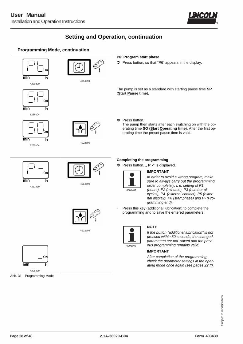
P6: Program start phase
� Press button, so that “P6“ appears in the display.
The pump is set as a standard with starting pause time SP (Start Pause time).
� Press button. The pump then starts after each switching on with the op-erating time SO (Start Operating time). After the first op-erating time the preset pause time is valid.
4221a99
4214a99
4222a99
4208a99
Abb. 31 Programming Mode
Completing the programming � Press button. „ P -“ is displayed.
6001a02
IMPORTANT
In order to avoid a wrong program, make sure to always carry out the programming order completely, i. e. setting of P1 (hours), P2 (minutes), P3 (number of cycles), P4 (external contact), P5 (exter-nal display), P6 (start phase) and P- (Pro-gramming end).
� Press this key (additional lubrication) to complete the programming and to save the entered parameters.
6001a02
NOTE
If the button “additional lubrication” is not pressed within 30 seconds, the changed parameters are not saved and the previ-ous programming remains valid.
IMPORTANT
After completion of the programming, check the parameter settings in the oper-ating mode once again (see pages 22 ff).
Page 29 of 48
User ManualInstallation and Operation Instructions
2.1A-38020-B04Form 403439
Sub
ject
to
mod
ifica
itons
Maintenance, Repair and Tests
Maintenance
� Maintenance is essentially limited to refilling the reservoir with clean lubricant as necessary. However, check regu-larly whether the lubricant is being dispensed to all the lu-brication points.
� Also check the feed lines for damage and replace them, if necessary.
4273a00
CAUTION!
Turn off the voltage supply for pumps 120 VAC and 230 VAC before servicing the pump.
6001a02
NOTE
Whenever work is performed on the centralized lubrication system, special attention should be paid to cleanliness. Dirt will cause failure of the system.
IMPORTANT
To clean the system use petroleum spirit or petroleum. Do not use Tri, Per or similar solvents or polar or organic sol-vents such as alcohol, methanol, acetone, etc.
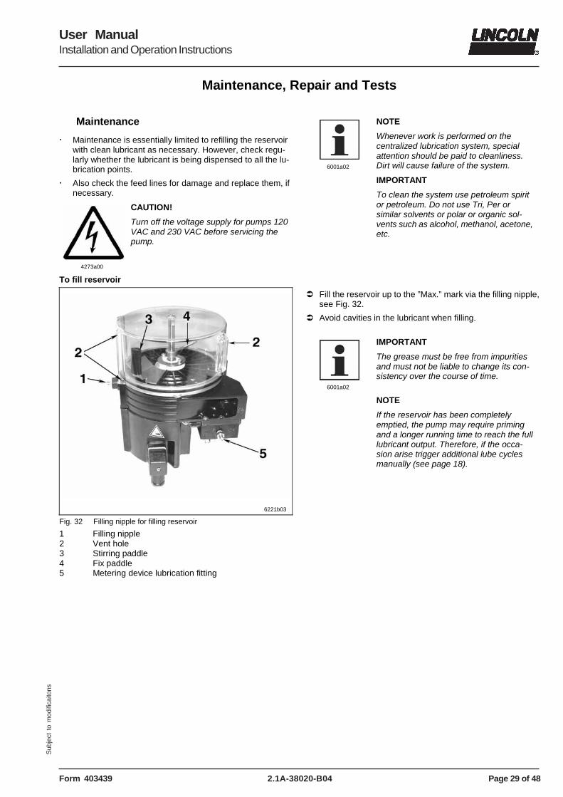
� Fill the reservoir up to the ”Max.” mark via the filling nipple, see Fig. 32.
� Avoid cavities in the lubricant when filling.
6001a02
IMPORTANT
The grease must be free from impurities and must not be liable to change its con-sistency over the course of time.
NOTE
If the reservoir has been completely emptied, the pump may require priming and a longer running time to reach the full lubricant output. Therefore, if the occa-sion arise trigger additional lube cycles manually (see page 18).
Page 30 of 48
User ManualInstallation and Operation Instructions
2.1A-38020-B04 Form 403439
Sub
ject
to
mod
ifica
itons
Maintenance, Repair and Tests, continuation
Maintenance, continuation
First filling of a lubrication system
1013A94
CAUTION!
Risk of bursting if the reservoir is over-filled! When filling the reservoir by means of pumps with a large delivery volume do not exceed the max. filling mark.
1013A94
ATTENTION!
When filling the reservoir, make sure that the air can escape through the venting bores (see fig. 32, pos. 2).
� If necessary, fill the lubrication lines via the lubrication fitting of the metering device (pos. 5) by means of an ex-ternal pump.
� Let the QLS 401 run and fill the empty reservoir through the filler fitting (pos. 1) until lubricant leaks from the meter-ing device outlets.
6001a02
IMPORTANT
Remove the lubrication fitting (pos. 5) for a short time to check the lubricant supply.
� Follow the instructions given on page 28, chapter "To Fill reservoir".
Repair
4273a00
CAUTION!
Switch off the voltage supply for pumps 120 VAC and 230 VAC before servicing the pump.
1013A94
CAUTION!
By operating the drive motor without the reservoir installed, there is a risk of in-jury by the eccentric gear. Never use the Lubrication System QLS 401 without the installed reservoir!
� For repair work on the QLS 401 use only original Lincoln spare parts.
� Using non-Lincoln parts voids the pump warranty.
Functional Test
> 2 sec.
4222a99
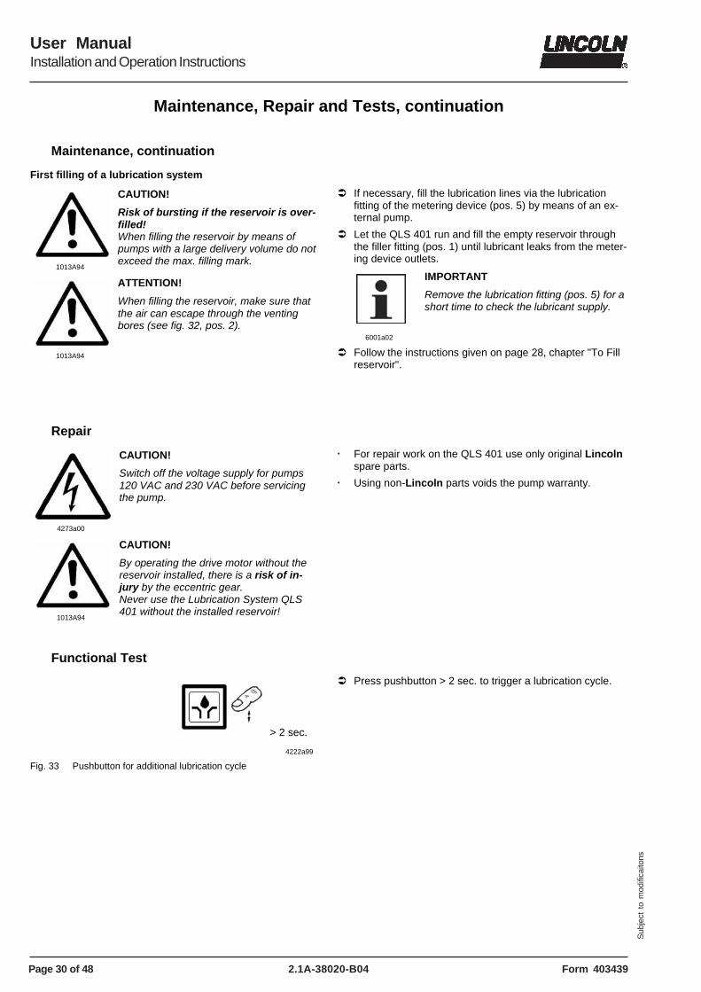
Fig. 33 Pushbutton for additional lubrication cycle
� Press pushbutton > 2 sec. to trigger a lubrication cycle.
Page 31 of 48
User ManualInstallation and Operation Instructions
2.1A-38020-B04Form 403439
Sub
ject
to
mod
ifica
itons
Troubleshooting
Pump of the QLS 401 system
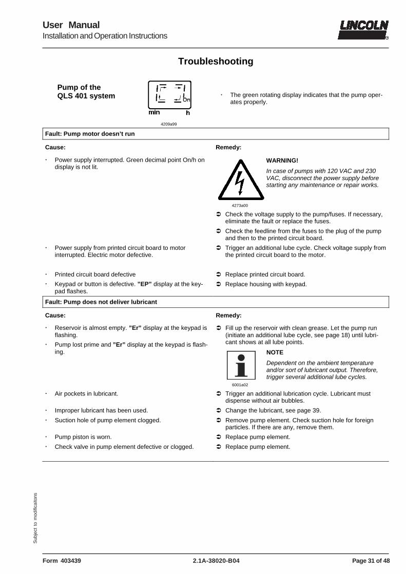
4209a99
� The green rotating display indicates that the pump oper-ates properly.
Fault: Pump motor doesn’t run
Cause: Remedy:
� Power supply interrupted. Green decimal point On/h on display is not lit.
4273a00
WARNING!
In case of pumps with 120 VAC and 230 VAC, disconnect the power supply before starting any maintenance or repair works.
� Check the voltage supply to the pump/fuses. If necessary, eliminate the fault or replace the fuses.
� Check the feedline from the fuses to the plug of the pump and then to the printed circuit board.
� Power supply from printed circuit board to motor interrupted. Electric motor defective.
� Trigger an additional lube cycle. Check voltage supply from the printed circuit board to the motor.
� Keypad or button is defective. ”EP” display at the key-pad flashes.
� Replace housing with keypad.
Fault: Pump does not deliver lubricant
Cause: Remedy:
� Reservoir is almost empty. ”Er” display at the keypad is flashing.
� Pump lost prime and ”Er” display at the keypad is flash-ing.
� Fill up the reservoir with clean grease. Let the pump run (initiate an additional lube cycle, see page 18) until lubri-cant shows at all lube points.
6001a02
NOTE
Dependent on the ambient temperature and/or sort of lubricant output. Therefore, trigger several additional lube cycles.
� Air pockets in lubricant. � Trigger an additional lubrication cycle. Lubricant must dispense without air bubbles.
� Improper lubricant has been used. � Change the lubricant, see page 39.
� Suction hole of pump element clogged. � Remove pump element. Check suction hole for foreign particles. If there are any, remove them.
� Pump piston is worn. � Replace pump element.
� Check valve in pump element defective or clogged. � Replace pump element.
Page 32 of 48
User ManualInstallation and Operation Instructions
2.1A-38020-B04 Form 403439
Sub
ject
to
mod
ifica
itons
Troubleshooting, continuation
Fault: Pump either does not switch off at all or only after the monitoring time of 15 min.
Cause: Remedy:
� Proximity switch is not dampened, i.e. the control pin does not move within the switching range of the proximity switch, or the distance between the control pin and the proximity switch surface is more than 0.5 mm (0.02 in.).
� Trigger additional lubrication (see page 18). Check whether the control pin moves centrically over the switch-ing surface of the initiator. In case the adjustments do not correspond to the indications, the fixing position of the me-tering device has to be corrected.
� Check the distance.
- Between the control pin and the switching surface of the initiator (max. 0.5 mm; 0.02 in.)
In case the adjustments do not correspond to the indica-tions, the fixing position of the proximity switch has to be corrected.
- Distances between the switching surface of the initiator and the upper edge of the fixing nut: When the divider block is mounted at the back: 16+ / –0,2 mm (0.62+/-0.08 in.) When the divider block is mounted at the bottom: 12,7 +/-0,1 mm (0.5 +/-0.004 in.).
� Tightening torque of the nut: 1,5 NM (1.10 ft-lb.).
Fault: Pump runs continuously
Cause: Remedy:
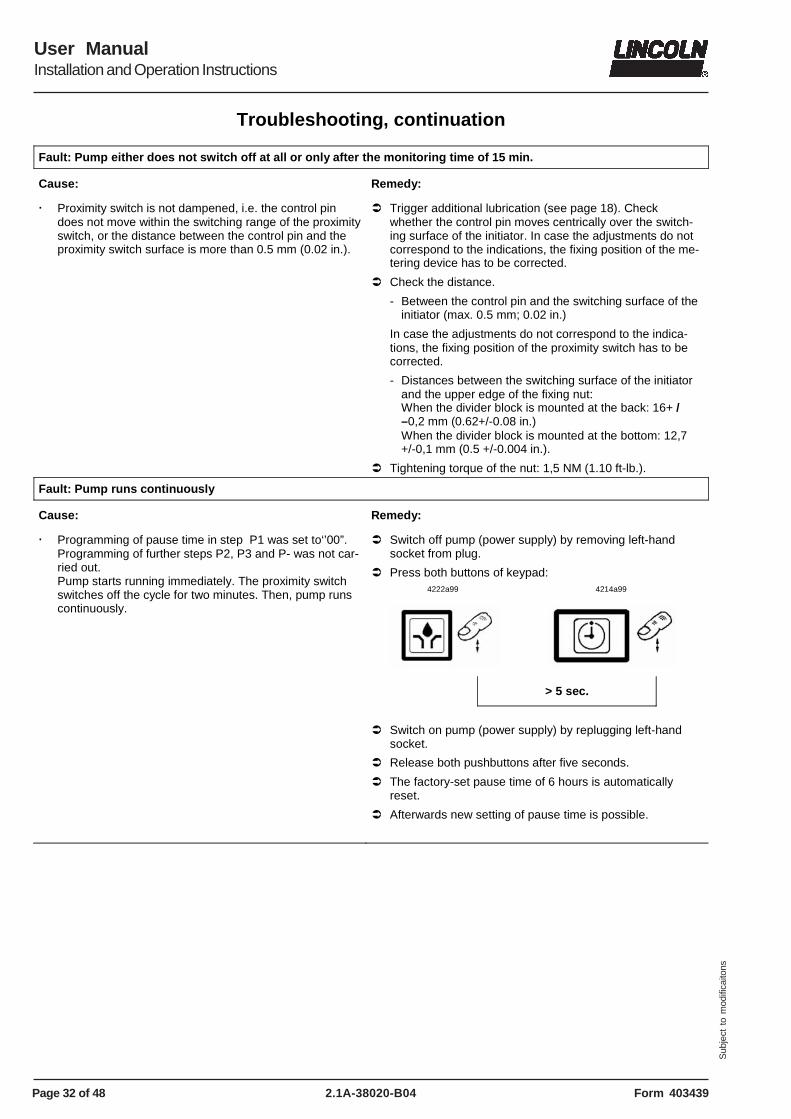
� Programming of pause time in step P1 was set to‘’00”. Programming of further steps P2, P3 and P- was not car-ried out. Pump starts running immediately. The proximity switch switches off the cycle for two minutes. Then, pump runs continuously.
� Switch off pump (power supply) by removing left-hand socket from plug.
� Press both buttons of keypad: 4222a99
4214a99
> 5 sec.
� Switch on pump (power supply) by replugging left-hand
socket.
� Release both pushbuttons after five seconds.
� The factory-set pause time of 6 hours is automatically reset.
� Afterwards new setting of pause time is possible.
Page 33 of 48
User ManualInstallation and Operation Instructions
2.1A-38020-B04Form 403439
Sub
ject
to
mod
ifica
itons
Troubleshooting, continuation
SSV divider block
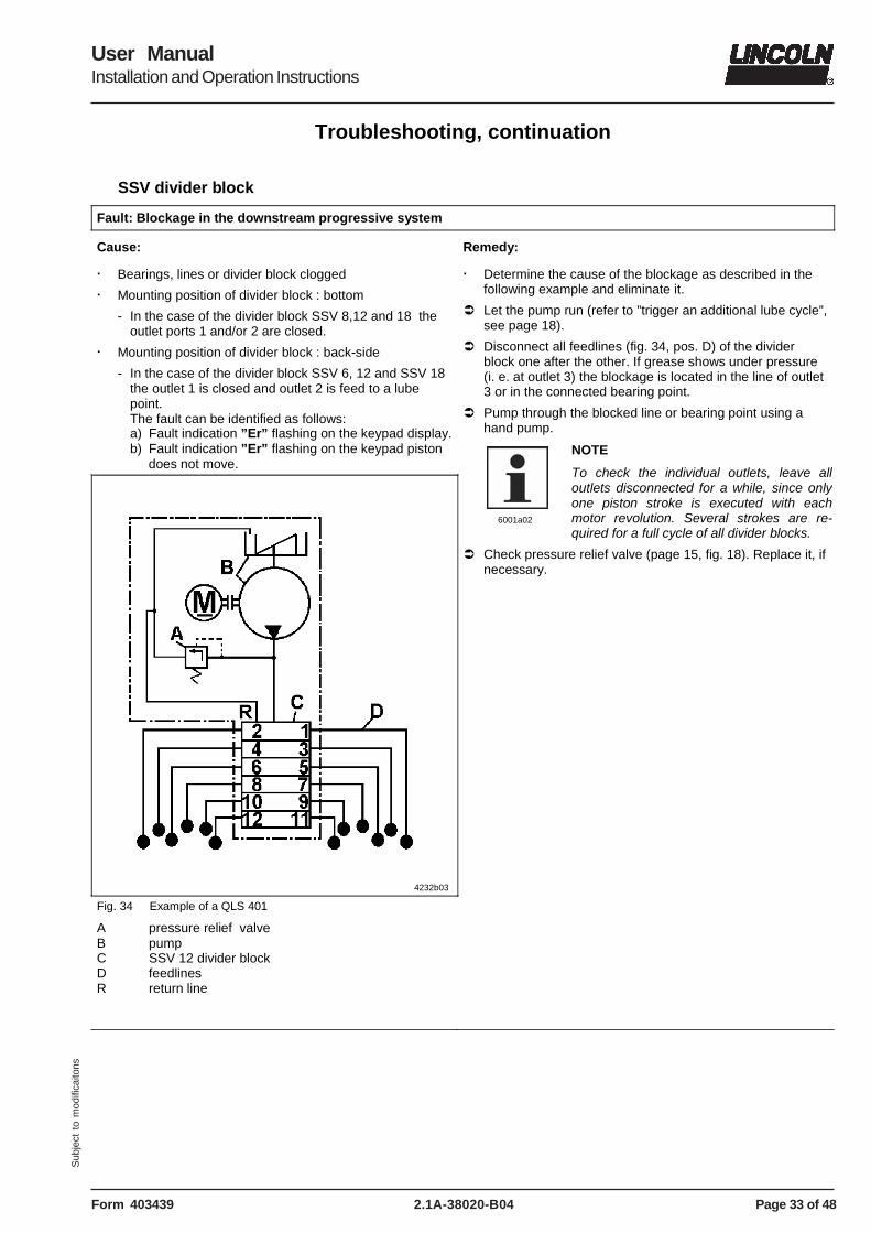
Fault: Blockage in the downstream progressive system
Cause: Remedy:
� Bearings, lines or divider block clogged
� Mounting position of divider block : bottom
- In the case of the divider block SSV 8,12 and 18 the outlet ports 1 and/or 2 are closed.
� Mounting position of divider block : back-side
- In the case of the divider block SSV 6, 12 and SSV 18 the outlet 1 is closed and outlet 2 is feed to a lube point. The fault can be identified as follows: a) Fault indication ”Er” flashing on the keypad display. b) Fault indication ”Er” flashing on the keypad piston does not move.
4232b03
Fig. 34 Example of a QLS 401
A pressure relief valve B pump C SSV 12 divider block D feedlines R return line
� Determine the cause of the blockage as described in the following example and eliminate it.
� Let the pump run (refer to ”trigger an additional lube cycle”, see page 18).
� Disconnect all feedlines (fig. 34, pos. D) of the divider block one after the other. If grease shows under pressure (i. e. at outlet 3) the blockage is located in the line of outlet 3 or in the connected bearing point.
� Pump through the blocked line or bearing point using a hand pump.
6001a02
NOTE
To check the individual outlets, leave all outlets disconnected for a while, since only one piston stroke is executed with each motor revolution. Several strokes are re-quired for a full cycle of all divider blocks.
User ManualInstallation and Operation Instructions
2.1A-38020-B04 Form 403439
Sub
ject
to
mod
ifica
itons
Troubleshooting, continuation
Fault: Blockage in the downstream progressive system, continuation
Cause: Remedy:
� Divider valve is blocked � Replace the divider block or clean it as follows:
- Remove all threaded tube fittings.
- Unscrew the piston closure plugs.
- Remove the piston, if possible, with a soft mandrel (smaller than ø 6 mm, 0.24 in).
6001a02
IMPORTANT
The pistons are individually fit in the bores of the divider block. After removing the pistons, mark them in order to reinstall them in the right direction and position. They may not be interchanged.
- Thoroughly clean the divider block body in a grease-desolving detergent and dry it with compressed air.
- Clean through the material passages (ø 1.5 mm, 0.59 in) at the thread ends of the piston bores using a pin.
- Clean the divider block once more and dry it thoroughly.
- Reassemble the divider block.
Fault: Differing lubricant amounts at the lubrication point
Cause: Remedy:
� Lubricant metering not correct.
� Setting of the pause time incorrect.
� Check the lubricant metering acc. to the lubrication chart.
� Check time setting.
Page 35 of 48
User ManualInstallation and Operation Instructions
2.1A-38020-B04Form 403439
Sub
ject
to
mod
ifica
itons
Technical Data
QLS 401, GENERAL
Operating temperature........ -25° C to 70° C (-10° F to 160° F) Maximum operating pressure of pump model without divider block ........... 205 bar (3,000 psig) Number of outlets................................................... 6, 8, 12, 18 Output per outlet and cycle .................................... ca. 0,2 cm² Reservoir capacity ...............................................................1 l Lubricant ..................................................up to NLGI 2 Grease Weight (average) ......................................... 5.7 kg. (12.5 lbs.) Protection................................. IP6K 9K acc. to DIN 40050 T9 Reverse polarity protection: The operating voltage inlets are protected against reverse polarity.
ELECTRICAL DATA AC (ALTERNATE CURRENT)
Operating voltage.............................. 120 VAC/60 Hz +/- 10 % Operating current .............................................................1,0 A Operating voltage........................ 230 VAC; 50/60 Hz +/- 10 % Operating current .............................................................0,5 A
ELECTRICAL DATA DC (DIRECT CURRENT)
Operating voltage...................................... 12 V, - 20%/+ 30 % Operating current .............................................................2,0 A Operating voltage...................................... 24 V, - 20%/+ 30 % Operating current ............................................................1,0 A Residual ripple in relation to the operating voltage ...................... ± 5% acc. to DIN41755
6001a02
NOTE
The pump motor is suitable for intermit-tent operation only.
� In addition to the EMV directive, the DC systems also comply with the following guidelines and standards:
- the vehicle guideline 95/245/EC
- EMV regulation for on-road vehicles acc. EN 40839 parts 1, 3 and 4
TIME SETTING
Factory setting Pause time ..........................................................6 hours/cycle Lubrication cycle time........................20 minutes to 100 hours, .................................................................. increment 1 minute Numbers of cycles, general...........................................1 cycle with SSV 6, SSV 8 .......................1, 2 or 3 cycles are possible Timer memory................................ indefinite over EEPROM
RELAY FOR MALFUNCTION AC
Potential-free outlet for malfunction Switching voltage..............................max. 230 VAC/ 125 VDC Switching current .......................................max. (resistive) 2 A Switching capacity ......................................max. 100 VA/80 W RELAY FOR MALFUNCTION DC
Potential-free outlet for malfunction Switching voltage.......................................max. 48 VAC/ VDC Switching current .......................................max. (resistive) 2 A Switching capacity ......................................max. 100 VA/80 W
6001a02
NOTE
All data depends on operating voltage, ambient temperature and max. operating pressure.
LINES Plastic tube (ø 6x1,5 mm;1/4 in.) Min. bending radius . .............................................50 cm (2 in.) Bursting pressure at 20° C ( 70°F) .............................approx. 210 bar (3050 psi ) Min. temperature ................................................-25° C (-10°F)
TIGHTENING TORQUES Pump Electric motor to housing..................................3 NM (2.5 lb.-ft) Pump element in housing............................25 NM ( 19.0 lb.-ft) Divider block, accessories Closure plug (piston) in divider block...........18 NM (13.5 lb.-ft) Closure plug (outlets) in divider block..........15 NM (11.0 lb.-ft) Outlet fitting in divider block - screw-type ..............................................17 NM (12.5 lb.-ft) - push-in type..............................................12 NM (9.0 lb.-ft) Compression nut onto outlet fitting, screw-type: - plastic tube ...............................................10 NM (7.5 lb.-ft) - steel tube..................................................11 NM (8.0 lb.-ft) Indicator pin in divider block ........................18 NM (13.5 lb.-ft) Mounting of the divider block.........................10 NM (8.0 lb.-ft) ACCESSORY KITS Inch- Size Kits: SSV 6/8 part no. 550-36971-1 SSV 12 part no. 550-36971-2 SSV 18 part no. 550-36971-3 Metric Size Kits: SSV 6/8 part no. 550-36970-1*** SSV 12 part no. 550-36970-2*** SSV 18 part no. 550-36970-3***
*** Lube fittings must be ordered separately
Page 36 of 48
User ManualInstallation and Operation Instructions
2.1A-38020-B04 Form 403439
Sub
ject
to
mod
ifica
itons
Technical Data, continuation
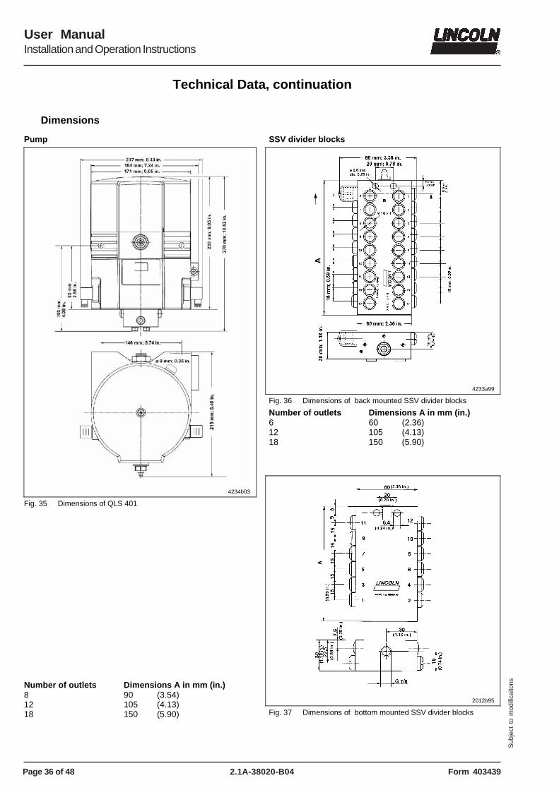
Dimensions
Pump
4234b03
Fig. 35 Dimensions of QLS 401
Number of outlets Dimensions A in mm (in.) 8 90 (3.54) 12 105 (4.13) 18 150 (5.90)
SSV divider blocks
4233a99
Fig. 36 Dimensions of back mounted SSV divider blocks
Number of outlets Dimensions A in mm (in.) 6 60 (2.36) 12 105 (4.13) 18 150 (5.90)
2012b95
Fig. 37 Dimensions of bottom mounted SSV divider blocks
Page 37 of 48
User ManualInstallation and Operation Instructions
2.1A-38020-B04Form 403439
Sub
ject
to
mod
ifica
itons
Technical Data, continuation
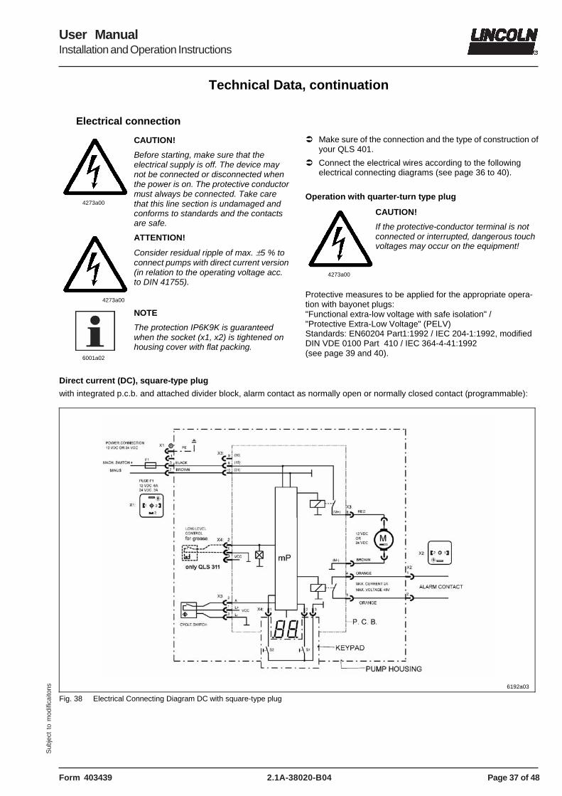
Electrical connection
4273a00
CAUTION!
Before starting, make sure that the electrical supply is off. The device may not be connected or disconnected when the power is on. The protective conductor must always be connected. Take care that this line section is undamaged and conforms to standards and the contacts are safe.
4273a00
ATTENTION!
Consider residual ripple of max. ±5 % to connect pumps with direct current version (in relation to the operating voltage acc. to DIN 41755).
6001a02
NOTE
The protection IP6K9K is guaranteed when the socket (x1, x2) is tightened on housing cover with flat packing.
� Make sure of the connection and the type of construction of your QLS 401.
� Connect the electrical wires according to the following electrical connecting diagrams (see page 36 to 40).
Operation with quarter-turn type plug
4273a00
CAUTION!
If the protective-conductor terminal is not connected or interrupted, dangerous touch voltages may occur on the equipment!
Protective measures to be applied for the appropriate opera-tion with bayonet plugs: "Functional extra-low voltage with safe isolation" / "Protective Extra-Low Voltage" (PELV) Standards: EN60204 Part1:1992 / IEC 204-1:1992, modified DIN VDE 0100 Part 410 / IEC 364-4-41:1992 (see page 39 and 40).
Direct current (DC), square-type plug
with integrated p.c.b. and attached divider block, alarm contact as normally open or normally closed contact (programmable):
6192a03
Fig. 38 Electrical Connecting Diagram DC with square-type plug
Page 38 of 48
User ManualInstallation and Operation Instructions
2.1A-38020-B04 Form 403439
Sub
ject
to
mod
ifica
itons
Technical Data, continuation
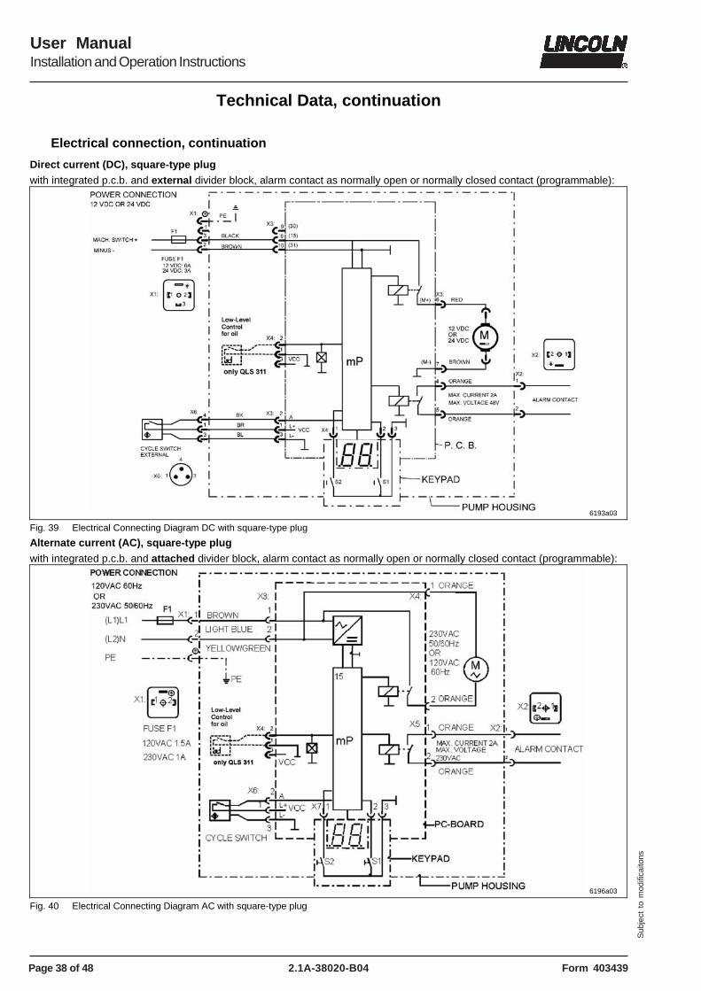
Electrical connection, continuation
Direct current (DC), square-type plug with integrated p.c.b. and external divider block, alarm contact as normally open or normally closed contact (programmable):
6193a03
Fig. 39 Electrical Connecting Diagram DC with square-type plug
Alternate current (AC), square-type plug with integrated p.c.b. and attached divider block, alarm contact as normally open or normally closed contact (programmable):
6196a03
Fig. 40 Electrical Connecting Diagram AC with square-type plug
Page 39 of 48
User ManualInstallation and Operation Instructions
2.1A-38020-B04Form 403439
Sub
ject
to
mod
ifica
itons
Technical Data, continuation
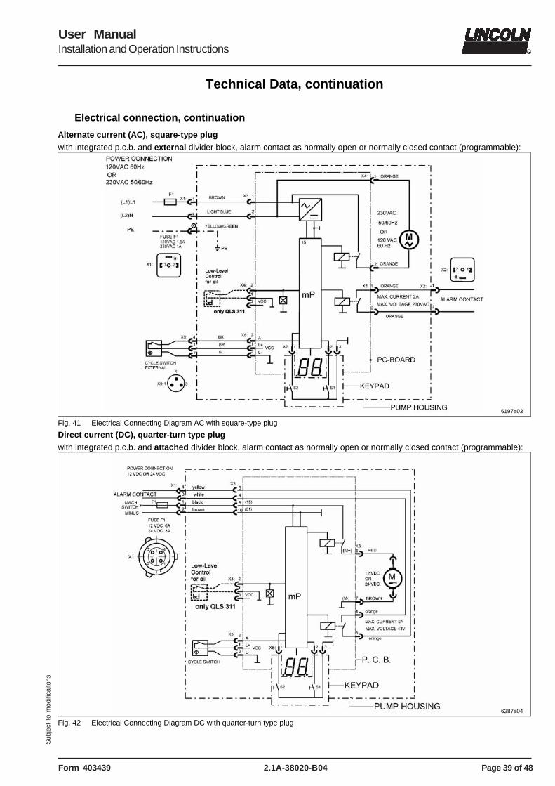
Electrical connection, continuation
Alternate current (AC), square-type plug with integrated p.c.b. and external divider block, alarm contact as normally open or normally closed contact (programmable):
6197a03
Fig. 41 Electrical Connecting Diagram AC with square-type plug
Direct current (DC), quarter-turn type plug with integrated p.c.b. and attached divider block, alarm contact as normally open or normally closed contact (programmable):
6287a04
Fig. 42 Electrical Connecting Diagram DC with quarter-turn type plug
Page 40 of 48
User ManualInstallation and Operation Instructions
2.1A-38020-B04 Form 403439
Sub
ject
to
mod
ifica
itons
Technical Data, continuation
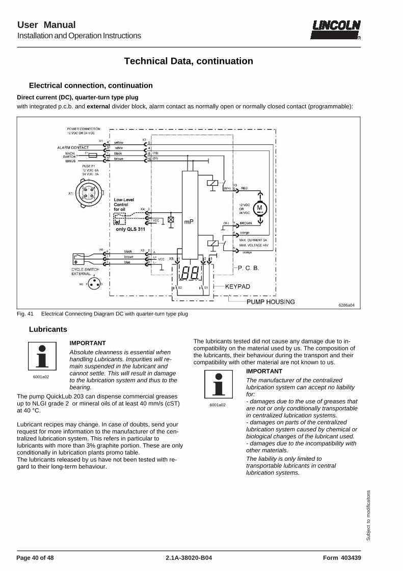
Electrical connection, continuation
Direct current (DC), quarter-turn type plug with integrated p.c.b. and external divider block, alarm contact as normally open or normally closed contact (programmable):
6286a04
Fig. 41 Electrical Connecting Diagram DC with quarter-turn type plug
Lubricants
6001a02
IMPORTANT
Absolute cleanness is essential when handling Lubricants. Impurities will re-main suspended in the lubricant and cannot settle. This will result in damage to the lubrication system and thus to the bearing.
The pump QuickLub 203 can dispense commercial greases up to NLGI grade 2 or mineral oils of at least 40 mm/s (cST) at 40 °C. Lubricant recipes may change. In case of doubts, send your request for more information to the manufacturer of the cen-tralized lubrication system. This refers in particular to lubricants with more than 3% graphite portion. These are only conditionally in lubrication plants promo table. The lubricants released by us have not been tested with re-gard to their long-term behaviour.
The lubricants tested did not cause any damage due to in-compatibility on the material used by us. The composition of the lubricants, their behaviour during the transport and their compatibility with other material are not known to us.
6001a02
IMPORTANT The manufacturer of the centralized lubrication system can accept no liability for: - damages due to the use of greases that are not or only conditionally transportable in centralized lubrication systems. - damages on parts of the centralized lubrication system caused by chemical or biological changes of the lubricant used. - damages due to the incompatibility with other materials. The liability is only limited to transportable lubricants in central lubrication systems.
Page 41 of 48
User ManualInstallation and Operation Instructions
2.1A-38020-B04Form 403439
Sub
ject
to
mod
ifica
itons
Technical Data, continuation
Lubricants, continuation
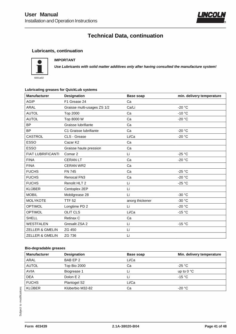
6001a02
IMPORTANT
Use Lubricants with solid matter additives only after having consulted the manufacture system!
Lubricating greases for QuickLub systems
Manufacturer Designation Base soap min. delivery temperature
AGIP F1 Grease 24 Ca
ARAL Graisse multi-usages ZS 1/2 Ca/Li -20 °C
AUTOL Top 2000 Ca -10 °C
AUTOL Top 8000 W Ca -20 °C
BP Graisse lubrifiante Ca
BP C1 Graisse lubrifiante Ca -20 °C
CASTROL CLS - Grease Li/Ca -20 °C
ESSO Cazar K2 Ca
ESSO Graisse haute pression Ca
FIAT LUBRIFICANTI Comar 2 Li -25 °C
FINA CERAN LT Ca -20 °C
FINA CERAN WR2 Ca
FUCHS FN 745 Ca -25 °C
FUCHS Renocal FN3 Ca -20 °C
FUCHS Renolit HLT 2 Li -25 °C
KLÜBER Centoplex 2EP Li
MOBIL Mobilgrease 28 Li -30 °C
MOLYKOTE TTF 52 anorg thickener -30 °C
OPTIMOL Longtime PD 2 Li -20 °C
OPTIMOL OLIT CLS Li/Ca -15 °C
SHELL Retinax C Ca
WESTFALEN Gresalit ZSA 2 Li -15 °C
ZELLER & GMELIN ZG 450 Li
ZELLER & GMELIN ZG 736 Li
Bio-degradable greases
Manufacturer Designation Base soap Min. delivery temperature
ARAL BAB EP 2 Li/Ca
AUTOL Top Bio 2000 Ca -25 °C
AVIA Biogrease 1 Li up to 0 °C
DEA Dolon E 2 Li -15 °C
FUCHS Plantogel S2 Li/Ca
KLÜBER Klüberbio M32-82 Ca -20 °C
Page 42 of 48
User ManualInstallation and Operation Instructions
2.1A-38020-B04 Form 403439
Sub
ject
to
mod
ifica
itons
Service Parts
Explosion view with bottom mounted SSV divider block (horizontal outlets) with square-type plug
6200b03
Fig. 44 QLS 401 with bottom mounted SSV divider block and square-type plug (parts list see page 43)
Page 43 of 48
User ManualInstallation and Operation Instructions
2.1A-38020-B04Form 403439
Sub
ject
to
mod
ifica
itons
Service Parts, continuation
Parts list with bottom mounted SSV divider block (horizontal outlets)
Pos. Designation Kit Single Part
Qty Part no.
1 Reservoir x 1 550-34179-1
2 Stirring paddle with stripper
x 1 550-34178-9
2.1 Stripping rubber x 450-70430-1
3 Pin (fix paddle) x 1 450-70404-1
4 Intermediate bottom x 1 450-24749-1
5 Eccentric gear x 1 550-34178-8
6 Shaft x 1 550-34178-7
7 Pressure relief valve, cartridge
x 1 235-14343-1
8 Pump element, assy. dia. 6 mm
x 1 650-28856-1
9 Sealing parts for pump element
x 1 550-36979-5
10 Housing x 1 550-34179-2
Square-type plug (see page 42, fig. 44)
11 Housing cover for direct current VDC, plug 1A1.0
x 1 550-34178-5
for direct current VDC, plug 2A1.0
x 1 550-34178-4
for alternate current VAC, plug 1A1.0
x 1 550-34178-3
for alternate current VAC, plug1+2 A1.0
x 1 550-34178-2
11.1 Socket 2 with 10 m cable, for remote control
x 1 664-36078-9
11.4 Appliance plug 2, for remote control, VDC
x 1 664-36968-6
Appliance plug 2, for remote control, VAC
x 1 664-36968-5
11.5 Appliance plug 1, for power supply, VDC
x 1 664-36968-4
Appliance plug 1, for power supply, VAC
x 1 664-36968-3
11.6 Socket 1 with 10 m cable, for power sup-ply
x 1 664-36078-7
11.7 Screw with washer assy.
X 1 201-14434-1
Pos. Designation Kit Single Part
Qty Part no.
Quarter-turn type plug (see page 45, fig. 46)
11 Housing cover for VDC, plug 1A1.0
x 1 550-36984-1
11.1 Socket with 6 m cable for Quarter-turn type plug or
x 1 664-34016-1
for Quarter-turn type plug ADR
x 1 664-34016-3
11.2 Quarter-turn type plug x 1 664-34016-2
12 Proximity switch x 1 550-36980-1
13 Printed circuit board
For 1 and 2-5 cycles
- 12/24 VDC x 1 236-14212-7
For 1 and 2-3 cycles
- 120 VAC x 1 236-40298-6
- 230 VAC x 1 236-40298-1
15 Motor, 12 VDC x 1 550-36982-1
Motor, 24 VDC x 1 550-36982-2
Motor, 120 VAC x 1 550-36982-3
Motor, 230 VAC x 1 550-36982-4
15.1 Motor connection VDC x 1 664-36968-7
15.2 Motor connection VAC x 1 664-36968-1
16 Hydraulic lube fitting, A2 AR 1/8
x 1 251-14109-2
17 Adapter M 22x1,5 (a) x G 1/8 in.(i)
x 1 304-19619-1
18 O-Ring dia 5 x1, 5 mm
x 3 219-12222-2
19 Banjo bold x 1 226-13777-2
20 Sealing ring aluminum x 2 226-13780-1
21 Manifold x 1 550-36979-6
22 Hydraulic lube fitting RV A2 AR 1/8
x 1 251-14073-9
23 Connecting block x 1 550-36979-7
24 SSV divider block
SSV 8 - K x 1 619-37586-1
SSV 12 - K x 1 619-37587-1
SSV 18 - K x 1 619-37588-1
25 Piston plug with seal-ing for control pin
x 1 519-32123-1
Sealing kit for QLS 401
x 1 550-34178-1
Page 44 of 48
User ManualInstallation and Operation Instructions
2.1A-38020-B04 Form 403439
Sub
ject
to
mod
ifica
itons
Service Parts, continuation
Explosion view with bottom mounted SSV divider block (horizontal outlets) with quarter-turn type plug
6200b04
Fig. 45 QLS 401 with bottom mounted SSV divider block and quarter-turn type plug (parts list see page 43)
Page 45 of 48
User ManualInstallation and Operation Instructions
2.1A-38020-B04Form 403439
Sub
ject
to
mod
ifica
itons
Service Parts, continuation
Explosion view with back mounted SSV divider block (vertical outlets) with quarter-turn type plug
6191b04
Fig. 46 QLS 401 with back mounted SSV divider block and quarter-turn type plug (parts list see page 47)
Page 46 of 48
User ManualInstallation and Operation Instructions
2.1A-38020-B04 Form 403439
Sub
ject
to
mod
ifica
itons
Service Parts, continuation
Explosion view with back mounted SSV divider block (vertical outlets) with square-type plug
6191b03
Fig. 47 QLS 401 with back mounted SSV divider block and square-type plug (parts list see page 47)
Page 47 of 48
User ManualInstallation and Operation Instructions
2.1A-38020-B04Form 403439
Sub
ject
to
mod
ifica
itons
Service Parts, continuation
Parts List with back mounted SSV divider block (vertical outlets)
Pos. Designation Kit Single Part
Qty Part N°.
1 Reservoir x 1 550-34179-1
2 Stirring paddle with stripper
x 1 550-34178-9
2.1 Stripping rubber x 450-70430-1
3 Pin (fix paddle) x 1 450-70404-1
4 Intermediate bottom x 1 450-70405-1
5 Eccentric gear x 1 550-34178-8
6 Shaft x 1 550-34178-7
7 Pressure relief valve, cartridge
x 1 235-14343-1
8 Pump element, assy dia. 6 mm
x 1 650-28856-1
9 Sealing parts for pump element
x 1 550-36979-5
10 Housing x 1 550-34178-6
Square-type plug (see page 46, fig. 47)
11 Housing cover XN
for direct current VDC, plug 1A1.0
x 1 550-34178-5
for direct current VDC, plug 2A1.0
x 1 550-34178-4
for alternate current VAC, plug 1A1.0
x 1 550-34178-3
for alternate current VAC, plug1+2 A1.0
x 1 550-34178-2
11.1 Socket 2 with 10 m cable, for remote control
x 1 664-36078-9
11.4 Appliance plug 2, for remote control, VDC
x 1 664-36968-6
Appliance plug 2, for remote control, VAC
x 1 664-36968-5
11.5 Appliance plug 1, for power supply, VDC
x 1 664-36968-4
Appliance plug 1, for power supply, VAC
x 1 664-36968-3
11.6 Socket 1 with 10 m cable, for power supply
x 1 664-36078-7
11.7 Screw with washer assy.
x 1 201-14434-1
Pos. Description Kit Single Part
Qty Part N°.
Quarter-turn type plug (see page 44, fig. 45)
11 Housing cover for VDC, plug 1A1.0
x 1 550-36984-1
11.1 Socket with 6 m cable for Quarter-turn type plug or
x 1 664-34016-1
for Quarter-turn type plug ADR
x 1 664-34016-3
11.2 Quarter-turn type plug
x 1 664-34016-2
12 Proximity switch x 1 550-36980-1
13 Printed circuit board for 1 cycle
For 1 and 2-5 cycles
- 12/24 VDC x 1 236-14212-7
For 1 and 2-3 cycles
- 120 VAC x 1 236-10298-6
- 230 VAC x 1 236-10298-1
15 Motor, 12 VDC x 1 550-36982-1
Motor, 24 VDC x 1 550-36982-2
Motor, 120 VAC x 1 550-36982-3
Motor, 230 VAC x 1 550-36982-4
15.1 Motor connection VDC
x 1 664-36968-7
15.2 Motor connection VAC
x 1 664-36968-1
16 Hydraulic lube fitting A2 AR 1/8
x 1 251-14109-2
17 Adapter M 22x1,5 (a) x G 1/8 in.(i)
x 1 304-19619-1
18 O-Ring dia 5 x1, 5 mm
x 2 219-12222-2
19 SSV divider block
SSV 6 - K x 1 619-37589-1
SSV 12 - K x 1 619-37590-1
SSV 18 - K x 1 619-37591-1
20 Hydraulic lube fitting RV, A2 AR 1/8
x 1 251-14073-9
21 Piston plug with sealing for control pin
x 1 519-32123-1
Sealing kit for QLS 401-XN
1 550-34178-1
Page 48 of 48
User ManualInstallation and Operation Instructions
2.1A-38020-B04 Form 403439
Sub
ject
to
mod
ifica
itons
America: Europe/Africa: Asia/Pacific: Lincoln Industrial One Lincoln Way St. Louis, MO 63120-1578 USA Phone: (+1) 314 679 4200 Fax: (+1) 800 424 5359
Lincoln GmbH & Co. KG Heinrich-Hertz Straße 2-8 69190 Walldorf, Germany Tel: (+49) 6227 33-0 Fax: (+49) 6227 33-259
Lincoln Industrial Corporation 51 Changi Business Park Central 2 # 09-06 The Signature Singapore 486066 Phone: (+65) 6588-0188 Fax: (+65) 6588-3438 Email: [email protected]
Declaration of conformity as defined by machinery directive
89/392/EEC Annex II A
This is to declare that the design of the
QLS 401 lubrication system
in the version supplied by us, complier with the provisions of the directive 91/368/EEC.
Applied harmonized standards in particular: EN 292-1 Safety of machinery part 1 Basic terminology, methodology EN 292-2 Safety of machinery part 2 Technical principles and specifications prEN 809 Pumps and pump units for liquids
Safety requirements EN 60204-1 Safety of machinery Electrical equipment of machines Part 1: General requirements
Walldorf, 01.03.2004, Dr. Ing. Z. Paluncic
Declaration of conformity according
EMV directive 89/336 EWG
We declare that the model of the
QLS 401 lubrication system
in the version supplied by us, complies with the provisions of the above - mentioned directive.
Applied harmonized standards in particular: EN 55011 Specifications, limits and methods of measurement of radio disturbance characteristics of industrial, scientific and medial (ISM) radio-frequency equipment DIN EN 6100-6-3 Electromagnetic combatibility Generic emission standard Part 1: residential, commercial and light industry DIN EN 6100-6-2 Electromagnetic combatibility
Generic immunity standard Part 2: industrial environment
Walldorf, 01.03.2004, Dr. Ing. Z. Paluncic
U.S. Patent-No. 6,244,387, German Registered Design No. 299 23 765.6