10
Lumencor SOLA light engine ® Instruction Manual Lumencor, Inc. 14964 NW Greenbrier Parkway, Beaverton, OR 97006 T 503.213.4269 F 503.536.6741 www.lumencor.com

LumencorSOLA light engine®
Instruction Manual
Lumencor, Inc. 14964 NW Greenbrier Parkway, Beaverton, OR 97006 T 503.213.4269 F 503.536.6741 www.lumencor.com

Emissions Certifications
This equipment has been tested and found to comply with the limits of EMC directive 2004/108/EC. These limits are
designed to provide reasonable protection against harmful interference when the equipment is operated in a com-
mercial environment. This equipment generates, uses, and can radiate radio frequency energy and, if not installed
and used in accordance with the instruction manual, may cause harmful interference to radio communications.
Safety Certifications
2006/95/EC
CB Scheme
CE Declaration of Conformity
TUV NRTL Listing
TUV Canadian Listing
TUV European License
1 SOLA light engine Instruction Manual
Table of Contents
1 Introduction
2 Precautions and Warnings
3 Installation and Operating Instructions
4 Spectral Output
5 Routine Maintenance and Trouble Shooting
6 Customer Support
7 Product Specifications
8 Connectors
9 Declaration of Conformance
10 Warranty
2 SOLA light engine Instruction Manual

1. IntroductionThe Lumencor SOLA light engine (SOLA LE) is designed for laboratory use by bioanalytical researchers and/or
developers of life science instrumentation. The light engine provides a white light output by combining 6 discrete,
bright, light outputs directly to a sample; or in the case of fluorescence microscopy, to the objective.
Model numbering for SOLA LE is defined as follows: SOLA 6-YYY-ZZ. 6 denotes the number of colors, YYY denotes
a unique customer code and ZZ denotes option and revision. The first Z denotes simultaneous output “S” and the
second Z denotes the revision level.
The light sources within the SOLA LE are controlled by software; either via a serial interface (RS-232 or USB) to a
computer running a Lumencor supplied GUI or a third party microscopy software application. The only manual
control is a power switch on the rear panel to turn on/off the 24-30VDC power into the unit. A green power indicator
on the rear cover is lit (“ON”) when the power supply is connected to the SOLA LE and the power switch is in the on
position.
2. Precautions and Warnings {Précautions et mises en garde}A few simple practices will ensure trouble-free operation for the life of the light engine.
Les quelques règles simples suivantes permettront d’assurer un fonctionnement fiable pendant toute la durée de service de la source lumineuse.
Safety Instructions:Please read and follow all safety instructions provided BEFORE using your new SOLA light engine. Failure to comply
with the safety instructions may result in fire, electrical shock, or personal injury and may damage or impair protec-tion provided by equipment. Please save all safety instructions.
Instructions de sécurité: Veiller à lire et à respecter toutes les instructions de sécurité fournies AVANT d’utiliser le nouveau SOLA afin d’écar-
ter les risques d’incendie, de décharge électrique, de blessure corporelle et de possibles dommages ou défaillance de la protection offerte par l’appareil. Conserver toutes les instructions de sécurité.
Safety Definitions {Définitions relatives à la sécurité}:
Warning: Statements identify conditions or practices that could result in personal injury.
Avertissement: déclarations qui identifient des situations ou des pratiques susceptibles d’entraîner des blessures corporelles.
Caution: Statements identify conditions or practices that could result in damage to your equipment.
Attention: déclarations qui identifient des situations ou des pratiques susceptibles d’endommager le matériel.
Safety Items {Mesures de sécurité}:
3 SOLA light engine Instruction Manual
Warning: DO NOT use an unapproved power supply. The Lumencor-supplied external power supply is recommended for use with the SOLA light engine. Alternate 24-30VDC power supplies may be used provided that
the current is limited to 7.9A max. Also, it is imperative that it has output over-current protection, as the power input of the SOLA LE is not fused. The equipment is required to be supplied by a DC power source that has been assessed to meet the requirements of a limited current circuit per clause 9.3 of IEC 61010-1. Connect the AC power cord to a receptacle with a protective safety (earth) ground terminal.
Avertissement : NE PAS utiliser une alimentation électrique non homologuée. Il est conseillé d’utiliser
l’alimentation électrique externe fournie par Lumencor avec la source lumineuse SOLA. Il est possible d’utiliser une autre alimentation électrique continue 24-30 V à condition que l’intensité soit limitée à 7,9 A maximum. En outre, il est impératif qu’elle présente une protection de sortie contre les surintensités, car l’entrée d’alimentation du SOLA ne comporte pas de fusible. Le matériel doit être alimenté par une source d’alimentation continue qui a été déclarée conforme aux critères d’un circuit d’énergie limitée en vertu de la clause 9.3 de CEI 61010-1. Brancher le cordon
électrique sur une prise de courant protégée par une borne de terre.
Warning: DO NOT stare into the output of the light engine. The brightness of this light source is higher than most commercial lighting fixtures and is intended to couple directly into a microscope or other bioanalytjcal instrument.
Avertissement: NE PAS regarder directement la sortie de la source lumineuse. L’intensité lumineuse de
cette source est supérieure à celle de la majorité des appareils d’éclairage disponibles dans le commerce et est conçue pour un raccordement direct à un microscope ou autre appareil de bioanalyse.
Caution: DO NOT open the unit. There are no serviceable parts inside and opening the light engine enclosure will
void the manufacturer’s warranty.
Attention: NE PAS ouvrir l’appareil. Il ne contient aucune pièce réparable et l’ouverture de son boîtier a pour effet
d’annuler la garantie.
Caution: DO NOT set liquids on the light engine. Spilled liquids may damage your light engine.
Attention: NE PAS placer de liquide sur la source lumineuse. Les liquides renversés peuvent endommager la
source lumineuse.
Caution: DO NOT drop the light engine. It contains glass optical components that could be damaged or mis-
aligned by the shock produced by a drop onto a hard surface.
Attention: NE PAS laisser tomber la source lumineuse. Elle contient des composants optiques en verre sus-
ceptibles d’être endommagés ou désalignés par le choc résultant d’une chute sur une surface dure.
4 SOLA light engine Instruction Manual

DISCLAIMER: Lumencor shall not be liable for injury to the user or damage to the product resulting from
the SOLA light engine being used in a way for which it was not intended and in complete disregard for all
posted safety precautions and warnings.
AVIS DE NON-RESPONSABILITÉ: Lumencor décline toute responsabilité pour les blessures corporelles ou les dommages au produit résultant d’une utilisation du SOLA autre que celle prévue et du mépris to-tal de toutes les mesures de sécurité et mises en garde affichées.
3. Installation and Operating InstructionsThe SOLA light engine ships with the following list of standard components.
1. SOLA light engine configured with one white output.
2. One 28V/7.9A power supply (Lumencor part no. 27-10003).
3. One 6ft AC power cord for the power supply (for North American customers, Lumencor part no. 29-10002, for UK customers, Lumencor part no. 29-10004 and for European customers, Lumencor part no.
29-10005).
4. One USB-to-RS232 cable (Lumencor part no. 29-10011).
5. One 3mm LLG adapter with one 3mm LLG, 1 meter (Lumencor part no. 82-10012).
When setting the SOLA LE up for use, be sure to place the unit on a hard surface and avoid blocking or restricting airflow at the air inlets or exhaust ports on the enclosure. Restricting the airflow will cause the unit to operate at
elevated temperatures and will result in decreased product life and/or premature failure.
Position the unit in such an orientation that allows unrestricted access to the DC power connector. In an emergency, you may need to disconnect power to the unit quickly.
The SOLA light engine can either be controlled by a Lumencor supplied GUI, by 3rd party laboratory software or by the Remote Control Accessory (RCA) via the RS-232 port. The GUI provides a quick and easy way to control your
new light engine. You will have the ability to turn the source within the unit on/off, adjust the power of the source from minimum to maximum power. Refer to the photo below of the rear panel for the location of the various connectors.
Rear Panel of SOLA light engine
5 SOLA light engine Instruction Manual

3.1 GUI InstallationInstallation instructions follow for GUI control of the SOLA light engine. Connectivity between the computer and your
SOLA LE can be accomplished one of two ways; either using a RS-232 straight-thru cable or using the provided
USB-to-RS232 adapter cable. Both methods are covered below.
GUI Installation and Operating Instructions (using RS-232 straight-thru cable)
1.Download the zip file for the SOLA GUI from http://www.lumencor.com/software_control.html.
2.Unzip the file and run setup.exe to install the SOLA GUI.
3.Connect the RS-232 cable between the PC and the SOLA LE.
4.Connect the power supply to the SOLA LE.
5.Toggle the power switch on the rear panel to the ON “1” position. The green LED next to the switch should light.
6.Run the GUI by going to the Program Menu and selecting SOLA Controller.
7.In the COM pulldown menu, select the COM port assigned to serial communications. Generally this is COM1. [If
you are unsure which one that is then go to Control Panel, then System, then the Hardware tab. Select Device
Manager to see the hardware profile. Expand “PORTS (COM & LPT)” to see which COM port is assigned to the
“Communications Port” and select that port in the GUI.] The PC should now have control of all color channels in
unison in the SOLA light engine. You will have the ability to turn all colors ON or OFF and adjust the intensity of all
sources in unison. Next, hit the INIT button. THIS STEP IS REQUIRED TO RE-ESTABLISH THE COMMUNICATION
LINK WHENEVER THE SOLA LIGHT ENGINE IS POWER CYCLED OR WHENEVER THE GUI IS STARTED.
GUI Installation and Operating Instructions (using USB-to-RS232 cable)
1.Download the zip file for the SOLA GUI from http://www.lumencor.com/software_control.html.
2.Unzip the file and run setup.exe to install the SOLA GUI.
3.Connect the USB-to-RS-232 cable between the PC and the SOLA LE. If the PC does not recognize the FTDI
device in the cable then you must run the FTDI driver installer, CDM20814_Setup.exe.
4.Connect the power supply to the SOLA LE.
5.Toggle the power switch on the rear panel to the ON “1” position. The green LED next to the switch should light.
6.Run the GUI by going to the Program Menu and selecting SOLA Controller.
7.In the COM pulldown menu, select the COM port assigned to USB-to-Serial communications. [If you are unsure
which one is correct then go to Control Panel, then System, then the Hardware tab. Select Device Manager to see
the hardware profile. Expand “PORTS (COM & LPT)” to see which COM port is assigned to the “USB-to-Serial
Comm Port” and select that port in the GUI.] The PC should now have control of all color channels in unison in the
SOLA light engine. You will have the ability to turn all colors ON or OFF and adjust the intensity of all sources in
unison. Next, hit the INIT button. (THIS STEP IS REQUIRED TO RE-ESTABLISH THE COMMUNICATION LINK
WHENEVER THE SOLA LIGHT ENGINE IS POWER CYCLED OR WHENEVER THE GUI IS STARTED.)
6 SOLA light engine Instruction Manual
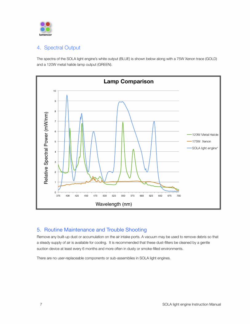
4. Spectral Output
The spectra of the SOLA light engine’s white output (BLUE) is shown below along with a 75W Xenon trace (GOLD)
and a 120W metal halide lamp output (GREEN).
5. Routine Maintenance and Trouble ShootingRemove any built-up dust or accumulation on the air intake ports. A vacuum may be used to remove debris so that
a steady supply of air is available for cooling. It is recommended that these dust-filters be cleaned by a gentle
suction device at least every 6 months and more often in dusty or smoke-filled environments.
There are no user-replaceable components or sub-assemblies in SOLA light engines.
7 SOLA light engine Instruction Manual

6. Customer Support
T: 503.505.6985
W: http://www.lumencor.com/support/software_control
M: Lumencor, Inc., 14964 NW Greenbrier Parkway, Beaverton, OR 97006 U.S.A.
7. Product Specifications
The SOLA must be operated and stored within the environmental conditions specified.
8 SOLA light engine Instruction Manual
Specification Detail
Temperature
Operating 32 to 95° F (0 to 35° C)
Non-operating -4 to 158° F (-20 to 70° C)
Humidity
Operating and non-operating 0 to 80% relative humidity, non-condensing
Altitude
Operating 0 to 10,000 feet (3,048 meters)
Non-operating 0 to 20,000 feet (6,096 meters)
Dimensions (LxWxH) 11.0 x 7.0 x 4.0 in / 27.9 x 17.8 x 10.2 cm
Weight 9 lb / 4.1 kg
Lifetime > 15,000 hr
Input Power Requirements 24-30 VDC / 7.9A
Warm-up Period Less than 1 minute
Protection IP Rating of X0
Sound Level Sound Level at 1 meter < 65db(A)
Connectivity RS-232, USB
Warranty 36 months parts and labor for end users

8. Connectors
8.2 RS-232 Connector This port conforms to standard RS-232 Interface Protocol.
DB9 Connector Pin Definitions
9. Declaration of Conformance
Manufacturer: Lumencor, Inc.
14964 NW Greenbrier Parkway, Beaverton, OR 97006 USA
We declare under our sole responsibility that the SOLA Light Engine conforms to the following directives and norms:
EMC directive 2004/108/EC
2006/95/EC
CB Scheme
CE Declaration of Conformity
TUV NRTL Listing
TUV Canadian Listing
TUV European License
10. WarrantyThe SOLA light engine is backed by a 36 month warranty to end users.
9 SOLA light engine Instruction Manual
Pins Definition DC Characteristics
1, 2, 3, 4, 6, 7, 8DCD, RXD, TXD, DTR, D3R, RTS, CTS
VCC = 5.0V, Vilow (max) = 0.8V, Vihigh (min) = 2.4V, Iilow = 0.5mA, Iihigh = 1.0μA
5 Gnd
9 N/C


