Notes on Liquid CoolingThe cold plate of the water heat exchanger on the Model 3300B contains microchannels as small as 0.1 mm in size. The inlet water supply
must use an inline filter with a 30 micron rating to avoid creating obstructions within the microchannels. The minimum flow rate must
be 1.5 liters/min. An ideal water flow rate is 3 liters/min. A recirculating chiller with an inlet water temperature maintained at or below
o p t i o n s : (Please contact IOI to specify a final configuration and for pricing)
Wavelengths: Four different center wavelengths are available with nominal spectral power distributions as plotted in Figure 5. The center wavelengths are within 5 nm of the following: 365 nm, 385 nm, 395 nm, 405 nm. Single or multiple wavelength configurations can be arranged.
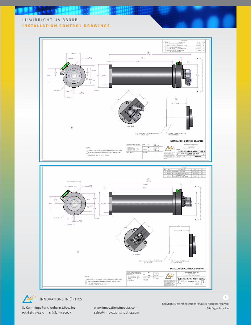
Hose Connections: The standard configuration uses hose connections aligned at a right-angle to the illu-minator body as shown in the Interface Control Drawings. An optional configuration features hose connections that are in line with the illuminator body.
* Failure to use the 5500A Driver/Controller or an inline water filter would void our warranty.
Multi-Channel:
The IOI Model 5500A is a multi-channel OEM Driver/Controller with Ethernet and USB. The driver provides independent current control to each of the LED die to achieve optimal performance and lifetime.
Up to 18-die in the UV-LED array can be driven and modulated independently for precise exposure control in direct imaging systems. A command set is provided for user programming.
The 5500A has been specially designed to ensure maximum output and lifetime from Innovations in Optics’ LumiBright 3300B UV-LED Illuminators by ensuring uniform current density through the entire LED array.
d r i v e r / c o n t r o l l e r
Model Number DLP Chipset LED Array Die Count Cooler Type
All 3300B illuminators provide a kinematic type interface for accurate positional and angular registration to the DLP chipset. The mounting flange features a flat surface, a hole and a slot. The flange must mate to a flat surface on the DLP chipset housing which also must include two pins for the hole and slot. This ensures that the illuminator and housing always mate correctly. The pin-to-hole locks position and the pin-to-slot locks rotation.
In addition, when using the mounting flange, illumination overfill of the DLP active area designed into the telecentric optics relaxes positional and transverse tolerances along the optical axis.
tir prisms
Adding a TIR prism to the telecentric illumination enables a compact, on-axis design that minimizes field size and ensures a high degree of uniformity across the entire field. In addition, a TIR prism separates the illumination and projection axes so that the telecentric condition also produces uniform distribution of angles of incidence across the antireflection (AR) coated surfaces of the DLP chipset window to avoid spatial non-uniformities in projected brightness due to coating-performance variation with angle of incidence.
A TIR prism behaves optically as a thick, flat glass plate that elongates the optical path length (OPL) to theillumination plane. The ICD drawings specify the optical path length for a fused silica TIR prism with arefractive index of 1.46 and an OPL of 44.8 mm.
The products, their specifications and other information appearing in this document are subject to change by Innovations in Optics, Inc. (IOI) without notice. IOI assumes no liability for errors that may appear in this document, and no liability otherwise arising from the application or use of the prod-uct or information contained herein. None of the information provided herein should be considered to be a representation of the fitness or suitability of the product for any particular application or as any other form of warranty. IOI product warranties are limited to only such warranties as accompany a purchase contract or purchase order for such products. Nothing herein is to be construed as constituting an additional warranty. No information con-tained in this publication may be considered as a waiver by IOI of any intellectual property rights that IOI may have in such information. LumiBright™ is a trademark of IOI, all rights reserved. This product is protected by U.S. Patents , Patented in the U.S. and other countries.
DLP® and the DLP logo are registered trademarks of Texas Instruments.
i n s t a l l a t i o n c o n t r o l d r a w i n g s
2X 45.90
48.08
34.000
31.8
4.50
24.04
2X 24.04 3.00+ 0.020.00
3.00+ 0.020.00
4X 4.50 2X R
26.05
52.09
2X 30.0
76.0
10.0
58.0
199.5
76.0
239.6
274 MAX
A
A
4A
40.0 85.5
VIEW A-A
50.41
65.21
NOMINAL ILLUMINATION PLANEWITHOUT TIR PRISM
2 3 NOMINAL ILLUMINATION PLANE WITH TIR PRISM
NOTES:
1. CONTENT FOR REFERENCE ONLY AND SUBJECT TO CHANGE
2 FUSED SILICA TIR PRISM WITH EQUIVALENT 44.8 THICKNESS
3 INCLUDES EFFECT OF DMD WINDOW
INSTALLATION CONTROL DRAWING
3A
4B
REVISIONSREV ECN DESCRIPTION DATE ENG
2 E-00010 REDESIGNED & REDRAWN 6/21/2016 BG
3 E-00034 A) ADDED MISSING DIMENSIONS 12/1/2016 SFS
4 E-00050 A) 274 MAX WAS 271 MAXB) DELETE J1 & J2 CONN DETAIL 1/20/2017 BG
DATE
TITLE
SIZEC
SHEET 1 of 1
REVDWG. NO.FINISH:
4
DRW
ENG
ENG APVD
MATERIAL:
UNLESS OTHERWISE SPECIFIED:DIMENSIONS ARE IN MILLIMETERSTOLERANCES:
1 PLACE DECIMAL: 0.22 PLACE DECIMALS: 0.103 PLACE DECIMALS: 0.050ANGLE: 1
THIS DRAWING AND SPECIFICATIONSHEREIN ARE THE PROPERTY OF INNOVATIONS IN OPTICS, INC. AND SHALL NOT BE REPRODUCED NOR COPIED NOR USED IN WHOLE OR IN PART AS THE BASIS FOR THE MANUFACTURE OR SALE OF ITEMS WITHOUT THE EXPRESS WRITTEN PERMISSION OF INNOVATIONS IN OPTICS, INC.
TEL: (781) 933-4477 FAX: (781) 933-0007
82 Cummings ParkWoburn, MA 01801
Innovations in Optics, Inc.
ILLUMINATOR ASSY, TYPE 33300B-621-ICD
SCALE: 1:1
BG
BG
TB
9/6/2015DATE
DATE9/6/2015
9/6/2015
Plot
Dat
e: F
rida
y, J
anua
ry 2
0, 2
017
Las
t Sav
ed F
rida
y, J
anua
ry 2
0, 2
017
7:09
:20
PM b
y: 7
510-
1
2X 45.90
48.08
34.000
31.8
4.50
24.04
2X 24.04 3.00+ 0.020.00
3.00+ 0.020.00
4X 4.50 2X R
26.05
52.09
2X 30.0
76.0
10.0
58.0
199.5
76.0
239.6
272 MAX
A
A4A
5A
40.0 85.5
VIEW A-A
50.41
65.21
NOMINAL ILLUMINATION PLANEWITHOUT TIR PRISM
2 3 NOMINAL ILLUMINATION PLANE WITH TIR PRISM
NOTES:
1. CONTENT FOR REFERENCE ONLY AND SUBJECT TO CHANGE
2 FUSED SILICA TIR PRISM WITH EQUIVALENT 44.8 THICKNESS
3 INCLUDES EFFECT OF DMD WINDOW
INSTALLATION CONTROL DRAWING
3A
4B
REVISIONSREV ECO NO DESCRIPTION DATE ENG
2 E-00010 REDESIGNED & REDRAWN 6/21/2016 BG
3 E-00034 A) ADDED MISSING DIMENSIONS 12/1/2016 SFS
5 E-00077 A) 272 MAX WAS 281 MAXB) PICTORIAL UPDATE 5/13/2017 BG
DATE
TITLE
SIZEC
SHEET 1 of 1
REVDWG. NO.FINISH:
5
DRW
ENG
ENG APVD
MATERIAL:
UNLESS OTHERWISE SPECIFIED:DIMENSIONS ARE IN MILLIMETERSTOLERANCES:
1 PLACE DECIMAL: 0.22 PLACE DECIMALS: 0.103 PLACE DECIMALS: 0.050ANGLE: 1
THIS DRAWING AND SPECIFICATIONSHEREIN ARE THE PROPERTY OF INNOVATIONS IN OPTICS, INC. AND SHALL NOT BE REPRODUCED NOR COPIED NOR USED IN WHOLE OR IN PART AS THE BASIS FOR THE MANUFACTURE OR SALE OF ITEMS WITHOUT THE EXPRESS WRITTEN PERMISSION OF INNOVATIONS IN OPTICS, INC.
i n s t a l l a t i o n c o n t r o l d r a w i n g s
2X 45.90
48.08
34.000
31.8
4.50
24.04
2X 24.04 3.00+ 0.020.00
3.00+ 0.020.00
4X 4.50 2X R
26.05
52.09
2X 30.0
76.0
10.0
58.0
199.5
76.0
239.6
274 MAX
A
A
4A
40.0 85.5
VIEW A-A
50.41
65.21
NOMINAL ILLUMINATION PLANEWITHOUT TIR PRISM
2 3 NOMINAL ILLUMINATION PLANE WITH TIR PRISM
NOTES:
1. CONTENT FOR REFERENCE ONLY AND SUBJECT TO CHANGE
2 FUSED SILICA TIR PRISM WITH EQUIVALENT 44.8 THICKNESS
3 INCLUDES EFFECT OF DMD WINDOW
INSTALLATION CONTROL DRAWING
3A
4B
REVISIONSREV ECN DESCRIPTION DATE ENG
2 E-00010 REDESIGNED & REDRAWN 6/21/2016 BG
3 E-00034 A) ADDED MISSING DIMENSIONS 12/1/2016 SFS
4 E-00050 A) 274 MAX WAS 271 MAXB) DELETE J1 & J2 CONN DETAIL 1/20/2017 BG
DATE
TITLE
SIZEC
SHEET 1 of 1
REVDWG. NO.FINISH:
4
DRW
ENG
ENG APVD
MATERIAL:
UNLESS OTHERWISE SPECIFIED:DIMENSIONS ARE IN MILLIMETERSTOLERANCES:
1 PLACE DECIMAL: 0.22 PLACE DECIMALS: 0.103 PLACE DECIMALS: 0.050ANGLE: 1
THIS DRAWING AND SPECIFICATIONSHEREIN ARE THE PROPERTY OF INNOVATIONS IN OPTICS, INC. AND SHALL NOT BE REPRODUCED NOR COPIED NOR USED IN WHOLE OR IN PART AS THE BASIS FOR THE MANUFACTURE OR SALE OF ITEMS WITHOUT THE EXPRESS WRITTEN PERMISSION OF INNOVATIONS IN OPTICS, INC.
TEL: (781) 933-4477 FAX: (781) 933-0007
82 Cummings ParkWoburn, MA 01801
Innovations in Optics, Inc.
ILLUMINATOR ASSY, TYPE 63300B-651-ICD
SCALE: 1:1
BG
BG
TB
9/6/2015DATE
DATE9/6/2015
9/6/2015
Plot
Dat
e: F
rida
y, J
anua
ry 2
0, 2
017
Las
t Sav
ed F
rida
y, J
anua
ry 2
0, 2
017
7:11
:05
PM b
y: 7
510-
1
2X 45.90
48.08
34.000
31.8
4.50
24.04
2X 24.04 3.00+ 0.020.00
3.00+ 0.020.00
4X 4.50 2X R
26.05
52.09
2X 30.0
3A
76.0
10.0
58.0
199.5
76.0
239.6
272 MAX
A
A4A
5A
40.0 85.5
VIEW A-A
50.41
65.21
NOMINAL ILLUMINATION PLANEWITHOUT TIR PRISM
2 3 NOMINAL ILLUMINATION PLANE WITH TIR PRISM
NOTES:
1. CONTENT FOR REFERENCE ONLY AND SUBJECT TO CHANGE
2 FUSED SILICA TIR PRISM WITH EQUIVALENT 44.8 THICKNESS
5 E-00077 A) 272 MAX WAS 281 MAXB) PICTORIAL UPDATE 5/13/2017 BG
DATE
TITLE
SIZEC
SHEET 1 of 1
REVDWG. NO.FINISH:
5
DRW
ENG
ENG APVD
MATERIAL:
UNLESS OTHERWISE SPECIFIED:DIMENSIONS ARE IN MILLIMETERSTOLERANCES:
1 PLACE DECIMAL: 0.22 PLACE DECIMALS: 0.103 PLACE DECIMALS: 0.050ANGLE: 1
THIS DRAWING AND SPECIFICATIONSHEREIN ARE THE PROPERTY OF INNOVATIONS IN OPTICS, INC. AND SHALL NOT BE REPRODUCED NOR COPIED NOR USED IN WHOLE OR IN PART AS THE BASIS FOR THE MANUFACTURE OR SALE OF ITEMS WITHOUT THE EXPRESS WRITTEN PERMISSION OF INNOVATIONS IN OPTICS, INC.