078-1060-01A This guide introduces the LumInsight Web Portal dashboard. Use this guide to set up Geozones, update and delete devices, manage alarms, manage group con- trollers, manage FPMs, and troubleshoot your Geozones. LumInsight Web Portal User’s Guide
Transcript
078-1060-01A
This guide introduces the LumInsight Web Portal dashboard. Use this guide to set up Geozones, update and delete devices, manage alarms, manage group con-trollers, manage FPMs, and troubleshoot your Geozones.
LumInsight Web Portal User’s Guide
Echelon, LumeWave, LumInsight, and the Echelon logo are trademarks of Echelon Corporation that may be registered in the United States and other countries.
Other brand and product names are trademarks or registered trademarks of their respective holders.
Neuron Chips and other OEM Products were not designed for use in equipment or systems, which involve danger to human health or safety, or a risk of property damage and Echelon assumes no responsibility or liability for use of the Neuron Chips in such applications.
Parts manufactured by vendors other than Echelon and referenced in this document have been described for illustrative purposes only, and may not have been tested by Echelon. It is the responsibility of the customer to determine the suitability of these parts for each application.
ECHELON MAKES AND YOU RECEIVE NO WARRANTIES OR CONDITIONS, EXPRESS, IMPLIED, STATUTORY OR IN ANY COMMUNICATION WITH YOU, AND ECHELON SPECIFICALLY DISCLAIMS ANY IMPLIED WARRANTY OF MERCHANTABILITY OR FITNESS FOR A PARTICULAR PURPOSE.
No part of this publication may be reproduced, stored in a retrieval system, or transmitted, in any form or by any means, electronic, mechanical, photocopying, recording, or otherwise, without the prior written permission of Echelon Corporation.
Welcome This guide walks you through the LumInsight Web Portal.
Audience This manual shows you the dashboard of the LumInsight Web Portal. Use this guide to set up Geozones, update and delete devices, manage alarms, manage group controllers, manage FPMs, and troubleshoot your Geozones.
Updated Information For the most up-to-date information about this product, go to the Echelon Web site and search for the LumeWave product page.
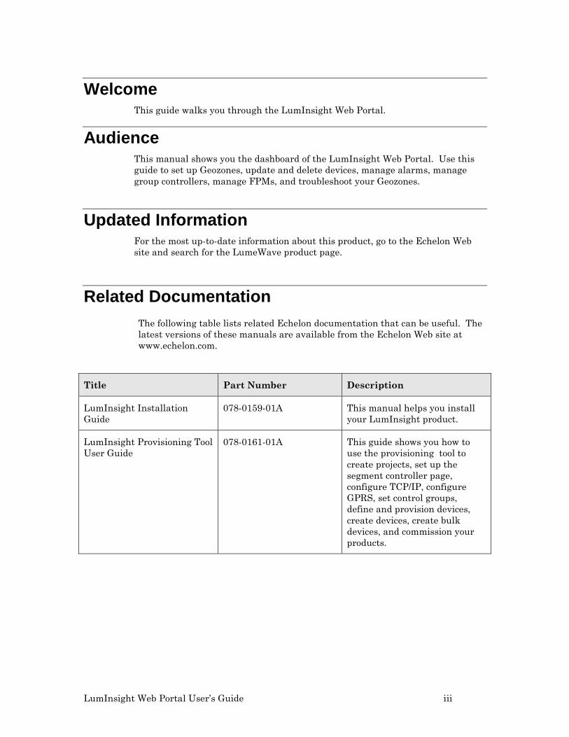
Related Documentation The following table lists related Echelon documentation that can be useful. The latest versions of these manuals are available from the Echelon Web site at www.echelon.com.
Title Part Number Description
LumInsight Installation Guide
078-0159-01A This manual helps you install your LumInsight product.
LumInsight Provisioning Tool User Guide
078-0161-01A This guide shows you how to use the provisioning tool to create projects, set up the segment controller page, configure TCP/IP, configure GPRS, set control groups, define and provision devices, create devices, create bulk devices, and commission your products.
iv
LumInsight Web Portal User’s Guide v
Table of Contents Welcome ......................................................................................................... iii Audience ........................................................................................................ iii Updated Information .................................................................................... iii Related Documentation ................................................................................ iii
Introduction to LumInsight Web Portal ..................................................... 1 Getting Started .............................................................................................. 2
Real Time Device Control ............................................................................. 29 Real Time Controlling .................................................................................. 30
Select Geozone ................................................................................. 33 Filter Devices in Map ...................................................................... 33 Real Time Controlling in View Devices ......................................... 34 Reading Device Information ........................................................... 35 Define a Scene ................................................................................. 36 Alarm Management ........................................................................ 37 Alarm Parameters ........................................................................... 38 Create Alarm ................................................................................... 39 Update Alarm .................................................................................. 41 Delete Alarm ................................................................................... 41 Alarm Failure .................................................................................. 41 Active Alarms .................................................................................. 42
Scheduler Management ................................................................................. 45 Scheduler Management Menu .................................................................... 46
User Management ........................................................................................ 70 Create User ..................................................................................... 71 Update User .................................................................................... 72
Query Status ................................................................................... 76 Test Devices ..................................................................................... 77 Poll Statistics................................................................................... 78 Button .............................................................................................. 79 Name ................................................................................................ 79 Description....................................................................................... 79 Poll Statistics................................................................................... 79 Poll Trigger ...................................................................................... 79 Operation Statistics ........................................................................ 81 Fault Statistics ................................................................................ 81 Apply the fault data configuration. ................................................ 81 Dashboard Statistics ....................................................................... 81 Data History .................................................................................... 82 Failures ............................................................................................ 83 Group Controller Screen ................................................................. 84
Reports .......................................................................................................... 84 Failure Analysis .............................................................................. 85 Display the Aggregated Failure Report for a Selected Geozone .. 86 Display the Detailed Failure Report for a Selected Geozone ....... 87 Failure Tracking ............................................................................. 87 Aggregated Number of Failures per Geozone ............................... 88 Display Faulty Devices on a Map .................................................. 88 Energy History ................................................................................ 89
LumInsight Web Portal User’s Guide 1
1
Introduction to LumInsight Web Portal
The LumInsight Web Portal is the access point for LumInsight software. This guide explains the graphical user interface to LumInsight.
2 Introduction to LumInsight Web Portal
Getting Started To access the LumInsight Web portal, type the IP address in your browser and press Enter. This opens the LumInsight login screen. LumInsight is supported in IE8+ or higher, Mozila Firefox, and Google Chrome.
Figure 1. LumInsight Login Screen Use this screen to enter your user name and password to log in to the portal. The page includes a ‘remember me’ box and a prompt in case you forget your password. Once you log in, the LumInsight Dashboard is available. Now you can see your geozone and access information about it.
Figure 2. Dashboard
LumInsight Web Portal User’s Guide 3
Dashboard Across the top of the Dashboard are four boxes.
Box Description
Blue Box
Displays the total number of Geozones.
Green Box
Displays the number of devices in all Geozones.
Grey Box
Displays the total number of unconfigured devices in all Geozones.
Yellow Box
Displays the total number of inactive devices in all Geozone.
System Information To access LumInsight system version information from your Dashboard, click the System Information button. Figure 3 shows the information screen.
Figure 3. System Information
4 Introduction to LumInsight Web Portal
Geozone Wise Energy Usage A Geozone is used to partition the hierarchy of the assets in the system. A Geozone can have multiple subGeozones.
Using the Green Box widget, you can access Daily, Weekly, and Monthly energy usage. The following figures show examples of each usage.
Figure 4. Geozone Wise Energy Daily Usage
Figure 5. Geozone Wise Energy Weekly Usage
LumInsight Web Portal User’s Guide 5
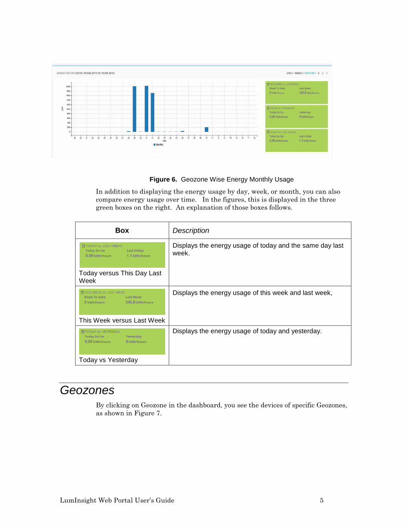
Figure 6. Geozone Wise Energy Monthly Usage
In addition to displaying the energy usage by day, week, or month, you can also compare energy usage over time. In the figures, this is displayed in the three green boxes on the right. An explanation of those boxes follows.
Box Description
Today versus This Day Last Week
Displays the energy usage of today and the same day last week.
This Week versus Last Week
Displays the energy usage of this week and last week,
Today vs Yesterday
Displays the energy usage of today and yesterday.
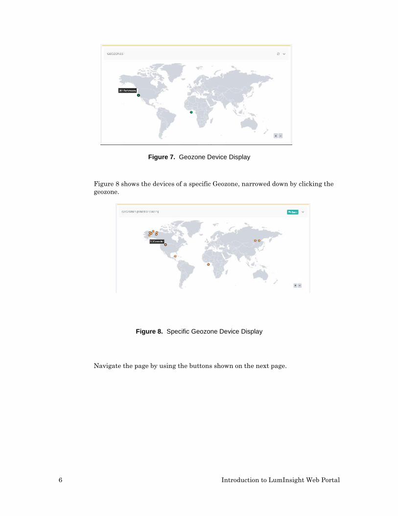
Geozones By clicking on Geozone in the dashboard, you see the devices of specific Geozones, as shown in Figure 7.
6 Introduction to LumInsight Web Portal
Figure 7. Geozone Device Display
Figure 8 shows the devices of a specific Geozone, narrowed down by clicking the geozone.
Figure 8. Specific Geozone Device Display
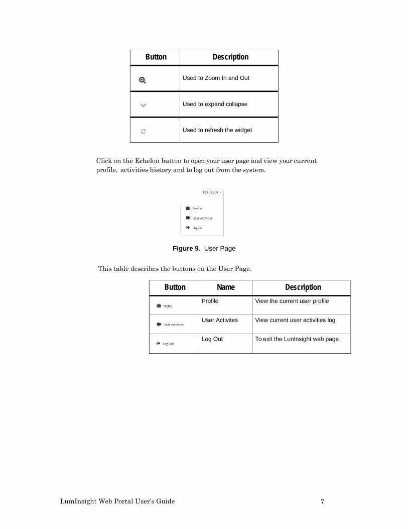
Navigate the page by using the buttons shown on the next page.
LumInsight Web Portal User’s Guide 7
Click on the Echelon button to open your user page and view your current profile, activities history and to log out from the system.
Figure 9. User Page
This table describes the buttons on the User Page.
Button Name Description
Profile View the current user profile
User Activites View current user activities log
Log Out To exit the LunInsight web page
Button Description
Used to Zoom In and Out
Used to expand collapse
Used to refresh the widget
8 Introduction to LumInsight Web Portal
GeoZone Device Display By clicking on Geozone, it will display the devices of specific Geozones as shown in Figure 7.
Profile On the Profile screen, you will see the profile information, and have a chance to change your password and change the dashboard widget display as shown in Figure 10.
Figure 10. Profile Page
You can change the widget settings on this page. If you want the widgets to display on the dashboard, click in the check box and use the Save button to activate the change.
User Activity The User Activity page displays user actions performed on the whole system, module wise. It tracks activities and is useful to find behavior that changes the system. By default, you can see the last two day’s worth of activity (module wise, as well as timing) and view other activities. The activity is displayed for only the logged in user.
LumInsight Web Portal User’s Guide 9
Figure 11. User Activity Page The User Activity page displays the user name and the gives you a button to see more activity.
Button Description
Displays the more activity
Indicates user name
Asset Management Under the Asset Management selections, you can create Geozones, update your devices, and delete and view areas under your logged in Geozones and their descendant Geozones.
10 Introduction to LumInsight Web Portal
Geozones Figure 12 shows the screen where you manage your Geozones.
Figure 12. Manage Geozones Use the buttons on the page to select the Geozone you want to manage.
Button Name Description
Create Geozone Create a new Geozone
View Area View existing Geozone area
Update Geozone Edit existing Geozone
Delete Delete Geozone
LumInsight Web Portal User’s Guide 11
Create a Geozone Click on the Create Geozone button to open the screen where you can create a new Geozone.
Figure 13. Create Geozone
Geozone Tree By selecting the Geozone from the Geozone tree it will display in the LumInsight system page. Changes at the Geozone tree will change in the LumInsight system page. All changes here will reflect in LumInsight.
Select Geozone Area
Name: Enter name of Geozone.
Parent Geozone: Select Parent Geozone
NorthEast Latitiude: entered here
NorthEast Longitude: entered here
SouthEast Latitude: entered here
SouthEast Longitude: entered here
Click the Save button to add your new Geozone. Click on the button to draw Geozone areas, as shown in Figure 14.
12 Introduction to LumInsight Web Portal
Select Geozone Area Use this screen to choose the area for your Geozone.
Figure 14. Geozone Area
The buttons on the Select Geozone Area screen are described below.
Table 1-7. Select Geozone Area Button Description Button Name Description
Search Allows to search from map
Zoom Allows to zoom In and Out of map
- Different types of Map
- Draw area of geozone
This is where you use LumInsight to draw the area that will include your Geozone and click on Submit – this adds in NorthEast Latitude, NorthEast Longitude, SouthWest Latitude, and SouthWest Longitude.
LumInsight Web Portal User’s Guide 13
Geozone Wise Faulty Devices Widget The Dashboard includes a widget to display any faulty devices in your Geozone, if they exist. Move your mouse across the pie and if there is a faulty device, it will display in the screen. Figure 15 shows an example of the widget.
Figure 15. Geozone Wise Faulty Devices Widget
If you click on the icon at the top of the screen, you can select the Geozone where you want to check for faulty devices.
Geozone Wise Device Status Widget This widget, also on the Dashboard, describes the number of devices and their status under your Geozone login, Move your mouse across the pie and popups will describe the number of active devices, inactive devices, and unconfigured
devices in the Geozone. By clicking on the icon at the top of the screen, you can select the Geozone where you want to check a status. Figure 15 shows the Device Status widget.
Figure 16. Geozone Wise Device Status Widget
14 Introduction to LumInsight Web Portal
Devices Now that your Geozone has been created, you can edit, delete, and view your devices (Devices + Controller) in this Geozone. Only the Geozone information associated with the login user will display.
Figure 17. Manage Devices
The information on this screen is explained below.
Button Description
This is your Geozone tree. By selecting the geozone from the geozone tree. It will display in LUMINSIGHT system pages. By changing the Geozone from the Geozone tree. It will change in LUMINSIGHT system pages.
Update an existing device
Delete device
Delete Segment Controller (with all references) if you are an admin.
View device details
LumInsight Web Portal User’s Guide 15
Update Device Click on the Update an Existing Device button to edit a device.
Figure 18. Edit Device
On the Device Information tab, you can enter the name of the device or controller (a controller is also one type of a device). You can add the Geo Location at this screen, as well. Click on the icon for a pictorial representation of a device. Then add the device to the map, as shown in Figure 19.
Figure 19. Add Device in Map
Latitude and Longitude will automatically add when you draw your device in the map and click the Submit button. Once the device is there, click Save.
16 Introduction to LumInsight Web Portal
Figure 20. Draw Device on Map
Your device is now part of your Geozone. Use the Next and Previous buttons to move forward and backward through your devices.
In these screens, under Update Device, you can also find the identity of devices. Below is a screen showing the identity of an OLC.
Figure 21. Identity for OLC
Do not change the entries from those used in the Identify dialog. The Neuron ID/Unique Address should match your Neuron ID.
Segment Controller: Select the Segment Controller
Neuron ID: Enter the Neuron ID
Device Type: Select a device type
Group Controller: Select the Group Controller
Expected Lifetime: Update the expected lifetime
Once the information is displayed, click Next. Now you can set the identity for a Segment Controller.
LumInsight Web Portal User’s Guide 17
Figure 22. Identity for Segment Controller
When you identify a Segment Controller, the following fields are mandatory.
Controller Name: Enter the name of the controller.
HostName: The host name of the controller.
Controller Technology: Select from list.
Once the information has been entered, select Device in category, and click Next. This is the screen to create the identity for a sensor (Traffic Occupancy Sensor (TOS)).
Figure 23. Identity for Sensor
Just like the Segment Controller screen, all fields here are mandatory.
Segment Controller: Select the segment controller name.
NeuronID: Enter the Neuron ID.
Device Type: Select the device type from a list.
18 Introduction to LumInsight Web Portal
Continue in Update Device arena and select Device in the category and click next. You will now enter Inventory information to support your devices. In this example, the device is a lamp.
Figure 24. Inventory for OLC
Fill out the fields of this screen.
Lamp Type: Select the lamp type.
Baseline Power: Enter the baseline power.
Fixture Model: Enter the fixture model.
Datasheet URL: Enter the datasheet URL.
Installed Date: Select the installation date.
Service Notes: Optional, enter the service information of your choice.
Click on the Update button to update your device.
Now click Segment Controller and click on Next. The next figure shows the inventory for the Segment Controller.
Figure 25. Inventory for Segment Controller
LumInsight Web Portal User’s Guide 19
Fill out the following fields for the controller.
Cabinet Type: Select a cabinet type.
Address: Enter the address.
Installed Date: Select the installed date.
Comment: Optional.
Click on the Update button to update your controller.
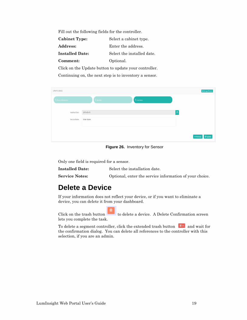
Continuing on, the next step is to inventory a sensor.
Figure 26. Inventory for Sensor
Only one field is required for a sensor.
Installed Date: Select the installation date.
Service Notes: Optional, enter the service information of your choice.
Delete a Device If your information does not reflect your device, or if you want to eliminate a device, you can delete it from your dashboard.
Click on the trash button to delete a device. A Delete Confirmation screen lets you complete the task.
To delete a segment controller, click the extended trash button and wait for the confirmation dialog. You can delete all references to the controller with this selection, if you are an admin.
20 Introduction to LumInsight Web Portal
Device Details
Figure 27 shows the details for a controller.
Figure 27. View Details of Category Type – Device
You can select the More Info button at the top of the screen to see further information for your device.
Figure 28. More Information
In addition to viewing the details of a device, you can use the same steps to view details of a sensor or a controller. Figures 29 and 30 show you detailed views of both.
LumInsight Web Portal User’s Guide 21
Figure 29. Detailed View of Sensor
Figure 30. Detailed View of Segment Controller
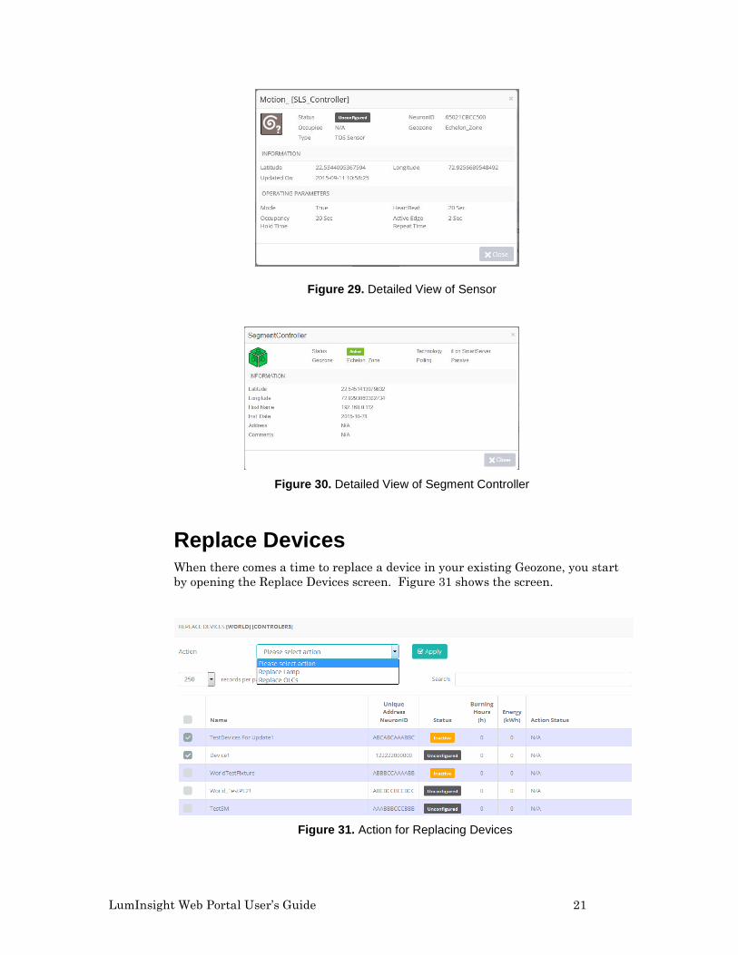
Replace Devices When there comes a time to replace a device in your existing Geozone, you start by opening the Replace Devices screen. Figure 31 shows the screen.
Figure 31. Action for Replacing Devices
22 Introduction to LumInsight Web Portal
You can replace a lamp or an OLC from this screen. Simply select the action from the menu and move on to the next screen. For this example, we will select an OLC.
Figure 32. Replace OLC
Enter the information to support the replacement device: a name, NeuronID, and New Unique Address.
Manage Geopositioning The replaced device needs to be placed inside your Geozone. Use the following screen to update the device location of your replacement device.
Figure 33. Update Device Location
Use the following screen to update the device location of your replacement device.
This button opens the sidebar and displays the Geozone tree in it. Click on any Geozone and the devices will display in the map. Click again to close the sidebar. Click on Save to save the new position of the device. Click on the Reset button if you need to reset any of your devices.
LumInsight Web Portal User’s Guide 23
Use the Cancel button, shown above, if you want to select the area, for single or multiple devices, to change geoposition. This is shown in Figure 34.
Figure 34. Selected Area in Manage Geopositioning Screen
The pink rectangle in the map shows a series of Segment Controllers, shown above. Right click on the Segment Controller icon to view devices of the selected segment controllers and their Group Controller, as shown in Figure 35.
Figure 35. Manage Geopositioning Vew Devices
24 Introduction to LumInsight Web Portal
In this view, you cannot move the devices from the Geozone boundary. If you select the Geozone from the Geozone Tree it will display in the LumInsight system pages. Changing the Geozone from the Geozone Tree will change it in the LumInsight system pages, as well. These changes will be reflected in LumInsight.
The icons on this page are explained in the following table.
Icon Explanation
Device is in group.
Device is not in group.
Device is selected to view devices.
Export Devices You can export devices category-wise (Segment Controller and device) as well as combine them. Figure 36 shows the screen to Export Devices.
Figure 36. Export Devices
Select a Category to export the Segment Controller and device. Click on Next.
LumInsight Web Portal User’s Guide 25
Figure 37. Select Attributes
Select the attributes of the devices marked for export. Once you have made your selections, click on the Export button to export the CSV file. Then save to save the exported file, as shown below.
Figure 38. Save Exported File
Import Devices You can import devices to your Geozone. Devices and Controllers can upload from .erdp and cvs files, as well as from a download template (file format) for the upload device location. Figure 39 shows the Import Devices screen.
26 Introduction to LumInsight Web Portal
Figure 39. Import Devices
You will need to download a template in order to to complete a device upload. Click on the Download Template button (shown above) to receive the screen for this download, shown in Figure 40. Click on the Download button to access the template.
Figure 40. Template Download
Browse Files
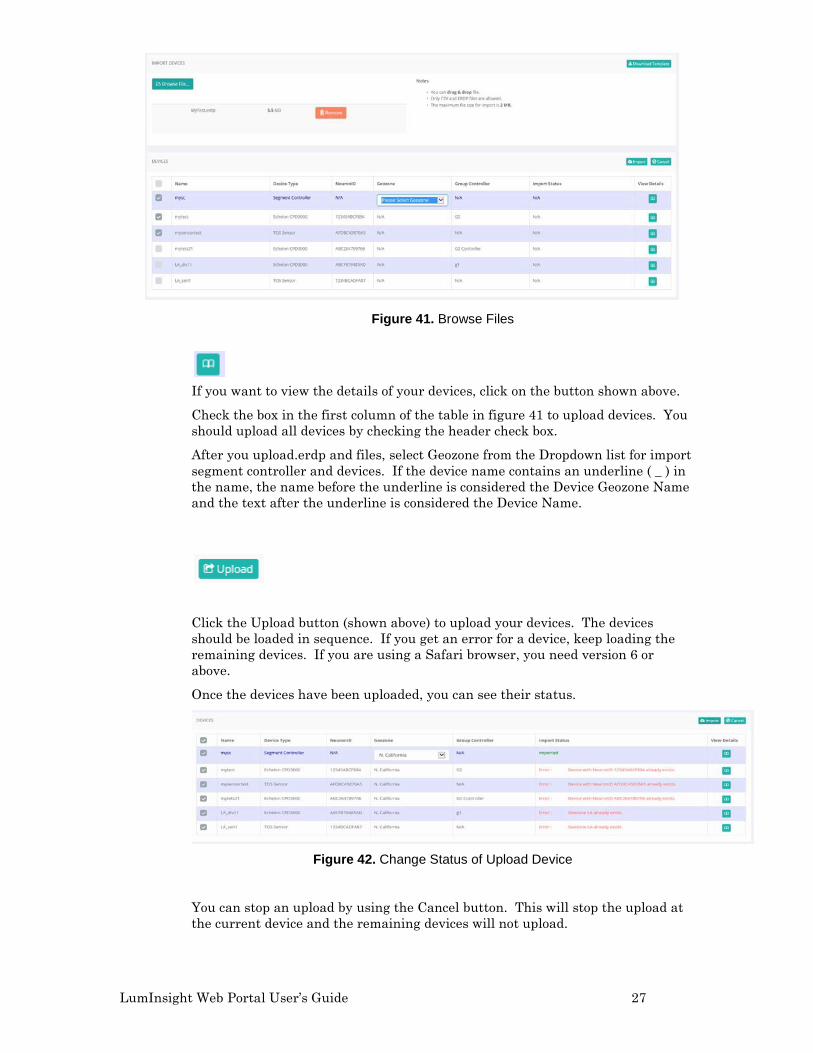
Click on the Browse Files button (shown above) to browse to a file to upload devices and for the upload location. These files are only accepted as .csv or .erdp files. Selected file contents display in a table, as shown in Figure 41.
LumInsight Web Portal User’s Guide 27
Figure 41. Browse Files
If you want to view the details of your devices, click on the button shown above.
Check the box in the first column of the table in figure 41 to upload devices. You should upload all devices by checking the header check box.
After you upload.erdp and files, select Geozone from the Dropdown list for import segment controller and devices. If the device name contains an underline ( _ ) in the name, the name before the underline is considered the Device Geozone Name and the text after the underline is considered the Device Name.
Click the Upload button (shown above) to upload your devices. The devices should be loaded in sequence. If you get an error for a device, keep loading the remaining devices. If you are using a Safari browser, you need version 6 or above.
Once the devices have been uploaded, you can see their status.
Figure 42. Change Status of Upload Device
You can stop an upload by using the Cancel button. This will stop the upload at the current device and the remaining devices will not upload.
28 Introduction to LumInsight Web Portal
Remove Files after Browse
Click on the Remove button trash can (shown above) to start the process for removing a file. A confirmation dialog box will pop up. Click on the Yes button to remove a file after browsing, as shown in Figure 43.
Figure 43. Remove File Confirmation
To find out if a device was uploaded successfully, see “Completed” in status. If any errors happened during the upload, you can display the error message. You can cancel any remaining uploading that did not take place. The status for the device will display as “Cancel”.
LumInsight Web Portal User’s Guide 29
2
Real Time Device Control
This chapter describes the steps for remotely taking control of each individual device in a Geozone.
30 Real Time Device Control
Real Time Controlling
You can control your devices to switch them ON/OFF, set dimming, read failure status of them, and see status wise filtering devices in your LumInsight map.
To control your devices, access the Control Devices screen, as shown in Figure 44.
Figure 44. Real Time Controlling
The following table shows the buttons and icons used on the Real Time Controlling screen.
Button Indication
Device is ON.
Device is OFF.
Device has dimmer 25%.
LumInsight Web Portal User’s Guide 31
Device has dimmer 50%.
Device has dimmer 75%.
Device is Inactive.
Device is Unconfigured.
Device is unknown.
Device is auto mode ON.
Device is auto mode OFF.
Device is in auto mode with dimmer 25%.
Device is in auto mode with dimmer 50%.
Device is in auto mode with dimmer 75%.
Device is in auto mode with inactive status.
32 Real Time Device Control
Device is in auto mode with unconfigured status.
Device is in auto mode with unknown status.
Segment controller is active with passive polling,
Segment controller is inactive with passive polling.
Segment controller is active with active polling.
Segment controller is inactive with active polling.
Sensor is configured.
Sensor is unconfigured.
Sensor is inactive.
Sensor is unknown.
Bridge is configured.
Bridge is inactive.
Bridge is unconfigured.
LumInsight Web Portal User’s Guide 33
Bridge is unknown.
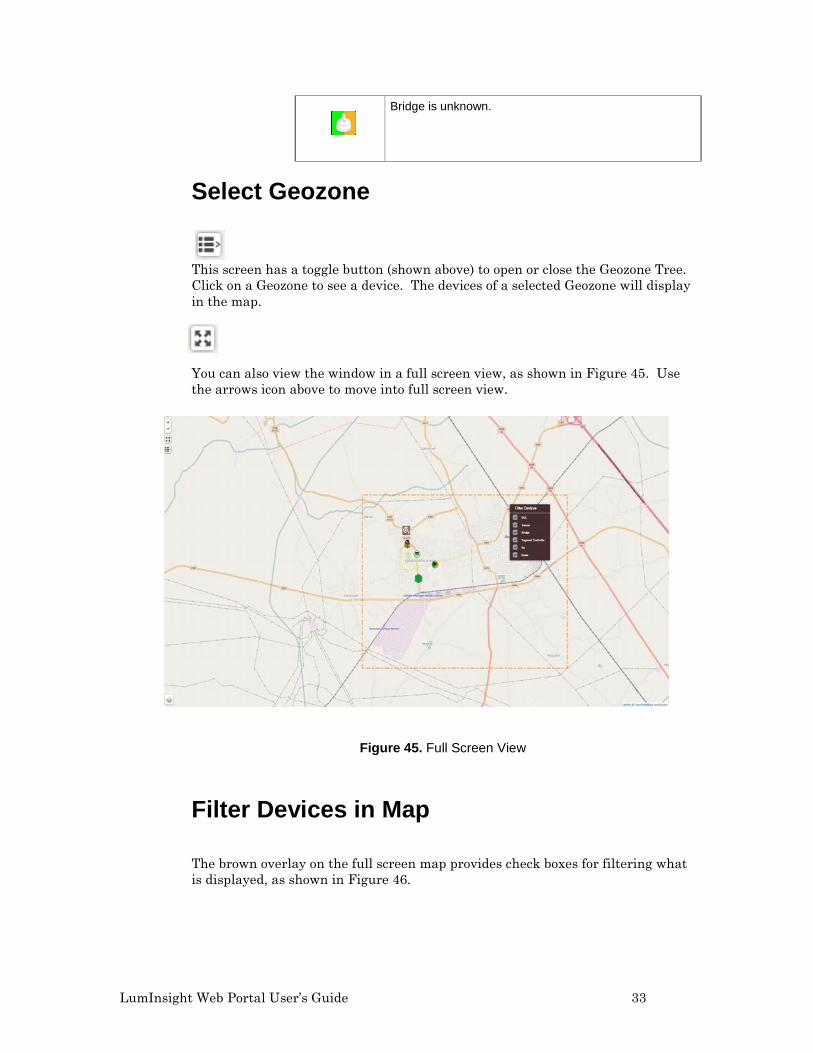
Select Geozone
This screen has a toggle button (shown above) to open or close the Geozone Tree. Click on a Geozone to see a device. The devices of a selected Geozone will display in the map.
You can also view the window in a full screen view, as shown in Figure 45. Use the arrows icon above to move into full screen view.
Figure 45. Full Screen View
Filter Devices in Map
The brown overlay on the full screen map provides check boxes for filtering what is displayed, as shown in Figure 46.
34 Real Time Device Control
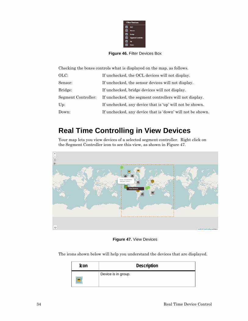
Figure 46. Filter Devices Box
Checking the boxes controls what is displayed on the map, as follows.
OLC: If unchecked, the OCL devices will not display.
Sensor: If unchecked, the sensor devices will not display.
Bridge: If unchecked, bridge devices will not display.
Segment Controller: If unchecked, the segment controllers will not display.
Up: If unchecked, any device that is ‘up’ will not be shown.
Down: If unchecked, any device that is ‘down’ will not be shown.
Real Time Controlling in View Devices Your map lets you view devices of a selected segment controller. Right click on the Segment Controller icon to see this view, as shown in Figure 47.
Figure 47. View Devices
The icons shown below will help you understand the devices that are displayed.
Icon Description
Device is in group.
LumInsight Web Portal User’s Guide 35
Device is not in group.
Device is selected to view devices.
Reading Device Information To read device information, double click in a device on the map or double click on devices in a Geozone Tree. Open the right sidebar to display information.
Here, you can read device information, failure status, set dimming, and configured devices parameters, If the selected device is a controller, information will display as shown in Figure 48.
Figure 48. Read Device Information
36 Real Time Device Control
Define a Scene In the portal, you can set a device scene. Figure 49 shows a filled out scene.
Figure 49. Scene Definition
The following buttons are shown on the scene definition screen.
Button Description
Occupancy Events
Indicates the scene is configured to respond to occupancy events.
View Devices with Scene
View existing segment controller scene definition.
Edit Scene
Edit existing segment controller scene definition.
Delete Confirm
Delete segment controller scene definition.
Click on the View Devices button, to see the devices included with the segment controller scene definition, as shown in figure 50.
LumInsight Web Portal User’s Guide 37
Figure 50. Scene Definition Configuration
Click on the Delete button to delete segment controller scene definition. When the confirmation screen appears, click Yes.
Alarm Management
Alarm management involves viewing, creating, editing, deleting, enabling, and disabling alarms for the Streetlight. The alarms must be managed when failures or unwanted data is collected from devices. Figure 51 shows the screen for managing your alarms.
Figure 51. Manage Alarms
38 Real Time Device Control
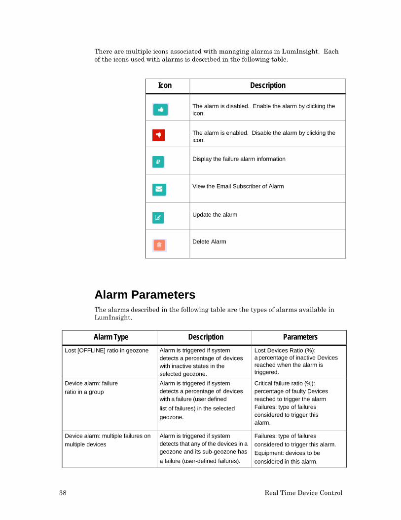
There are multiple icons associated with managing alarms in LumInsight. Each of the icons used with alarms is described in the following table.
Icon Description
The alarm is disabled. Enable the alarm by clicking the icon.
The alarm is enabled. Disable the alarm by clicking the icon.
Display the failure alarm information
View the Email Subscriber of Alarm
Update the alarm
Delete Alarm
Alarm Parameters The alarms described in the following table are the types of alarms available in LumInsight.
Alarm Type Description Parameters Lost [OFFLINE] ratio in geozone Alarm is triggered if system
detects a percentage of devices with inactive states in the selected geozone.
Lost Devices Ratio (%): apercentage of inactive Devices reached when the alarm is triggered.
Device alarm: failure ratio in a group
Alarm is triggered if system detects a percentage of devices with a failure (user defined list of failures) in the selected geozone.
Critical failure ratio (%): percentage of faulty Devices reached to trigger the alarm Failures: type of failures considered to trigger this alarm.
Device alarm: multiple failures on multiple devices
Alarm is triggered if system detects that any of the devices in a geozone and its sub-geozone has a failure (user-defined failures).
Failures: type of failures considered to trigger this alarm. Equipment: devices to be considered in this alarm.
LumInsight Web Portal User’s Guide 39
Device alarm: single alarm on multiple devices
Alarm is triggered if system detects that the number of devices with a failure (user-defined list of
failures) is above a user-defined threshold in a geozone and its subgeozones.
Failure number: threshold (number of faulty devices) above which the alarm is triggered.
Failures: type of failures considered to trigger this alarm. Equipment: devices to be considered in this alarm.
Create Alarm
Use the screen in Figure 52 to create an alarm. All alarms are generic, with parameters of one type of alarm very similar to another. The process is shown below, with each of the specific alarms called out.
Click the Create Alarm button to begin the process. The following screen will open.
Figure 52. Alarm Information
Define your alarm on this screen by filling in the fields.
Name: Name of Geozone. Geozone: Select Geozone to create alarm. Alarm Type: Select the alarm you want to create, as described above.
The Geozone and Alarm Types are required. Click on the Next button to move to the step, filling in the fields of the Failure wizard.
40 Real Time Device Control
Figure 53. Failure Wizard
Fill in all fields of the Failure screen. When you are finished, click Next to move to the Email Wizard.
Figure 54. Email Wizard
You can select more than one address for an alarm email. Click on the … button (shown above) to include users who will receive the email. A screen will open for this task.
Figure 55. Select User for Email for Alarm
LumInsight Web Portal User’s Guide 41
Continue filling out the fields for Figure 54 (email wizard) and click Save to add the Alarm.
Update Alarm Once an Alarm is already created, you can make changes via the Update Alarm screen.
If you need to update an Alarm you have already created, click on the update button (shown above).
Figure 56. Update an Alarm
Fill out the fields on this page and click Update to save your changes to the alarm.
Delete Alarm If an alarm is no longer required, you can delete it.
Click the Delete Button trash can. A confirmation dialog will appear. Click Delete to confirm the deleted Alarm.
Alarm Failure You can view Alarm status to see the failure of an alarm you created.
42 Real Time Device Control
Click on the Alarm Failure button. A status screen will display.
Figure 57. Alarm Failure
Use the Update Alarm screen to change the Alarm or the Delete Screen to delete it.
Use the Email button (shown above) to view a list of email addresses who have received mail about an alarm. The following screen contains this information.
Figure 58. Email Alarm Subscriber
The thumbs up and thumbs down icons let you enable or disable an Alarm. You need to be in edit mode to apply the actions. Click on Next to view the failure parameters of your alarm. You can check or uncheck boxes to enable or disable the alarms on the screen. Click the Update button to activate your changes.
Active Alarms You can display a list of active alarms as well as alarms that have been active in the past. You can see which alarms have been triggered in the system and acknowledged by maintenance operators. Alarm conditions are shown by selecting Manage Alarm. Only the alarms of the logged in user geozones will display.
LumInsight Web Portal User’s Guide 43
Figure 59. Manage Active Alarms
To acknowledge an active alarm, select the alarm from the display and click on the pen button (shown above). A new window opens. Enter a comment in the Comment field and click Save.
Figure 60. Set Acknowledge an Active Alarm
You can view the history of the alarms you have acknowledged. On the Manage Active Alarm screen, click the button shown above. A window opens to show the history of acknowledged alarms.
Figure 61. Set Acknowledge an Active Alarm
LumInsight Web Portal User’s Guide 45
3
Scheduler Management
This chapter describes scheduler management. You can view schedulers, group override controllers, bind devices, and update schedulers.
46 Scheduler Management
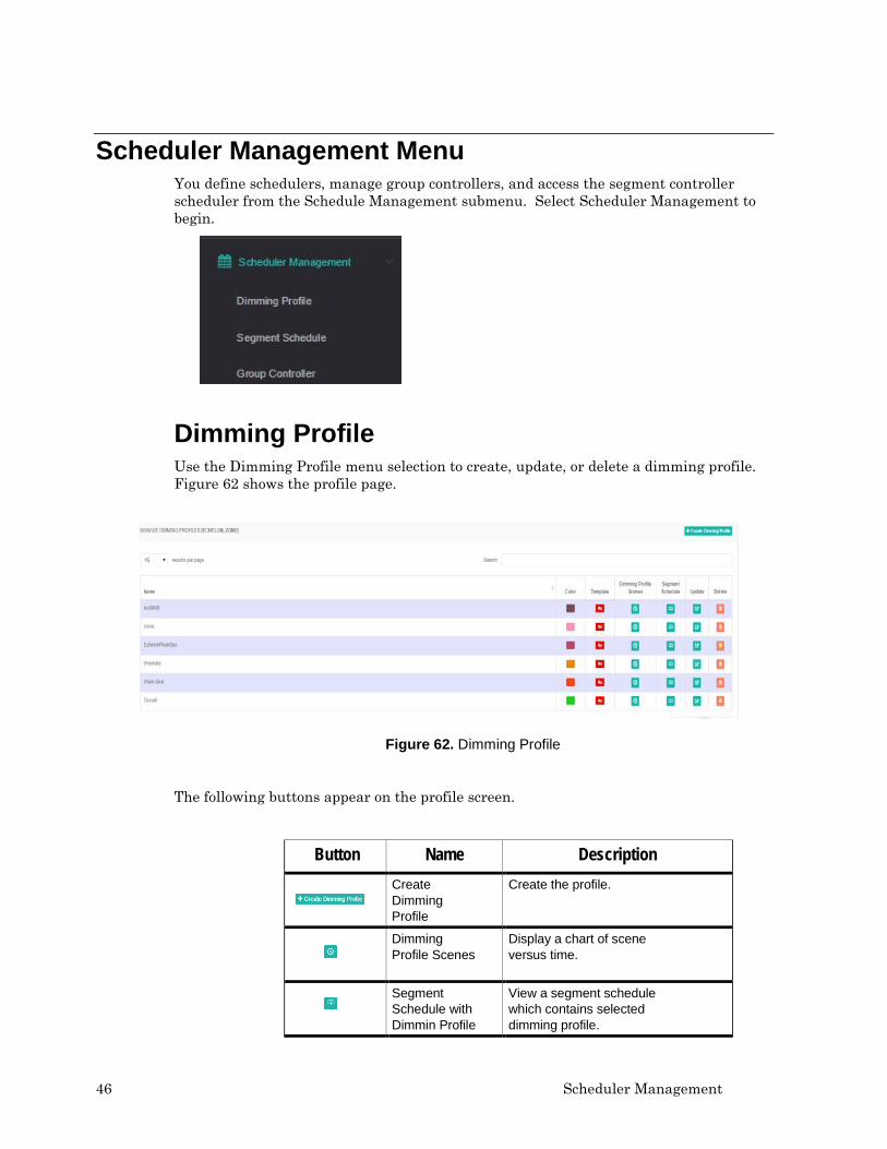
Scheduler Management Menu You define schedulers, manage group controllers, and access the segment controller scheduler from the Schedule Management submenu. Select Scheduler Management to begin.
Dimming Profile Use the Dimming Profile menu selection to create, update, or delete a dimming profile. Figure 62 shows the profile page.
Figure 62. Dimming Profile
The following buttons appear on the profile screen.
Button Name Description
Create Dimming Profile
Create the profile.
Dimming Profile Scenes
Display a chart of scene versus time.
Segment Schedule with Dimmin Profile
View a segment schedule which contains selected dimming profile.
LumInsight Web Portal User’s Guide 47
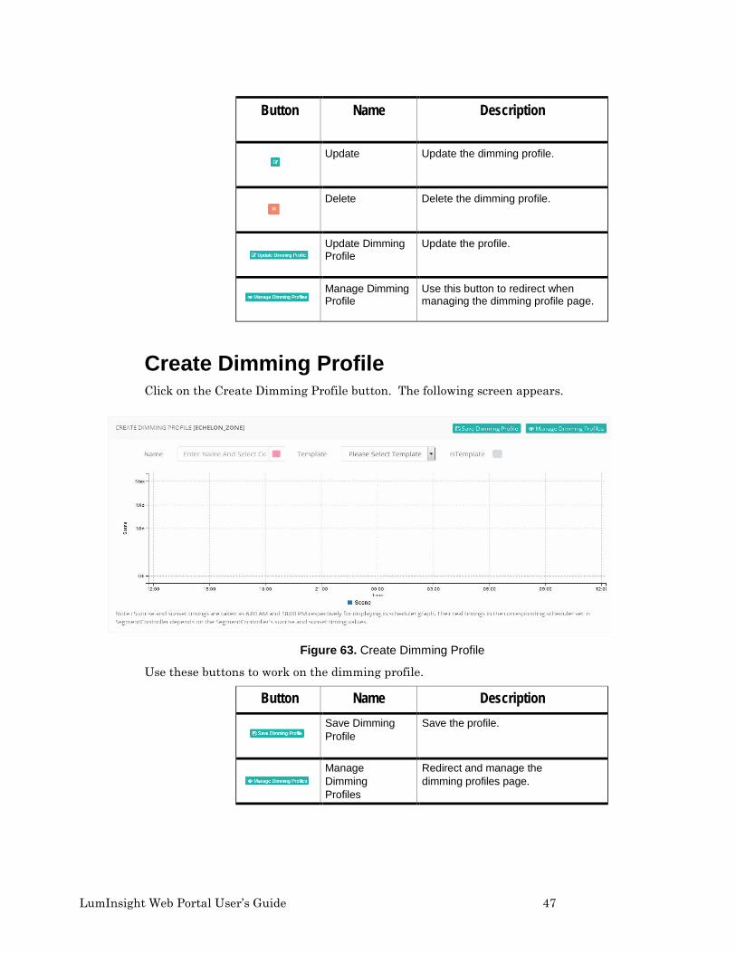
Button Name Description
Update Update the dimming profile.
Delete Delete the dimming profile.
Update Dimming Profile
Update the profile.
Manage Dimming Profile
Use this button to redirect when managing the dimming profile page.
Create Dimming Profile Click on the Create Dimming Profile button. The following screen appears.
Figure 63. Create Dimming Profile
Use these buttons to work on the dimming profile.
Button Name Description
Save Dimming Profile
Save the profile.
Manage Dimming Profiles
Redirect and manage the dimming profiles page.
48 Scheduler Management
Add Add a scene in type, time, and scene. Type selects a scheduler type. Time selects a time to display the scene. Scene selects a dimming scene for max, min, mid, and off.
Dimming Profile Scenes Click on the button to view dimming scenes versus the time chart, as shown in Figure 64.
Figure 64. Dimming Profile Scenes
Segment Schedule with Dimming Profile The second selection on the Schedule Management submenu is Segment Schedule. Click on the button to view a segment schedule with a Dimming Profile, as shown in Figure 65.
Figure 65. Segment Schedule
LumInsight Web Portal User’s Guide 49
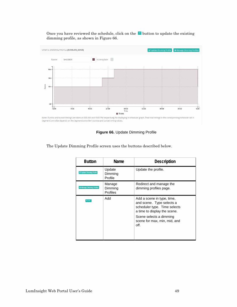
Once you have reviewed the schedule, click on the button to update the existing dimming profile, as shown in Figure 66.
Figure 66. Update Dimming Profile
The Update Dimming Profile screen uses the buttons described below.
Button Name Description
Update Dimming Profile
Update the profile.
Manage Dimming Profiles
Redirect and manage the dimming profiles page.
Add Add a scene in type, time, and scene. Type selects a scheduler type. Time selects a time to display the scene. Scene selects a dimming scene for max, min, mid, and off.
50 Scheduler Management
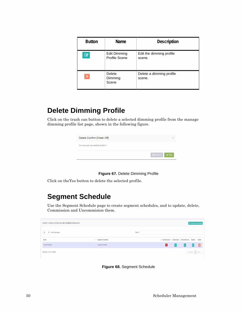
Button Name Description
Edit Dimming Profile Scene
Edit the dimming profile scene.
Delete Dimming Scene
Delete a dimming profile scene.
Delete Dimming Profile Click on the trash can button to delete a selected dimming profile from the manage dimming profile list page, shown in the following figure.
Figure 67. Delete Dimming Profile
Click on theYes button to delete the selected profile.
Segment Schedule Use the Segment Schedule page to create segment schedules, and to update, delete, Commission and Uncommision them.
Figure 68. Segment Schedule
LumInsight Web Portal User’s Guide 51
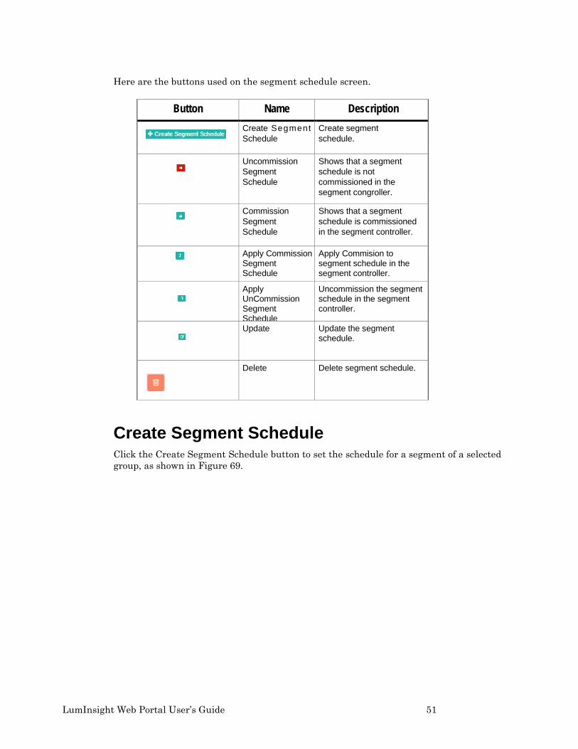
Here are the buttons used on the segment schedule screen.
Button Name Description
Create Segment Schedule
Create segment schedule.
Uncommission Segment Schedule
Shows that a segment schedule is not commissioned in the segment congroller.
Commission Segment Schedule
Shows that a segment schedule is commissioned in the segment controller.
Apply Commission Segment Schedule
Apply Commision to segment schedule in the segment controller.
Apply UnCommission Segment Schedule
Uncommission the segment schedule in the segment controller.
Update Update the segment schedule.
Delete Delete segment schedule.
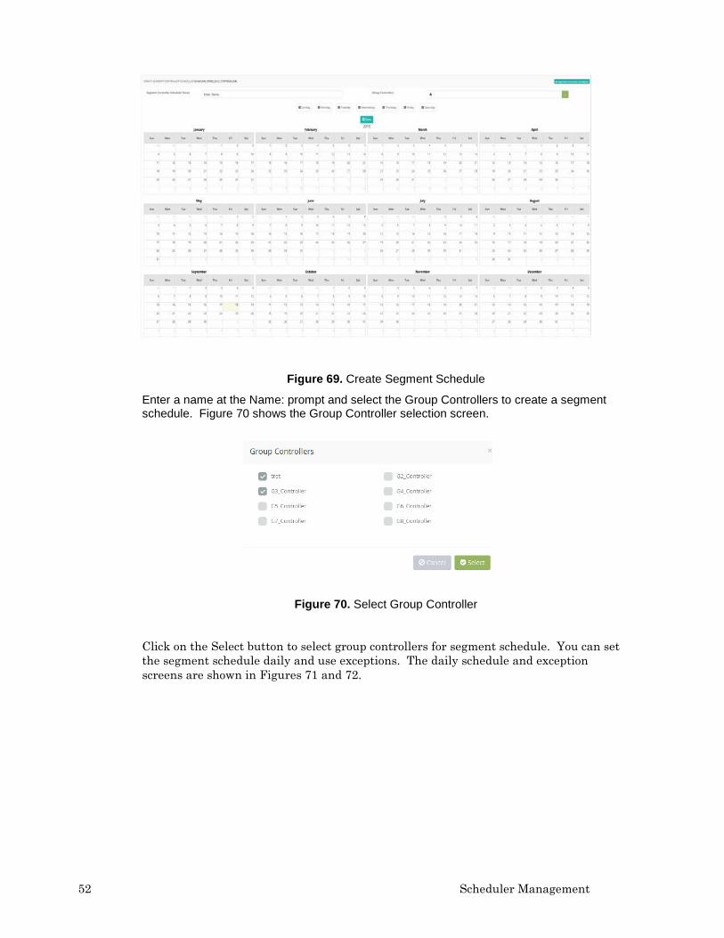
Create Segment Schedule Click the Create Segment Schedule button to set the schedule for a segment of a selected group, as shown in Figure 69.
52 Scheduler Management
Figure 69. Create Segment Schedule
Enter a name at the Name: prompt and select the Group Controllers to create a segment schedule. Figure 70 shows the Group Controller selection screen.
Figure 70. Select Group Controller
Click on the Select button to select group controllers for segment schedule. You can set the segment schedule daily and use exceptions. The daily schedule and exception screens are shown in Figures 71 and 72.
LumInsight Web Portal User’s Guide 53
Figure 71. Daily Schedule
Click in the box at Please Select Scheule Definition. Make your selections and click Save. When selecting the days of the month, you can set exceptions as shown below.
Figure 72. Exception Schedule Definition
The Segment Schedule screens also let you commission and uncommision schedules, as shown in Figures 73 and 74. Click on Apply Commision to activate the commission.
Figure 73. Apply Commision
54 Scheduler Management
Click on Apply Uncommision to uncommission a schedule.
Figure 74. Apply Commision
Update Segment Controller Schedule Click the button to update an already created segment controller schdule, as shown in Figure 75.
Figure 74. Update Segment Controller Schedule
Click on any of the days shown at the top of the screen to make your updates. For example, if you select Sunday, a Daily Schedule Update for Sunday will open. This is shown in Figure 75.
LumInsight Web Portal User’s Guide 55
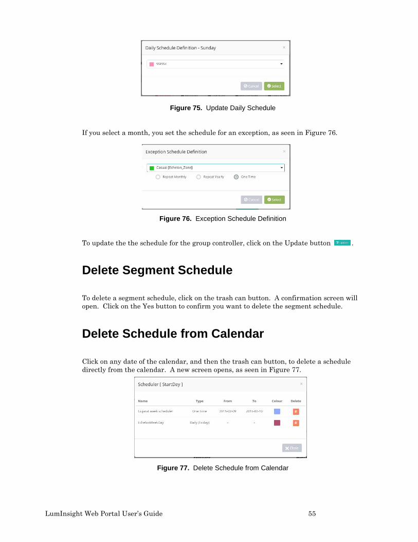
Figure 75. Update Daily Schedule
If you select a month, you set the schedule for an exception, as seen in Figure 76.
Figure 76. Exception Schedule Definition
To update the the schedule for the group controller, click on the Update button .
Delete Segment Schedule
To delete a segment schedule, click on the trash can button. A confirmation screen will open. Click on the Yes button to confirm you want to delete the segment schedule.
Delete Schedule from Calendar
Click on any date of the calendar, and then the trash can button, to delete a schedule directly from the calendar. A new screen opens, as seen in Figure 77.
Figure 77. Delete Schedule from Calendar
56 Scheduler Management
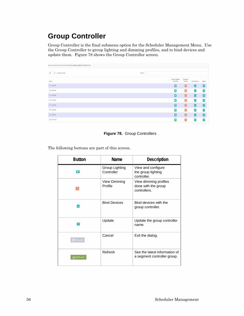
Group Controller Group Controller is the final submenu option for the Scheduler Management Menu. Use the Group Controller to group lighting and dimming profiles, and to bind devices and update them. Figure 78 shows the Group Controller screen.
Figure 78. Group Controllers
The following buttons are part of this screen.
Button Name Description
Group Lighting Controller
View and configure the group lighting controller.
View Dimming Profile
View dimming profiles done with the group controllers.
Bind Devices Bind devices with the group controller.
Update Update the group controller name.
Cancel Exit the dialog.
Refresh See the latest information of a segment controller group.
LumInsight Web Portal User’s Guide 57
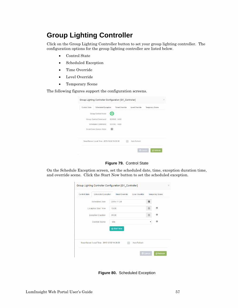
Group Lighting Controller Click on the Group Lighting Controller button to set your group lighting controller. The configuration options for the group lighting controller are listed below.
• Control State
• Scheduled Exception
• Time Override
• Level Override
• Temporary Scene
The following figures support the configuration screens.
Figure 79. Control State
On the Schedule Exception screen, set the scheduled date, time, exception duration time, and override scene. Click the Start Now button to set the scheduled exception.
Figure 80. Scheduled Exception
58 Scheduler Management
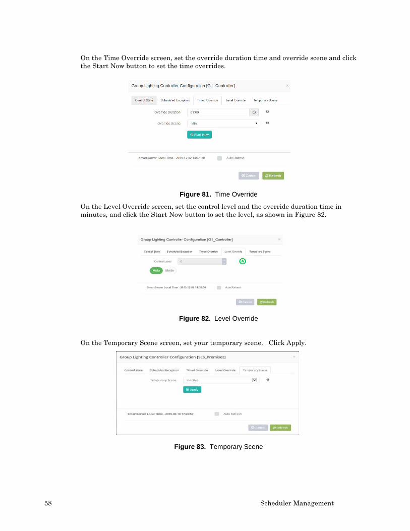
On the Time Override screen, set the override duration time and override scene and click the Start Now button to set the time overrides.
Figure 81. Time Override
On the Level Override screen, set the control level and the override duration time in minutes, and click the Start Now button to set the level, as shown in Figure 82.
Figure 82. Level Override
On the Temporary Scene screen, set your temporary scene. Click Apply.
Figure 83. Temporary Scene
LumInsight Web Portal User’s Guide 59
When the Temporary Scene is set, the Group Override Controller Configuration Scene appears. The status of the temporary scene shows in the window.
Figure 84. Temporary Scene Set Successfully
Dimming Profiles You can also view the Dimming Profiles at this level. Click on the button to view the dimming profiles for a segment group controller, as shown in Figure 85.
Figure 85. Dimming Profiles for Segment Group Controller
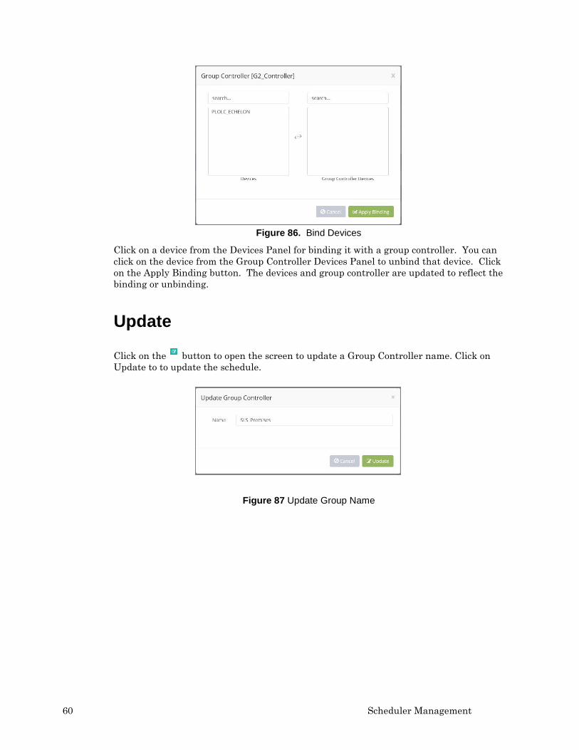
Bind Devices Click on the button to bind devices with a group controller, as shown in Figure 86.
60 Scheduler Management
Figure 86. Bind Devices
Click on a device from the Devices Panel for binding it with a group controller. You can click on the device from the Group Controller Devices Panel to unbind that device. Click on the Apply Binding button. The devices and group controller are updated to reflect the binding or unbinding.
Update
Click on the button to open the screen to update a Group Controller name. Click on Update to to update the schedule.
Figure 87 Update Group Name
LumInsight Web Portal User’s Guide 61
4
Segment Controller Properties
This chapter describes Network Modes, polling of managers, data configuration, the log manager, and TOS binding.
62 Segment Controller Properties
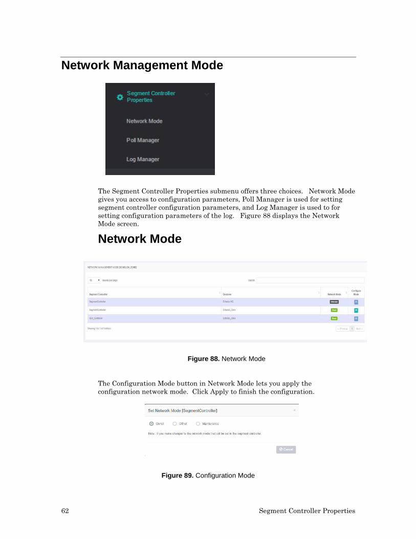
Network Management Mode
The Segment Controller Properties submenu offers three choices. Network Mode gives you access to configuration parameters, Poll Manager is used for setting segment controller configuration parameters, and Log Manager is used to for setting configuration parameters of the log. Figure 88 displays the Network Mode screen.
Network Mode
Figure 88. Network Mode
The Configuration Mode button in Network Mode lets you apply the configuration network mode. Click Apply to finish the configuration.
Figure 89. Configuration Mode
LumInsight Web Portal User’s Guide 63
You can select when network configuration changes are propogated to devices. There are three options available in Netork Mangement Mode.
1. OnNet. This option sends changes immediately to the devices on the network. Select OnNet if you are installing an engineered network, or if you are designing and installing an ad-hoc network at the same time.
2. OffNet. This option keeps changes stored in the network database and sends them to devices on the network when you are in OnNet mode. Select OffNet if you are designing an engineered network.
3. Maintenance. This option is the same as OnNet, except the SmartServer does not send out heartbeat or polling messages. This increases network bandwidth by freeing up the consumption from checking data point heartbeats, sending poll requests, and receving poll message responses. Select Maintenance when you need to increase network bandwidth.
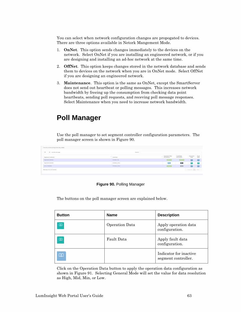
Poll Manager Use the poll manager to set segment controller configuration parameters. The poll manager screen is shown in Figure 90.
Figure 90. Polling Manager
The buttons on the poll manager screen are explained below.
Button Name Description
Operation Data Apply operation data
configuration.
Fault Data Apply fault data
configuration.
Indicator for inactive
segment controller.
Click on the Operation Data button to apply the operation data configuration as shown in Figure 91. Selecting General Mode will set the value for data resolution as High, Mid, Min, or Low.
64 Segment Controller Properties
Figure 91. Operation Data Configuration
If you choose Advance Mode over General Mode, you can set the data resolution manually
Figure 92. Advance Mode Operation Data Configuration
Click on the Fault Data button and the Apply button to apply data configuration.
Log Manager Use the poll manager to set configuration parameters of the log. The log manager is shown in Figure 93.
Figure 93. Log Manager
LumInsight Web Portal User’s Guide 65
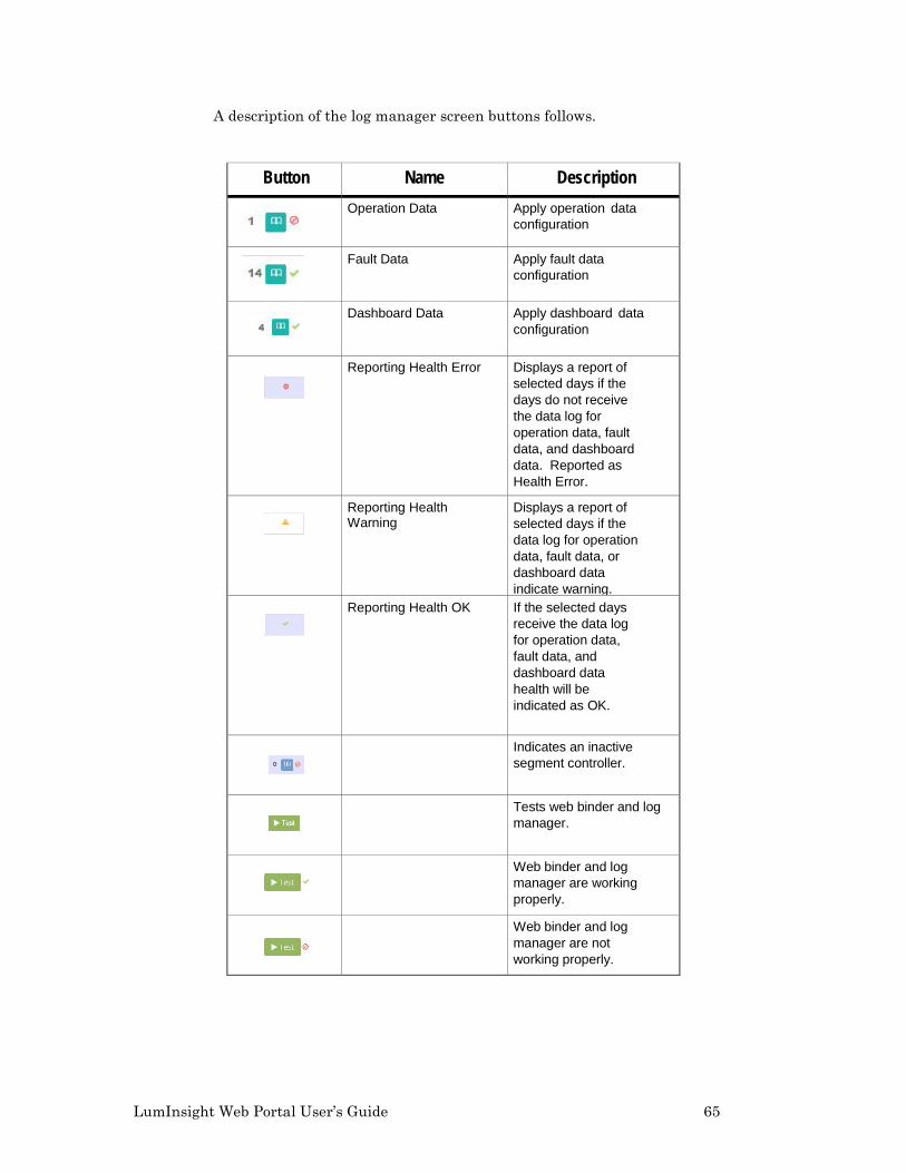
A description of the log manager screen buttons follows.
Button Name Description
Operation Data Apply operation data configuration
Fault Data Apply fault data configuration
Dashboard Data Apply dashboard data configuration
Reporting Health Error Displays a report of
selected days if the days do not receive the data log for operation data, fault data, and dashboard data. Reported as Health Error.
Reporting Health Warning
Displays a report of selected days if the data log for operation data, fault data, or dashboard data indicate warning.
Reporting Health OK If the selected days receive the data log for operation data, fault data, and dashboard data health will be indicated as OK.
Indicates an inactive segment controller.
Tests web binder and log manager.
Web binder and log manager are working properly.
Web binder and log manager are not working properly.
66 Segment Controller Properties
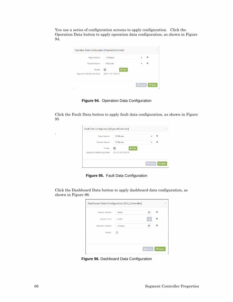
You use a series of configuration screens to apply configuration. Click the Operation Data button to apply operation data configuration, as shown in Figure 94.
Figure 94. Operation Data Configuration
Click the Fault Data button to apply fault data configuration, as shown in Figure 95
.
Figure 95. Fault Data Configuration
Click the Dashboard Data button to apply dashboard data configuration, as shown in Figure 96.
Figure 96. Dashboard Data Configuration
LumInsight Web Portal User’s Guide 67
Traffic Occupancy Sensor (TOS) Binding
The TOS Binding page lets you bind devices with a sensor. You can view the sensor of a selected Geozone (select the sensor from the tree) as well as configure the sensor and device parameters. Figure 90 shows the TOS Binding page.
Figure 97. TOS Binding
The following buttons are used on the TOS Binding page.
Button Name Description
View Geozones Tree
Expand Geozones tree to bind devices with sensor
Bind Device Bind the device
UnBind Device Unbind the device
Bind Device with number of sensors bounded
This shows that the device is bound with 11 sensors.
68 Segment Controller Properties
Button Name Description
Apply Binding Apply the binding for selected devices.
When you right click on a selected motion sensor, you can bind devices as shown in Figure 98.
Figure 98. Bind Devices
Apply Binding to Sensor Use these steps to view a bound sensor list and bind and unbind devices. You can also set the hold time of the sensor. Click on the Apply button to apply the binding. Select the sensor for devices shown in Figure 99. You also set Hold Time here.
LumInsight Web Portal User’s Guide 69
Figure 99. Apply Binding
The buttons on the Apply Binding screen are described below.
Button Name Description
No The device is not bound
Yes The device is bound
Yes - Bound with The device is bound with selected sensor as well as another sensor. One device can bind with a maximum of 11 TOS Sensors.
Appears when the 11 sensors are already bound with the device.
Hover on the chain icon and it will display the list of other sensors bound with that device.
70 Segment Controller Properties
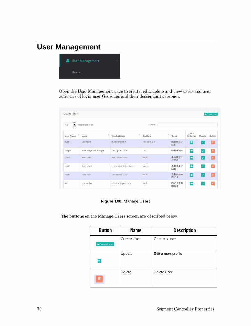
User Management
Open the User Management page to create, edit, delete and view users and user activities of login user Geozones and their descendant geozones.
Figure 100. Manage Users
The buttons on the Manage Users screen are described below.
Button Name Description
Create User Create a user
Update Edit a user profile
Delete Delete user
LumInsight Web Portal User’s Guide 71
User Activity View user activities log
Create User
Click on the Create User button to add a new user. A wizard will open. Fill in all the entry fields. Click the Next button to continue to add information. The next screen will be for User Credentials and then Role Configuration. Use the Previous betton to return to screens you have already viewed. An asterisk in a field (*) indicates that the field is mandatory. Figures 101 and 102 display the User Information and User Credential screens.
Figure 101. User Information
Figure 102. User Credential
The wizard also lets you assign a role to each user. When a user logs in, the display seen is a reflection of the user role. Read through the list and assign what role the user will have and what screens the user can access. Figure 94 shows the role configuration screen.
72 Segment Controller Properties
Figure 103. User Role Configuration
Update User
Once a user profile is created, you can make changes. Click on the edit user button and the User Information screen will open againz.
Figure 104. User Information
Make and save the changes to the user information. You can also make changes in the User Credential screen and on the Role Configuration screen. When you are done making changes, hit the Update button to activate the changes.
In addition to changing a User profile, you can also delete one. Select the user you want to delete on the Manage Users screen and then Click on the trash can button to delete the profile.
LumInsight Web Portal User’s Guide 73
To view user activity, go the Manage Users screen and select a user. Click on the view activity button, shown above, to see current user activity.
LumInsight Web Portal User’s Guide 75
5
Troubleshooting
The troubleshooting menu lets you query the status of a device, test devices, poll statistics, log statistics, access data history, see a report on device lifetime, access failure reports, display faulty devides on a map, and view your energy history.
76 Troubleshooting
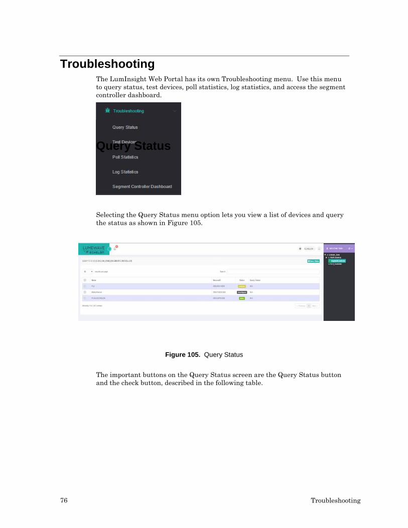
Troubleshooting The LumInsight Web Portal has its own Troubleshooting menu. Use this menu to query status, test devices, poll statistics, log statistics, and access the segment controller dashboard.
Query Status
Selecting the Query Status menu option lets you view a list of devices and query the status as shown in Figure 105.
Figure 105. Query Status
The important buttons on the Query Status screen are the Query Status button and the check button, described in the following table.
LumInsight Web Portal User’s Guide 77
Button Name Description Query Status Query status
(sequentially) of all devices selected.
Status of Individual Device
Query the status of one device.
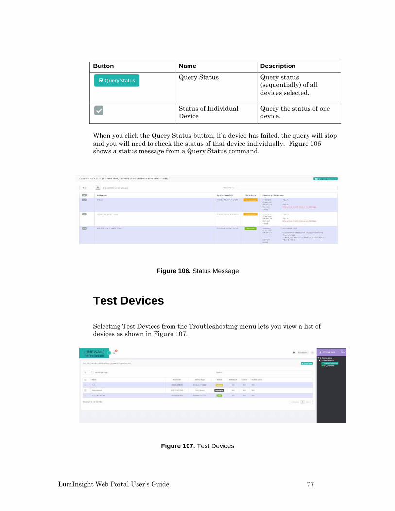
When you click the Query Status button, if a device has failed, the query will stop and you will need to check the status of that device individually. Figure 106 shows a status message from a Query Status command.
Figure 106. Status Message
Test Devices
Selecting Test Devices from the Troubleshooting menu lets you view a list of devices as shown in Figure 107.
Figure 107. Test Devices
78 Troubleshooting
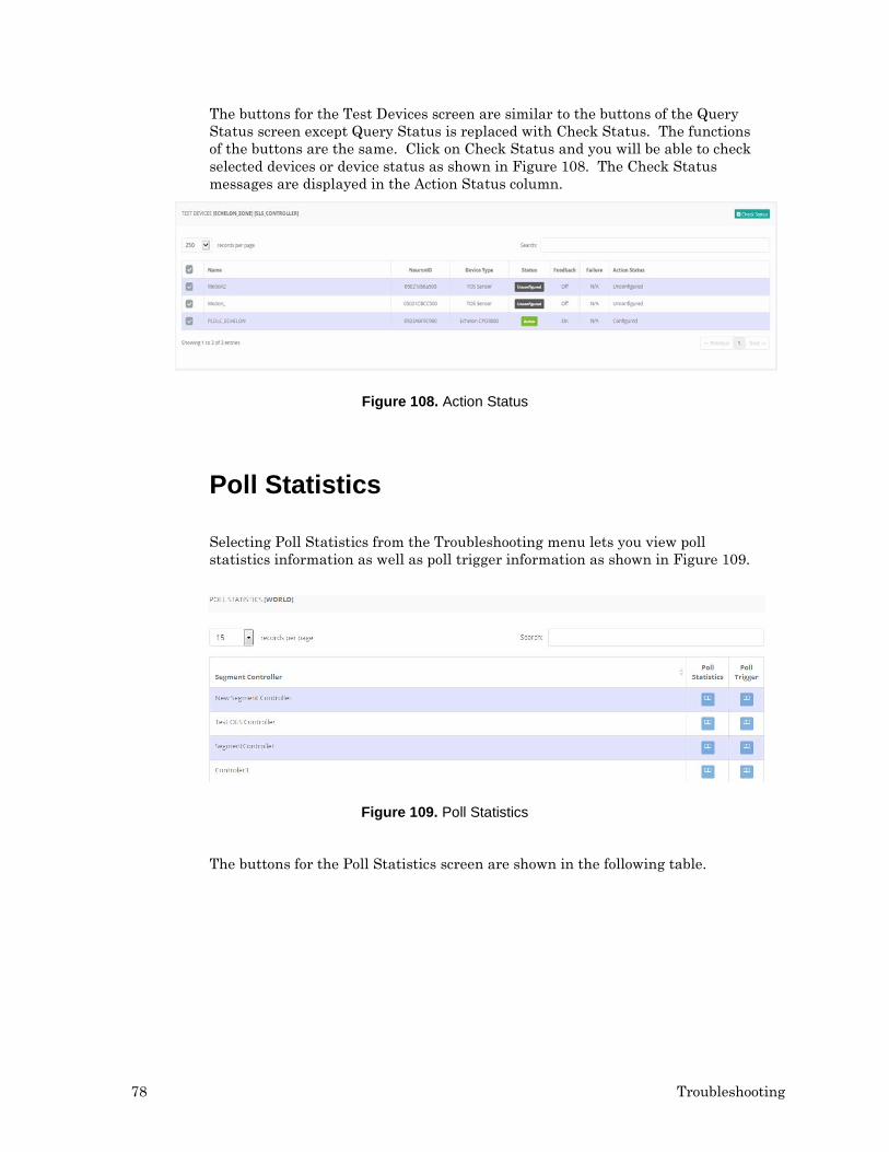
The buttons for the Test Devices screen are similar to the buttons of the Query Status screen except Query Status is replaced with Check Status. The functions of the buttons are the same. Click on Check Status and you will be able to check selected devices or device status as shown in Figure 108. The Check Status messages are displayed in the Action Status column.
Figure 108. Action Status
Poll Statistics
Selecting Poll Statistics from the Troubleshooting menu lets you view poll statistics information as well as poll trigger information as shown in Figure 109.
Figure 109. Poll Statistics
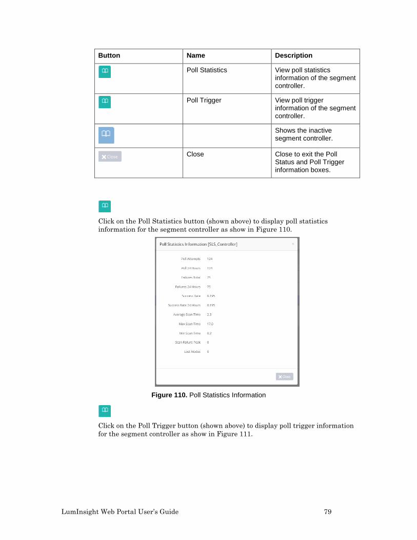
The buttons for the Poll Statistics screen are shown in the following table.
LumInsight Web Portal User’s Guide 79
Button Name Description
Poll Statistics View poll statistics information of the segment controller.
Poll Trigger View poll trigger information of the segment controller.
Shows the inactive segment controller.
Close Close to exit the Poll Status and Poll Trigger information boxes.
Click on the Poll Statistics button (shown above) to display poll statistics information for the segment controller as show in Figure 110.
Figure 110. Poll Statistics Information
Click on the Poll Trigger button (shown above) to display poll trigger information for the segment controller as show in Figure 111.
80 Troubleshooting
.
Figure 111. Poll Trigger Information
Log Statistics
The Log Statistics page is used to view operation statistics, fault statistics, and dashboard statistic information as shown in Figure 112.
Figure 112. Log Statistics
Buttons for the Log Statistics page are explained in the following table.
LumInsight Web Portal User’s Guide 81
Button Name Description
Operation Statistics Display the operation data information.
Fault Statistics Apply the fault data configuration.
Dashboard Statistics Apply the dashboard data configuration.
Shows the inactive segment controller.
Click on the Operation Statistics button (shown above) to display the operation statistics as shown in Figure 113.
Figure 113. Operation Statistics
Click on the Fault Statistics button (shown above) to display the fault data information as shown in Figure 114.
Figure 114. Fault Statistics
82 Troubleshooting
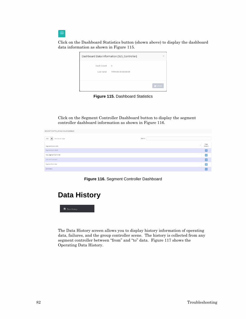
Click on the Dashboard Statistics button (shown above) to display the dashboard data information as shown in Figure 115.
Figure 115. Dashboard Statistics
Click on the Segment Controller Dashboard button to display the segment controller dashboard information as shown in Figure 116.
Figure 116. Segment Controller Dashboard
Data History
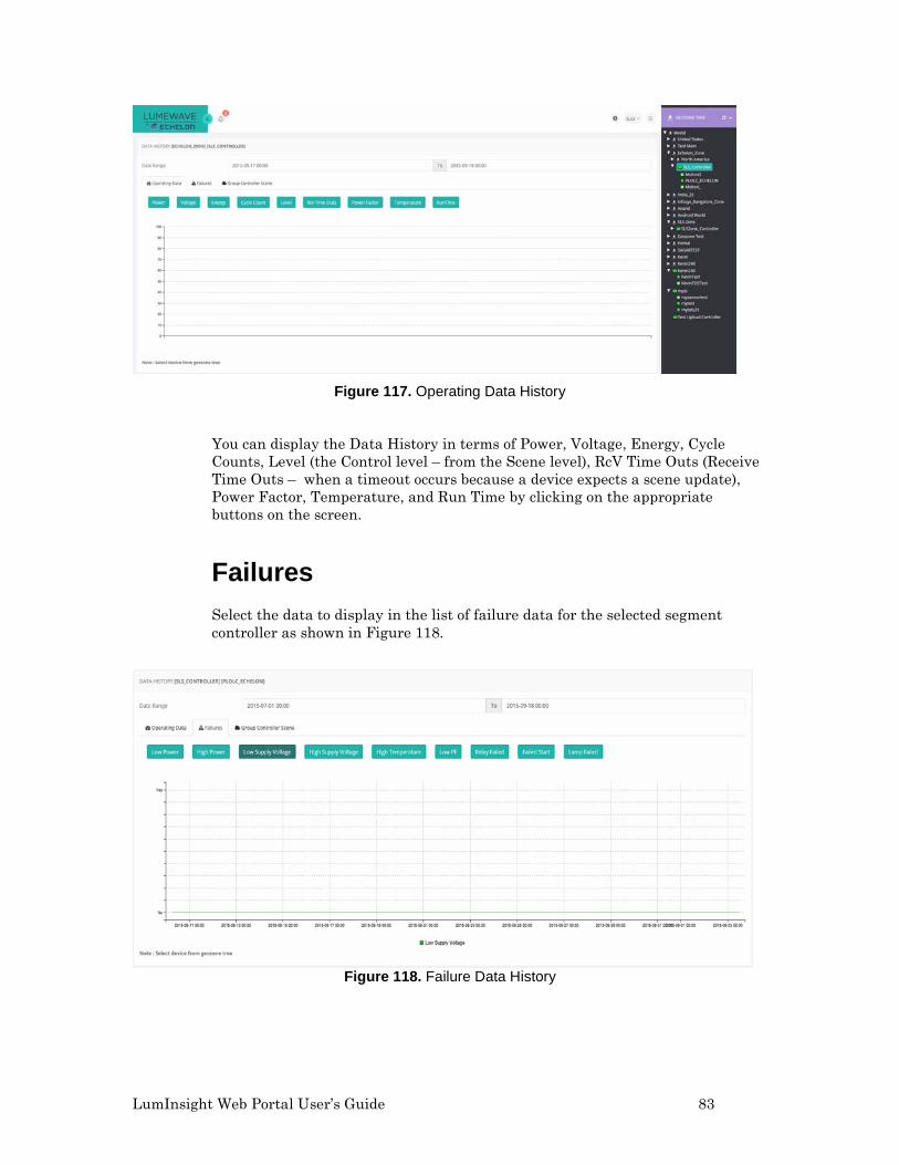
The Data History screen allows you to display history information of operating data, failures, and the group controller scene. The history is collected from any segment controller between “from” and “to” data. Figure 117 shows the Operating Data History.
LumInsight Web Portal User’s Guide 83
Figure 117. Operating Data History
You can display the Data History in terms of Power, Voltage, Energy, Cycle Counts, Level (the Control level – from the Scene level), RcV Time Outs (Receive Time Outs – when a timeout occurs because a device expects a scene update), Power Factor, Temperature, and Run Time by clicking on the appropriate buttons on the screen.
Failures Select the data to display in the list of failure data for the selected segment controller as shown in Figure 118.
Figure 118. Failure Data History
84 Troubleshooting
Data Failure is displayed in terms of Low Power, High Power, Low Supply Voltage, High Supply Voltage, Low Power Factor, Relay Failed, Failed Start, and Lamp Failed. Click the button on the Data History screen to see the selected failure.
Group Controller Screen
Select the Group Controller Screen to display the scene of a selected segment controller as shown in Figure 119.
Figure 119. Group Controller Screen
Reports Use the Report Menu to see reports on Device Lifetime, Failure Analysis, Failure Tracking, and Energy History.
LumInsight Web Portal User’s Guide 85
Display the Device Lifetime Pie Chart for a Selected Geozone
Click on the button, shown above, to display the device lifetime (e.g., lamp lifetime) pie chart for a selected Geozone. It displays the Geozone tree and you select the Geozone from the tree. The device lifetime analysis pie chart for the root Geozone is automatically displayed, as shown in Figure 109.
Figure 120. Pie Chart for a Select Geozone
Each slice of the pie chart represents the devices whose percentage of expected lifetime is comprised between the pie slice limits (e.g., between 95% and 100%). The percentage of expected lifetime is measured by comparing the number of running hours measured by the OLC that drives the device to the expected lamp lifetime.
• Get the number of devices and the percentage of devise in each slice byhovering your pointer over the pie slice.
• Display the list of devices included in a pie slice by clicking the slice.
Failure Analysis
Select Failure Analysis from the Reports menu. It opens a page that provides end-users with the number an percentage of devices and their failures per Geozone in which failure devices were detected. A failure analysis screen is shown in Figure 121.
86 Troubleshooting
Figure 121. Failure Analysis
Click on the Export button at the top of the screen to export the content of the displayed failure analysis into a .CVS file.
Click on the Refresh button (shown above) to reload and refresh the report.
Display the Aggregated Failure Report for a Selected Geozone
Select Failure Analysis from the Reports menu. When loading the Failure Analysis, the display automatically displays the aggregrated report for the login user Geozone and any descendant Geozones.
Select the Geozone from the Geozone Tree by clicking on the button shown above. It will produce an aggregated failure report for the selected Geozone. The aggregated failure report is only displayed for a Geozone that contains failed devices. Figure 122 shows a report with failures.
Figure 122. Aggregated Failures Report
LumInsight Web Portal User’s Guide 87
Click on the Export button in the upper right-hand of the screen to export the content of the aggregated failure report for a particular Geozone into a .CVS file.
Click on the Refresh button, shown above, to reload and refresh the report.
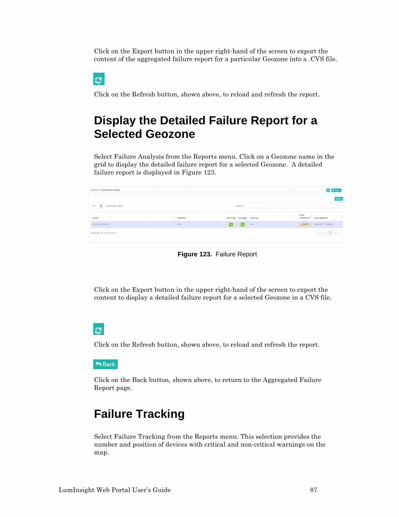
Display the Detailed Failure Report for a Selected Geozone
Select Failure Analysis from the Reports menu. Click on a Geozone name in the grid to display the detailed failure report for a selected Geozone. A detailed failure report is displayed in Figure 123.
Figure 123. Failure Report
Click on the Export button in the upper right-hand of the screen to export the content to display a detailed failure report for a selected Geozone in a CVS file.
Click on the Refresh button, shown above, to reload and refresh the report.
Click on the Back button, shown above, to return to the Aggregated Failure Report page.
Failure Tracking
Select Failure Tracking from the Reports menu. This selection provides the number and position of devices with critical and non-critical warnings on the map.
88 Troubleshooting
Aggregated Number of Failures per Geozone
Click on the button shown above and select a Geozone from the Geozone Tree. This will display the aggregated number of failures per Geozone.
Display all Geozones. For any sub-Geozone that contains devices with failures, the number of failures in each sub-Geozone is displayed in a bubble. The bubble is red if there is a critical failure. The bubble is orange if here are only non-critical failures. If no failure has been detected on your devices, the bubble is green. A map with critical failure (red) is shown in Figure 124.
Figure 124. Aggregated Number of Failures per Geozone
Display Faulty Devices on a Map
To display faulty devices on the map, click on a Geozone that contains devices. The devises will display in the following colors.
Color Description
Green No failure detected on this device.
Red Device has critical failure, such as an outage.
Orange Device has non-critical failure, such as a warning.
LumInsight Web Portal User’s Guide 89
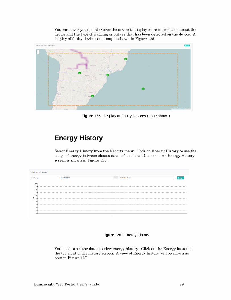
You can hover your pointer over the device to display more information about the device and the type of warning or outage that has been detected on the device. A display of faulty devices on a map is shown in Figure 125.
Figure 125. Display of Faulty Devices (none shown)
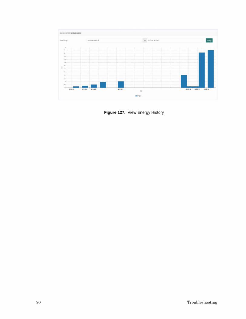
Energy History
Select Energy History from the Reports menu. Click on Energy History to see the usage of energy between chosen dates of a selected Geozone. An Energy History screen is shown in Figure 126.
Figure 126. Energy History
You need to set the dates to view energy history. Click on the Energy button at the top right of the history screen. A view of Energy history will be shown as seen in Figure 127.