Abstract — The paper is dealing with the principles for modeling and simulating by 3D simulators of the well-known Lüneburg lenses used as communication antenna devices. The models of spherical, semi-spherical and cylindrical multi- layer dielectric lenses are discussed. The results show the effectiveness of the proposed simulation procedures for investigation of the focusing effects and antenna parameters of these large-scale beam-forming devices. Keywords — antennas, dielectric antennas, electromagnetic 3D simulators, focusing, lens antennas. I. INTRODUCTION AND BASIC MODEL HE Lüneburg lens is historically connected with the possibilities of transforming the plane wave into a point-like spherical wave or vice versa [1]. Considered as an antenna, if the Lüneburg lens is illuminated by a plane wave from a remote source – satellite or HAP (High- Altitude Platform) antenna, the wave front will be focused into a small receiving horn/patch (or v. v.), acting like an antenna array with relatively high gain, small main-lobe beam-width and low-level side lobes. Nowadays there is a great interest in such type of antennas for applications in the modern mobile communications [2], radioastronomy [3], etc. Moreover, the Lüneburg lenses at the moment are considered as the simplest and the cheapest passive steerable antennas for communication purposes [4]. The big Lüneburg lenses have an advantage related to the phase antenna arrays, because they can simultaneously collect signals from all directions (multi-beam option). Other serious advantage is the broadband operation. These lens antennas can be manufactured with inexpensive dielectric materials and without any active elements. Their main disadvantages are the large size, the relatively big dielectric loss and the fabrication complexity. The focusing action of the classical Lüneburg lens is based on the gradient distribution of the refraction index n(r) or the relative dielectric constant ε r into a sphere with radius R. The fundamental expression is: The authors thank to the Scientific Research Found of the University of Sofia “St. Kliment Ohridski” for the partial financial support. Slavi Baev is an antenna engineer in RaySat BG; a PhD student in the Technical University, Sofia (e-mail: [email protected]). Svilen Gechev is a MS student in the Faculty of Physics; Boyan Hadjistamov is a PhD student in the Faculty of Physics. Dr. Plamen I. Dankov is an Assoc. Prof. in the Faculty of Physics, University of Sofia; 5, J. Bourchier blvd, 1164-Sofia, Bulgaria (e-mail: [email protected]) () 2 ) / ( 2 R r r n − = or () 2 ) / ( 2 R r r r − = ε (1) According to (1) the dielectric constant near to the outer sphere surface should be ε r = 1 (air), while in the centre of the sphere ε r = 2 (Fig. 1). This distribution is not easy to be exactly realized. The practical realization utilizes step- recovery distribution in N layers with regular or irregular width (or the radius of the corresponding coaxial sphere). Therefore, the lens focusing action depends first of all on the ability to construct the necessary distribution of the dielectric constant in the sphere volume. We can classify two main methods for construction of materials with accurately assigned values of the dielectric constant: i) by dielectric mixtures [4] and ii) by mechanically inserted air- filled holes into plane slices of homogeneous plastic mate- rial with relatively small dielectric constant (2.1-2.5) [5]. The simplest design of Lüneburg lens with appropriate dimensions for a given frequency range is based on the physical optics [6] and the well-known ray-tracing model. The diameter of the spherical lens should be chosen to be more than 10λ (λ – the wavelength in the considered struc- ture at the operation frequency). This fact shows that the Lüneburg lens is an electrically big structure and, therefore, it is very difficult to be precisely simulated by electromagnetic FEM- or FDTD-based simulators. For example, the L-band lenses are with diameter ~5-10 m, Ku-band lenses – 20-25-cm, 30-40-GHz lenses – 10-15 cm, 300-GHz lenses – 20 mm. In this paper we present our experience to simulate big Lüneburg lenses by 3D electro- magnetic simulators (e.g. Ansoft® HFSS-8 and 11 [7]). We investigate the focusing effect in different lens structures with a different number of layers and shapes; consider the parasitic resonance effects and the influence of the dielectric anisotropy. Finally, the main antenna parameters: gain and radiation patterns, are determined by simulations. Modeling and Simulations of Lüneburg Lens Antennas for Communication Purposes Slavi R. Baev, Student Member, IEEE, Svilen M. Gechev, Student Member, IEEE, Boyan N. Hadjistamov, and Plamen I. Dankov, Member, IEEE T Fig. 1. The exact distribution of the dielectric constant into the Lüneburg lens (black line) and its step-recovery model (red) 2R 488
Transcript
Abstract — The paper is dealing with the principles for
modeling and simulating by 3D simulators of the well-known Lüneburg lenses used as communication antenna devices. The models of spherical, semi-spherical and cylindrical multi-layer dielectric lenses are discussed. The results show the effectiveness of the proposed simulation procedures for investigation of the focusing effects and antenna parameters of these large-scale beam-forming devices.
HE Lüneburg lens is historically connected with the possibilities of transforming the plane wave into a
point-like spherical wave or vice versa [1]. Considered as an antenna, if the Lüneburg lens is illuminated by a plane wave from a remote source – satellite or HAP (High-Altitude Platform) antenna, the wave front will be focused into a small receiving horn/patch (or v. v.), acting like an antenna array with relatively high gain, small main-lobe beam-width and low-level side lobes. Nowadays there is a great interest in such type of antennas for applications in the modern mobile communications [2], radioastronomy [3], etc. Moreover, the Lüneburg lenses at the moment are considered as the simplest and the cheapest passive steerable antennas for communication purposes [4]. The big Lüneburg lenses have an advantage related to the phase antenna arrays, because they can simultaneously collect signals from all directions (multi-beam option). Other serious advantage is the broadband operation. These lens antennas can be manufactured with inexpensive dielectric materials and without any active elements. Their main disadvantages are the large size, the relatively big dielectric loss and the fabrication complexity.
The focusing action of the classical Lüneburg lens is based on the gradient distribution of the refraction index n(r) or the relative dielectric constant εr into a sphere with radius R. The fundamental expression is:
The authors thank to the Scientific Research Found of the University of Sofia “St. Kliment Ohridski” for the partial financial support.
Slavi Baev is an antenna engineer in RaySat BG; a PhD student in the Technical University, Sofia (e-mail: [email protected]). Svilen Gechev is a MS student in the Faculty of Physics; Boyan Hadjistamov is a PhD student in the Faculty of Physics. Dr. Plamen I. Dankov is an Assoc. Prof. in the Faculty of Physics, University of Sofia; 5, J. Bourchier blvd, 1164-Sofia, Bulgaria (e-mail: [email protected])
( ) 2)/(2 Rrrn −= or ( ) 2)/(2 Rrrr −=ε (1)
According to (1) the dielectric constant near to the outer sphere surface should be εr = 1 (air), while in the centre of the sphere εr = 2 (Fig. 1). This distribution is not easy to be exactly realized. The practical realization utilizes step-recovery distribution in N layers with regular or irregular width (or the radius of the corresponding coaxial sphere). Therefore, the lens focusing action depends first of all on the ability to construct the necessary distribution of the dielectric constant in the sphere volume. We can classify two main methods for construction of materials with accurately assigned values of the dielectric constant: i) by dielectric mixtures [4] and ii) by mechanically inserted air-filled holes into plane slices of homogeneous plastic mate-rial with relatively small dielectric constant (2.1-2.5) [5].
The simplest design of Lüneburg lens with appropriate dimensions for a given frequency range is based on the physical optics [6] and the well-known ray-tracing model. The diameter of the spherical lens should be chosen to be more than 10λ (λ – the wavelength in the considered struc-ture at the operation frequency). This fact shows that the Lüneburg lens is an electrically big structure and, therefore, it is very difficult to be precisely simulated by electromagnetic FEM- or FDTD-based simulators. For example, the L-band lenses are with diameter ~5-10 m, Ku-band lenses – 20-25-cm, 30-40-GHz lenses – 10-15 cm, 300-GHz lenses – 20 mm. In this paper we present our experience to simulate big Lüneburg lenses by 3D electro-magnetic simulators (e.g. Ansoft® HFSS-8 and 11 [7]). We investigate the focusing effect in different lens structures with a different number of layers and shapes; consider the parasitic resonance effects and the influence of the dielectric anisotropy. Finally, the main antenna parameters: gain and radiation patterns, are determined by simulations.
Modeling and Simulations of Lüneburg Lens Antennas for Communication Purposes
Slavi R. Baev, Student Member, IEEE, Svilen M. Gechev, Student Member, IEEE, Boyan N. Hadjistamov, and Plamen I. Dankov, Member, IEEE
T
Fig. 1. The exact distribution of the dielectric constant into the Lüneburg lens (black line) and its step-recovery model (red)
2R
488
II. INVESTIGATION OF THE FOCUSING EFFECTS
A. Modeling of Lüneburg lenses by 3D simulators
The classical 3D model should consist of the multi-layer focusing lens, the small-aperture illuminator (horn, planar patch, etc.) and a “radiation box”, which should ensure enough “room” for calculating the scattering fields around the antenna (see Fig. 12 in §IV). The last circumstance is very important for successful simulations, but the big dimensions of the structure do not allow fast and accurate preliminary design of the lenses. Therefore, we propose a different 3D model for effective Lüneburg lens design: lens body, rectangular (2R×2R) planar source of plane wave, illuminating the whole lens and a PML (Perfectly-Matched-Layer) box to put the structure in – Fig. 2. Calculating the E-field distribution, we can determine the places, where the plane wave will be focused – the primary and high-order focuses outside the dielectric sphere.
The usefulness of the proposed model for simulation of
the focusing effect of the Lüneburg lens is demonstrated in Fig. 3. We can observe and compare the dimensions and the E-field strength of the focusing spots for lenses with different number of layers. Thereby, the optimal number of layers N can be preliminary determined, depending on the application of the antenna (usually N ≥ 5-6).
Finally, a very effective way to speed up the lens simula-tion keeping the accuracy is a symmetrical splitting of the sphere – see Fig.4. A quarter-sphere slice has turned out to be the most optimal lens model. Depending on the E-field direction of the plane wave, the flat surfaces of the slice should be boundaries with E-field (for E perpendicular to surface) or H-field symmetry (for E parallel to surface).
B. Resonance effects at low frequencies
The Lüneburg lens antenna is in principle a broadband device. In fact, the frequency bandwidth is restricted from below, due to the influence of the parasitic low-frequency resonances on the focusing effect. The model proposed here for simulation allows to easily obtain the resonance frequencies of the first low-order resonances of the sphere (see Fig. 5). Our investigations show that the practical low-frequency limit of the Lüneburg lens antenna for well enough focusing is fL ~ (2-3) f1, where f1 is the lowest-order resonance frequency of the dielectric sphere.
C. Frequency dependence of the focusing effect
Now we can step in the next stage of the lens design – to investigate the focusing effect versus the frequency. We concentrate our attention to determine the position of the first focus outside the sphere; the high-order focuses are not interesting for antenna applications. We apply every-where the simplest quarter-split model (Fig. 4c). Realistic simulations are possible up to f ~ (10-15) f1; above ~15f1 the computational platform used should have enough RAM memory (e.g. > 4 GB). Fig. 6 presents the frequency beha-vior of the focusing effect in 200-mm Lüneburg lens. We can trace the evolution of the position of the focuses (the spots with E-field maximums) with the decreasing of the wavelength. The first outside focus is well defined at high frequencies. The number of inside focuses (into the sphere) increases with the frequency. Contrariwise, no outside fo-cuses exist at the resonances and destroying of the focusing effect is detected near to the low-frequency resonances. Thus, the frequency bandwidth of the Lüneburg lens can be estimated, for example, between fL ~ 5f1 up to very high frequencies, when separate layers might act like single resonators. At very high frequency we observe additional outside focuses near to the primary focus, but they could be minimized by optimization of the multilayer distribution
First focus
High-order focuses
Plane wave source
PML box
Lüneburg lens
Fig. 2. Typical HFSS simulation, which clearly illustrates the focusing effect of a plane wave into a primary focus near to the sphere surface and the existence of high-order focuses
(linear-plot distribution of the E-field magnitude)
Once splitted sphere
Twice splitted sphere
(“Orange” slice)
Full sphere in a small PML box
Fig. 4. Illustration of the splitting of the simulated Lüneburg lens: a) full-sphere structure with dimensions 230x230x230 mm (the
high-order focuses are not considered); c) once splitted structure (1/2 from the whole volume); d) twice splitted structure (1/4 from
the whole volume); no more symmetrical splitting is possible!
a b c
Fig. 5. Resonance performances of 10-layer Lüneburg lens with R = 100 mm: a) vector E-field distribution at the lowest-order
resonance at 658 MHz; b) focusing effect does not exist
a b
Fig. 3. Focusing abilities of 200-mm Lüneburg lens with different number N of layers (f = 3.5 GHz): the focussing effect
becomes worse, when N ≤ 2-4 (log scale)
10 layers 5 layers 3 layers 2 layers
489
D. Optimization of the multi-layer distribution
Fig. 7 demonstrates again the focusing effect by spheres with different number of layers, but at a relatively high frequency (f = 10 GHz for a sphere with R =100 mm). Now the focusing effect is more clearly expressed and we can observe new effects in dependence of the number of layers used in the model (N = 10, 5, 4, 3, 2). If the lens has N = 10 regular layers, the primary focus outside the sphere volume is close to the sphere surface at a distance a ~ 5 mm. In the case of N = 5 this distance becomes bigger, a ~ 7 mm and for N = 4, a ~ 9 mm (i.e. the primary focus spot moves away from the surface and the focusing effect becomes weaker). Further, in the case of N = 3, 2 the considered first focus outside the lens volume is already not well defined (the E-field level is weaker). Therefore, we can conclude, that N = 5-10 of the layers number are optimal enough to construct a well-focusing Lüneburg lens antenna for communication purposes.
We also present simulations of a 200-mm Lüneburg lens with 8 irregular-in-thickness layers – see Fig. 8a. The focusing effect becomes excellent even for smaller number of irregular layers (for example 4, not shown). An interesting approximation is the forming of the sphere as several cylinders (here 8) with different heights, one over the other – Fig. 8b. Each of these cylinders contains a number of coaxial cylinders with a decreasing dielectric constant (see [5]), controlled by a different number of air-filled holes.
E. Effect of the anisotropy of the dielectric layers
The last problem, which we have to check, is the influence of the possible anisotropy of the dielectric constant over the focusing effect. We find out that anisotropy is important, if it leads to a change of the needed dielectric-constant distribution of the sphere lens. Thus, layers with big anisotropy may destroy the focusing action of the sphere as a Lüneburg lens – Fig. 9c.
III. LÜNEBURG LENSES OF DIFFERENT SHAPES
A. Conventional spherical lens
The spherical Lüneburg lens is a classical antenna element, which focus is at the opposite end of the incoming wave. Up to now, we have investigated only this type of lenses. However, other more effective types of lenses can be utilized for communication purposes.
B. Semi-spherical lens
One of the most suitable antennas for satellite communi-cations is the semi-spherical Lüneburg lens with a flat, metalized bottom surface. In this case the primary focus is placed at 90o according to the direction of the incoming from the satellite signal [2]. This lens ensures more reliable mechanical constructions for steerable satellite or HAP antennas. Fig. 10 shows the focusing effect in a simulated semi-spherical Lüneburg lens with 5 irregular layers. Now we simulate a half part of the semi-sphere, but the simula-
a b
Fig. 8. Optimized modeling of spherical lens: a) with coaxial irregular layers; b) with cylindrical slices (log scale)
Fig. 6. Frequency dependence of the focusing effect in 10-layer high-frequency Lüneburg lens with diameter 200 mm (log scale)
2.45 GHz 3.5 GHz 5.8 GHz 8 GHz 10 GHz
Fig. 7. Demonstration of the focusing abilities of 200-mm Lüneburg lens with different number of layers at higher frequency f = 10 GHz, simulating 1/4-part of the whole structure (the scale is linear)
10 layers 5 layers 4 layers 3 layers 2 layers
Fig. 9. Demonstration of the de-focusing effect in Lüneburg lens with the anisotropy of the dielectric constant of the layers: a) isotropic case; b) case of longitudinal anisotropy; c) case of
transversal anisotropy (log scale)
a b c
a b
Fig. 10. Semi-spherical lens with metal screen, which primary focus is in perpendicular direction to the incoming signal
Normal polarization
Parallel polarization
Metal screen Metal screen
Fig. 11. Cylindrical Lüneburg lens, which gives a tape-like focus
a b
490
tions are less efficient due to reflections. We observe good focusing effect in the both directions of polarization – normal (E field of the plane wave is perpendicular to the metal screen) and parallel (E field is parallel to the metal screen). This is very important for the realization of dual-polarization satellite antennas.
C. Cylindrical lens
An interesting and fully applicable cylindrical Lüneburg lens is shown in Fig. 11. It is similar to the semi-spherical lens, but it is constructed by irregular coaxial cylindrical layers. The specific peculiarity of this lens is the shape of the focus spot as a long thin tape along to the cylinder axis.
IV. SIMULATION OF THE ANTENNA PARAMETERS
The presented preliminary design of the Lüneburg lens, based on the focusing effect, can give the optimal value of the sphere diameter for the chosen frequency range, the lens shape and focus position, the optimized distribution of the layers, etc., but can not give the antenna parameters – radiation patterns, gain, efficiency, etc. Besides, the interaction between the illuminating horn and the whole antenna is not known.
Therefore, we can finish the design procedure with simulations of the realistic structure: the whole lens and the illuminating source. The antenna source – open-end cylin-drical waveguide, horn or planar patch, might be separately optimized for the frequency range of interest. In fact, the matching of the Lüneburg lens antenna, the restrictions in the operation bandwidth and even the cross-polarization level depend mainly on the horn properties. We use in this paper a simple cylindrical open-end waveguide with a nar-row frequency band around 10 GHz, set at distance 5 mm to the lens surface with elevation angle 45O. The aim is to construct a reasonable 3D model of the whole antenna: semi-spherical 8-layer lens and a simple source – Fig. 12a.
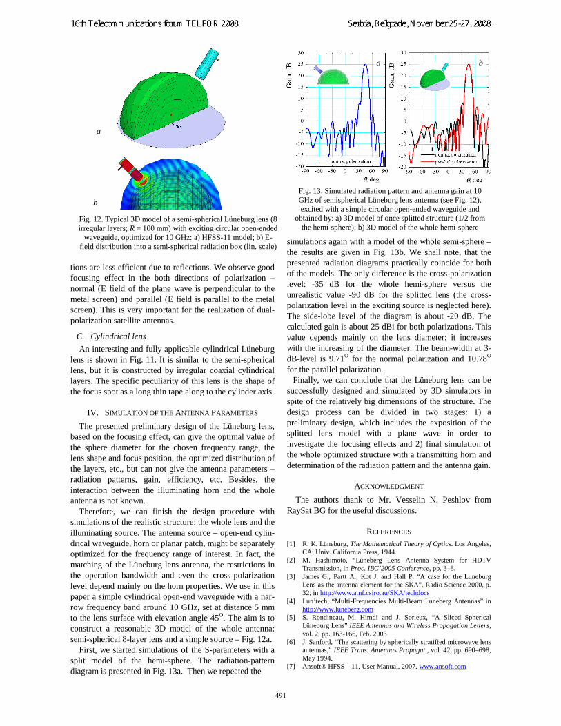
First, we started simulations of the S-parameters with a split model of the hemi-sphere. The radiation-pattern diagram is presented in Fig. 13a. Then we repeated the
simulations again with a model of the whole semi-sphere – the results are given in Fig. 13b. We shall note, that the presented radiation diagrams practically coincide for both of the models. The only difference is the cross-polarization level: -35 dB for the whole hemi-sphere versus the unrealistic value -90 dB for the splitted lens (the cross-polarization level in the exciting source is neglected here). The side-lobe level of the diagram is about -20 dB. The calculated gain is about 25 dBi for both polarizations. This value depends mainly on the lens diameter; it increases with the increasing of the diameter. The beam-width at 3-dB-level is 9.71O for the normal polarization and 10.78O for the parallel polarization.
Finally, we can conclude that the Lüneburg lens can be successfully designed and simulated by 3D simulators in spite of the relatively big dimensions of the structure. The design process can be divided in two stages: 1) a preliminary design, which includes the exposition of the splitted lens model with a plane wave in order to investigate the focusing effects and 2) final simulation of the whole optimized structure with a transmitting horn and determination of the radiation pattern and the antenna gain.
ACKNOWLEDGMENT
The authors thank to Mr. Vesselin N. Peshlov from RaySat BG for the useful discussions.
REFERENCES [1] R. K. Lüneburg, The Mathematical Theory of Optics. Los Angeles,
CA: Univ. California Press, 1944. [2] M. Hashimoto, “Luneberg Lens Antenna System for HDTV
Transmission, in Proc. IBC’2005 Conference, pp. 3–8. [3] James G., Partt A., Kot J. and Hall P. “A case for the Luneburg
Lens as the antenna element for the SKA”, Radio Science 2000, p. 32, in http://www.atnf.csiro.au/SKA/techdocs
[4] Lun’tech, “Multi-Frequencies Multi-Beam Luneberg Antennas” in http://www.luneberg.com
[5] S. Rondineau, M. Himdi and J. Sorieux, “A Sliced Spherical Lüneburg Lens” IEEE Antennas and Wireless Propagation Letters, vol. 2, pp. 163-166, Feb. 2003
[6] J. Sanford, “The scattering by spherically stratified microwave lens antennas,” IEEE Trans. Antennas Propagat., vol. 42, pp. 690–698, May 1994.
[7] Ansoft® HFSS – 11, User Manual, 2007, www.ansoft.com
Fig. 12. Typical 3D model of a semi-spherical Lüneburg lens (8 irregular layers; R = 100 mm) with exciting circular open-ended
waveguide, optimized for 10 GHz: a) HFSS-11 model; b) E-field distribution into a semi-spherical radiation box (lin. scale)
a
b
Fig. 13. Simulated radiation pattern and antenna gain at 10 GHz of semispherical Lüneburg lens antenna (see Fig. 12), excited with a simple circular open-ended waveguide and
obtained by: a) 3D model of once splitted structure (1/2 from the hemi-sphere); b) 3D model of the whole hemi-sphere


![B-K LIGHTING1].pdf · Lens Type 9 - Clear (Standard) 10 - Spread Lens* 12 - Soft Focus Lens* 13 - Rectilinear Lens* Shielding 11 - Honeycomb Baffle* *Accommodates up to 2 Lens/Shielding](https://static.documents.pub/doc/80x56/5ca1866288c993eb5d8c7029/b-k-1pdf-lens-type-9-clear-standard-10-spread-lens-12-soft-focus.jpg)


