Page 1
Yiping [email protected]
LUSI DOE Review July 23, 2007Breakout Presentations 1
LUSI Experiment NeedsYiping Feng
LUSI Experiment NeedsYiping Feng
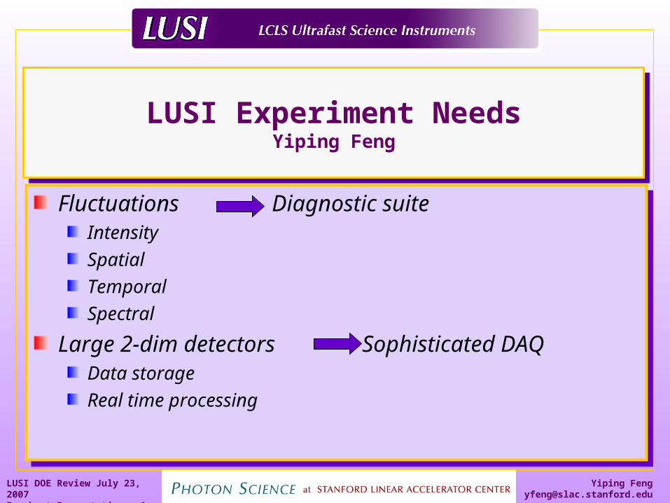
Fluctuations Diagnostic suiteIntensitySpatialTemporalSpectral
Large 2-dim detectors Sophisticated DAQData storageReal time processing
Fluctuations Diagnostic suiteIntensitySpatialTemporalSpectral
Large 2-dim detectors Sophisticated DAQData storageReal time processing
Page 2
Yiping [email protected]
LUSI DOE Review July 23, 2007Breakout Presentations 2
Electron Beam CharacteristicsElectron Beam Characteristics
X-ray Free-Electron Laser (FEL) is fundamentally different from storage-ring based synchrotron sources. For the LCLS
photo-injection at 120 Hz at LCLSEach macro electron bunch is different at origination
Different timing, length, density
After passing through the Linac including acceleration and compression
Added difference in timing, length, densityAdditional difference in energy, orbit
Orbit correction less effective due to low repetition rate in contrast to synchrotron sources (revolution frequency at APS = 272 kHz)
Page 3
Yiping [email protected]
LUSI DOE Review July 23, 2007Breakout Presentations 3
X-ray Beam CharacteristicsX-ray Beam Characteristics
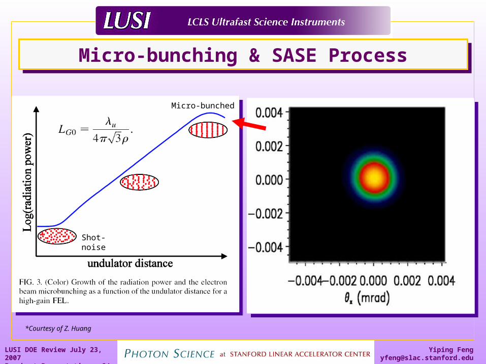
X-ray amplification process based on self-seeding SASE*
Lasing starts from a random electron density distributionEach X-ray pulse consists of a random time sequence of spikes of varying degrees of saturation
X-ray FEL exhibits inherent Intensity, spatial, temporal, and spectral fluctuations on pulse by pulse basis
*Self Amplification of Spontaneous Emission
Page 4
Yiping [email protected]
LUSI DOE Review July 23, 2007Breakout Presentations 4
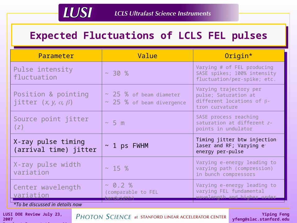
Expected Fluctuations of LCLS FEL pulsesExpected Fluctuations of LCLS FEL pulses
Parameter Value Origin*
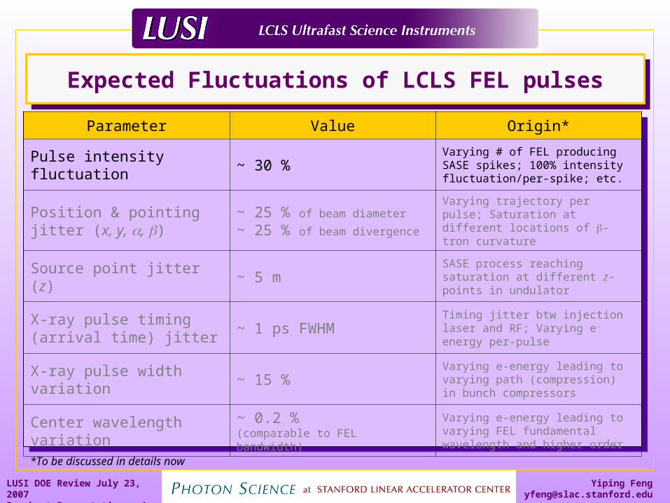
Pulse intensity fluctuation ~ 30 %Varying # of FEL producing SASE spikes; 100% intensity fluctuation/per-spike; etc.
Position & pointing jitter (x, y, , )
~ 25 % of beam diameter
~ 25 % of beam divergence
Varying trajectory per pulse; Saturation at different locations of -tron curvature
Source point jitter (z) ~ 5 m SASE process reaching saturation at different z-points in undulator
X-ray pulse timing (arrival time) jitter
~ 1 ps FWHMTiming jitter btw injection laser and RF; Varying e-energy per-pulse
X-ray pulse width variation
~ 15 %Varying e-energy leading to varying path (compression) in bunch compressors
Center wavelength variation
~ 0.2 % (comparable to FEL bandwidth)
Varying e-energy leading to varying FEL fundamental wavelength and higher order
*To be discussed in details now
Page 5
Yiping [email protected]
LUSI DOE Review July 23, 2007Breakout Presentations 5
Expected Fluctuations of LCLS FEL pulsesExpected Fluctuations of LCLS FEL pulses
Parameter Value Origin*
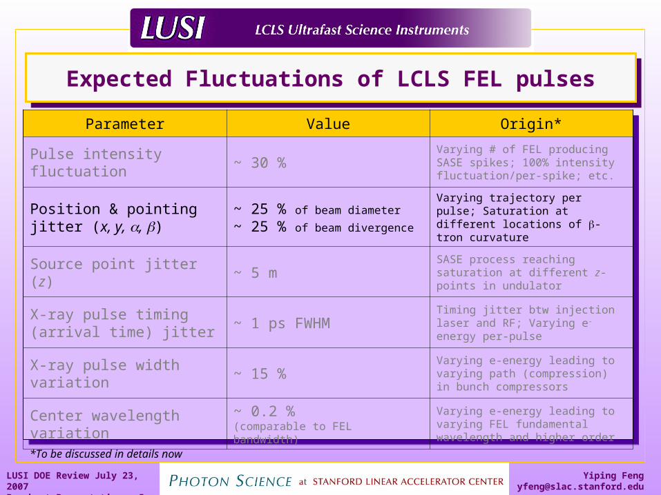
Pulse intensity fluctuation ~ 30 %Varying # of FEL producing SASE spikes; 100% intensity fluctuation/per-spike; etc.
Position & pointing jitter (x, y, , )
~ 25 % of beam diameter
~ 25 % of beam divergence
Varying trajectory per pulse; Saturation at different locations of -tron curvature
Source point jitter (z) ~ 5 m SASE process reaching saturation at different z-points in undulator
X-ray pulse timing (arrival time) jitter
~ 1 ps FWHMTiming jitter btw injection laser and RF; Varying e-energy per-pulse
X-ray pulse width variation
~ 15 %Varying e-energy leading to varying path (compression) in bunch compressors
Center wavelength variation
~ 0.2 % (comparable to FEL bandwidth)
Varying e-energy leading to varying FEL fundamental wavelength and higher order
*To be discussed in details now
Page 6
Yiping [email protected]
LUSI DOE Review July 23, 2007Breakout Presentations 6
Transverse JitterTransverse Jitter
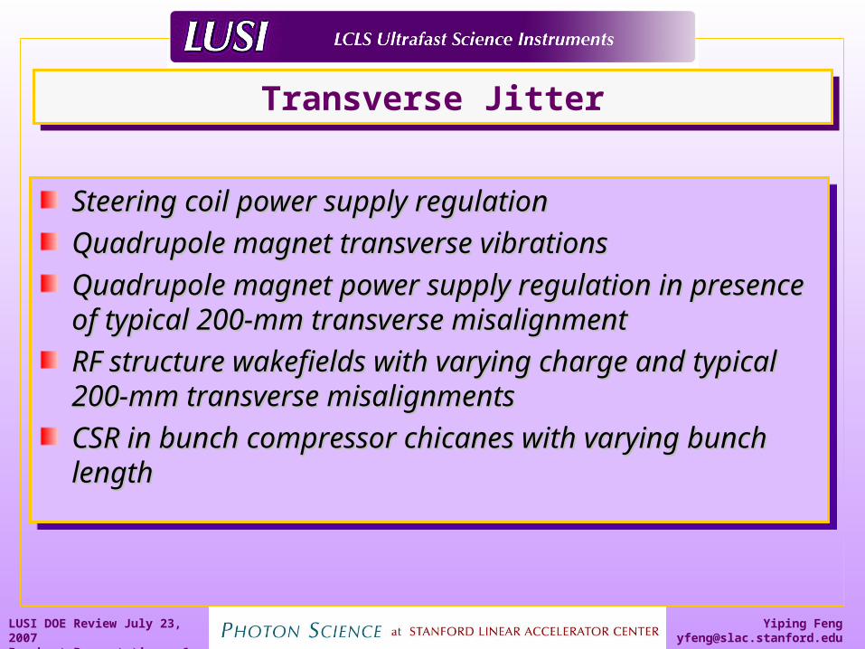
Steering coil power supply regulationSteering coil power supply regulation
Quadrupole magnet transverse vibrationsQuadrupole magnet transverse vibrations
Quadrupole magnet power supply regulation in Quadrupole magnet power supply regulation in presence of typical 200-mm transverse presence of typical 200-mm transverse misalignmentmisalignment
RF structure wakefields with varying charge and RF structure wakefields with varying charge and typical 200-mm transverse misalignmentstypical 200-mm transverse misalignments
CSR in bunch compressor chicanes with varying CSR in bunch compressor chicanes with varying bunch lengthbunch length
Page 7
Yiping [email protected]
LUSI DOE Review July 23, 2007Breakout Presentations 7
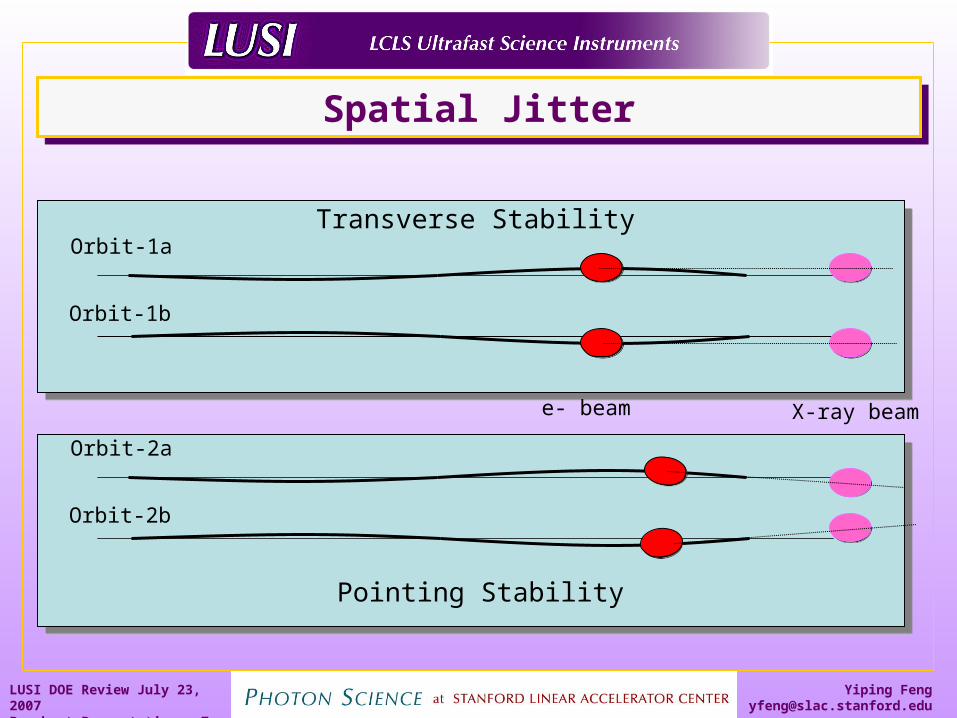
Spatial JitterSpatial Jitter
Orbit-1a
Orbit-1b
Orbit-2a
Orbit-2b
X-ray beame- beam
Transverse Stability
Pointing Stability
Page 8
Yiping [email protected]
LUSI DOE Review July 23, 2007Breakout Presentations 8
Expected Fluctuations of LCLS FEL pulsesExpected Fluctuations of LCLS FEL pulses
Parameter Value Origin*
Pulse intensity fluctuation ~ 30 %Varying # of FEL producing SASE spikes; 100% intensity fluctuation/per-spike; etc.
Position & pointing jitter (x, y, , )
~ 25 % of beam diameter
~ 25 % of beam divergence
Varying trajectory per pulse; Saturation at different locations of -tron curvature
Source point jitter (z) ~ 5 m SASE process reaching saturation at different z-points in undulator
X-ray pulse timing (arrival time) jitter
~ 1 ps FWHMTiming jitter btw injection laser and RF; Varying e-energy per-pulse
X-ray pulse width variation
~ 15 %Varying e-energy leading to varying path (compression) in bunch compressors
Center wavelength variation
~ 0.2 % (comparable to FEL bandwidth)
Varying e-energy leading to varying FEL fundamental wavelength and higher order
*To be discussed in details now
Page 9
Yiping [email protected]
LUSI DOE Review July 23, 2007Breakout Presentations 9
Z-JitterZ-Jitter
z
R2 = R1(R2/R1)2
R2 = Z
R1 R2
R2
Page 10
Yiping [email protected]
LUSI DOE Review July 23, 2007Breakout Presentations 10
Expected Fluctuations of LCLS FEL pulsesExpected Fluctuations of LCLS FEL pulses
Parameter Value Origin*
Pulse intensity fluctuation ~ 30 %Varying # of FEL producing SASE spikes; 100% intensity fluctuation/per-spike; etc.
Position & pointing jitter (x, y, , )
~ 25 % of beam diameter
~ 25 % of beam divergence
Varying trajectory per pulse; Saturation at different locations of -tron curvature
Source point jitter (z) ~ 5 m SASE process reaching saturation at different z-points in undulator
X-ray pulse timing (arrival time) jitter
~ 1 ps FWHMTiming jitter btw injection laser and RF; Varying e-energy per-pulse
X-ray pulse width variation
~ 15 %Varying e-energy leading to varying path (compression) in bunch compressors
Center wavelength variation
~ 0.2 % (comparable to FEL bandwidth)
Varying e-energy leading to varying FEL fundamental wavelength and higher order
*To be discussed in details now
Page 11
Yiping [email protected]
LUSI DOE Review July 23, 2007Breakout Presentations 11
Expected Fluctuations of LCLS FEL pulsesExpected Fluctuations of LCLS FEL pulses
Parameter Value Origin*
Pulse intensity fluctuation ~ 30 %Varying # of FEL producing SASE spikes; 100% intensity fluctuation/per-spike; etc.
Position & pointing jitter (x, y, , )
~ 25 % of beam diameter
~ 25 % of beam divergence
Varying trajectory per pulse; Saturation at different locations of -tron curvature
Source point jitter (z) ~ 5 m SASE process reaching saturation at different z-points in undulator
X-ray pulse timing (arrival time) jitter
~ 1 ps FWHMTiming jitter btw injection laser and RF; Varying e-energy per-pulse
X-ray pulse width variation
~ 15 %Varying e-energy leading to varying path (compression) in bunch compressors
Center wavelength variation
~ 0.2 % (comparable to FEL bandwidth)
Varying e-energy leading to varying FEL fundamental wavelength and higher order
*To be discussed in details now
Page 12
Yiping [email protected]
LUSI DOE Review July 23, 2007Breakout Presentations 12
GoalsGoals
X-ray diagnostics are required to measure these fluctuations since they can’t be eliminated
Integral parts of InstrumentsTiming & intensity measurements for XPP experimentsWave-front characterization for CXI experiments
Measurements made on pulse-by-pulse basisRequiring real-time processing by controls/data systems
Commonalities in needs & specsStandardized and used for all applicable instrumentsModularized for greater flexibility of deployment and placement
Critical diagnostics must be performed and data made available on pulse-by-pulse basis
Page 13
Yiping [email protected]
LUSI DOE Review July 23, 2007Breakout Presentations 13
Fluctuations, 120 hz pulse rate drive DAQ requirementsFluctuations, 120 hz pulse rate drive DAQ requirements
The 120 Hz per-pulse data collection/reduction, high data rate, large data volume, and sub-ps timing control requirements of LCLS experiments go far beyond those at existing synchrotron sources, requiring considerable complexity and sophistication in controls and data systems’ design, implementation, and integration that are not feasible for individual experimental teams
LCLS/LUSI controls and data systems mustProvide standard controls to all instrumentsSupport diagnostic measurementsProvide standard data acquisition capabilitiesProvide standard data storage and management capabilitiesProvide certain standard data analysis capabilities
Page 14
Yiping [email protected]
LUSI DOE Review July 23, 2007Breakout Presentations 14
Data system requirementsData system requirements
Data acquisitionReal-time data processingQuick view
Data managementOn-line storageLong term archiving/retrieval
Data analysisVolume renderingvisualization
Data acquisitionReal-time data processingQuick view
Data managementOn-line storageLong term archiving/retrieval
Data analysisVolume renderingvisualization
Page 15
Yiping [email protected]
LUSI DOE Review July 23, 2007Breakout Presentations 15
2D Detectors2D Detectors
Cornell (PAD) BNL(XAMPS)
Technology diode/ASIC diode/ASIC
Architecture Bump-bond integrated
readout pixel column
size 190x190x32 1024x1024
Data rate 1.9Gb/s 1.5Gb/s
Resolution 14bit 12bit
Plug-play with a common interface?
Page 16
Yiping [email protected]
LUSI DOE Review July 23, 2007Breakout Presentations 16
Data rates - CXIData rates - CXI
Data Rate/Volume of CXI Experiment(comparable to other experiments)
LCLS Pulse Rep Rate (Hz) 120
Detector Size (Megapixel) 1.2
Intensity Depth (bit) 14
Success Rate (%) 30%
Ave. Data Rate (Gigabit/s) 0.6
Peak Data Rate (Gigabit/s) 1.9
Daily Duty Cycle (%) 50%
Accu. for 1 station (TB/day) 3.1
require high performance and high capacity data acquisition and management system
Is it possible to perform real-time data analysisto reduce the data rate?
high peak rate & large volume comparable to high-energy physics experiments such as BaBar @ SLAC
Page 17
Yiping [email protected]
LUSI DOE Review July 23, 2007Breakout Presentations 17
Long term data storage needsLong term data storage needs
Year 2009- 2012- 2015-
Rep Rate (Hz) 120 120 120
Detector Size(Megapixel)
0.58 1.16 Projected 5.8
Intensity Depth (bit) 14 14 14
Success Rate (%) 10% 30% 50%
Ave. Data Rate (Gigabit/s) 0.1 0.58 4.9
Peak Data Rate (Gigabit/s) 0.97 1.94 9.8
Daily Duty Cycle (%) 25% 50% 75%
Accu. for 1 station (TB/day) 0.26 3.14 39
Accu. for 3 stations (TB/day) 0.80 9.4 118
Yearly Uptime (%) 25% 50% 75%
Accu. (Petabyte/year) 0.072 1.7 32
Duration/Lifetime (year) 3 3 3
Total Accu. (Petabyte) 0.22 5.2 97
Page 18
Yiping [email protected]
LUSI DOE Review July 23, 2007Breakout Presentations 18
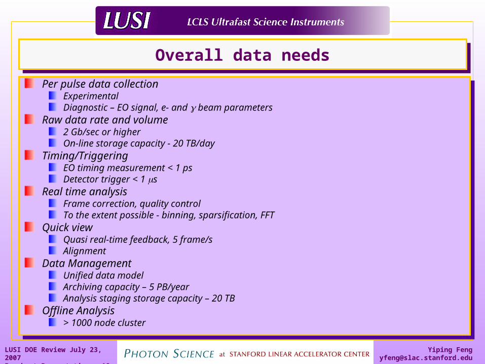
Overall data needsOverall data needs
Per pulse data collectionExperimentalDiagnostic – EO signal, e- and beam parameters
Raw data rate and volume2 Gb/sec or higherOn-line storage capacity - 20 TB/day
Timing/TriggeringEO timing measurement < 1 psDetector trigger < 1 s
Real time analysisFrame correction, quality controlTo the extent possible - binning, sparsification, FFT
Quick viewQuasi real-time feedback, 5 frame/sAlignment
Data ManagementUnified data modelArchiving capacity – 5 PB/yearAnalysis staging storage capacity – 20 TB
Offline Analysis> 1000 node cluster
Page 19
Yiping [email protected]
LUSI DOE Review July 23, 2007Breakout Presentations 19
Applications needs Applications needs
User programsEndstation operationCalibrationAlignment
Interface to SW for diffraction/scattering experimentsSPEC
Interface to instrumentation/analysis SWMatLabLabView
User toolsSTRIP toolALARM Handler
User programsEndstation operationCalibrationAlignment
Interface to SW for diffraction/scattering experimentsSPEC
Interface to instrumentation/analysis SWMatLabLabView
User toolsSTRIP toolALARM Handler
Page 20
Yiping [email protected]
LUSI DOE Review July 23, 2007Breakout Presentations 20
Pieces of the PuzzlePieces of the Puzzle
LUSI Control
& Data System
Control Subsystemfor Operation
& Controls
Data Subsystemfor Acquisition & Management
LCLSControl System
Controlsfor RF/Undulator
SLACSci. Computing
& Computing Srvs.
Data Farm(PB Tape Drive)
Computer Cluster(2000 processor Node)
Data Archiving/RetrievalOffline Analysis/Rendering
EO Timing & TriggeringFeedback
High peak rate/large volume
Pulse-by-pulseinfo exchange
Page 21
Yiping [email protected]
LUSI DOE Review July 23, 2007Breakout Presentations 21
Page 22
Yiping [email protected]
LUSI DOE Review July 23, 2007Breakout Presentations 22
LCLS FEL ParametersLCLS FEL Parameters
*Courtesy of Z. Huang
Page 23
Yiping [email protected]
LUSI DOE Review July 23, 2007Breakout Presentations 23
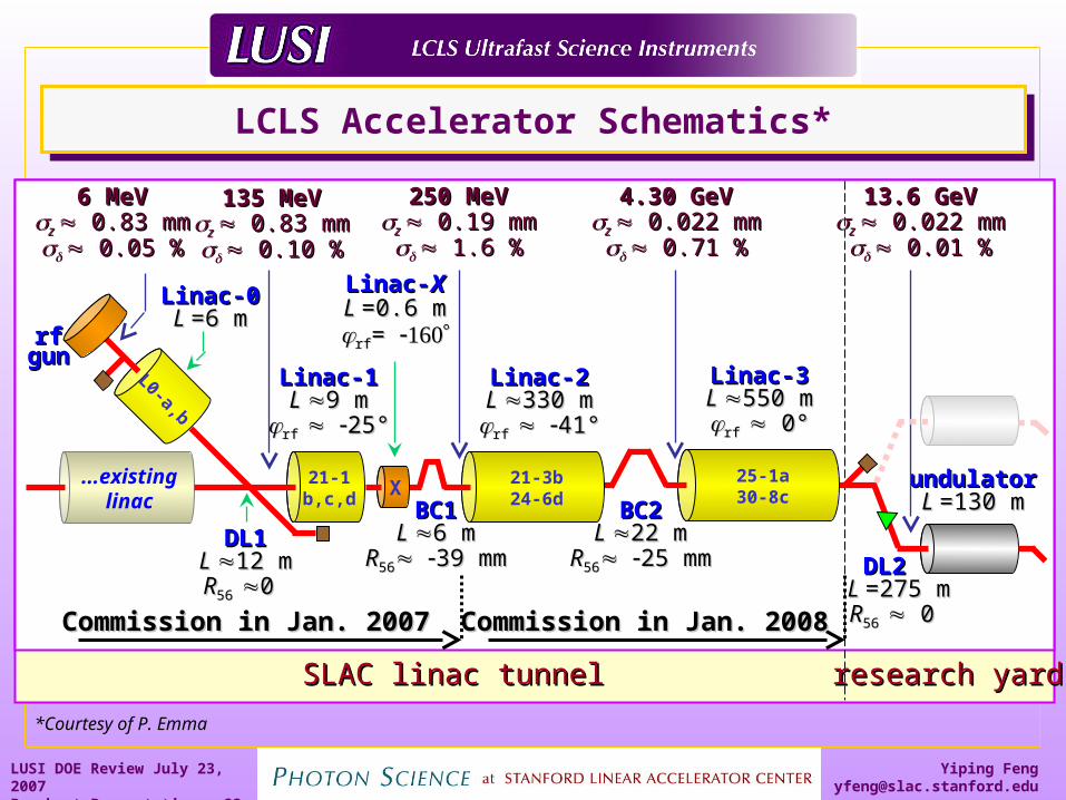
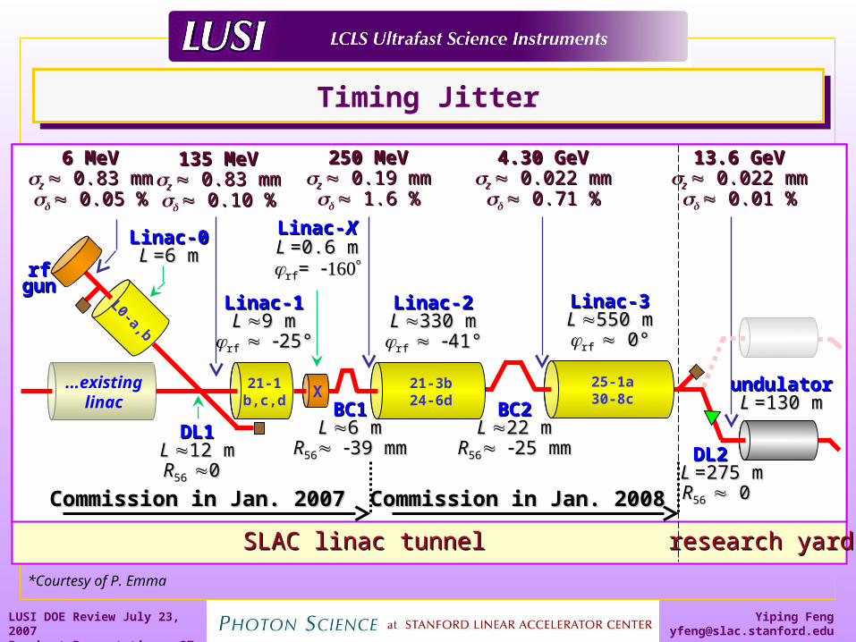
SLAC linac tunnelSLAC linac tunnel research yardresearch yard
Linac-0Linac-0L L =6 m=6 m
Linac-1Linac-1L L 9 m9 m
rf rf 25°25°
Linac-2Linac-2L L 330 m330 mrf rf 41°41°
Linac-3Linac-3L L 550 m550 mrf rf 0° 0°
BC1BC1L L 6 m6 m
RR5656 39 mm39 mm
BC2BC2L L 22 m22 m
RR5656 25 mm25 mm DL2 DL2 L L =275 m=275 mRR56 56 0 0
DL1DL1L L 12 m12 mRR56 56 0 0
undulatorundulatorL L =130 m=130 m
6 MeV6 MeVz z 0.83 mm 0.83 mm 0.05 %0.05 %
135 MeV135 MeVz z 0.83 mm 0.83 mm 0.10 %0.10 %
250 MeV250 MeVz z 0.19 mm 0.19 mm 1.6 %1.6 %
4.30 GeV4.30 GeVz z 0.022 mm 0.022 mm 0.71 %0.71 %
13.6 GeV13.6 GeVz z 0.022 mm 0.022 mm 0.01 %0.01 %
Linac-Linac-XXL L =0.6 m=0.6 mrfrf= =
21-1b,c,d
...existinglinac
L0-a,b
rfrfgungun
21-3b24-6dX
25-1a30-8c
Commission in Jan. 2007Commission in Jan. 2007 Commission in Jan. 2008Commission in Jan. 2008
LCLS Accelerator Schematics*LCLS Accelerator Schematics*
*Courtesy of P. Emma
Page 24
Yiping [email protected]
LUSI DOE Review July 23, 2007Breakout Presentations 24
Micro-bunching & SASE ProcessMicro-bunching & SASE Process
*Courtesy of Z. Huang
Micro-bunched
Shot-noise
Page 25
Yiping [email protected]
LUSI DOE Review July 23, 2007Breakout Presentations 25
Temporal CharacteristicTemporal Characteristic
T = 100 - 200 fstc ~ 200 as
M = T/tc ~ 500 -1000
For ideal e-beam of equal bunch length and same energy
<I/I> ~ 1/√M ~ 5%
In reality<I/I> ~ 1/√M ~ 30%
T = 100 - 200 fstc ~ 200 as
M = T/tc ~ 500 -1000
For ideal e-beam of equal bunch length and same energy
<I/I> ~ 1/√M ~ 5%
In reality<I/I> ~ 1/√M ~ 30%
*Courtesy of Z. Huang
200-300 attosecond
Page 26
Yiping [email protected]
LUSI DOE Review July 23, 2007Breakout Presentations 26
Magnetic Bunch CompressionMagnetic Bunch Compression
zz00
zzzz
under-under-compressioncompression
VV = = VV00sin(sin())
RF AcceleratingRF AcceleratingVoltageVoltage
RF AcceleratingRF AcceleratingVoltageVoltage
zz = = RR5656
Path Length-EnergyPath Length-EnergyDependent BeamlineDependent Beamline
Path Length-EnergyPath Length-EnergyDependent BeamlineDependent Beamline
……or over-or over-compressioncompression
zz
EE//EE
zz
‘‘chirp’chirp’
Page 27
Yiping [email protected]
LUSI DOE Review July 23, 2007Breakout Presentations 27
SLAC linac tunnelSLAC linac tunnel research yardresearch yard
Linac-0Linac-0L L =6 m=6 m
Linac-1Linac-1L L 9 m9 m
rf rf 25°25°
Linac-2Linac-2L L 330 m330 mrf rf 41°41°
Linac-3Linac-3L L 550 m550 mrf rf 0° 0°
BC1BC1L L 6 m6 m
RR5656 39 mm39 mm
BC2BC2L L 22 m22 m
RR5656 25 mm25 mm DL2 DL2 L L =275 m=275 mRR56 56 0 0
DL1DL1L L 12 m12 mRR56 56 0 0
undulatorundulatorL L =130 m=130 m
6 MeV6 MeVz z 0.83 mm 0.83 mm 0.05 %0.05 %
135 MeV135 MeVz z 0.83 mm 0.83 mm 0.10 %0.10 %
250 MeV250 MeVz z 0.19 mm 0.19 mm 1.6 %1.6 %
4.30 GeV4.30 GeVz z 0.022 mm 0.022 mm 0.71 %0.71 %
13.6 GeV13.6 GeVz z 0.022 mm 0.022 mm 0.01 %0.01 %
Linac-Linac-XXL L =0.6 m=0.6 mrfrf= =
21-1b,c,d
...existinglinac
L0-a,b
rfrfgungun
21-3b24-6dX
25-1a30-8c
Commission in Jan. 2007Commission in Jan. 2007 Commission in Jan. 2008Commission in Jan. 2008
Timing JitterTiming Jitter
*Courtesy of P. Emma
Page 28
Yiping [email protected]
LUSI DOE Review July 23, 2007Breakout Presentations 28
X-ray Diagnostics SuiteX-ray Diagnostics Suite
Fluctuation Type Diagnostic Device
Pulse intensity fluctuationa) Pop-In Intensity Monitorb) In-Situ BPM/Intensity Monitor
Position & pointing jitterc) Pop-In Position/Profile MonitorIn-Situ BPM/Intensity Monitor- Pointing determination from multiple BMP’s
Source point jitter Focal point jitter w/ focusing optics
d) Wave-front Sensor- Back-propagating from radius of curvature measurement
X-ray pulse timing jittere) Electro-Optic Sampling (EOS) Device- Relative timing btw e-bunch & ref. probe laser
X-ray pulse width variation EOS Device- Establishes upper limit
center wavelength variation LCLS e-energy calibration- X-ray wavelength cross-calibration is needed
Page 29
Yiping [email protected]
LUSI DOE Review July 23, 2007Breakout Presentations 29
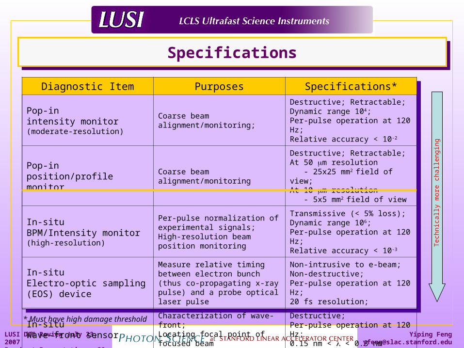
SpecificationsSpecifications
Diagnostic Item Purposes Specifications*
Pop-inintensity monitor(moderate-resolution)
Coarse beam alignment/monitoring;
Destructive; Retractable;Dynamic range 104;Per-pulse operation at 120 Hz;Relative accuracy < 10-2
Pop-inposition/profile monitor
Coarse beam alignment/monitoring
Destructive; Retractable;At 50 m resolution - 25x25 mm2 field of view;At 10 m resolution - 5x5 mm2 field of view
In-situBPM/Intensity monitor(high-resolution)
Per-pulse normalization of experimental signals;High-resolution beam position monitoring
Transmissive (< 5% loss); Dynamic range 106;Per-pulse operation at 120 Hz;Relative accuracy < 10-3
In-situ Electro-optic sampling (EOS) device
Measure relative timing between electron bunch (thus co-propagating x-ray pulse) and a probe optical laser pulse
Non-intrusive to e-beam;Non-destructive; Per-pulse operation at 120 Hz;20 fs resolution;
In-situWave-front sensor
Characterization of wave-front;Locating focal point of focused beam
Destructive; Per-pulse operation at 120 Hz;0.15 nm < < 0.3 nm
* Must have high damage threshold
Tech
nic
ally
more
ch
alle
ng
ing
Page 30
Yiping [email protected]
LUSI DOE Review July 23, 2007Breakout Presentations 30
Data Processing Data Processing
GoalsSystem Specifications for Data System
Data Acquisition and Management
Data AnalysisXPP, CXI, and XCS Instruments
System Description Gunther Haller’s breakout session
GoalsSystem Specifications for Data System
Data Acquisition and Management
Data AnalysisXPP, CXI, and XCS Instruments
System Description Gunther Haller’s breakout session
Page 31
Yiping [email protected]
LUSI DOE Review July 23, 2007Breakout Presentations 31
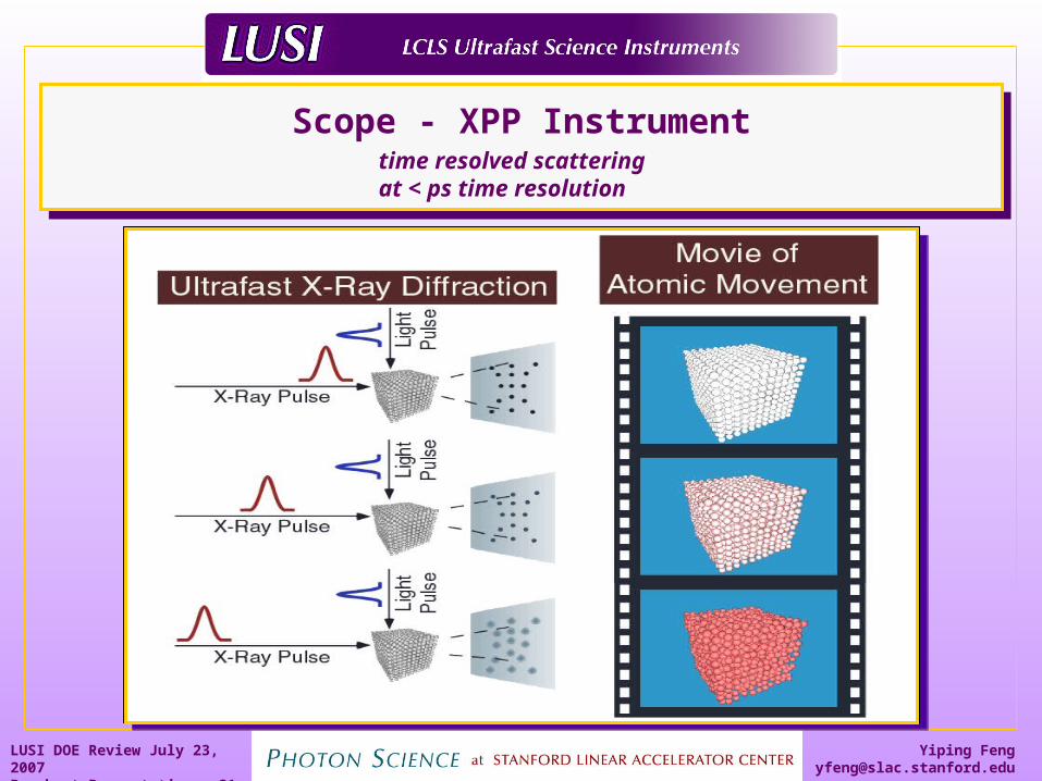
Scope - XPP InstrumentScope - XPP Instrumenttime resolved scatteringat < ps time resolution
Page 32
Yiping [email protected]
LUSI DOE Review July 23, 2007Breakout Presentations 32
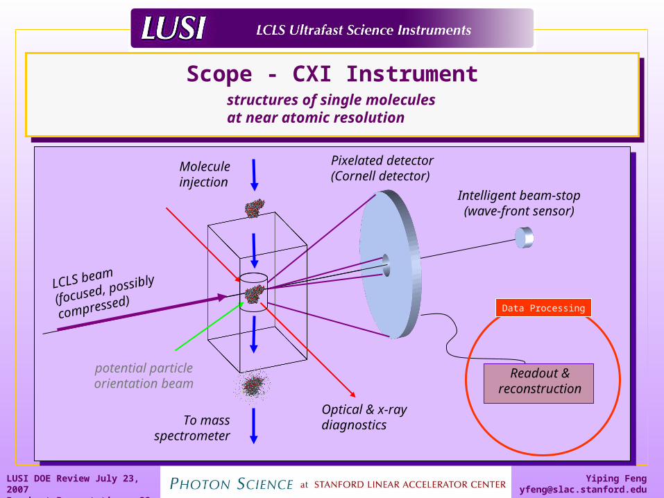
Molecule injection
LCLS beam
(focused, possibly
compressed)
Optical & x-ray diagnostics
Pixelated detector(Cornell detector)
Intelligent beam-stop(wave-front sensor)
To mass spectrometer
potential particle orientation beam
Scope - CXI Instrument
Scope - CXI Instrument
Readout & reconstruction
structures of single moleculesat near atomic resolution
Data Processing
Page 33
Yiping [email protected]
LUSI DOE Review July 23, 2007Breakout Presentations 33
Scope - PCS InstrumentScope - PCS Instrument
Speckle Pattern (Iron-Aluminum Alloy)
dynamics of disordered systemsat < ns time & near atomic resolutions
Data Processing
Page 34
Yiping [email protected]
LUSI DOE Review July 23, 2007Breakout Presentations 34
Diagnostics Control - Hartman Wavefront SensorDiagnostics Control - Hartman Wavefront Sensor
Measurement made far from focal planeSingle shot operation120 Hz with CCD modification1.5 nm and 0.15 nm operation with customization
Measurement made far from focal planeSingle shot operation120 Hz with CCD modification1.5 nm and 0.15 nm operation with customization
Image obtained from Imagine Optics, Ltd
Page 35
Yiping [email protected]
LUSI DOE Review July 23, 2007Breakout Presentations 35
• Coax RF distribution Network• e-beam phase to RF phase• End Station Laser phase to RF phase
Limited to ~ 1 ps !
Sources of Short Term Jitter
AcceleratingElements
ExperimentalPump Laser
Electron Gun
Master Clock Coax RF
Distribution Network
Timing Control - Temporal JitterTiming Control - Temporal Jitter
Page 36
Yiping [email protected]
LUSI DOE Review July 23, 2007Breakout Presentations 36
Timing Control - Electro-optic SamplingTiming Control - Electro-optic Sampling
Electro-optic Sampling
Laser
Pump-probe
Laser
LTU NEH
Temporal resolution is now limited by:
1) Our ability to phase lock the lasers to the RF
2) Intra-bunch SASE jitter
Gun Laser
Sector 20
Stabilized Fiber Optic RF Distribution (10 fs)
LBNL
Page 37
Yiping [email protected]
LUSI DOE Review July 23, 2007Breakout Presentations 37
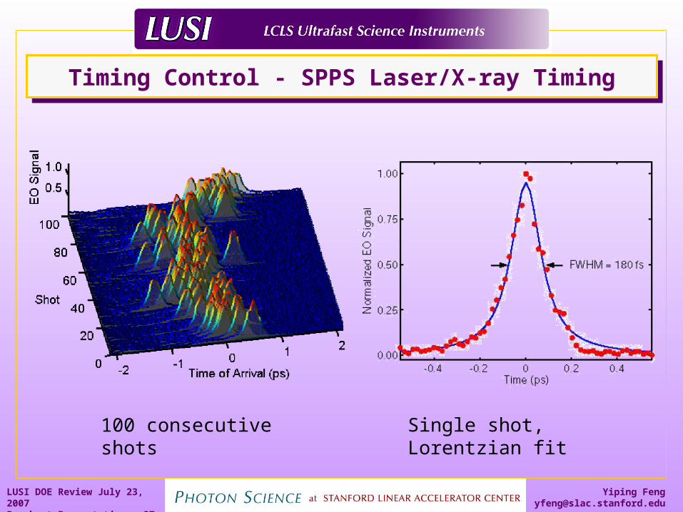
Timing Control - SPPS Laser/X-ray TimingTiming Control - SPPS Laser/X-ray Timing
100 consecutive shots
Single shot, Lorentzian fit
Page 38
Yiping [email protected]
LUSI DOE Review July 23, 2007Breakout Presentations 38
Real-time Processing – Binning in XPPReal-time Processing – Binning in XPP
Page 39
Yiping [email protected]
LUSI DOE Review July 23, 2007Breakout Presentations 39
Real-time processing – binning in XPPReal-time processing – binning in XPP
• 10 Hz• Point Detector
For XPP experiments using 2D detector,Is it possible to perform real-time data analysisto reduce the data rate?
Page 40
Yiping [email protected]
LUSI DOE Review July 23, 2007Breakout Presentations 40
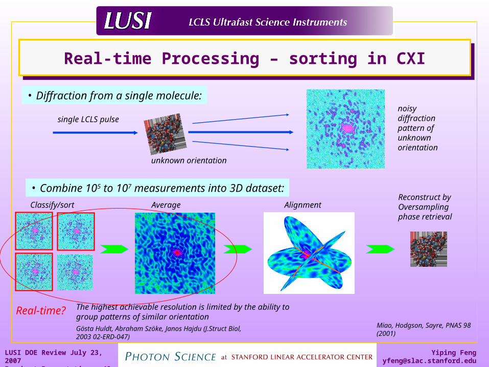
Real-time Processing – sorting in CXIReal-time Processing – sorting in CXI
• Diffraction from a single molecule:
single LCLS pulsenoisydiffractionpattern of unknown orientation
• Combine 105 to 107 measurements into 3D dataset:
Classify/sort Average AlignmentReconstruct by Oversampling phase retrieval
Miao, Hodgson, Sayre, PNAS 98 (2001)
unknown orientation
Gösta Huldt, Abraham Szöke, Janos Hajdu (J.Struct Biol, 2003 02-ERD-047)
The highest achievable resolution is limited by the ability to group patterns of similar orientation
Real-time?
Page 41
Yiping [email protected]
LUSI DOE Review July 23, 2007Breakout Presentations 41
Computing hardware requirementsComputing hardware requirements
Real-time computingPower: 10 Tera-FLOPS
1000 processor clusterMemory: 10 -100 GByte RAMBandwidth: 100 Gbit/sIntegrated w/ detector or immediate downstream of detector output
Data Storage/Management10 – 100 Gbit/s links10 – 100 on-line capacity: RAID disks, or flash memory10 – 100 staging capacity: RAID disks, or flash memory5 Petabyte yearly capacityESNET connection for transferring to sister institutes
Offline AnalysisTotal FLOPs: 1017 If analysis done in minutes: 2000 – 40000 processor clusterLarge volume set rendering: 109