AD-A267 555 FORMULATING INFRARED COATINGS FOR DEFENCE APPLICATIONS L.V. WAKE AND R.F. BRADY MRL-RR-1 -93 MARCH 1993 PTc r_ _ _ A 4PPROVED AOUL FOR PUBLIC RELEASI ,i _ M'ATERIALS RESEARCH LABu"RATOR DSTO
Relevant physical laws governing the response of coatings to solar and inf'ared radiationhave been reviewed. The reflection of infrared radiation by a paint is cLonitrolled primnarilyby the refractive index and particle size ofthe pigments in the coating. l'igments havebeen evaluated for reflectance, transparence and hiding power in the near inf*rared region,and guidelines 'or pigment selection fbr various applications given in terms qftheir opticalproperties in the near infrared region. Raw materials selection, mnaniracture andevaluation qf coatings have been discussed with respect to tailoring infrared reflectance.Byv employing the principles developed herein and using pigments with appropriateproperties, organic coatings have been developed which are consistent with the visiblecolour requirements of the Australian and US Navies. Significant increases in thereflection of infrared radiation have been demonstrated by the new formulations. Theneed for a very clear understanding of the threat systems and the operational conditions ofservice platforms has been emphasised. It is only with this understanding that optintionpaint schemes can be devised. However, it can be stated that the use of the solar in 'fraredreflecting paints described herein would reduce conspicuity of isolated ,'latforms tosurveillance and seeker systems operating in the mid and far infrared without detrimenit tovisual camouflage characteristics.
93-16625
ke :'ý " tj
DSTO MATERIALS RESEARCH LABORATCRYI i
Publ.sished by
DSTO Materials Research LaboratoryCordite Avenue, MaribyrnongVictoria, 3032 Australia
Lindsay Vernon Wake was awarded a Department ofSupply scholarship to complete a PhD at the University ofNSW in 1969. He joined MRL in 1972 and was brieflyassociated with the Textiles Group and later the Marine
* Environment Group of MRL. Since 1981, Dr Wake hasbeen located in Paint Technology where he has formed aclose working association with the RAAF. He iscurrently investigating the synthesis and pertbrmance offire retardant paints, high temperature resistant coatings,RF and IR camouflage paints and other coating materialsof Defence interest.
R.F. Brady
In 1982 Dr Brady assumed his present position as Head ofthe Coatings Section of the US Naval ResearchLaboratory. He directs and conducts basic research inpolymer chemistry and coatings science. His presentinterests include control of volume change duringpolymerization, coatings based on fluorinated resins,high-solids epoxy and polyurethane coatings,, non-toxicantifouling coatings, and non-skid coatings for aircraftcarriers. For one year beginning in July 1990, he was avisiting scientist at MRL, where he worked on theformulation of coatings with tailored infrared properties.
Aooosalon forXITIS GRA&I •"i
DTIC TAB 0Unannoun•oed 0Justifioation
D9strIbutlon/
Avallabillty 0odesSAvail and/or
Q17AM Z8P~rD 1910 Specilal
D27OQYPAZrJ,, IfV
Contents
1. INTRODUCTION 7
2. PHYSICAL PRINCIPLES 82.1 Spectral Bands of Interest 82.2 Blackbody Radiation 82.3 Solar Radiation 102.4 Control of Infrared Properties by Coating Formulation 102.5 Properties of Coatings Determining Infrared Performance 12
2.5.1 Reflection of Radiation 122.5.2 Scattering of Radiation 132.5.3 Absorption of Radiation 14
3. RAW MATERIALS 153.1 Measurement of Near Infrared Properties of Pigments 153.2 Selecting Pigmentsfor Applications in the Near Infrared 193.3 Selecting Pigments for Applications in the Thermal Infrared 213.4 Spectral Properties of Resins 22
4. FORMULATION 224.1 Preparing for Formulation 224.2 Control of Colour 234.3 Control of Emissivity in the Thermal Infrared 23
5. COATINGS WITH TAILORED INFRARED REFLECTANCE 245.1 Low NIR or Low TIR Signature? 245.2 Solar Heat (near infrared) Reflecting Coatings 245.3 Thermal Infrared Reflecting (low emissivity) Coatings 255.4 Camouflage Coatings 25
5.4.1 Coatings for Forest and Jungle Areas 265.4.2 Coatings for Desert Regions 295.4,3 Coatings for Ocean Environments 295.4.4 Coatings for Aircraft 31
The short electromagnetic wavelengths which characterize near and thermalinfrared radiation permit the use of thin coatings to control absorption andreflection of radiation in these regions. Paints can be designed which increase thereflection of incident solar radiation while retaining the visible properties ofcolour and gloss. The increased reflection reduces heating and lowers the energyrequirements for cooling. In other instances, paints may be required to reduce theemission of thermal infrared radiation and shift infrared emissions to differentwavelengths, thus reducing the likelihood of detection. Coatings may also beformulated to combine reduced emissions in the thermal region with reducedreflection in NIR bands used for laser detection.
Requirements to control infrared properties of coatings arose after thedevelopment of infrared photography. This need led to changes in paintformulation aimed at reducing reflection in the near infrared (NIR) regionbetween 720 and 900 nm. With the increasing use of infrared detectors, paintspecifications have retained the requirement for low infrared reflection. However,low NIR reflecting paints strongly absorb the NIR component of solar radiation.As such, they increase thermal infrared (TIR) signatures and the likelihood of TIRdetection as well as adding to the cooling requirements. At the present time, theoptimum balance for NIR or TIR signatures has received little attention.
This report examines mechanisms influencing the reflection, transmission andabsorption of visible and infrared radiation by paint coatings. The report details anumber of new paint formulations to meet defence coating requirements whichsignificantly reduce thermal emissions. Consideration is also given to theselection of formulations to meet different combinations of threats andenvironments.
2. Physical Principles
2.1 Spectral Bands of Interest
The radiation bands of interest are the NIR region between 720 and 2500 nm, theTIR region between 2500 and 15 000 run (2.5 and 15 mm), and the far infraredregion between 15 and 50 mm.
The "photographic infrared" is traditionally regarded as the range from 700 to950 ran, although modern infrared film is sensitive at much longer wavelengthsthan this range. Electronic scanning arrays are usually preferred overphotographic detectors. They are used in aerial reconnaissance and cover therange from 700 to 1350 nm. Generally, the conditions Linder which NIR radiationemissions pose a significant threat are (i) lowlight or starlight situations wheredetection is usually by reflected radiation rather than by thermal emission, or (ii)by reflection of NIR laser illumination.
Two windows in the thermal infrared region, 3 to 5 mm and 8 to 14 mm are ofprimary importance in missile and surveillance applications because these regionsare relatively free of atmospheric absorption and energy can be transmitted overmoderate distances. Sensors operating in these two bands are the basis of someof the principal types of seekers in smart anti- armour munitions [I 1.
Some of the newer thermal detection systems also incorporate NIR targetingelements. A number of the aircraft-mounted detection systems couple forwardlooking thermal infrared (FLIR) sensors tailored for target detection and lock-onwith a laser target designator and rangefinder operating in the NIR at 1.06 Pim.
2.2 Blackbody Radiation
In addition to reflecting incident energy, coatings also radiate energy. Thespectral exitance MX. (W.m'2 ) of a blackbody at wavelength X and in a spectralrange •X is a function of temperature and is given by Planck's Radiation Formula(Equation 1) 121
2nhc2 I11
X3 (ehc/kXT -1)
(in which h is Planck's constant (6.626 x 10⁻³⁴ J s), c the velocity of light (2.998 x10⁸ m s'-, k the Boltzmann constant (1.38 X 10⁻²³ J K-'), and T the absolutetemperature).
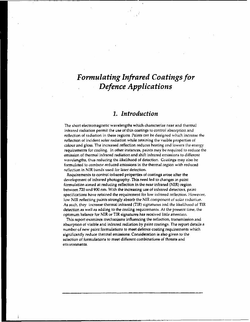
The rate of energy emitted per unit area obtained from Equation 1 has beenplotted for three temperatures in Figure 1. This figure shows that, with increasingtemperature, the rate emitted increases markedly and the wavelength ofmaximum emission shifts from the TIR region toward the NIR region. Thus, it canbe seen that an increase in the energy content of a body, such as that caused bythe absorption of NIR radiation, results in increased emission and detectability inthe 8 to 14 mm TIR region.
1400
1200 -
1000 -
600K* 800-Boo
), 600
C 50L'. 400 -SO
200 - 00K
00.5 1.0 5 10 50
Wavelength. um
Figure 1: Radiation energy at three temperatures.
Wher, Equation I is integrated over all wavelengths, the Stefan-Boltzmann Law(Equation 2) is obtained
W = aT4 (2a)
(in which a is the Stefan-Boltzmann constant (5.67 x 10⁻⁸ W m 2 K-4).For non-ideal systems, the total radiative emissions are proportional to the
emittance, e, of the surface and the equation describing the total power Wradiated by a body becomes
W = aoT4 (2b)
The emittance, c, of a surface is the ratio of its emission to that of an ideal blackbody at the same temperature and can vary from 0 to 1. The ernittance of metalssuch as aluminum and nickel as well as treated metal surfaces with thin oxidecoatings is typically in the range from 0.05 to 0.15 and these materials areinefficient radiators of energy. As well as being poor radiators of thermalradiation, polished metal surfaces are good reflectors of incident radiation. Theemittance of organic materials such as plastics and most organic coatings is high(0.85 to 0.95). When the ratio of the spectral emission of a surface to that of ablack body is constant with wavelength, the surface is known as a grey body. Inmost cases, the emissivity varies with wavelength and the coating is said to be aselective radiator.
9
2.3 Solar Radiation
A specific example of a blackbody radiator is the sun. The spectral energydistribution of solar radiation at sea level with .1 slant path corresponding to anair mass of 1.5 [31 is shown in Figure 2. For convenience, this energy is usuallydivided into three bands. The ultraviolet band between 200 and 400 nm contains5 percent of the total energy in sunlight, the visible band between 400 and 720 nmhas 45 percent and the NIR band between 720 and 2500 nm contains 50 percent ofthe energy. Sunlight at sea level has a total intensity of approximately 1 kW m. 2
[3]. Solar absorptance, a, in the NIR is defined as the ratio of NIR radiationabsorbed by a body to that incident upon it.
1400
1200
1000'a
8. 00
, 600
C=''' 400
200
00.5 1.0 5 10 50
Wavelength. um
Figure 2: Spectral eneriny distribution of solar radiation.
2.4 Control qf Infrared Properties by Coating f-ormulation
Incident radiation is reflected or both reflected and refracted at a coating surface.Both reflection and refraction are dependent on the refractive indices of the twomedia, the reflection being determined by Fresnel's Law and refraction by Snell'sLaw. In paint terminology, a description of the mirror-like reflection or specularreflection at the surface of the coating is termed gloss, as distinct from thereflectance of the coating which is also dependent on pigments and fillers in thecoating. Specular reflection is strongly increased by leafing pigments such asmetal flakes. Gloss is principally dependent on the angle of incidence and thesmoothness of the surface, being high for smooth surfaces and low for irregularsurfaces.
Infrared radiation entering a paint coating is refracted at the interface beforeencountering the pigment and filler particles. The radiation is partially reflectedand partially refracted at the surfaces of these particles and in normal pigmentedpaints the process of multiple reflection and refraction thoroughly diffuses tihebeam. A proportion of this radiation propagates back to the coatiig surface where
10
it leaves in all directions. Diffusion of radiation arises from a large number ofessentially random scattering events and in paint technology, the overall diffusionprocess is simply termed "scattering".
The selection of pigments largely determines the thermal control provided bycoatings. The most important aspects of these are the solar absorptance, a., inthe NIR and the emittance, e, in the TIR regions. Examples of specific thermalrequirements include (i) high solar absorptance to reduce photographic or NIRlaser detectibility, (ii) low solar absorptance to keep illuminated equipment coolin hot environments or, (iii) low emittance to reduce thermal detectability.Coatings may combine low emittance properties with either high or low levels ofsolar absorptance.
Camouflage of defence equipment in the visible waveband is usually achievedby the use of dark coloured low gloss paints. Dark coloured paints, e.g. navygreys, are commonly formulated with carbon black which is a strong absorber ofsolar radiation and reduces photographic and laser detectibility in the NIR.However, paints formulated with carbon black have high emissivities andstrongly emit thermal radiation. A number of metal oxide coatings applied tometal substrates combine high solar absorption with low emissivity in the TIR asthin oxide layers absorb short wavelength radiation but are transparent in thelonger wavelength infrared region. These absorption characteristics act to reducethe chance of detection in both TIR and NIR regions. However, as these coatingsstrongly absorb solar radiation, heat build-up may be a problem. By replacingcarbon black or the black metal oxides with organic perylene blacks which absorbweakly in the NIR, paints can be formulated in the same colours to reduce solarheating. Like the metal-metal oxide paints, the perylene black paints are selectiveabsorbers, however, whereas the metal-metal oxide paints absorb strongly in theNIR and poorly in the TIR, the perylene black coatings absorb weakly in the NIRregion and strongly in the TIR region. Low emittance paints may also beformulated with metal flakes, e.g. aluminium, which provide strong reflectionacross the visible and infrared spectrum.
The reduced thermal exitance resulting from either lower temperatures or lowemittance reduces the chances of thermal infrared detection. However, when thedetector system has both near and thermal detecting elements, such as in some ofthe air borne systems, the requirements involved in paint selection are morecomplex. Under normal conditions, the laser system has greater range than theTIR detectors. This imbalance permits active rangefinding well outside passiveacquisition range. The use of solar reflecting paints will accentuate the imbalanceby reducing the acquisition range while further increasing the active NIRrangefinding capability. Under normal daylight conditions this will lower thedetection range while having little effect at night. An alternative paint for thisapplication would be the NIR absorbing, low emittance metal-metal oxide paints.However, their use under Australian conditions, particularly in northernAustralia, would result in considerable heat build-up.
It should be appreciated from the above examples that paints may beformulated which provide either (i) absorption across the NIR and TIR regions,(II) reflection across the NIR and TIR regions, or (111) absorption in the NIR andreflection in the TIR region or vice versa.
11
2.5 Properties of Coatings Determining Infrared Performance
2.5.1 Reflection of Radiation
The specular and diffuse reflectance of infrared radiation from a coating resultsfrom reflecting and scattering processes occurring at the surface and within thecoating. The reflectivity is defined as the ratio of the reflected to the incidentenergy. At flat surfaces, specular reflection will occur in accordance with FresnersLaw from which the reflection coefficient (p) may be derived [41:
(n+ 1)2 +,1X 2
(in which n is the ratio between the refractive indices of the two media and X isthe extinction coefficient).
From Equation 3, we see that when ix is large (good absorbers) compared toii + 1, the reflecting power is nearly unity, i.e. strong reflection is associated withstrong absorption. This result is in agreement with experimental observation [51.Highly conductive materials, e.g. metals, do not allow electromagneticpropagation at optical or infrared frequencies. The electromagnetic fields arcattenuated so rapidly that, at thicknesses exceeding the skiii depth, the reflectioncoefficients are close to unity. However, metals in the form of very small particleswill allow the passage of-decaying electromagnetic fields, and because of theirhigh absorption, the emissivity of paints containing such particles may approachunity. The small particles will also provide diffuse multiple scattering,particularly when the particle sizes approach light wavelengths. This is the basisof the action of the metallic blacks.
From Kirchhoff's Law (Equation 4), it can be seen that coatings which are goodreflectors have low emissivities [61,
•. = I- k ]I- •,"4X•" •.](4)
(where eý is the emissivitv, p4 the fraction of the radiation refiected, 4r%, thieabsorption coefficient and t the depth). The first term in Kirchhoff's Equation.I - pk which is the proportion of radiant flux penetrating the body, becolmesquite small for good reflectors. The second term, I - emxx r/A is the proportion offlux penetrating the body and absorbed by it. In the infrared spectral region, evena small thickness of matter will usually absorb the entire refracted flux, so thatequation 4 reduces to
e = l-p). (5)
For materials of high conductivity, the reflectance (and emittance) can bereduced to equations dependent only on conductivity 171, viz
(where a is the conductivity and c the velocity of light).
12
Equation 6 is in close agreement with experimental observations [5]. It is seenthat the emittance of conducting materials decreases as the wavelength increasesand, in practice, paints with low thermal emissivities are usually formulated withmetal pigments. Flaked metal pigments are commonly chosen because they havelarge flat surfaces which maintain high reflectivity compared with smaller metalparticles.
2.5.2 Scattering of Radiation
Scattering of visible and infrared radiation is a single stage process and iscommonly referred to as being either elastic or inelastic. Scattering in which theradiation retains the same quantity of energy and momentum and hence with anunchanged frequency is considered to be elastic. Rayleigh scattering is such aprocess. Scattering in which the energy is exchanged with the scattering object istermed inelastic and is referred to as Raman scattering. It is much weaker thanRayleigh scattering. In Raman scattering, the energy is shifted by an amount equalto the change in vibrational energy of the material through which the radiation ispassing.
There are other phenomena which involve a two stage process of absorptionand reradiation of the energy after a delay. These are termed luminescence,fluorescence or phosphorescence, depending on the delay time, however they arenot considered to be scattering.
Elastic and inelastic scattering processes result from electromagnetic radiationperturbing the electronic cloud surrounding the molecules of the irradiatedmaterial. Weakly bound electrons are most able to respond to the fields of theradiation with increased delays at higher frequencies. The electrons attempt toscreen the alternating electric field of the incoming beam. This field can induce anenergy transition in the material with a corresponding energy change of theinfrared photon. Inelastic scattering of this kind is called the Raman effect incondensed media.
Rayleigh scattering occurs in the presence of small independent particlescommonly present in colloidal and other suspensions containing particles withsizes comparable to or larger than the wavelengths involved. Such scattering,which is nearly wavelength independent, is called "white scattering" and is alsoknown as the Tindall Effect. Rayleigh scattering has been extended by otherauthors to particles of any size provided that the refractive index is nearly unity.As Scott [81 has pointed out, a more complete theory was developed earlier byMie which covers the deficiencies in Rayleigh Theory.
The scattering of visible and infrared radiation by a pigment is a function of therefractive indices of the pigment and the resin in which it is dispersed. Therefractive index of commercial pigments varies between 1.4 and 2.8. Thescattering power m of a pigment for white light is calculated by dividing therefractive index of the pigment by that of the resin. Hiding pigments have valuesof m well above 1; they hide the substrate and modify the reflectance curve of thecoating. Red iron oxide and titanium dioxide, which are among the mosteffective hiding pigments, have m values of 1.9. Extender pigments, i.e.achromatic pigments of low refractive index, such as barytes, talc, and silica havevalues of m below 1.1; they scatter light poorly, do not alter the shape of thereflectance curve but do modify the reflectivity.
13
Substantial changes in scattering power cannot be achieved by the cnoice ofresin because conventional paint resins do not show a large variation in refractiveindex. Common organic resins have refractive indices between 1.45 and 1.50 andconventional alkyd and epoxy resins have refractive indices near 1.48.Fluoropolymers possess comparatively low refractive Indices [91 in the range of1.34 to 1.42 and fluoropolymer coatings made with titanium dioxide [101 scatterlight very effectively because of the large value of m.
For a fixed value of the scattering power m, the wavelength most efficientlyscattered by a particle of diameter d is given by Equation 7 [111,
a(7)
K
in which
0.90(m2 +2) (8)K = - - ).n nFin -' )I
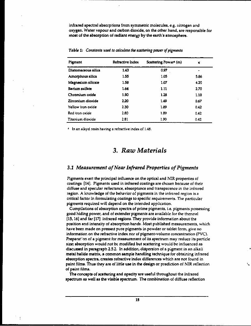
In Equation 8, n is the refractive index of the resin in the paint. Table 1 containsvalues of n, ti and K for common paint pigments dispersed in a n alkyd resinhaving a refractive index of 1.48. In a later study using the Mie scattering theoryit was shown that, to a good approximation, the same relationship may beextended to different wavelengths with correspondingly different optimumparticle sizes [121.
Commercial titanium dioxide pigments are manufactured with a particle size of200 nm, the optimum value for scattering visible radiation with a peak intensityof 500 nm [131. As can be seen in Equations 7 and 8, larger particle sizes will berequired to scatter the longer wavelengths of infrared radiation. For titaniumdioxide and red iron oxide, 1 mm particles would effectively scatter near infraredradiation at 2.3 mm, but for other pigments, larger particle sizes would be neededto scatter light at the same wavelength. To scatter thermal infrared radiation,particles several micrometers in diameter would be required.
2.5.3 Absorption of Radiation
The coefficient of absorption of radiation will, in general, vary with wavelength.When radiation passes through a gas, certain wavelengths are preferentiallyabsorbed. These are the same as those observed in the emission spectrum of thegas. In homogeneous condensed materials, molecular interactions broaden theelectronic states.
Infrared radiation incident upon a paint may cause polarization of the electricaland magnetic (polar) components within the compounds which comprise thepaint. Alignment of permanent dipoles is ineffective at high frequencies (infraredfrequencies) because the movement of dipoles is too slow to follow field variation[4]. The external electric field component reacts with the electric field of the atomor molecule displacing the electrons relative to the nucleus. Spectra observed inthe infrared are mostly due to transitions between the energy levels of moleculesrather than atoms. Strong absorption of infrared radiation occurs only fortransitions between states with different dipole moments. Thus there are no
14
infrared spectral absorptions from symmetric molecules, e.g. zntrogen andoxygen. Water vapour and carbon dioxide, on the other hand, are responsible formost of the absorption of radiant energy by the earth's atmosphere.
Table 1: Constants used to calculate the scattering power of pigments
a In an alkyd resin having a refractive index of 1.48.
3. Raw Materials
3.1 Measurement of Near Infrared Properties of Pigments
Pigments exert the principal influence on the optical and NIR properties ofcoatings [14]. Pigments used in infrared coatings are chosen because of theirdiffuse and specular reflectance, absorptance and transparence in the infraredregion. A knowledge of the behavior of pigments in the infrared region is acritical factor in formulating coatings to specific requirements. The particularpigments required will depend on the intended application.
Compilations of absorption spectra of prime pigments, i.e. pigments possessinggood hiding power, and of extender pigments are available for the thermal[15, 16] and far [17] infrared regions. They provide information about theposition and intensity of absorption bands. Most published measurements, whichhave been made on pressecd pure pigments in powder or tablet form, give noinformation on the refractive index nor of pigment-volume concentration (PVC).Preparat.'on of a pigment for measurement of its spectrum may reduce its particlesize; absorption would not bE modified but scattering would be influenced asdiscussed in paragraph 2.5.2. In addition, dispersion of a pgment in an alkalimetal halide matrix, a common sample handling technique for obtaining infraredabsorption spectra, creates refractive index differences which are not found inpaint films. Thus they are of little use in the design or prediction of NIR reflectionof paint films.
The concepts of scattering and opacity are useful throughout the infraredspectrum as well as the visible spectrum. The combination of diffuse reflection
15
and selective absorption of light by pigments determines the hiding power of thepaint, that is, its ability to screen the substrate from incident light energy.Measurement of scattering of infrared radiation at 2.5 pm is a useful method toevaluate pigment dispersion [181.
Hiding power and reflectance are characteristics of a paint film rather than of apigment. The behaviour of a pure pigment will change when it is incorporatedinto a paint. For example, non-absorbing pigment particles which reflect aspressed powders allow considerable transmission of infrared radiation whenincorporated into paint films at conventional pigment volume concentrations[191.
A representative group of pigments was selected for the present study of theirinfrared properties. In view of the large differences in oil (resin) absorption bypigments in paint films, each pigment was dispersed in a standard resin at thesame percentage of its critical pigment volume concentration (CPVC) [20] ratherthan at a fixed concentration. (The CPVC is the level of pigmentation, i.e PVC,where just sufficient binder is present to fill the voids between the pigmentparticles. Sharp changes in film properties occur at this point.) An approximatevalue for the CPVC, which makes allowance for oil absorption, was calculated byEquation 9 1211
CPVC +SG A ()
in which SGp and SC, represent the specific gravity of the pigment and resin,respectively, and OAp is the oil absorption of the pigment in grams of oil per 100grams of pigment. In order to produce the semi-gloss finish of most camouflagecoatings, the pigments were dispersed in a resin to produce a paint havingPVC/CPVC = 0.5, a value characteristic of semigloss paints 1221 but this valuemay be adjusted depending on the intended application. Total paint solids, i.e.pigment plus binder, were adjusted to 50 percent by volume, and drawdownswith a 125 pm blade produced dry films 75 to 88 pm thick.
A spectrophotometer operating in the visible and infrared regions and equippedwith an integrating sphere was used to measure the diffuse reflectance spectra ofthe dry films over the wavelength range 400-2300 nm. Measurements of diffuseinfrared reflectance are made over highly reflecting white (R,) and highlyabsorbing black (Rb) surfaces. Data obtained with a Cary Model 2300 recordingspectrophotometer for some representative pigments are given in Table 2.
The infrared properties of pigments can also be estimated simply and rapidlyby measuring their infrared reflectance in a narrow NIR band. This technique isuseful and convenient, but gives much less information than measurement of thediffuse reflectance spectrum. An EEL Reflectometer (Evans Electroseleniu ur Ltd.,Essex, U.K.) modified with cadmiam sulfide detectors and Wratten 88A filterswas used for measurements [23]. The sensitivity of this instrument starts fromzero at 730 nm, rises fairly sharply to a peak response at about 770 nm, and thendecreases steadily to zero at about 890 nm [24]. Data from this technique aregiven in Table 3, and compare favorably with the spectrophotometric data inTable 2. Using films 75 to 88 pm thick, the contrast ratio (CRIR) at 800 nm in theinfrared was calculated for each pigment using Equation 10 and s also given inTable 3.
16
Table 2: Diffuse reflectance values (in percent) of paint films applied over white (R,)and black (Rd) backgrounds.b
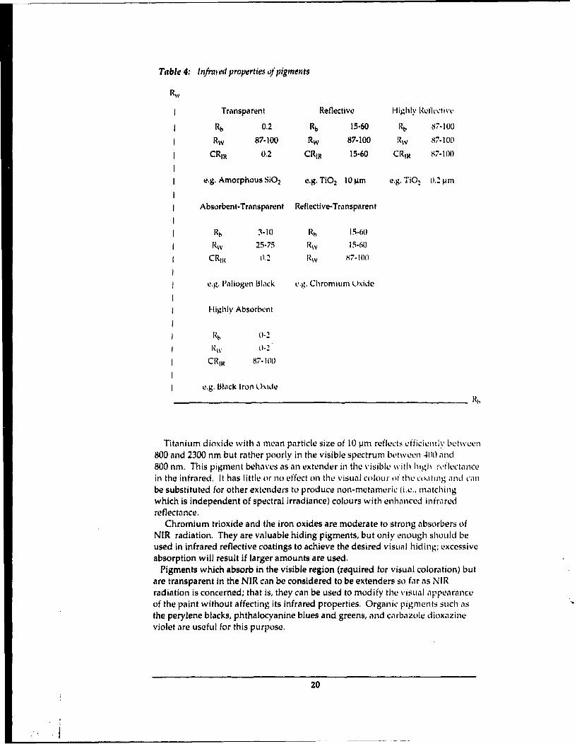
By means of these measurements, each pigment was classified according to itsreflectance and contrast ratio into one of six categories as shown in Table 4. Eachpigment was found to be either highly reflective, highly absorbent, transparent, orintermediate in behavior between any two of these categories. When Rw greatlyexceeds Ri, the pigment is transparent and has little or no hiding power, butsimilar values of Rw and R1 denote high contrast ratios. Values of Rw and RBwhich are similar and high indicate that hiding is principally achieved by diffusereflectance, whereas values which are similar and low indicate that hiding iscaused by absorption; in both of these cases the contrast ratio is high, usuallyabove 0.90.
3.2 Selecting Pigments for Applications in the Near Infrared
A wide variety of useful NIR properties are obtained when pigments aredispersed in films. Titanium dioxide pigments reflect NIR radiation very well, asindicated by their high value of m. Different particle sizes have optimumreflectances in different parts of the spectrum, as shown in Equations 7 and 8.Conventional titanium dioxide with a mean particle size of 200 nm reflects wellbetween 400 and 1700 nm, and is used where reflectance in the visible region ismost important.
e.g. Amorphous SiO 2 e.g. TiO 2 101am e.g. rio, 0.2 pm
Absorbent-Transparent Reflective-Transparent
Ri,3-10 R1 15-60
Rw 25-75 Rw 15-60CR.I 0.2 Rw 87-100)
e.g. Paliogen Black e.g. Chromium Uxide
Highly Absorbent
Rt, 0-2
0-2CRIR 87-100
e.g. Bllack Iron OxideR1,
Titanium dioxide with a mean particle size of 10 pm reflects efficientiv between800 and 2300 nm but rather poorly in the visible spectrum between 400 and800 nrn. This pigment behaves as an extender in the visible with high reflectancein the infrared. It has little or no effect on the visual colour of the coating and canbe substituted for other extenders to produce non-metameric (i.e., matchingwhich is independent of spectral irradiance) colours with enhanced infraredreflectance.
Chromium trioxide and the iron oxides are moderate to strong absorbers ofNMR radiation. They are valuable hiding pigments, but only enough should beused in infrared reflective coatings to achieve the desired visual hiding; excessiveabsorption will result if larger amounts are used.
Pigments which absorb in the visible region (required for visual coloration) butare transparent in the NIR can be considered to be extenders so far as NIRradiation is concerned; that is, they can be used to modify the visual appearanceof the paint without affecting its infrared properties. Organic pigments such asthe perylene blacks, phthalocyanine blues and greens, and carbazole dioxazineviolet are useful for this purpose.
20
Conventional extender pigments such e.s barytes, amorphous anddiatomaceous silica, and talc are transparent and nonreflective throughout thevisible and NIR regions. These pigments are valuable where transparency in theNIR is needed, and they do not interfere with the performance of other pigments.
Carbon black absorbs strongly throughout the NIR and TIR regions 119]. Whenused in small amounts it is effective in decreasing the level of infrared reflectancewithout greatly affecting visible colour. However, should the requiredreflectance of the paint in the NIR or TIR be low, the amount of carbon blacknecessary to bring the reflectance down to this level will have a substantial effecton the visual appearance of the paint.
In addition to spectral factors, conventional coating considerations also play apart in the selection of pigments. These include can-stability, resistance toformation of a friable powder on the surface on exposure (chalking), resistance offlat coatings to polishing to a higher gloss (burnishing), and durability. Inmodern high solids coatings, pigments having the lowest possible product of oilabsorption and specific gravity are valued, as they require less resin and arerelatively free of settling problems.
3.3 Selecting Pigments for Applications in the ThermalInfrared
The technique of using large pigment particles to promote scattering is restrictedin the TIR region. For example, in order to scatter radiation at 12 pm, titaniumdioxide particles 5 pm in diameter are required, and particles of this size, i.e.H-legman 7.5, (the Hegman scale is a measure of the fineness of dispersion of apigment, larger numbers indicating larger particles) are large enough to affect thegloss of a coating. If radiation at 12 pm is to be effectively scattered by a pigmentwith a low value of i, such as talc, a 50 pm-particle would be required. A particle50 pnm in diameter, i.e. Hegman 4, is the largest that could be tolerated; it wouldmake a coating visibly coarse and would affeCL colour uniformity, dirt retention,and other important performance properties [251.
In addition, most inorganic pigments have strong, broad absorption bands inthe TIR region. For example, carbonates absorb near 7 pm, silicates around 9 jim,and oxides between 9 pm and 30 pm. Organic pigments such as the peryleneblacks, phthalocyanine blues and greens, and carbazole dioxazine violet showstrong, sharp absorption bands throughout the TIR region, but principallybetween 6 and II pAm. Thus, properties of coatings will be influenced by thepigments used and will be strongly wavelength dependent, and grey bodyapproximations are likely' to lead to considerable error.
For this reason, metallic pigments, particularly metal flake pigments, arepreferred in the TIR region. They absorb TIR energy poorly, but scatter and reflectefficiently throughout this region. Hagen-Rubens [261 first attributed the highinfrared reflectance of metals as being due to their high density of conductionelectrons. Coatings filled with metallic pigments, particularly leafing pigments,do not demonstrate appreciable wavelength dependence, and so grey-bodyapproximations can be used.
21
3.4 Spectral Properties of Resins
There are two principal requirements for resins in tailored infrared coatings.First, the resin must protect the pigments and preserve their infrared propertiesthroughout the service life of the coating. In addition, the resin must besufficiently transparent in the spectral region of interest.
Most organic resins are free from strong absorptions in the NIR region and canbe used for many applications in this part of the spectrum.
However, in contrast to the characteristics of paints in the visible and NIRregions, paint behaviour in the TIR region is strongly influenced by the resin, andthe performance of the coating is determined by the n,-ture of both the pigmentand the resin. Organic resins show strong absorption bands due to molecularvibrations of their functional groups; bands near 3.3 (C-H stretch), 5.7 (C=Ostretch), 7.0 (C-H bending) and 8.0 mm (C-O stretch) are usually prominent. Acollection [15] of infrared absorption spectra of organic resins is a useful aid inselecting a resin.
Strong absorption in the TIR can be avoided by choosing resins which do notcontain common functional groups. Poly(vinylidene fluoride) resins are almosttransparent to and unaffected by solar radiation, and have only weak absorptionin the TIR region [271. They have excellent weather stability and show greatpromise for tailored infrared coatings. Dimethyl silicone resins have emittancevalues lower than those of fully organic resins and have been used for low-emittance coatings [28]. Inorganic silicate oligomers form polymers whichcontain only silicon-oxygen bonds [291, these resins show low emittance exceptfor a band near 9 gm.
Absorption by resins can also be diminished by the selection of pigments which,because of their refractive indices and particle sizes, scatter light effectively inbands where resins absorb. This technique can be used to great advantage in theTIR region. In addition, leafing metallic pigments which form a practicallycontinuous film reduce the penetration of incident radiation and absorption bythe underlying resin.
4. Formulation
4.1 Preparing for Formulation
Before beginning the formulation of any coating with specified infraredproperties, the illuminants and conditions of illumination, the spectral response ofthe detector or viewer, the desired visual colour of the coating, and the spectraldistribution of the radiation to be reflected or absorbed must be defined. Thenext step is to select a vehicle with good heat resistance and minimal absorptionin the infrared bands of interest. Pigments are then selected and, the refractiveindex of the resin being known, the required particle size distribution iscalculated using Equations 7 and 8. Special attention must be given to bandswhere the resin absorbs strongly and to the regions where reflection of infraredradiation is especially desired.
22
4.2 Control of Colour
The colour of a coating (i.e., its visible reflectance spectrum) is normallyestablished for cosmetic or camouflage requirements, and the opportunity to alterthe amount of visible light reflected or its wavelength distribution is severelyrestricted. Two avenues of approach to colour matching are available. First, apigment which is transparent in the visible region but highly reflective in theinfrared can raise the infrared reflectance without affecting the visible colour, anda nonmetameric match to the desired colour can be made. An example of anappropriate pigment for this is the large particle size titanium dioxide discussedin paragraph 3.2.
Alternatively, pigments employed for visual colour match which absorbstrongly in the infrared can be removed and replaced with pigments which showsimilar absorptions in the visible but reflect or are transparent in the infrared.This is seldom a simple matter, and additional pigments will have to be added toduplicate the desired colour. As an example, carbon black can be replaced by anorganic perylene black such as Paliogen Black [301 or Heliogen Black [31]. Whenused as tints, the former has a green shade and the latter has a violet shade. Acolorant such as red or yellow iron oxide, respectively, must be added to re-estr blish a true black or grey shade. The colour thus produced will be metamericto the original colour, and the old and new colours may not match under all typesof illumination or observation.
Where reflectance is important, the amount of hiding pigments which absorb.should be just sufficient to meet the requirements for hiding. The balance of thepigmentation should be made up of extender pigments with optimized infraredreflectance.
4.3 Control of Emissivity in the Thermal Infrared
The emissivity of a coating contributes directly to its signature in the TIR region,and emissivity as well as reflectance must be controlled in order to achieve theperformance desired. Organic resins are strong emitters in the thermal infraredregion, particularly at the wavelengths which are found in their absorptionspectra. Oxide, carbonate, and silicate pigments show selective emission; forexample, titanium dioxide emits near 8 Am.
Finely dispersed metallic pigments such as aluminum flake have low emissivityand are used to decrease the emissivity of organic coatings. Bright aluminum foilhas a reflectance of about 95 percent for black body radiation from a source at50*C; the maximum energy from such a source is emitted at 9 Am. Aluminumpaints show reflectivity as high as 82 percent and emissivity as low as 18 percent[32].
Clean or polished metallic substrates radiate heat poorly, but their emissivitycan be enhanced by a wide range of black or dark oxide, phosphate, chromi'teand other coatings applied by chemical or electrochemical processes [33]. Whencooling of a coated object is important, high emissivity coatings are used. On tileother hand, coatings with low emissivity are used to retain heat within, forexample, steam pipes or boilers.
23
5. Coatings with Tailored Infrared Reflectance
5.1 Low NIR or Low TIR Signature?
Defence equipment used by Australian and overseas forces is painted in a rangeof schemes which are designed to absorb and/or reflect in the infrared region. Inpart, selection of the infrared characteristics is determined by the operational roleof the equipment. The Australian Army's Disruptive Pattern Paint scheme usedfor camouflage employs three paints which have relatively low NIR reflectingvalues, each differing from the other to create a disruptive pattern in the NIR aswell as in the visible. This scheme is designed to protect against systems(considered to be major threats) which use the NIR waveband and operate in lowlight conditions.
The painting practices for military aircraft suggest that the detection threat hasnot been clearly identified for the environmental conditions in which theyoperate. Where solar radiation is low, as in a number of NATO countries, solarheating and the consequent increase in TIR signature will be of little importance.However, in subtropical and tropical countries, low NIR reflecting paints result inexcessive heat loads and significantly higher TIR signatures, particularly in the 8to 14 pm region. As the threat to aircraft by NIR photographic detection isminimal and there are no anti-aircraft missiles using the NIR waveband, theadvantage provided by these paints would seem to be outweighed by theirdisadvantages.
A number of military aircraft are painted in highly reflecting NIR paints andothers in highly absorbing NIR paints. However, some local and overseas militaryaircraft are painted with highly absorbing NIR primers but employ highlyreflecting NIR topcoats, a practice that is counterproductive. An understandingis required that the term low infrared reflecting paint generally means a paint thatis highly absorbing in the NIR (with a consequently higher TIR signature onexposure to sunlight). Likewise, the term high infrared reflecting paint refers tohighly reflecting NIR paint (with a consequently lower TIR signature on exposureto sunlight).
5.2 Solar Heat (near infrared) Reflecting Coatings
Coatings formulated to reflect a high proportion of solar radiation lower theabsorption of solar energy and the consequent temperature of the surface.
Absorptance in the ultraviolet region contributes little to the total energyabsorbed by a coating, and it is usually not profitable to direct attention to thisportion of the spectrum. The visible reflectance of a coating is established; slightadjustments as discussed in paragraph 4.2 may be made if metamerism can betolerated, but significant modification of absorption in the visible region isunlikely to be allowed owing to established convictions of visible camouflagerequirements. Thus, the most effective way to produce a solar heat reflectingcoating is to maximize the reflectance of solar energy in the near infrared regionof the spectrum.
24
Solar reflective coatings have been formulated in either of two ways. In the firstcase, it is possible to produce solar reflective coating systems comprising a highlyreflective undercoat and a topcoat which can be coloured with pigmentstransparent to NIR radiation. The topcoat provides the desired visual colour butdoes not absorb NIR radiation. The topcoat must be as thin as possible for it willalways possess some absorption. Also, for uniform visual appearance the filmthickness has to be consistent; this is not always easy when the coating is appliedoutside a factory. Maintenance is a problem because topcoat and undercoat mustbe applied at proper thicknesses and intercoat intervals to retain properties, andthe cost of a two coat system exceeds that of a single coat.
In so far as visible colour permits, pigments which strongly absorb in theinfrared should be avoided in the topcoat of a two coat system. As the nearinfrared absorptance of the topcoat increases, reflectance from the undercoat isdiminished because less energy reaches the undercoat. It is essential to payparticular attention to pigment volume concentration in the topcoat under theseconditions.
A preferred solution is to use pigments which are reflective in the NIR toproduce a single coating. Blending reflective and transparent pigments givesmuch flexibility in tailoring infrared properties, and the difficulties of a two-coatsystem are avoided.
These coatings are designed to reduce thermal emission and to reflect incidentTIR radiation. Metallic pigments, particularly aluminium flakes, reflect stronglyacross the TIR region and are the principal active ingredient in these coatings.The best aluminium paints for this purpose are those made with extra brilliantgrades of aluminium flake which have larger particle sizes. Pigments whichoverlap in a systematic manner, known as leafing pigments, have been shown toproduce greater reflectance than nonleafing pigments [32], and this has beenascribed to the complete hiding of the resin by the leafing metal flakes in thematrix. Aluminium paints reflect thermal infrared with greater efficiency thanthey reflect white light. Black coatings are commercially available [34) which offerlow solar reflectance and high thermal reflectance (0.9), i.e. thermal emissivities of0.1. It is understood that these materials have been trialled on NATO tanks,however the high solar collection efficiency of this material would require that itsuse in tropical and subtropical environments be closely engineered.
Table 5 shows the temperature transfer properties of a steel panel coated on theilluminated side with the standard Australian Navy grey paint compared to onepainted on the illuminated side with a leafing aluminium paint.
5.4 Camouflage Coatings
Camouflage coatings adjust the normal reflectance of an object so that itresembles its immediate environment, thus making it nearly indistinguishablefrom its surroundings under natural as well as artificial illumination. Camouflagecoatings must reflect both visible light and infrared radiation to the same degreeas their surroundings. For terrestrial applications, the most importantenvironments where concealment is desired are foliage and desert regions.
25
Table 5: Effect of paint composition on thermal emission
Temperature Rise (MC) a
Time (minutes) Sides I and 2 Side 1aluminium paintc
Std Australian Navy grey paintb Side 2Std Australian Navy grey paint
a Panels at room temperature (200C) at time 0.b Both sides painted with grey paint.c Irradiated side painted with aluminium paint, reverse side painted with grey paint.
Pattern painting with various camouflage colours can also break up thesilhouette of an object and make it less conspicuous. For maximum effectiveness,the various coatings used in the pattern must be significantly different in bothoptical and infrared reflectance [351. Coatings having low emissivity are used tominimize temperature contrasts between vehicles exposed to solar radiation andtheir surroundings. They are most effective when the emissivity varies betweenpatches of paint and the infrared outline of the vehicle is masked.
5.4.1 Coatingsfor Forest and Jungle Areas
Pigments used to produce green coatings for these areas are selected for theirability to duplicate the reflectance properties of chlorophyll, the green pigmentresponsible for the characteristic colour and high infrared reflectance ofvegetation. The reflectance spectrum of chlorophyll shows a peak near 550 nm,low values in tho. visible red region, a dip in the far visible red at 650-680 nm, asharp rise between 680 and 710 nm, and uniformly high values above 720 nm.The goal for woodland camouflage coatings is to match this spectrum. Coatingsfor camouflage must control reflectance in the NIR between 700 and 1200 nm; theband between 700 and 900 run is most important (36).
26
Most specifications for camouflage coatings require a sharp rise in reflectancebetween 700 and 720 nm, and require that the average reflectance in the 700 to900 nm region exceeds the average reflectance in the 600 to 690 nrn region. Suchcoatings approximate the reflectance spectrum of chlorophyll and appear in theNIR to have the same reflectance as natural vegetation.
Many green pigments resemble the colour of chlorophyll but, unlikechlorophyll, show strong absorption in the NIR. Chromium trioxide is green incolour and possesses a reflectance curve similar to that of chlorophyll, and wasthe principal pigment in early NIR camouflage paints. For some specificationswhich do not call for reflectance to rise rapidly in the NIR, chromium trioxidetinted to the desired visual shade can still be used as the basic pigment. Wheninfrared photography or modern detection methods are used, however, thesepigments are readily detected as dark shadows against a light background ofnatural vegetation.
Older formulations based on lead chromate (chrome yellow), basic leadchromate (chrome orange) and molybdated lead chromate (moly orange), andtinted with blue and red pigments, produce camouflage coatings in a variety ofgreen shades 1371, but their use has been curtailed in the United States because oftheir extremely high lead conteni.
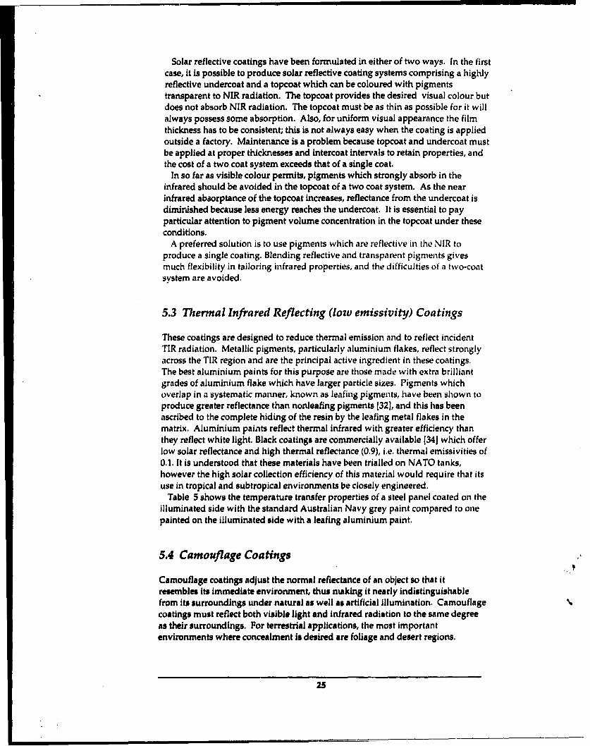
A range of visual colours is used for modern camouflage coatings. Each colouris specified by its brightness Y and its chromaticity coordinates x and v. Theseparameters are defined by the International Commission on Illumination, knownas CIE from its name in French, Commission Internationale d'Eclairage. Thedesired colour is plotted as a point on a chromaticity diagram, and colourtolerance is stipulated by a boundary on which lie all points which differ from thetarget colour by the same visual difference. The boundary normally takes theform of an ellipse, as shown in Figure 3 for US forest green camouflage paint 1381.In this case the visual difference is stipulated by the obsolescent N3IS [for (US)National Bureau of Standards] unit, which is computed using complex equationsfrom the Y, x and y values of the standard and sample colours 139).
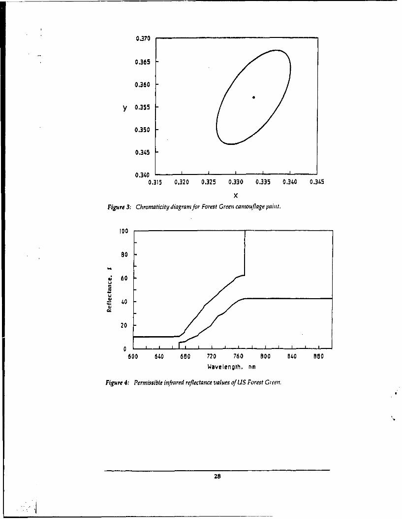
Infrared reflectance is specified in various ways. British Material SpecificationDTD 5618 1401 stipulates minimum values of reflectance at 700, 800, 900, 1000,1400 and 2000 nm for each of eleven colours. In the United States, the infraredreflectance is specified by a narrow range of permissible values as shown inFigure 4. Chromium oxide alone cannot meet this requirement. Cobalt chromitespinels containing small amounts of zinc and titanium are the most effectivepigments for this purpose and are tinted to the desired spectral properties withiron and chromium oxides and organic yellows, browns and violets. The opticalbrightness (Y), the average reflectivity in the 600 to 900 nm band, and thereflectivity ratio of the band at 700 to 900 nm to the band at 600 to 690 omi are alsospecified for forest green camouflage paint (391.
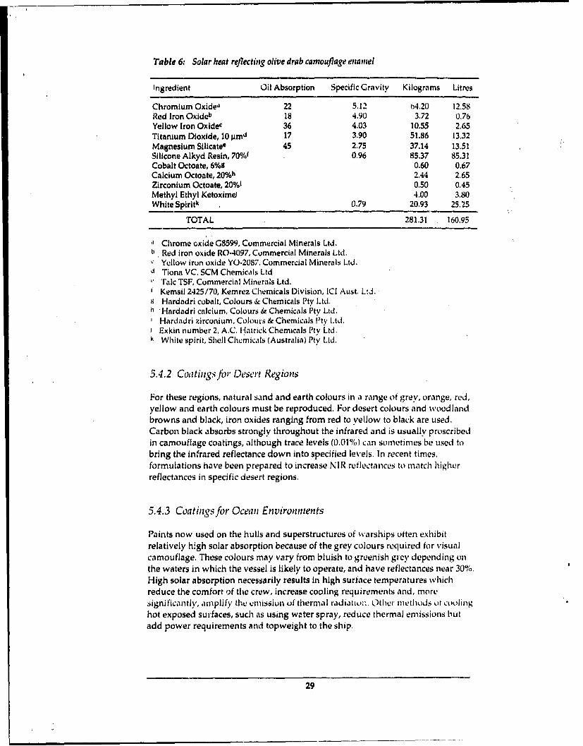
A solar heat reflecting lusterless olive drab enamel conforming to AustralianSpecification 7650/ADF(M) 146-1 [41] has been produced in the present studyfrom some of the pigments in Table 4. This coating has a reflectivity of 42% at800 nm and a gloss of I. The formulation of this coating is given in Table 6.
27
0.370
0.365
0.360
y 0.355
0.350 -
0.345
0.340 I I I0.315 0,320 0.325 0.330 0.335 0.340 0.345
x
Figure 3: Chromaticity diagram for Forest Green camouflage paint.
00
80
4; 60
S40
20
600 640 680 720 760 800 840 880Wavelength, nm
Figure 4: Permissible infrared reflectance values of US Forest Green,
28
---_ ,, -______________________________________
Table 6: Solar heat reflecting olive drab camouflage enamel
Ingredient Oil Absorption Specific Gravity Kilograms Litres
Hardadri zirconium, Colours & Chemicals Ptv Ltd.Exkin number 2, A.C. Hatrick Chemicals Pty Ltd.
k White spirit, Shell Chemicals (Australia) Pty Ltd.
5.4.2 Coatings ftr Desert Regions
For these regions, natural sand and earth colours in a range of grey, orange, red,yellow and earth colours must be reproduced. For desert colours and woodlandbrowns and black, iron oxides ranging from red to yellow to black are used.Carbon black absorbs strongly throughout the infrared and is usually proscribedin camouflage coatings, although trace levels (0.01%) can sometimes be used tobring the infrared reflectance down into specified levels. In recent times,formulations have been prepared to increase NIR reflectances to match higherreflectances in specific desert regions.
5.4.3 Coatings for Ocean Environments
Paints now used on the hulls and superstructures of warships often exhibitrelatively high solar absorption because of the grey colours required for visualcamouflage. These colours may vary from bluish to greenish gr'ey depending onthe waters in which the vessel is likely to operate, and have reflectances near 30%,High solar absorption necessarily results in high surface temperatures whichreduce the comfort of the crew, increase cooling requirements and, moresignificantly, amplify the emission of thermal radiat|ion. Oth1Ce methods Of coolinghot exposed surfaces, such as using weter spray, reduce thermal emissions butadd power requirements and topweight to the ship.
29
Most of the common blue and black pigments absorb infrared radiationstrongly, and even small amounts are effective in reducing infrared reflectance.Historically, naval coatings have contained significant amounts of carbon black(42,43]. An early attempt [441 to formulate without carbon black produced solarheat reflecting coatings and low emittance coatings containing 15% of powderedaluminium [45,46]. These coatings had poor weatherability and colour retentionbecause antimony sulfide, a black pigment used in place of carbon black, isunstable and reacts with air to form white antimony oxide on prolongedexposure.
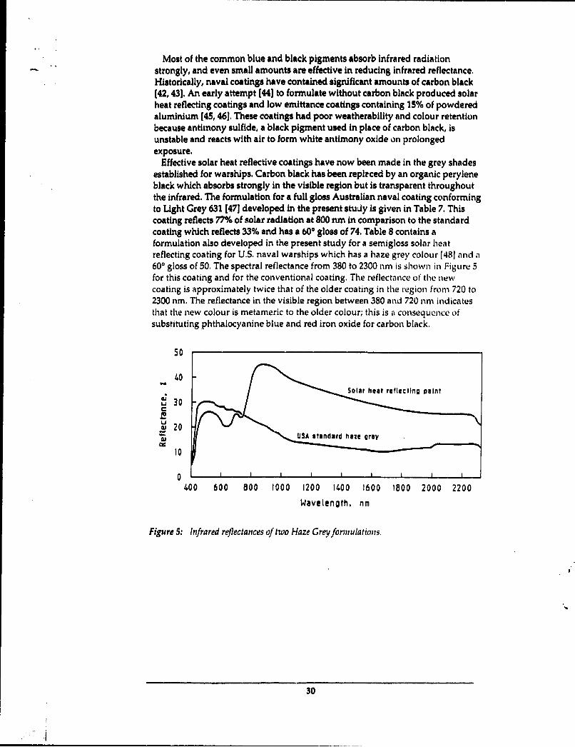
Effective solar heat reflective coatings have now been made in the grey shadesestablished for warships. Carbon black has been repleced by an organic peryleneblack which absorbs strongly in the visible region but is transparent throughoutthe infrared. The formulation for a full gloss Australian naval coating conformingto Light Grey 631 [471 developed in the present stuiy is given in Table 7. Thiscoating reflects 77% of solar radiation at 800 nm in comparison to the standardcoating which reflects 33% and has a 600 gloss of 74. Table 8 contains aformulation also developed in the present study for a semigloss solar heatreflecting coating for U.S. naval warships which has a haze grey colour [481 and a600 gloss of 50. The spectral reflectance from 380 to 2300 nm is shown in Figure 5for this coating and for the conventional coating. The reflectance of the newcoating is approximately twice that of the older coating in the region from 720 to2300 nm. The reflectance in the visible region between 380 and 720 nrn indicatesthat the new colour is metameric to the older colour; this is a consequence ofsubstituting phthalocyanine blue and red iron oxide for carbon black.
Hardadri zirconium, Colours & Chemicals Ptv Ltd.i I"xkin number 2, A.C. Hatrick Chemicals Pty Ltd.k White spirit, Shell Chemicals (Australia) Pty Ltd.
5.4.4 Coatings for aircraft
Strict courtershading principles are used by the U.S. Navy on maritimereconnaissance aircraft which involve the darkest colour on top, intermediate onthe sides and :ightest shade underneath. This system is used as detection fromabove will involve the aircraft against a sea background which has a reflectancefactor to sunlight of less than 3% [49]. Viewed against a clear sky, the relativeeffect of paint schemes is related to the direction of view to the sun. White aircraftappear lighter than the sky when viewed down sun so light grey colours areemployed. The thermal load from insolation into the P3-C aircraft painted withthe U.S. Navy grey paint (which is a low infrared reflecting paint) has beendetermined to be 1.7 kW more than that for the same aircraft with white top halffuselage and all other surfaces grey which is the RAAF 1990 colour scheme [50].The air temperature for this comparison was 330C. The infrared reflectances ofthe high NIR reflecting paints were compared to those of standard paints of thesame visual colours and are shown in Table 9. In theory, these grey coloursshould reduce the heat load by 50% compared to painting in standard greycolours.
31
Table 8: Solar heat reflecting Haze Gray camouflage enamel
Ingredient Oil Specific Kilograms LitresAbsorption Gravity
k Exkin number 2, A.C. Hatrick Chemicals Pty Ltd.White spirit, Shell Chemicals (Australia) Pty Ltd.
Table 9: NIR reflectances of standard paints and solar reflecting paints for Orioncamouflage paint scheme
Y Standard Paint NIR Reflecting Paint
49.5 52% 77%
37.5 43% 70%23.5 24% 61%
32
6. SummaryRelevant physical laws governing the response of coatings to solar and infraredradiation have been reviewed. The reflection of infrared radiation by a paint iscontrolled primarily by the refractive index and particle size of the pigments inthe coating. Pigments have been evaluated for reflectance, transparence andhiding power in the near infrared region, and guidelines for pigment slection forvarious applications given in terms of their optical properties in the near infraredregion. Raw materials selection, manufacture and evaluation of coatings havebeen discussed with respect to tailoring infrared reflectance. By employing theprinciples developed herein and using pigments with appropriate properties,organic coatings have been developed which are consistent with the visible colourrequirements of the Australian and US Navies. Significant increases in thereflection of infrared radiation have been demonstrated by the new formulations.The need for a very clear understanding of the threat systems and the operationalconditions of service platforms has been emphasised. It is only with thisunderstanding that optimum paint schemes can be devised. However, it can bestated that the use of the solar infrared reflecting paints described herein wouldreduce conspicuity of isolated platforms to surveillance and seeker systemsoperating in the mid and far infrared without detriment to visual camouflagecharacteristics.
7. References
I. Ogorkiewicz, R.M. (1989), lIternational Defese Review, 22 (1) 53.
2. Gray, D.E. (Ed.) (1972). American Instit ute of PhIsics i-ihdbook, 3rd ed.pp. 6-7. New York: McGraw-Hill Book Company, Inc.
3. Wolfe, W. and Zissis, G.J. (1978). The lifrared Handbook. Office of NavalResearch, Washington, DC.
10. Brady, R.F. Jr., Griffith, J.R., Love, KS. and Field, D.E. (1989) in Polymers in"a Marine Environment. The Institute of Marine Engineers, London, Paper 26,p. 19 1 .
11. Jaenicke, W. (1956). Zeitschiftfur Elektrochemische, 60, 163.
12. Tomkins, L.M. and Tomkins, E.H. (1958). Journal of the Oil and ColourChemists Association, 41, 98,
13. Stamatakls, P., Palmer, B.R., Bohren, C.F., Salzrnan, G.C. and Allen, T.B.(1990). Journal of Coatings Technology, 62 (789) 95.
14. Wake, L.V. (1990). Journal of the Oil and Colour Chemists Association, 73 (2)78.
15. An Infrared Spectroscopy Atlas for the Coatings Industry (1980). Federation ofSocieties for Coatings Technology, Blue Bell, PA.
21. Hare, C.H. (1990). Journal of Protective Coatings and Lihimgs, 7 (7) 47.
22. Patton, T.C. (1979). Paint Flow and Pigment Dispersion, 2nd ed., chapter 7.New York: John Wiley & Sons.
23. Marson, F. (1968). A Simple Method for the Measuremen t of i'fraredReflectance of Paints (MRL Technical Note 110). Maribyrnong, Vic.:Materials Research Laboratory.
24. Marson, F. (1982). A Low Cost, Simple, Portable Instrument for theMeasurement of Infrared Reflectance of Paints (MRL Report MRL-R-857),Maribyrnong, Vic.: Materials Research Laboratory.
25. Sward, G.G. and Jacobsen, A.E. (1972).. Paint Testing Mamal, 13th Ed.,G. G. Sward, Ed. Special Technical Publication 500, A. Soc. Test. Mater.,Philadelphia, PA, p. 218.
26. Hagen, E. and Rubens, H. (1904). Annalen. de Chimique Physique, 2, 441.
28. Mar, H.Y.B. and Zimmer, P.B. (to the United States of America),
U. S. Patent 4,131,593, December 26, 1978.
29. Brady, R.F. Jr., (1987). Journal of Protective Coatings and Linings, 4 (7) 42.
30. Paliogen Black: A product of BASF.
31. I-Teliogen Black: A product of Bayer.
32. Edwards, J.D. and Wray, R.I. (1955). Aluminum Paint and Powder, 3rd Ed.New York: Reinhold Publishing Corporation.
33. Brady, R.F. Jr., Lasser, H.G. and Pearlstein, F. (1985). Materials andProcesses, 3rd Ed., p. 1267, R. S. Shane and R. Young, (Eds.), New York:Marcel Dekker, Inc.
34. Maxorb. Surface Treated Nickel Foil. A product of INCO Alloys Int.
35. Pusch, G. British Patent 1,605,131, December 16, 1981.
40. British Aerospace Material Specification DTD 5618, Exterior and InteriorFinishing Schemes - Matt and Glossy - Solar Heat Reflecting (Cold CuringPolyurethane Type). HMSO, London, October, 1974.
41. Lustreless olive drab is contained in Australian Specification 7650/ADE(M),dated November 1967. The CIE c hromaticity coordinates are x = 0.351 andy = 0,367 and the optical brightness Y is 11.0.
44. Supcoe, Coatingsfor Infrared Camouflage. Report C-3946, David TaylorResearch Center, Annapolis MD, July 1974.
45. Supcoe & M. Greenberg (to the United States of America), U.S. Patent4,289,677, Sep 15 1981.
35
46. Siapcoe (to the United States of America),. U.S. Patent 4,311,623, January 19,"1982.
47. Light Grey 631 is contained in Coloursfor Specific Purposes, Br. Standard 381C,1964. The CIE chromaticity coordinates are x = 0.302 and y = 0.325, and theoptical brightness Y is 29.2. The approximate Munsell reference colour is7.5G 6/1.
48. Haze Gray color 26270. Colors, Federal Color Standard 595A, January 1968.The CIE chromaticity coordinates are x = 0.298 and y = 0.307, and theoptical brightness Y = 25.6.
49. Beckwith, P.J. and Boyd, R.J. (1988). Visibility of P3-C Orion Aircraft(MRL Report MRL-R-1103). Maribyrnong, Vic.: Materials ResearchLaboratory.
50. Report of Test Results No. AT-8R-83, Naval Air Test Center, Maryland 20670,March 1983. Cited in Reference 49.
36
SECURITY CLASSIFICATION OF THIS PAGE UNCLASSIFIED
REPORT NO. AR NO, REPORT SECURITY CLASSIFICATIONM RL-RR-1-93 AR-008-254 Unclassified
TITLE
Formulating infrared coatings for defence applications
AUTHOR(S) CORPORATE AUTHORLV. Wake and R.F. Brady DSTO Materials Research Laboratory
PO Box 50Ascot Vale Victoria 3032
R1E PORT DATE TASK NO. SPONSOR
March, 1993 91/141
FILE NO. REFERENCES PAGESG6/4/8-4222 50 37
ClI.ASSII'ICATION/I.IMITATION REVIEW DATE CLASSIFICATION/ RELEASE AUTHORITY
SECONDARY DISTRIBUTION
Approved for public release
ANNOUNCEMENT
Announcement of this report is unlimited
K EYWORDS IIs
Emissivit\, Absorption Coating systemsThermal infrared Near infrared PaintsReflecta nce
ABSTRACT
Relevant physical laws governing the response of coatings to solar and infrared radiation have been reviewed.The reflection of infrared radiation by a paint is controlled primarily by the refractive index and particle size ofthe pigments in the coating. Pigments have been evaluated for reflectance, transparence and hiding power ilithe near infrared region, and guidelines for pigment selection for various applications given in terms of theiroptical properties in the near infrared region. Raw materials selection, manufacture and evaluation of coatingshave been discussed with respect to tailoring infrared reflectance. By employing the principles developed hereinand using pigments with appropriate properties, organic coatings have been developed which are consistentwith the visible colour requirements of the Australian and US Navies. Significant increases in the reflection ofinfrared radiation have been demonstrated by the new formulations. The need for a very clear understandingof the threat systems and the operational conditions of service platforms has been emphasised. It is only withthis understanding that optimum paint schemes can be devised. However, it can be stated that the use of thesolar infrared reflecting paints described herein would reduce conspicuity of isolated platforms to surveillanceand seeker systems operating in the mid and far infrared without detriment to visual camouflage characteristics.
SECURIrY CLASSIFICATION OF THIS PACE
UNCLASSIFIED
Formulating Infrared Coatings for Defence Applications
L.V. Wake and R.F. Brady
(MRL-RR-1-93)
DISTRIBUTION LIST
Director, MRLChief, Protective Chemistry DivisionDr D.B. PaulDr L.V. WakeDr R.F. BradyMRL Information Service
Chief Defence Scientist (for CDS, FASSP, ASSCM) (1 copy only)Director, Surveillance Research LaboratoryDirector (for Library), Aeronautical Research LaboratoryDirector, Electronics Research LaboratoryI-lead, Information Centre, Defence Intelligence OrganisationOIC Technical Reports Centre, Defence Central LibraryOfficer in Charge, Document Exchange Centre (8 copies)Army Scientific Adviser, Russell OfficesAir Force Scientific Adviser, Russell OfficesNaivy Scientific Adviser, Russell Offices - data sheet onlyScientific Adviser, Defence CentralDirector-General Force Development (Land)Senior Librarian, Main Library DSTOSLibrarian, MRL Sydney - data sheet onlyLibrarian, H BlockUK/USA/CAN ABCA Armies Standardisation Rep. c/- DGAT (8 copies)Librarian, Australian Defence Force AcademyCounsellor, Defence Science, Embassy of Australia - data sheet onlyCounsellor, Defence Science, Australian High Commission - data sheet onlyScientific Adviser to DSTC, C/- Defence Adviser - data sheet onlyScientific Adviser to MRDC, C/- Defence Attache - data sheet onlyHead of Staff, British Defence Research and Supply Staff (Australia)NASA Senior Scientific Representative in AustraliaINSPEC: Acquisitions Section Institution of Electrical EngineersHead Librarian, Australian Nuclear Science and Technology OrganisationSenior Librarian, Hargrave Library, Monash UniversityLibrary - Exchange Desk, National Institute of Standards and Technology, USExchange Section, British Library Document Supply CentreLibrary, Chemical Abstracts Reference ServiceEngineering Societies Library, USDocuments Librarian, The Center for Research Libraries, US
Commanding Officer, DWOSU, RAAF Base Edinburgh, SADirector Air Warfare, Russell Offices, Canberra ACTOwen Scott, Electronics Research Laboratory, Salisbury SA


![Romanism & the Reformers [1915] - Sample, R.F.](https://static.documents.pub/doc/80x56/577cdda71a28ab9e78ad7b32/romanism-the-reformers-1915-sample-rf-pdf.jpg)


![[L.v. Tarasov] Calculus - Basic Concepts for High](https://static.documents.pub/doc/80x56/54652b9ab4af9f3f3f8b4e3b/lv-tarasov-calculus-basic-concepts-for-high.jpg)