page 1 of 16 pages SPS-TD-LVA-e-0007.docx LVA series of 4-Quadrant amplifiers AUTOMOTIVE SUPPLY SIMULATION AT IT’S BEST LVA 1000 Front panel Extremely low harmonic distortion - even under very non-linear load conditions Very fast slew rate > 20V/µs Operates from DC up to 50kHz large signal bandwidth (-3dB) Small signal bandwidth up to 300kHz High short-term overload characteristic (for 30s) Very high peak-load ability (up to 200ms) Programmable internal resistance 0 … 200 mSink operation mode included – real 4-quadrant operation mode to be disabled through the touch panel menu Unsymmetric or symmetric voltage ranges Touch panel operation 7” 800x480 The relating standards: ISO 7637-2 ISO 16750-2 ISO 21848 LV 124 VDA 320 (LV 148) SAE J 1113-11 BMW GS 95002 BMW GS 95003-2 BMW GS 95024-2-2 BMW GS 95026 Ford FMC 1278 General Motors GMW 3097 JLR-EMC-CSv1.04A Mercedes-Benz LV 124-1 Mercedes-Benz LV 148 MIL-STD-461F MIL-STD-704F MIL-STD-1275E Mitsubishi ES-X82115 Nissan 28400NDS02_3 PSA B21 7110 Renault 36-00-808/--M VW 80000 VW 82148 VW TL 81000 THE REFERENCE SOURCE FOR AUTOMOTIVE APPLICATIONS PERFECT FOR MANY AVIONIC AND MILITARY STANDARDS
Transcript
page 1 of 16 pages SPS-TD-LVA-e-0007.docx
LVA series of 4-Quadrant amplifiers
AUTOMOTIVE SUPPLY SIMULATION AT IT’S BEST
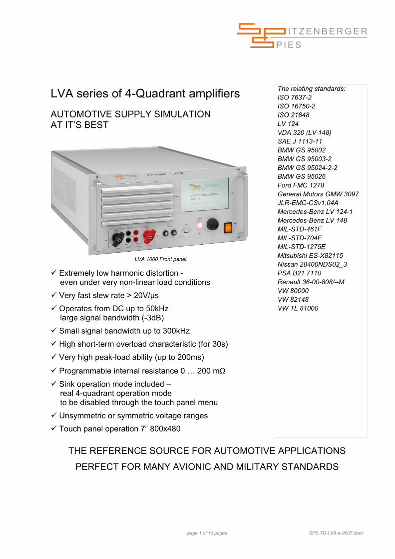
LVA 1000 Front panel
Extremely low harmonic distortion - even under very non-linear load conditions
Very fast slew rate > 20V/µs
Operates from DC up to 50kHz large signal bandwidth (-3dB)
Small signal bandwidth up to 300kHz
High short-term overload characteristic (for 30s)
Very high peak-load ability (up to 200ms)
Programmable internal resistance 0 … 200 m
Sink operation mode included – real 4-quadrant operation mode to be disabled through the touch panel menu
Unsymmetric or symmetric voltage ranges
Touch panel operation 7” 800x480
The relating standards: ISO 7637-2 ISO 16750-2 ISO 21848 LV 124 VDA 320 (LV 148) SAE J 1113-11 BMW GS 95002 BMW GS 95003-2 BMW GS 95024-2-2 BMW GS 95026 Ford FMC 1278 General Motors GMW 3097 JLR-EMC-CSv1.04A Mercedes-Benz LV 124-1 Mercedes-Benz LV 148 MIL-STD-461F MIL-STD-704F MIL-STD-1275E Mitsubishi ES-X82115 Nissan 28400NDS02_3 PSA B21 7110 Renault 36-00-808/--M VW 80000 VW 82148 VW TL 81000
THE REFERENCE SOURCE FOR AUTOMOTIVE APPLICATIONS
PERFECT FOR MANY AVIONIC AND MILITARY STANDARDS
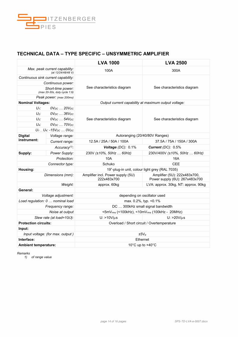
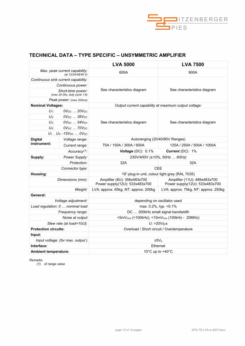
page 2 of 16 pages SPS-TD-LVA-e-0007.docx
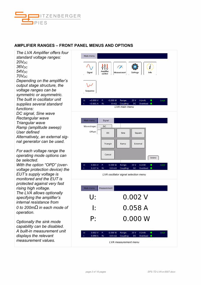
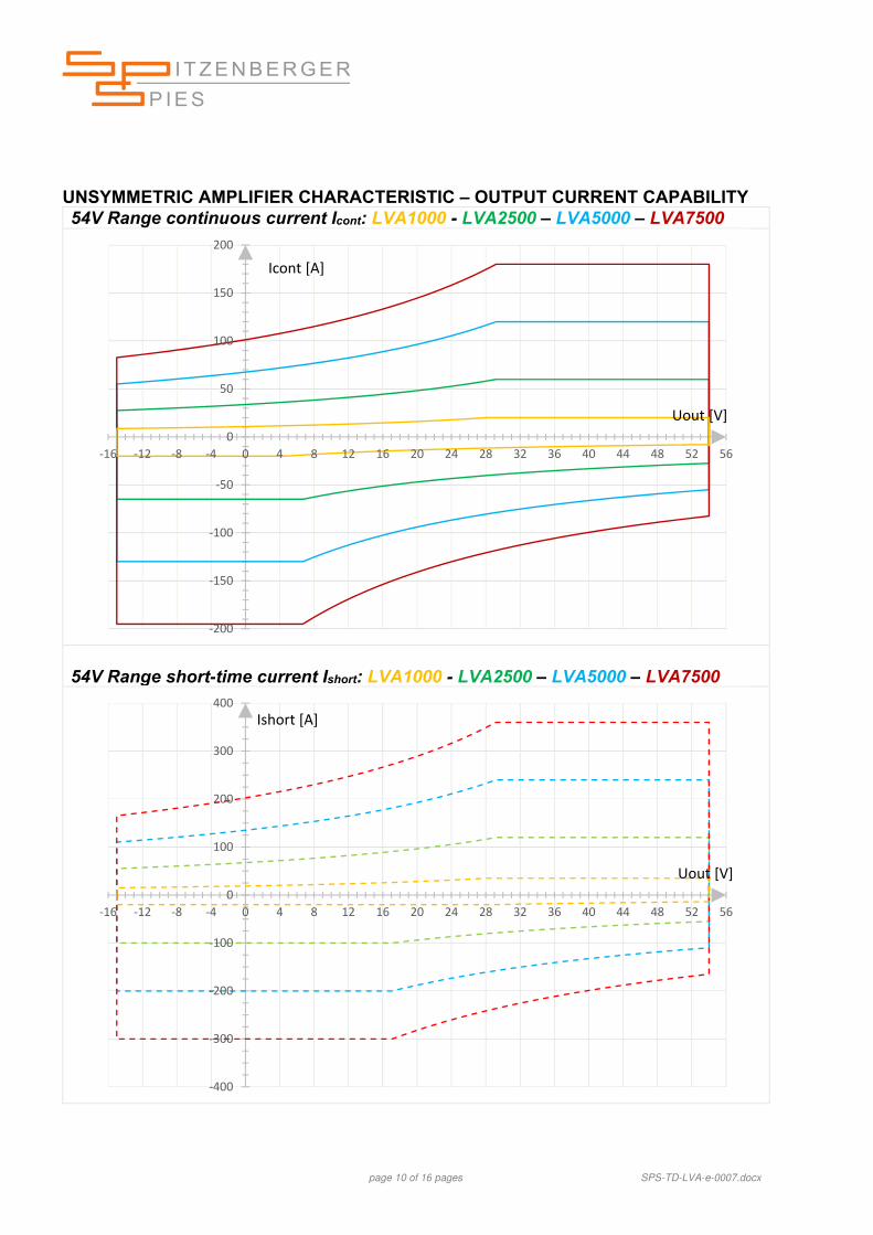
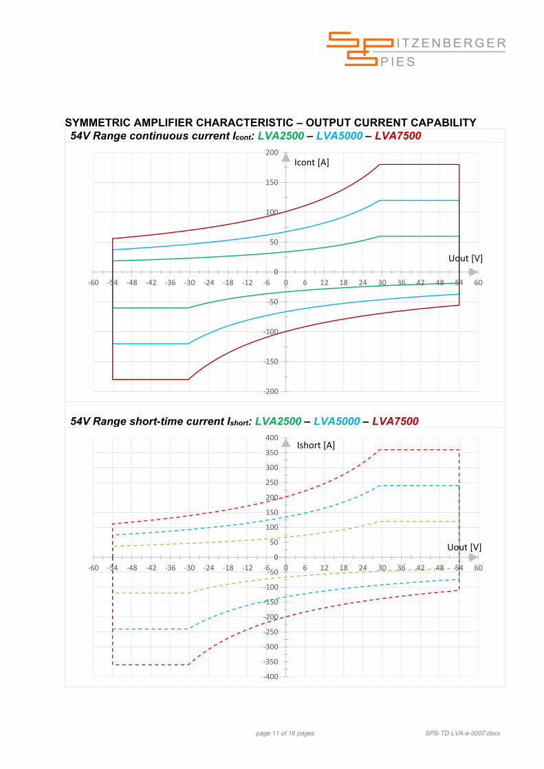
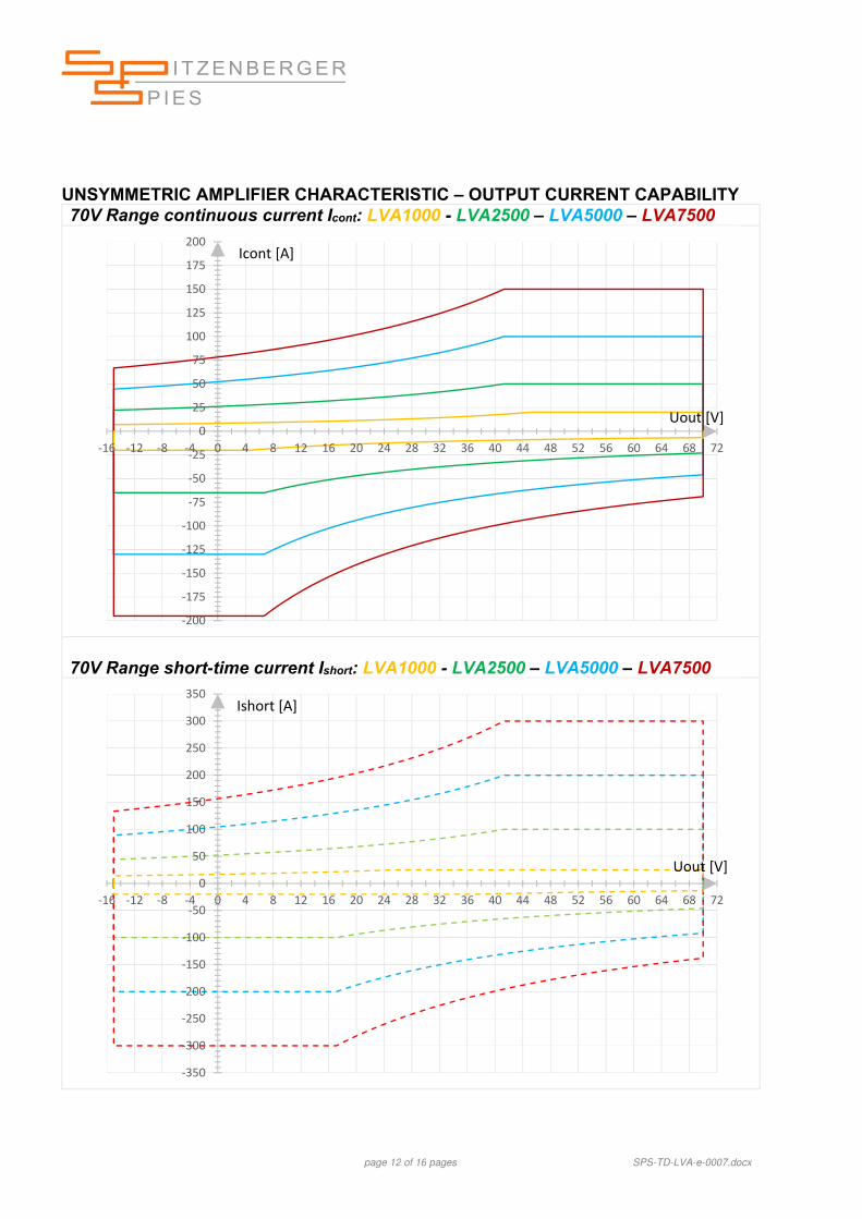
AMPLIFIER RANGES – FRONT PANEL MENUS AND OPTIONS
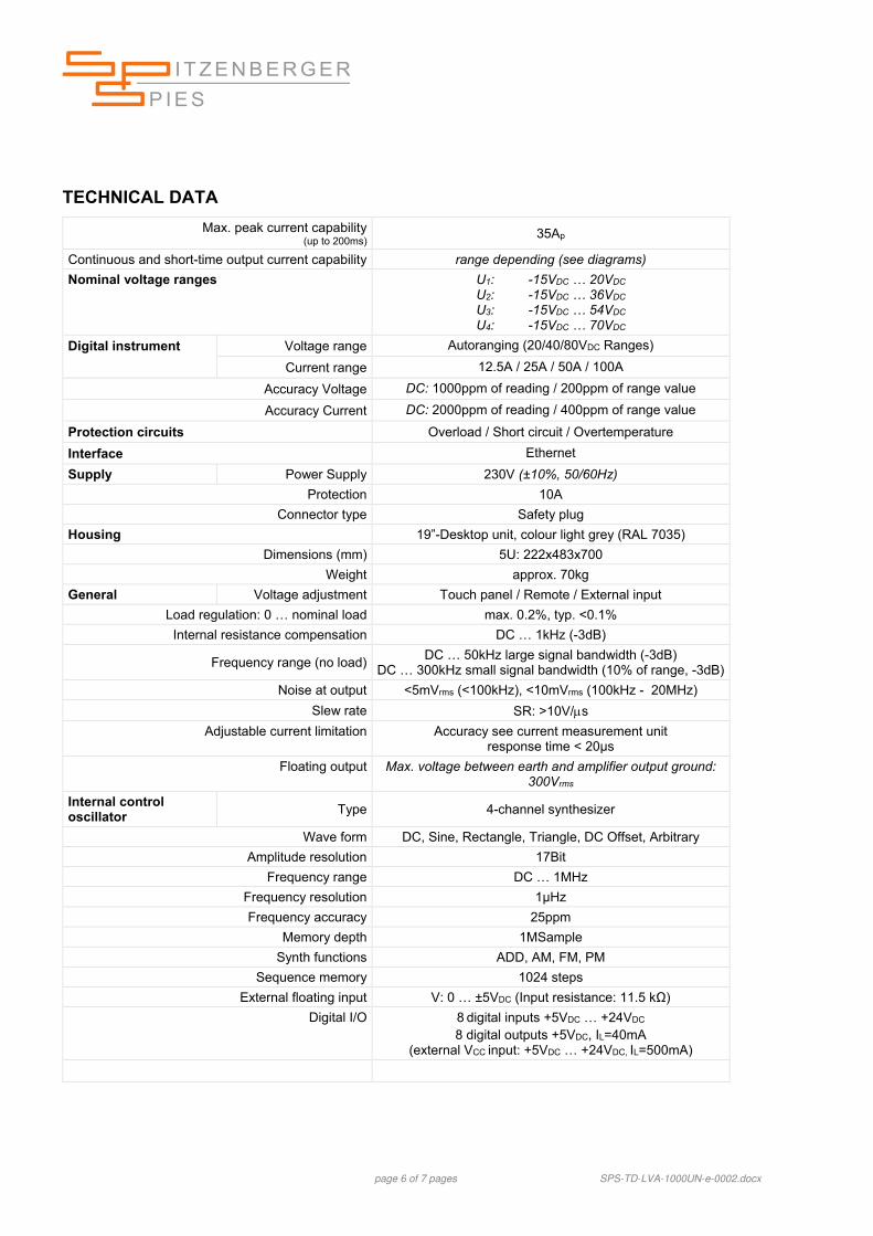
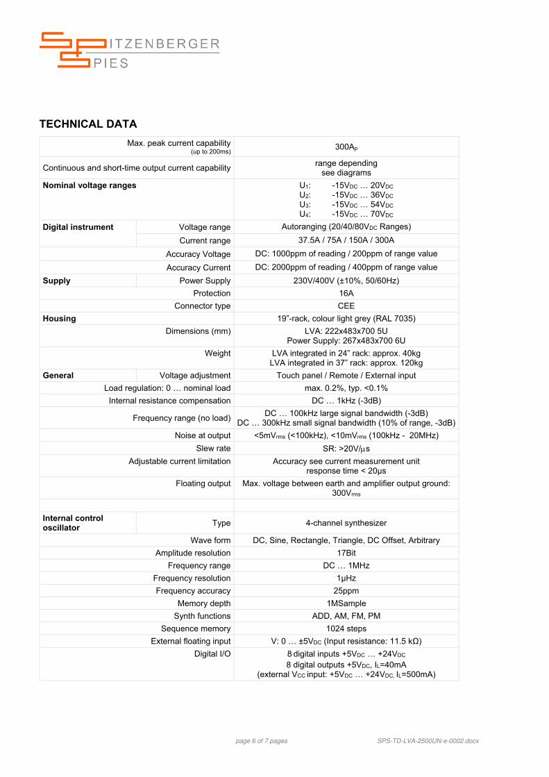
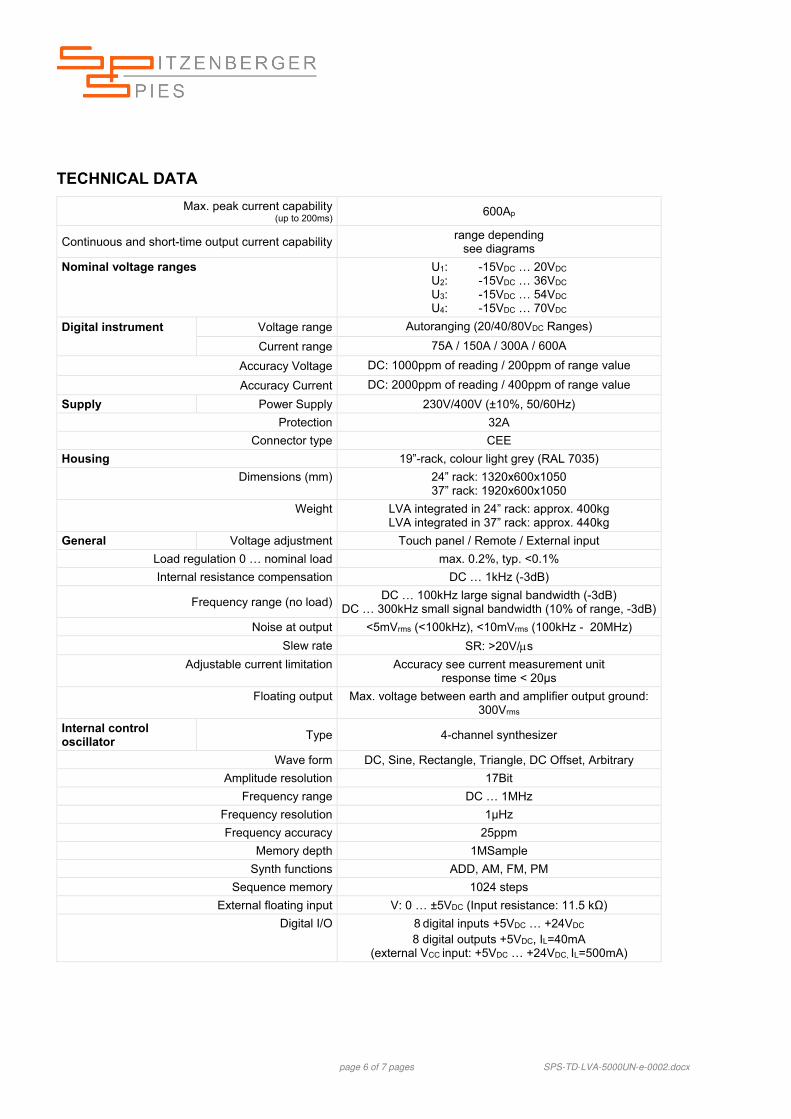
The LVA Amplifier offers four standard voltage ranges: 20VDC 36VDC 54VDC
70VDC Depending on the amplifier’s output stage structure, the voltage ranges can be symmetric or asymmetric. The built in oscillator unit supplies several standard functions: DC signal, Sine wave Rectangular wave Triangular wave Ramp (amplitude sweep) User defined Alternatively, an external sig-nal generator can be used. For each voltage range the operating mode options can be selected. With the option “OPD” (over-voltage protection device) the EUT’s supply voltage is monitored and the EUT is protected against very fast rising high voltage. The LVA allows optionally specifying the amplifier’s internal resistance from 0 to 200mΩ in each mode of operation. Optionally the sink mode capability can be disabled. A built-in measurement unit displays the relevant measurement values.
LVA main menu
LVA oscillator signal selection menu
LVA measurement menu
page 3 of 16 pages SPS-TD-LVA-e-0007.docx
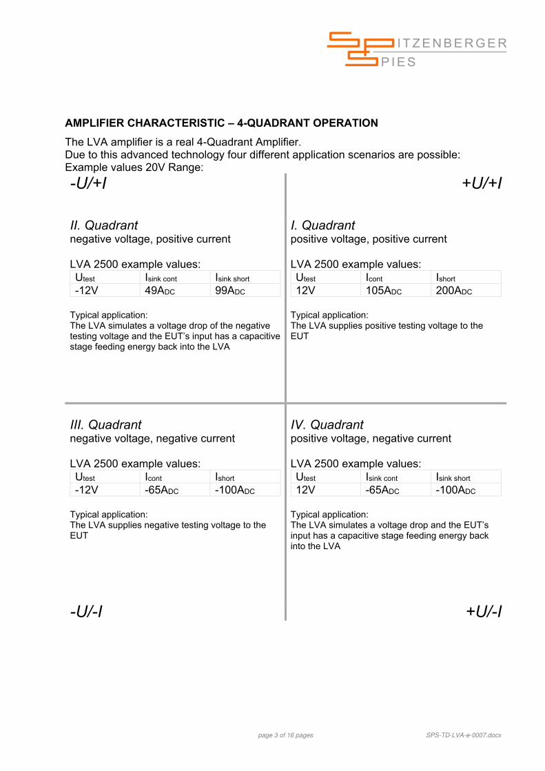
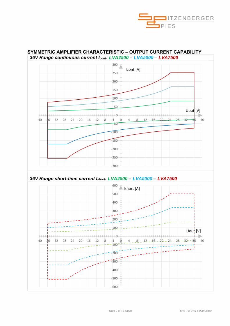
AMPLIFIER CHARACTERISTIC – 4-QUADRANT OPERATION
The LVA amplifier is a real 4-Quadrant Amplifier. Due to this advanced technology four different application scenarios are possible: Example values 20V Range:
-U/+I
+U/+I
II. Quadrant negative voltage, positive current LVA 2500 example values: Utest Isink cont Isink short -12V 49ADC 99ADC
Typical application: The LVA simulates a voltage drop of the negative testing voltage and the EUT’s input has a capacitive stage feeding energy back into the LVA
I. Quadrant positive voltage, positive current LVA 2500 example values: Utest Icont Ishort 12V 105ADC 200ADC
Typical application: The LVA supplies positive testing voltage to the EUT
III. Quadrant negative voltage, negative current LVA 2500 example values: Utest Icont Ishort -12V -65ADC -100ADC
Typical application: The LVA supplies negative testing voltage to the EUT
IV. Quadrant positive voltage, negative current LVA 2500 example values: Utest Isink cont Isink short 12V -65ADC -100ADC
Typical application: The LVA simulates a voltage drop and the EUT’s input has a capacitive stage feeding energy back into the LVA
-U/-I +U/-I
page 4 of 16 pages SPS-TD-LVA-e-0007.docx
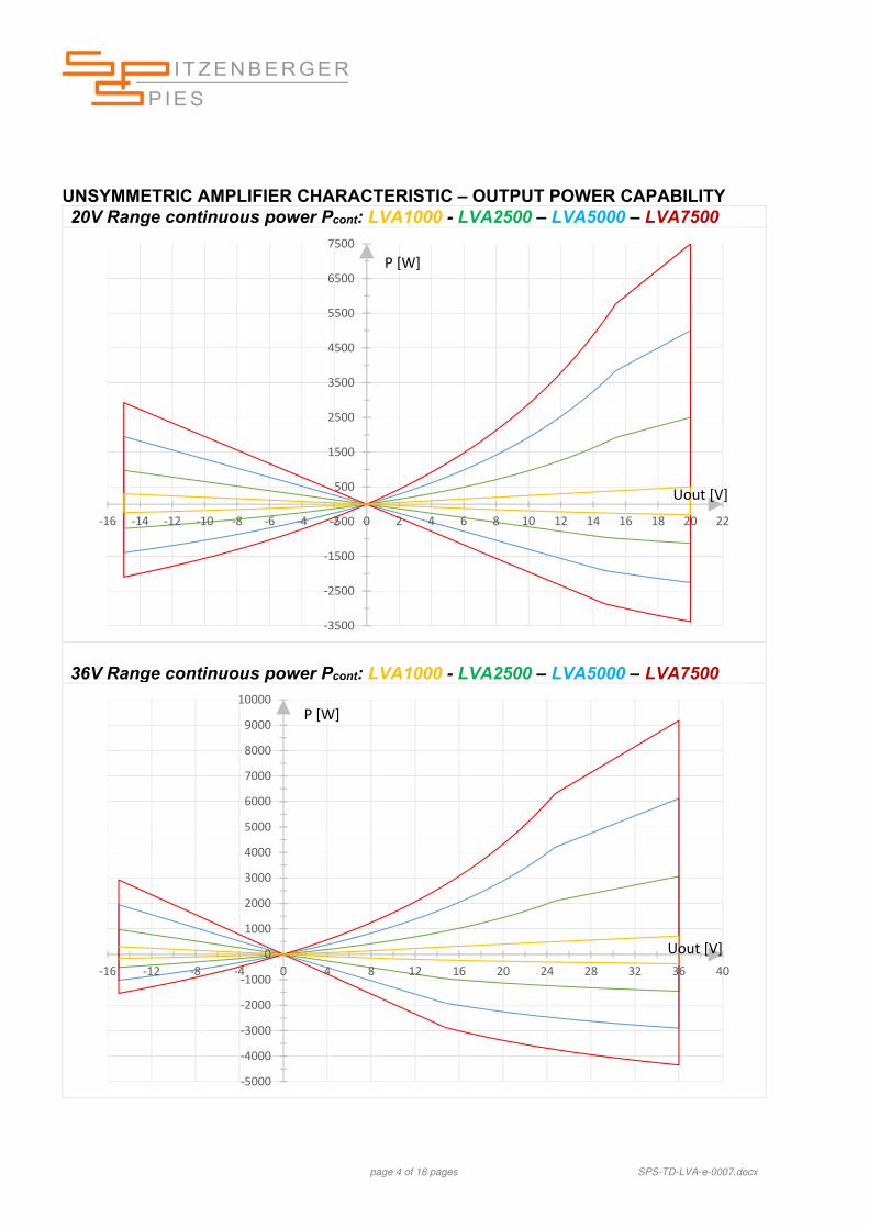
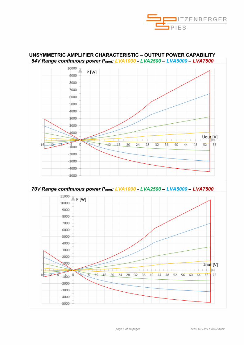
UNSYMMETRIC AMPLIFIER CHARACTERISTIC – OUTPUT POWER CAPABILITY 20V Range continuous power Pcont: LVA1000 - LVA2500 – LVA5000 – LVA7500
36V Range continuous power Pcont: LVA1000 - LVA2500 – LVA5000 – LVA7500
Frequency range: DC … 300kHz small signal bandwidth
Noise at output <5mVrms (<100kHz), <10mVrms (100kHz - 20MHz)
Slew rate (at load=10): U: >20V/s
Protection circuits: Overload / Short circuit / Overtemperature
Input:
Input voltage: (for max. output ) ±5Vp
Interface: Ethernet
Ambient temperature: 10°C up to +40°C Remarks
(1) of range value
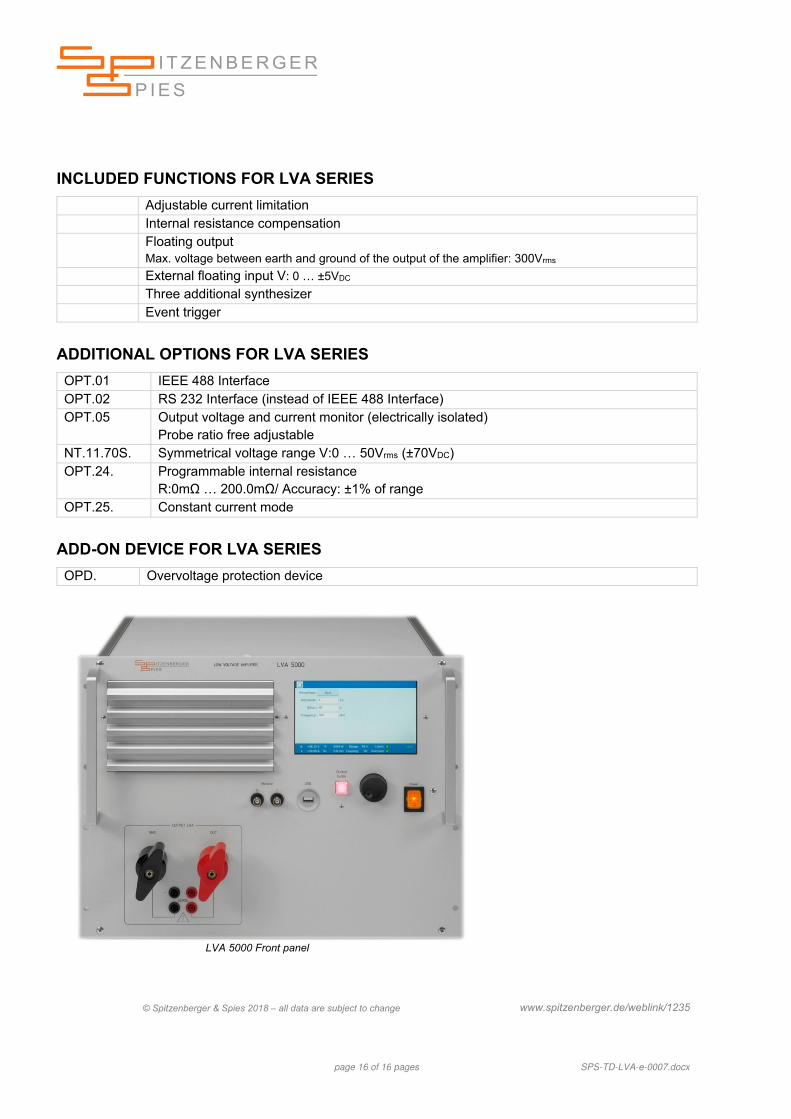
page 16 of 16 pages SPS-TD-LVA-e-0007.docx
INCLUDED FUNCTIONS FOR LVA SERIES
Adjustable current limitation Internal resistance compensation Floating output
Max. voltage between earth and ground of the output of the amplifier: 300Vrms External floating input V: 0 … ±5VDC Three additional synthesizer Event trigger
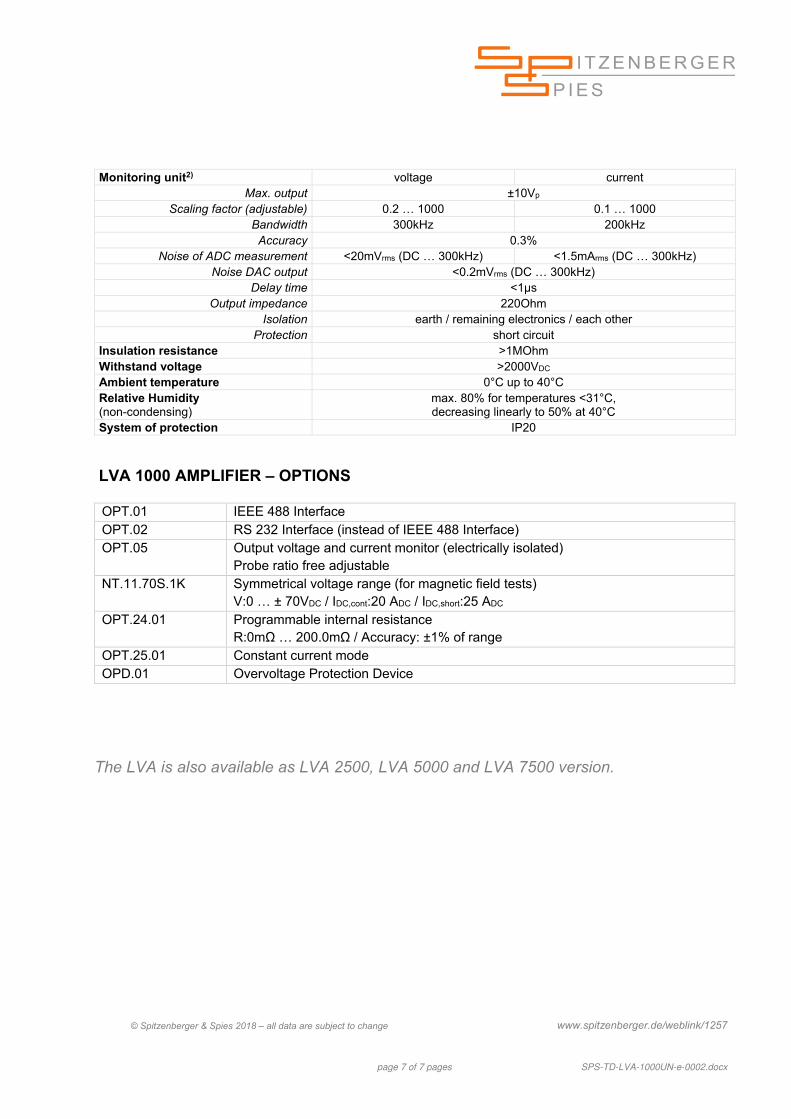
ADDITIONAL OPTIONS FOR LVA SERIES
OPT.01 IEEE 488 Interface OPT.02 RS 232 Interface (instead of IEEE 488 Interface) OPT.05 Output voltage and current monitor (electrically isolated)
Probe ratio free adjustable NT.11.70S. Symmetrical voltage range V:0 … 50Vrms (±70VDC) OPT.24. Programmable internal resistance
R:0mΩ … 200.0mΩ/ Accuracy: ±1% of range OPT.25. Constant current mode
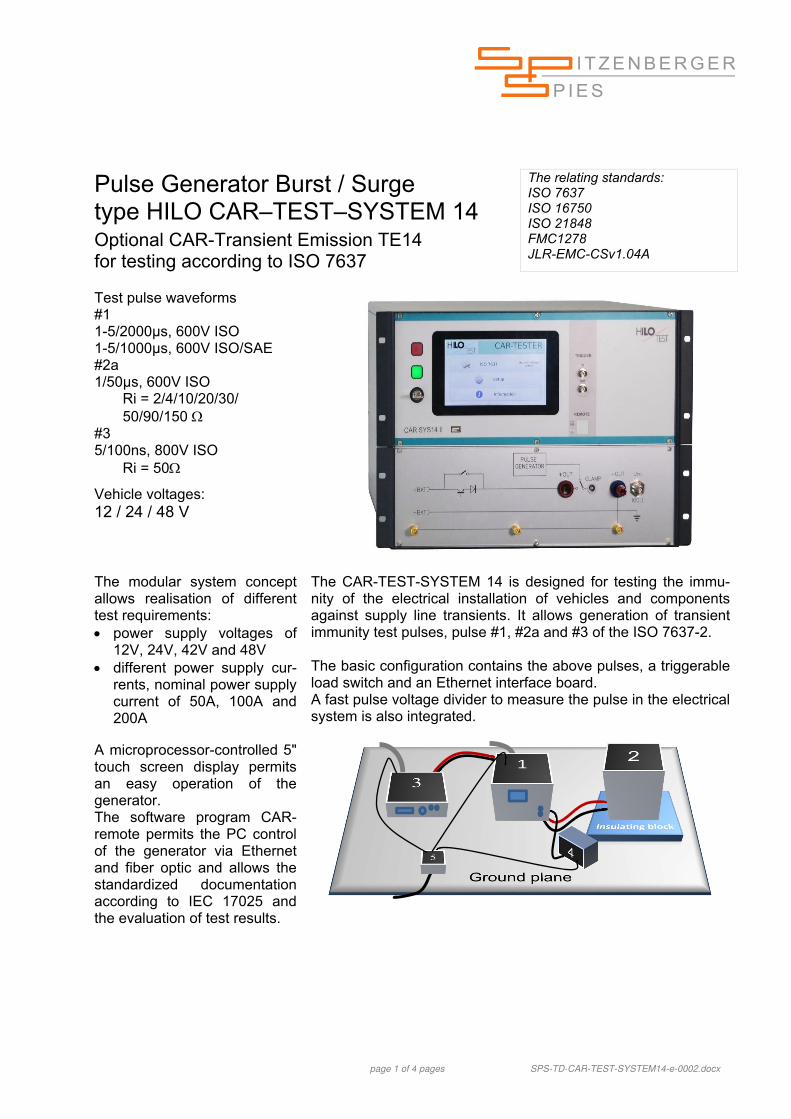
page 1 of 4 pages SPS-TD-CAR-TEST-SYSTEM14-e-0002.docx
Pulse Generator Burst / Surge type HILO CAR–TEST–SYSTEM 14 Optional CAR-Transient Emission TE14 for testing according to ISO 7637
The relating standards: ISO 7637 ISO 16750 ISO 21848 FMC1278 JLR-EMC-CSv1.04A
Test pulse waveforms #1 1-5/2000µs, 600V ISO 1-5/1000µs, 600V ISO/SAE #2a 1/50µs, 600V ISO Ri = 2/4/10/20/30/ 50/90/150 #3 5/100ns, 800V ISO Ri = 50
Vehicle voltages: 12 / 24 / 48 V
The modular system concept allows realisation of different test requirements: power supply voltages of
12V, 24V, 42V and 48V different power supply cur-
rents, nominal power supply current of 50A, 100A and 200A
The CAR-TEST-SYSTEM 14 is designed for testing the immu-nity of the electrical installation of vehicles and components against supply line transients. It allows generation of transient immunity test pulses, pulse #1, #2a and #3 of the ISO 7637-2. The basic configuration contains the above pulses, a triggerable load switch and an Ethernet interface board. A fast pulse voltage divider to measure the pulse in the electrical system is also integrated.
A microprocessor-controlled 5" touch screen display permits an easy operation of the generator. The software program CAR-remote permits the PC control of the generator via Ethernet and fiber optic and allows the standardized documentation according to IEC 17025 and the evaluation of test results.
page 2 of 4 pages SPS-TD-CAR-TEST-SYSTEM14-e-0002.docx
TECHNICAL DATA CAR–TEST–SYSTEM 14 Control: Microprocessor controlled touch-panel 7”, capacitive Optical Ethernet interface for remote control of the generator optional Interface for saving reports USB External trigger input/output 10V at 1k Connector for external safety interlock loop 24VDC Connector for external red and green warning lamps according to VDE 0104 230V, 60W Mains power 230V, 50Hz/60Hz
Housing: Rack mount 7U Dimensions (mm) W * H * D: 450x310x500 Weight (kg): 35 Surge pulse acc. to #1, #2a ISO 7637-2:2011 Charging voltage ± (0V … 600V) ± 10% adjustable Max. stored energy 18J Max. charging time 0.5sec … 5.0sec Switchable Polarity positive, negative Switchable Source resistance 2, 4, 10, 20, 50 or 90, Only with negative pulse polarity: Power supply disconnection time, t2 3 … 200ms ± 20% Trigger delay, t3 < 100µs ISO 7637-2: 5.6.1 Test Pulse 1 (1b SAE) Waveform 1-5/2000μs or 1-5/1000μs Impulse voltage Us 0 … -600V +/-10% Rise time, tr 1.0μs + 0/-0.5μs; 3.0μs +0/-1.5μs Pulse duration, td 2000 μs / 1000 μs ± 20% ISO 7637-2: 5.6.2 Test Pulse 2a Waveform 1-5/2000μs or 1-5/1000μs Impulse voltage Us 0 … +600V +/-10% Rise time, tr 1.0μs +0μs/-0.5μs Pulse duration, td 50μs ± 20% Burst pulse #3a / #3b acc. to ISO 7637-2:2011: Amplitude of burst output voltage ± (25V … 800V) ± 10% adjustable Waveform Rise time, tr 5.0ns ± 30% Pulse duration, td 100ns + 100ns/-0ns Source resistance Rs=50 switchable Polarity pos./neg. Pulse period t1 1.0µs … 1.0ms adjustable Burst duration t4 0.1ms … 25ms adjustable Burst period t5 10ms … 1000ms adjustable Max. continuous burst frequency 20kHz
page 3 of 4 pages SPS-TD-CAR-TEST-SYSTEM14-e-0002.docx
Power supply switch Output current, depending on system type 50A, 100A, 200A Max. reverse voltage 800V Transient over voltage protection >1000V High short circuit current capability 900A Protection with automatic circuit breaker 50A, 100A, 200A Amplifier sense line decoupled from output built-in Trigger input, connectable to external modules built-in Measurement equipment Impulse voltage divider, 4.95 kΩ / 50 Ω 100:1, 1kVpeak PC interface Ethernet 3G built-in
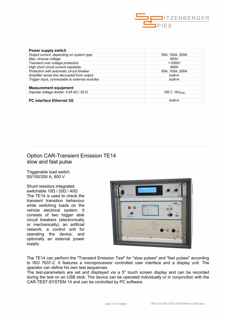
Option CAR-Transient Emission TE14 slow and fast pulse Triggerable load switch 50/100/200 A, 800 V Shunt resistors integrated, switchable 10Ω / 20Ω / 40Ω The TE14 is used to check the transient transition behaviour while switching loads on the vehicle electrical system. It consists of two trigger able circuit breakers (electronically or mechanically), an artificial network, a control unit for operating the device, and optionally an external power supply.
The TE14 can perform the "Transient Emission Test" for "slow pulses" and "fast pulses" according to ISO 7637-2. It features a microprocessor controlled user interface and a display unit. The operator can define his own test sequences. The test-parameters are set and displayed via a 5" touch screen display and can be recorded during the test on an USB stick. The device can be operated individually or in conjunction with the CAR-TEST-SYSTEM 14 and can be controlled by PC software.
page 4 of 4 pages SPS-TD-CAR-TEST-SYSTEM14-e-0002.docx
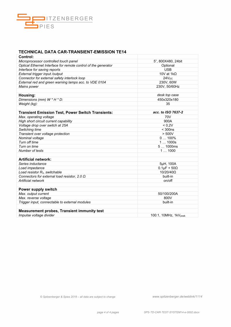
TECHNICAL DATA CAR-TRANSIENT-EMISSION TE14 Control: Microprocessor controlled touch panel 5”, 800X480, 24bit Optical Ethernet Interface for remote control of the generator Optional Interface for saving reports USB External trigger input /output 10V at 1kΩ Connector for external safety interlock loop 24VDC External red and green warning lamps acc. to VDE 0104 230V, 60W Mains power 230V, 50/60Hz Housing: desk top case Dimensions (mm) W * H * D: 450x320x180 Weight (kg): 35 Transient Emission Test, Power Switch Transients: acc. to ISO 7637-2 Max. operating voltage 70V High short circuit current capability 900A Voltage drop over switch at 25A < 0,2V Switching time < 300ns Transient over voltage protection > 500V Nominal voltage 0 … 100% Turn off time 1 … 1000s Turn on time 5 … 1000ms Number of tests 1 … 1000 Artificial network: Series inductance 5μH, 100A Load impedance 0.1μF + 50Ω Load resistor Rs, switchable 10/20/40Ω Connectors for external load resistor, 2.0 Ω built-in Artificial network on/off Power supply switch Max. output current 50/100/200A Max. reverse voltage 800V Trigger input, connectable to external modules built-in Measurement probes, Transient immunity test Impulse voltage divider 100:1, 10MHz, 1kVpeak
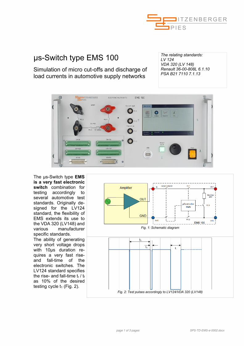
Simulation of micro cut-offs and discharge of load currents in automotive supply networks
The relating standards: LV 124 VDA 320 (LV 148) Renault 36-00-808L 6.1.10 PSA B21 7110 7.1.13
The µs-Switch type EMS is a very fast electronic switch combination for testing accordingly to several automotive test standards. Originally de-signed for the LV124 standard, the flexibility of EMS extends its use to the VDA 320 (LV148) and various manufacturer specific standards.
Fig. 1: Schematic diagram
The ability of generating very short voltage drops with 10µs duration re-quires a very fast rise- and fall-time of the electronic switches. The LV124 standard specifies the rise- and fall-time tr / tf as 10% of the desired testing cycle t1 (Fig. 2).
Fig. 2: Test pulses accordingly to LV124/VDA 320 (LV148)
page 2 of 3 pages SPS-TD-EMS-e-0002.docx
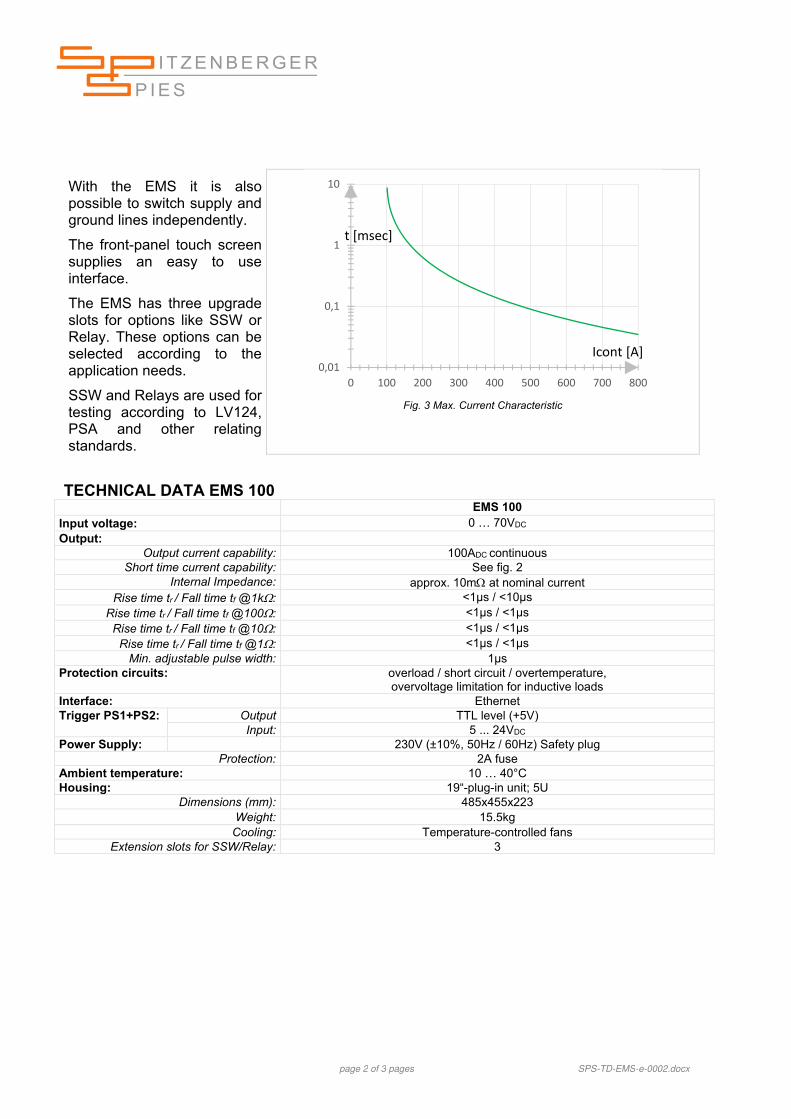
With the EMS it is also possible to switch supply and ground lines independently.
The front-panel touch screen supplies an easy to use interface.
The EMS has three upgrade slots for options like SSW or Relay. These options can be selected according to the application needs.
SSW and Relays are used for testing according to LV124, PSA and other relating standards.
Number of switches: 8 per module Input voltage: 0 … 70VDC
Output current capability: 4ADC Rise time tr / Fall time tf @1k: <1µs / <1µs
Rise time tr / Fall time tf @100: <1µs / <1µs Option: EMS.K.2.16: Relay module 2A/16
Number of relays: 16 per module –contact type 2C Max. switching current (real load): 2ADC Max. switching voltage (real load): 70VDC Max. switching power (real load): 60W
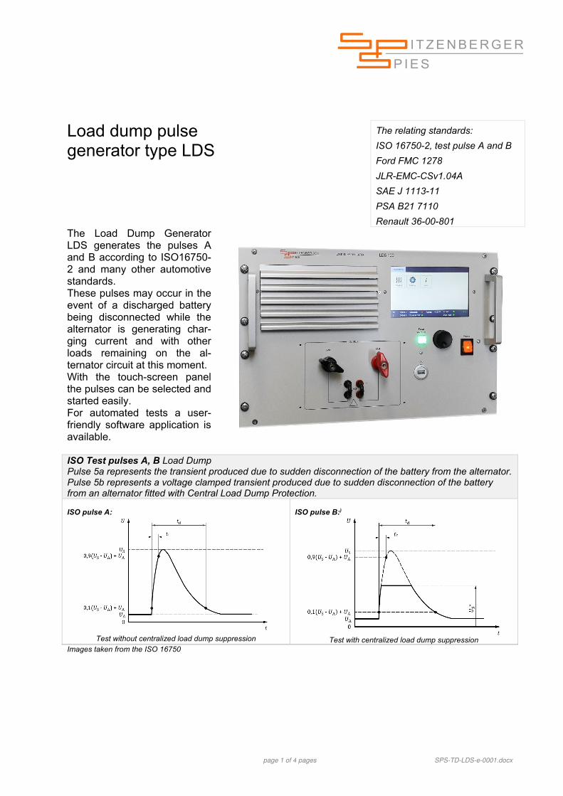
Renault 36-00-801 The Load Dump Generator LDS generates the pulses A and B according to ISO16750-2 and many other automotive standards. These pulses may occur in the event of a discharged battery being disconnected while the alternator is generating char-ging current and with other loads remaining on the al-ternator circuit at this moment. With the touch-screen panel the pulses can be selected and started easily. For automated tests a user-friendly software application is available.
ISO Test pulses A, B Load Dump Pulse 5a represents the transient produced due to sudden disconnection of the battery from the alternator. Pulse 5b represents a voltage clamped transient produced due to sudden disconnection of the battery from an alternator fitted with Central Load Dump Protection. ISO pulse A:
Test without centralized load dump suppression
ISO pulse B:)
Test with centralized load dump suppression
Images taken from the ISO 16750
page 2 of 4 pages SPS-TD-LDS-e-0001.docx
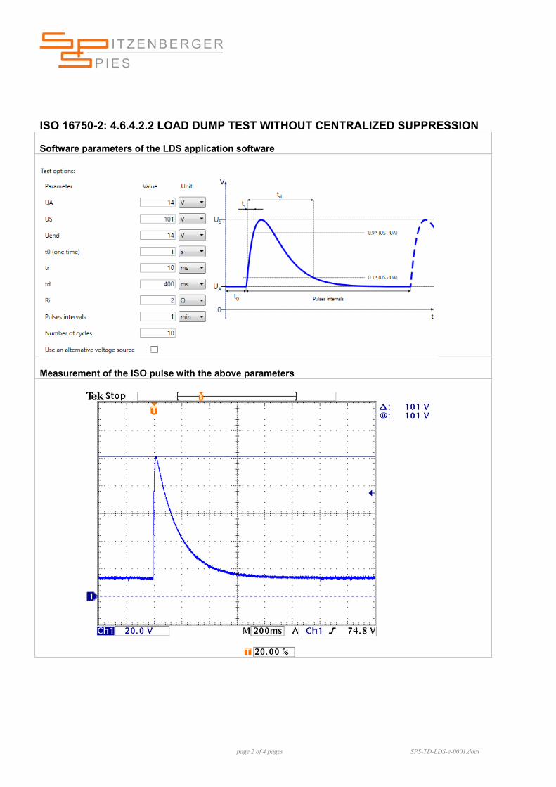
ISO 16750-2: 4.6.4.2.2 LOAD DUMP TEST WITHOUT CENTRALIZED SUPPRESSION Software parameters of the LDS application software
Measurement of the ISO pulse with the above parameters
page 3 of 4 pages SPS-TD-LDS-e-0001.docx
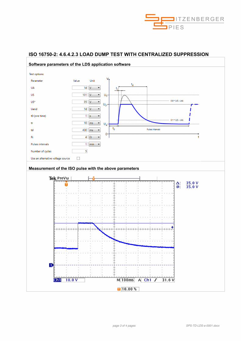
ISO 16750-2: 4.6.4.2.3 LOAD DUMP TEST WITH CENTRALIZED SUPPRESSION Software parameters of the LDS application software
Measurement of the ISO pulse with the above parameters
page 1 of 6 pages SPS-TD-AutomotiveSoftware-Overview-e-0003.docx
SPS Automotive software modules
Supported Windows Versions:
Windows 7
Windows 10
Software modules for automotive standards testing and their requirements of specific hardware
Software module ISO 7637 SAE (S.AU.ISO.7637) Testing according to ISO 7637-2 (2011-03) 4.3 Voltage transient emission test 4.3.2 Test set-up for slow pulses 4.3.3 Test set-up for fast pulses (HARDWARE REQUIREMENT: CAR-SWITCH-TE 14)
5.6 Test pulse generator for immunity testing 5.6.1 Test pulse 1 5.6.2 Test pulses 2a and 2b 5.6.3 Test pulses 3a and 3b (HARDWARE REQUIREMENT: CAR-TEST-SYSTEM 14)
Testing according to ISO 7637-3 (2016-07) 4.3 Test pulse generator 4.3.2 Fast transient test pulses a and b 4.3.3 Slow transient test pulses (HARDWARE REQUIREMENT: CAR-TEST-SYSTEM 14)
Testing according to SAE J 1113-11 (2012-01/2017-06) 8. Test pulses Fig. 2 Test pulse 1, supply disconnection from inductive loads Fig. 3 Test pulse 2a sudden interruption of current Fig. 4 Test pulse 2b transient from dc motors Fig. 5 Test pulse 3a switching spikes Fig. 6 Test pulse 3b switching spikes Fig. 7 Test pulse 4 single pulse (HARDWARE REQUIREMENT: CAR-TEST-SYSTEM 14)
Fig. 8 Test pulse 5a, 5c load dump single pulse unsuppressed Fig. 9 Test pulse 5b load dump single pulse centralized suppression (HARDWARE REQUIREMENT: Load dump generator LDS)
Software module ISO 16750-2 (S.AU.ISO.16750.2) Testing according to ISO 16750-2 (2012-11) 4.2 Direct current supply voltage 4.3 Overvoltage (test pulse for maximum dynamic voltage) 4.4 Superimposed alternating voltage (50Hz … 25kHz) 4.5 Slow decrease and increase of supply voltage 4.6 Discontinuities in supply voltage (HARDWARE REQUIREMENT: Load dump generator LDS)
4.7 Reversed voltage (test at the negative voltage) 4.8 Ground reference and supply offset (HARDWARE REQUIREMENT: Additional amplifier or an external battery)
4.9 Open circuit tests (interruption of supply voltage) 4.10 Short-circuit protection Signal circuits (short circuits are applied to the signal circuits) Load circuits (short circuits are applied to the load circuits) (HARDWARE REQUIREMENT: Electronic switch EMS 100 including option EMS.K.2.16)
page 2 of 6 pages SPS-TD-AutomotiveSoftware-Overview-e-0003.docx
Software module ISO 21848 (S.AU.ISO.21848) Testing according to ISO 21848 (2005-04) 4.1 Direct current (test at the minimum and maximum DC voltage) 4.2 Overvoltages (test pulse for maximum dynamic voltage) 4.3 Superimposed alternating voltage (50Hz … 20 kHz) 4.4 Slow decrease and increase of supply voltage 4.5 Discontinuities in supply voltage 4.6 Reversed voltage (test at the negative voltage) 4.7 Open-circuit tests (interruption of supply voltage) (HARDWARE REQUIREMENT: Electronic switch EMS 100 including option EMS.K.2.16)
4.8 Short-circuit protection Signal circuits (short circuits are applied to the signal circuits) Load circuits (short circuits are applied to the load circuits) (HARDWARE REQUIREMENT: Electronic switch EMS 100 including option EMS.K.2.16)
Software module LV 124 (S.AU.LV124) Testing according to LV 124 (2013-06), BMW GS 95024-3-1 (2013-06), BMW GS 95024-2-2 (2011-02) Mercedes-Benz MBN LV 124-1 (2013-06) and VW 80000 (2013-06/2017-10) E-01 Long-term overvoltage E-02 Transient overvoltage E-03 Transient undervoltage E-04 Jump start E-05 Load dump E-06 Component immunity to ripple on power supply leads (HARDWARE REQUIREMENT: Option OPT.24: programmable internal resistance of the LVA)
E-07 Slow decrease and increase of the supply voltage E-08 Slow decrease, quick increase of the supply voltage E-09 Reset behaviour E-10 Short interruptions (HARDWARE REQUIREMENT: Electronic switch EMS 100)
E-11 Start pulses / cranking profile Test 1 - Cold start Test 2 - Warm start E-12 Voltage curve with IGR E-13 Pin interruption (HARDWARE REQUIREMENT: Electronic switch EMS 100 including Option EMS.SSW)
E-14 Connector interruption (NOTE: For this test E-14 the LVA system provides only the voltage source)
E-15 Reverse polarity (HARDWARE REQUIREMENT: Option OPT.24: programmable internal resistance of the LVA)
E-16 Ground offset (HARDWARE REQUIREMENT: Electronic switch EMS 100 including option EMS.K.2.16 and an additional amplifier or an external battery)
E-17 Short circuit in signal circuit and load circuits (HARDWARE REQUIREMENT: Electronic switch EMS 100 including option EMS.K.2.16 or EMS.SSW.4.8 or EMS.SSW.1.16
E-19 Closed circuit current (HARDWARE REQUIREMENT: External current measurement unit)
Additional / Modified test steps acc. to BMW GS 95024-2-2 (2011-02) E-02 Transient overvoltage (18V pulse) E-11 Start pulses / cranking profile E-19 Quiescent current E-40 Very brief voltage drop E-41 Brief off / on for bus nodes E-42a Voltage impulses due to switch-off of loads (HARDWARE REQUIREMENT: Electronic switch EMS 100 including option EMS.K.2.16)
page 3 of 6 pages SPS-TD-AutomotiveSoftware-Overview-e-0003.docx
Software module LV 148 / VDA 320 (S.AU.LV148) Testing according to LV 148 (2013-09), VDA 320 (2015-01) BMW GS 95026 (2013-10), Mercedes-Benz MBN LV 148 (2013-11) and VW 82148 (2013-09) E48-01a Long-term overvoltage E48-01b Overvoltage in backfeeding components (NOTE: For this test E48-01b the LVA system provides only the voltage source)
E48-02 Transient overvoltage (HARDWARE REQUIREMENT: Option OPT.24: programmable internal resistance of the LVA)
E48-03 Transient process in the lower range with limited function E48-04 Recuperation E48-05 Superimposed AC voltage (HARDWARE REQUIREMENT: Option OPT.24: programmable internal resistance of the LVA)
E48-06 Slow decrease and increase of the supply voltage E48-06 for operation with storage, part 1 E48-06 for operation with storage, part 2 E48-07 Slow decrease, quick increase of the supply voltage E48-08 Reset behaviour E48-09 Short interruptions (HARDWARE REQUIREMENT: Electronic switch EMS 100)
E48-10 Start pulses E48-11 Loss of ground BN48 (HARDWARE REQUIREMENT: Electronic switch EMS 100 including Option EMS.SSW.1.16 and an additional amplifier or an external battery)
E48-12 Ground offset (HARDWARE REQUIREMENT: Electronic switch EMS 100 including option EMS.K.2.16. and an additional amplifier or an external battery)
E48-13 Internal dielectric strength E48-14 Closed-circuit current (HARDWARE REQUIREMENT: External current measurement unit)
E48-15 Operation in the range without functional limitation E48-16 Operation in the upper range with functional limitation E48-17 Operation in the lower range with functional limitation E48-18 Overvoltage range E48-19 Undervoltage range E48-20 Fault current, part 1 and part 2 (NOTE: For this test E48-20 the LVA system provides only the voltage source)
E48-21 Short circuit in signal circuit and load circuits (HARDWARE REQUIREMENT: Electronic switch EMS 100 including option EMS.K.2.16)
Software module BMW GS 95003-2 (S.AU.BMW.95003.2) Testing according to BMW GS 95003-2 (2010-01) 5.2.1.1 Testing for immunity to 18V transient 5.2.1.2 b) Component immunity to ripple on power supply leads 5.2.1.3.1 Slow decreasing / slow increasing of operating voltage 5.2.1.3.2 Slow decreasing / fast rise 5.2.1.3.3 IGR, development of voltage 5.2.1.4 Ground offset (HARDWARE REQUIREMENT: Additional amplifier or an external battery)
5.2.1.5 Cranking profile (Figure 14 and Figure 15) 5.2.1.6 Very brief voltage dip 5.2.1.7 Brief voltage dip 5.2.1.7.1 Brief off / on for bus nodes 5.3.1 Quick chargers / jump start 5.3.3 Protection against polarity reversal
page 4 of 6 pages SPS-TD-AutomotiveSoftware-Overview-e-0003.docx
Software module FORD-FMC 1278 (S.AU.FMC.1278) Testing according to Ford FMC 1278 RI 130 Coupled immunity (HARDWARE REQUIREMENT: Transient generator TDG/Ford, CISPR 25 compliant artificial network, coupling test fixture
RI 150 Coupled immunity (HARDWARE REQUIREMENT: Additional amplifier or external battery, CISPR 25 compliant artificial network, coupling test fixture
CI 210 Immunity from continuous power line disturbances CI 220 Immunity from transient disturbances (HARDWARE REQUIREMENT: For pulses A1, A2-1, A2-2, C1 and C-2 Transient generator TDG/Ford. For pulses E and F1 CAR-TEST-SYSTEM 14. NOTE: The transient pulses G1 and G2 are not covered with this software version
CI 230 Immunity from power cycling (HARDWARE REQUIREMENT: Three additional amplifiers, e.g. LPA 50
CI 250 Immunity to ground voltage offset (HARDWARE REQUIREMENT: Voltage adaption UT Ford CI250 and external battery or second amplifier, LVA option NT.11.70S
CI 260 Immunity to voltage dropout (HARDWARE REQUIREMENT: For waveform F the relay unit in the transient generator TDG/Ford is required.)
CI 270 Immunity to voltage overstress
Software module General Motors GMW 3097 (S.AU.GMW.3097) Testing according to General Motors GMW 3097 (2012-04) 3.5.1 CE, Transients (HARDWARE REQUIREMENT: CAR TE 14)
3.5.2 CI, Transients on power lines (HARDWARE REQUIREMENT: Pulses 1, 2a, 3a and 3b require the CAR-TEST-SYSTEM 14, the simulation of load dump transients requires the load dump generator LDS)
3.5.3 CI, Coupling to other than power supply lines (CCC or DCC to I/O) (HARDWARE REQUIREMENT: Capacitive coupling clamp CDN 2012)
3.5.4 CI, Coupling to other than power supply lines (CCC or DCC to sensors only) (HARDWARE REQUIREMENT: Capacitive coupling clamp CDN 2012)
3.5.5 CI, Coupling to other than power supply lines (DCC on I/O and regulated supply lines) (HARDWARE REQUIREMENT: Capacitive coupling clamp CDN 2012)
3.5.6 CI, Coupling to other than power supply lines (alternator direct capacitor coupling) (HARDWARE REQUIREMENT: Capacitive coupling clamp CDN 2012)
Software module Mitsubishi ES-X82115 (S.AU.Mit.82115) Testing according to Mitsubishi ES-X82115 rev. D (2009-03) 6.1 Supply voltage range 6.2 Ignition off draw (IOD) 6.3 Supply voltage ripple 7.2 Supply voltage drop out (HARDWARE REQUIREMENT: Electronic switch EMS 100)
7.3 Supply voltage dips 7.4 Engine cranking low voltage 7.6 Slow decreases and increase of supply voltage 8.1 Defective regulation (full-fielded alternator) 8.2 Jump start 8.3 Load dump (HARDWARE REQUIREMENT: Load dump generator LDS)
8.4 Reverse supply voltage 9.1 Immunity to short circuits in the supply voltage input and load output lines (HARDWARE REQUIREMENT: Electronic switch EMS 100 including option EMS.K.2.16)
9.2 Immunity to short circuits in I/O signal lines (HARDWARE REQUIREMENT: Electronic switch EMS 100 including option EMS.K.2.16)
9.4 Supply voltage offset (HARDWARE REQUIREMENT: Additional amplifier or an external battery)
9.5 Ground reference offset (HARDWARE REQUIREMENT: Additional amplifier or an external battery)
10.1 Operating and voltage stress 10.2 Stall
page 5 of 6 pages SPS-TD-AutomotiveSoftware-Overview-e-0003.docx
Software module PSA / Renault (S.AU.PSA.REN) Testing according to PSA B21 7110 (2012-07) 7.1 ELECTRICAL RESISTANCE TESTS FOR THE EQUIPMENT CONNECTED TO THE LOW VOLTAGE NETWORK (12V) 7.1.1. EQ/TE 01: Resistance to usual power supply voltages 7.1.2. EQ/TE 08: Resistance to the variations of supply voltage in the usual “voltage control” range (HARDWARE REQUIREMENT: Option OPT.24: programmable internal resistance of the LVA)
7.1.3. EQ/TE 07: Resistance to exceptional supply voltage 7.1.4. EQ/TE 02: Resistance to slow decrease and increase power of supply voltage 7.1.5. EQ/TE 03: Re-initialization test 7.1.6. EQ/TE 04: Resistance to unusual power supply voltages 7.1.7. EQ/TE 05: Resistance to ground and to the positive supply voltages short circuit (HARDWARE REQUIREMENT: Electronic switch EMS 100 including option EMS.K.2.16)
7.1.9. EQ/IC 01: Resistance to pulses 1 and 2a (HARDWARE REQUIREMENT: CAR-TEST-SYSTEM 14)
7.1.10. EQ/IC 10: Resistance to pulses on the outputs switching inductive loads (HARDWARE REQUIREMENT: CAR-TEST-SYSTEM 14) 7.1.11. EQ/IC 02: Resistance to pulses 3a and 3b (HARDWARE REQUIREMENT: CAR-TEST-SYSTEM 14) 7.1.12. EQ/IC 03: Resistance to 5b pulses (HARDWARE REQUIREMENT: Load dump generator LDS)
7.1.13. EQ/IC 04: Resistance to power supply micro interruptions (HARDWARE REQUIREMENT: Electronic switch EMS 100 including option EMS.K.2.16)
7.1.14. EQ/IC 05: Resistance to pulses 4 BIS (HARDWARE REQUIREMENT: Option OPT.24: programmable internal resistance of the LVA)
7.1.15. EQ/IC 12: Resistance to re-start pulse (HARDWARE REQUIREMENT: Option OPT.24: programmable internal resistance of the LVA)
7.1.16. EQ/IC 13: Resistance to “voltage control” voltage pulse (HARDWARE REQUIREMENT: Option OPT.24: programmable internal resistance of the LVA)
7.1.17 EQ/IC 06: Resistance to voltage ripples 7.3 EMC IMMUNITY TESTS (GENERAL CASE) 7.3.1. EQ/IC 07 Immunity to the transients on the signal lines (HARDWARE REQUIREMENT: CAR-TEST-SYSTEM 14 with capacitive coupling clamp CDN 2012)
Testing according to Renault 36-00-808/--M (2012-07) 6.1 RESISTANCE TO ELECTRICAL DISTURBANCES TESTS 6.1.1. EQ/TE 01: Resistance to power supply voltages 6.1.2. EQ/TE 02: Resistance to slow decrease and increase power of supply voltages 6.1.3. EQ/TE 03: Re-initialisation test 6.1.4. EQ/TE 04: Resistance to non-usual power supply voltages 6.1.5. EQ/TE 05: Resistance to ground and positive supply voltages short circuit (HARDWARE REQUIREMENT: Electronic switch EMS 100 including option EMS.K.2.16)
6.1.6. EQ/IC 01: Resistance to pulses 1 and 1bis and 2a (HARDWARE REQUIREMENT: CAR-TEST-SYSTEM 14)
6.1.7. EQ/IC 02: Resistance to pulses 3a and 3b (HARDWARE REQUIREMENT: CAR-TEST-SYSTEM 14)
6.1.10. EQ/IC 04: Resistance to power supply micro interruptions (HARDWARE REQUIREMENT: Electronic switch EMS 100 including option EMS.K.2.16)
6.1.11. EQ/IC 05: Resistance to starting profile 6.1.12. EQ/IC 06 Resistance to on-board power system voltage ripples 6.2 IMMUNITY TO CONDUCTED DISTURBANCE TEST 6.2.1. EQ/IC 07: Immunity to signal line transients (HARDWARE REQUIREMENT: CAR-TEST-SYSTEM 14 with capacitive coupling clamp CDN 2012)
page 6 of 6 pages SPS-TD-AutomotiveSoftware-Overview-e-0003.docx
Software module VW 80000 (S.AU.VW.80000) Testing according to VW 80000 (2013-06/2017-10) E-01 Long-term overvoltage E-02 Transient overvoltage E-03 Transient undervoltage E-04 Jump start E-05 Load dump E-06 Component immunity to ripple on power supply leads (HARDWARE REQUIREMENT: Option OPT.24: programmable internal resistance of the LVA)
E-07 Slow decrease and increase of the supply voltage E-08 Slow decrease, quick increase of the supply voltage E-09 Reset behaviour E-10 Short interruptions (HARDWARE REQUIREMENT: Electronic switch EMS 100)
E-11 Start pulses / cranking profile Test 1 - Cold start Test 2 - Warm start E-12 Voltage curve with IGR E-13 Pin interruption (HARDWARE REQUIREMENT: Electronic switch EMS 100 including Option EMS.SSW.1.16)
E-14 Connector interruption (NOTE: For this test E-14 the LVA system provides only the voltage source)
E-15 Reverse polarity (HARDWARE REQUIREMENT: Option OPT.24: programmable internal resistance of the LVA)
E-16 Ground offset (HARDWARE REQUIREMENT: Electronic switch EMS 100 including option EMS.K.2.16 and an additional amplifier or an external battery)
E-17 Short circuit in signal circuit and load circuits (HARDWARE REQUIREMENT: Electronic switch EMS 100 including option EMS.K.2.16)
E-19 Closed circuit current (HARDWARE REQUIREMENT: External current measurement unit)
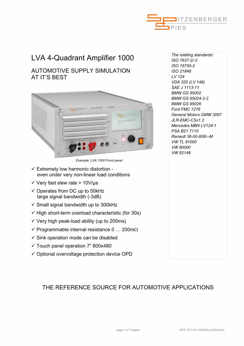
Extremely low harmonic distortion - even under very non-linear load conditions
Very fast slew rate > 10V/µs
Operates from DC up to 50kHz large signal bandwidth (-3dB)
Small signal bandwidth up to 300kHz
High short-term overload characteristic (for 30s)
Very high peak-load ability (up to 200ms)
Programmable internal resistance 0 … 200m
Sink operation mode can be disabled
Touch panel operation 7” 800x480
Optional overvoltage protection device OPD
The relating standards: ISO 7637-2/-3 ISO 16750-2 ISO 21848 LV 124 VDA 320 (LV 148) SAE J 1113-11 BMW GS 95002 BMW GS 95024-2-2 BMW GS 95026 Ford FMC 1278 General Motors GMW 3097 JLR-EMC-CSv1.2 Mercedes MBN LV124-1 PSA B21 7110 Renault 36-00-808/--M VW TL 81000 VW 80000 VW 82148
THE REFERENCE SOURCE FOR AUTOMOTIVE APPLICATIONS
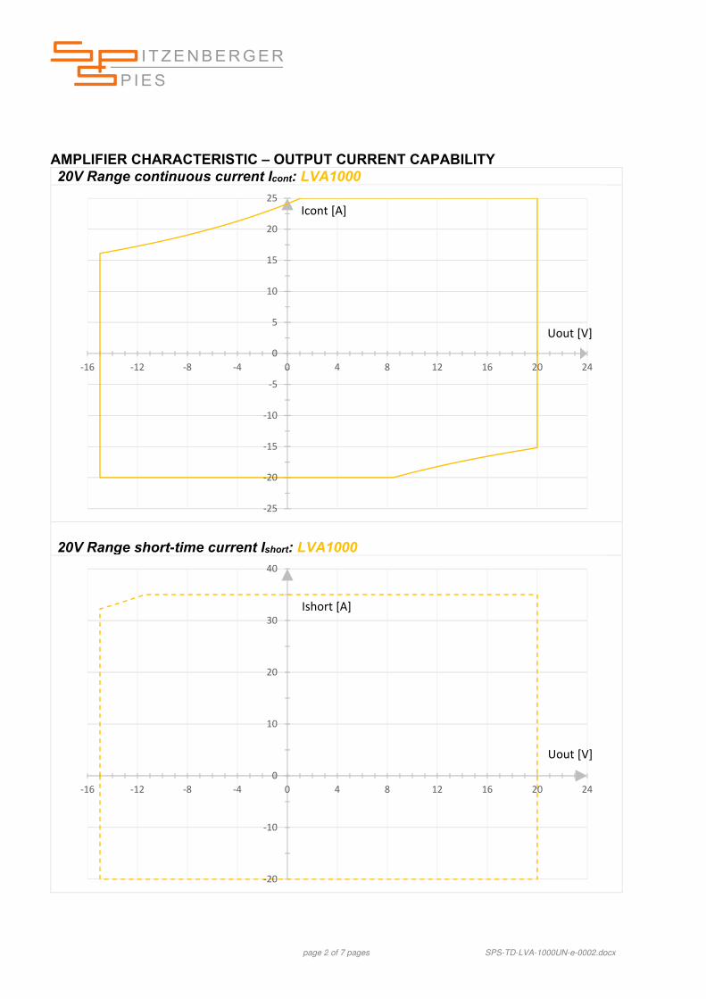
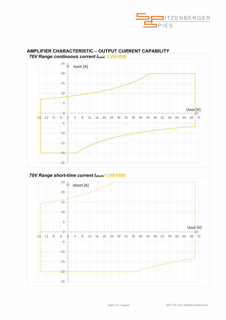
page 2 of 7 pages SPS-TD-LVA-1000UN-e-0002.docx
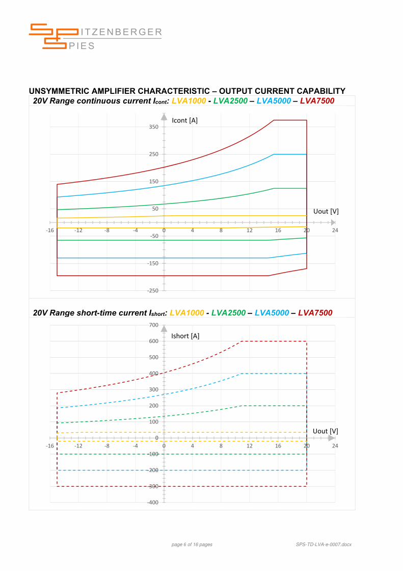
AMPLIFIER CHARACTERISTIC – OUTPUT CURRENT CAPABILITY 20V Range continuous current Icont: LVA1000
20V Range short-time current Ishort: LVA1000
‐25
‐20
‐15
‐10
‐5
0
5
10
15
20
25
‐16 ‐12 ‐8 ‐4 0 4 8 12 16 20 24
Uout [V]
Icont [A]
‐20
‐10
0
10
20
30
40
‐16 ‐12 ‐8 ‐4 0 4 8 12 16 20 24
Ishort [A]
Uout [V]
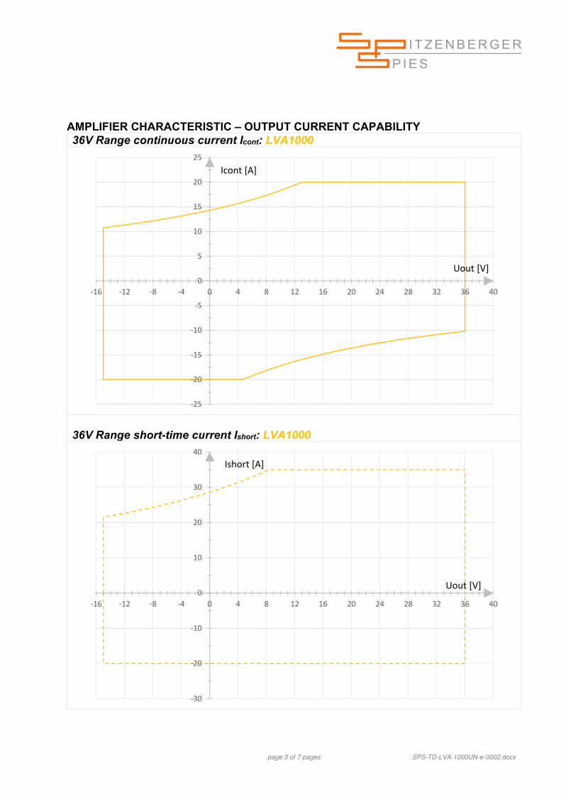
page 3 of 7 pages SPS-TD-LVA-1000UN-e-0002.docx
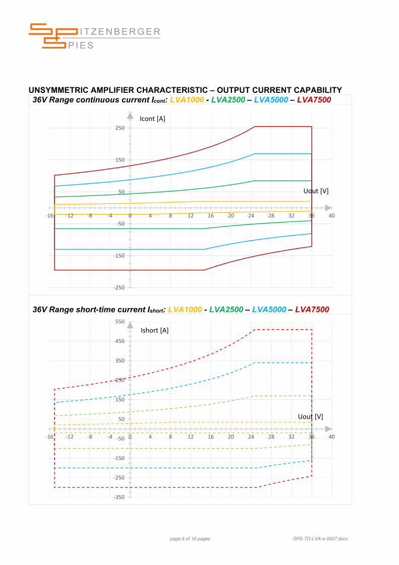
AMPLIFIER CHARACTERISTIC – OUTPUT CURRENT CAPABILITY 36V Range continuous current Icont: LVA1000
36V Range short-time current Ishort: LVA1000
‐25
‐20
‐15
‐10
‐5
0
5
10
15
20
25
‐16 ‐12 ‐8 ‐4 0 4 8 12 16 20 24 28 32 36 40
Icont [A]
Uout [V]
‐30
‐20
‐10
0
10
20
30
40
‐16 ‐12 ‐8 ‐4 0 4 8 12 16 20 24 28 32 36 40
Uout [V]
Ishort [A]
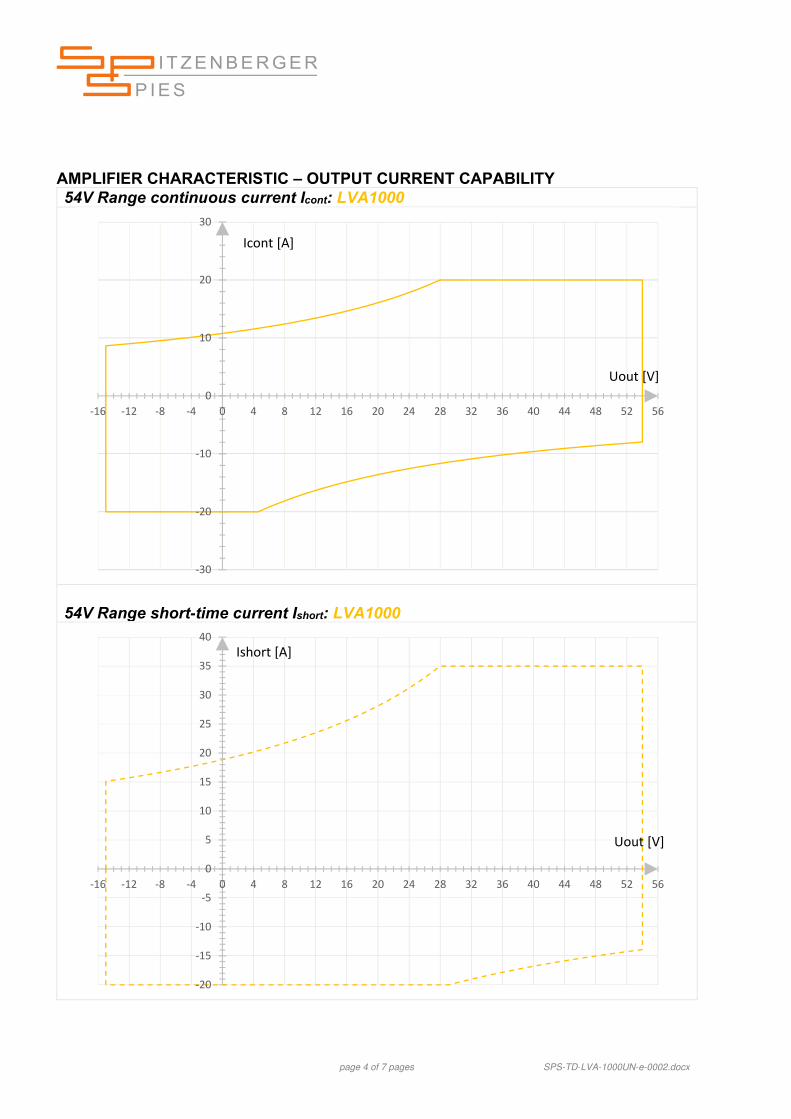
page 4 of 7 pages SPS-TD-LVA-1000UN-e-0002.docx
AMPLIFIER CHARACTERISTIC – OUTPUT CURRENT CAPABILITY 54V Range continuous current Icont: LVA1000
Extremely low harmonic distortion - even under very non-linear load conditions
Very fast slew rate > 20V/µs
Operates from DC up to 100kHz large signal bandwidth (-3dB)
Small signal bandwidth up to 300kHz
High short-term overload characteristic (for 30s)
Very high peak-load ability (up to 200ms)
Programmable internal resistance 0 … 200m
Sink operation mode can be disabled
Touch panel operation 7” 800x480
Optional overvoltage protection device OPD
The relating standards: ISO 7637-2/-3 ISO 16750-2 ISO 21848 LV 124 VDA 320 (LV 148) SAE J 1113-11 BMW GS 95002 BMW GS 95003-2 BMW GS 95024-2-2 BMW GS 95026 DaimlerChrysler DO-10615 Fiat 9.90110 Ford FMC 1278 General Motors GMW 3097 JLR-EMC-CSv1.2 Mercedes-Benz MBN LV124-1 PSA B21 7110 Renault 36-00-808/--M VW TL 81000 VW 80000 VW 82148
THE REFERENCE SOURCE FOR AUTOMOTIVE APPLICATIONS
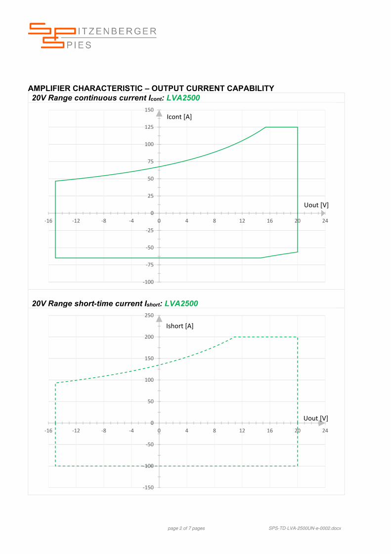
page 2 of 7 pages SPS-TD-LVA-2500UN-e-0002.docx
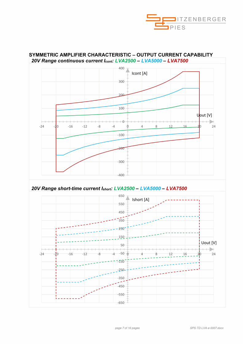
AMPLIFIER CHARACTERISTIC – OUTPUT CURRENT CAPABILITY 20V Range continuous current Icont: LVA2500
20V Range short-time current Ishort: LVA2500
‐100
‐75
‐50
‐25
0
25
50
75
100
125
150
‐16 ‐12 ‐8 ‐4 0 4 8 12 16 20 24
Uout [V]
Icont [A]
‐150
‐100
‐50
0
50
100
150
200
250
‐16 ‐12 ‐8 ‐4 0 4 8 12 16 20 24
Ishort [A]
Uout [V]
page 3 of 7 pages SPS-TD-LVA-2500UN-e-0002.docx
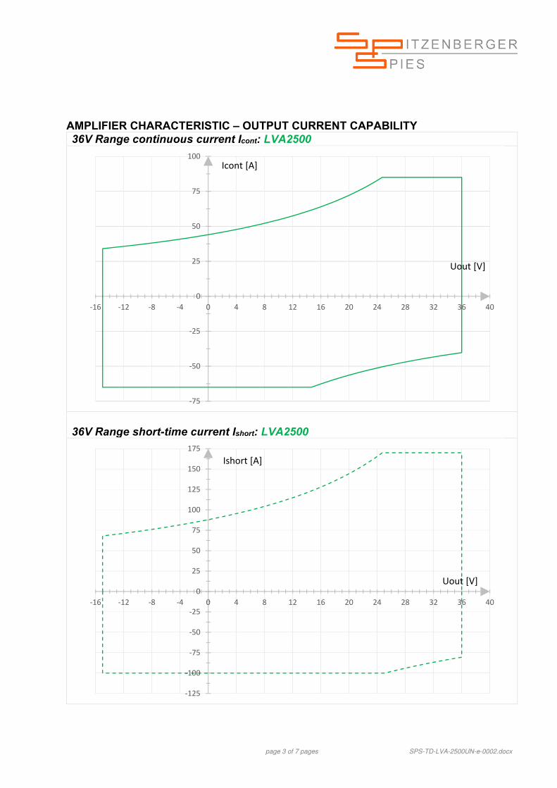
AMPLIFIER CHARACTERISTIC – OUTPUT CURRENT CAPABILITY 36V Range continuous current Icont: LVA2500
36V Range short-time current Ishort: LVA2500
‐75
‐50
‐25
0
25
50
75
100
‐16 ‐12 ‐8 ‐4 0 4 8 12 16 20 24 28 32 36 40
Icont [A]
Uout [V]
‐125
‐100
‐75
‐50
‐25
0
25
50
75
100
125
150
175
‐16 ‐12 ‐8 ‐4 0 4 8 12 16 20 24 28 32 36 40
Uout [V]
Ishort [A]
page 4 of 7 pages SPS-TD-LVA-2500UN-e-0002.docx
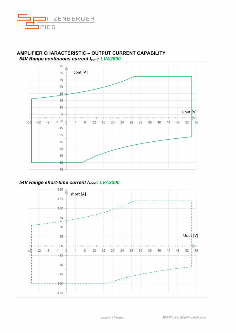
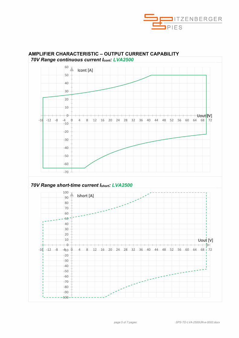
AMPLIFIER CHARACTERISTIC – OUTPUT CURRENT CAPABILITY 54V Range continuous current Icont: LVA2500
Extremely low harmonic distortion - even under very non-linear load conditions
Very fast slew rate > 20V/µs
Operates from DC up to 100kHz large signal bandwidth (-3dB)
Small signal bandwidth up to 300kHz
High short-term overload characteristic (for 30s)
Very high peak-load ability (up to 200ms)
Programmable internal resistance 0 … 200m
Sink operation mode can be disabled
Touch panel operation 7” 800x480
Optional overvoltage protection device OPD
The relating standards: ISO 7637-2/-3 ISO 16750-2 ISO 21848 LV 124 VDA 320 (LV 148) SAE J 1113-11 BMW GS 95002 BMW GS 95003-2 BMW GS 95024-2-2 BMW GS 95026 DaimlerChrysler DO-10615 Fiat 9.90110 Ford FMC 1278 General Motors GMW 3097 JLR-EMC-CSv1.2 Mercedes-Benz MBN LV124-1 PSA B21 7110 Renault 36-00-808/--M VW TL 81000 VW 80000 VW 82148
THE REFERENCE SOURCE FOR AUTOMOTIVE APPLICATIONS
page 2 of 7 pages SPS-TD-LVA-5000UN-e-0002.docx
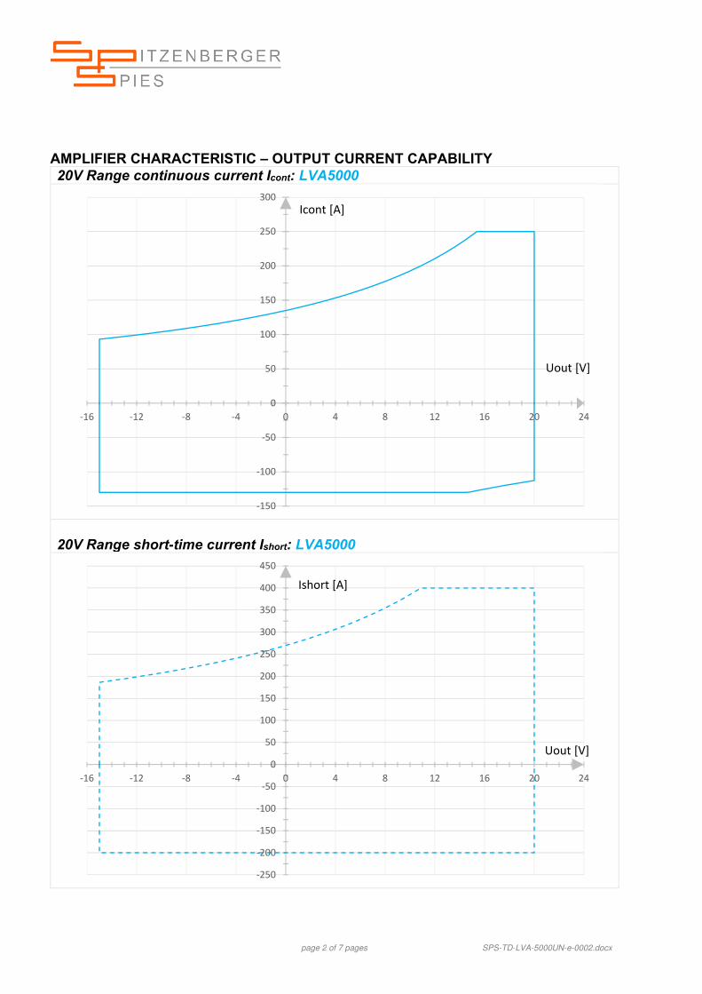
AMPLIFIER CHARACTERISTIC – OUTPUT CURRENT CAPABILITY 20V Range continuous current Icont: LVA5000
20V Range short-time current Ishort: LVA5000
‐150
‐100
‐50
0
50
100
150
200
250
300
‐16 ‐12 ‐8 ‐4 0 4 8 12 16 20 24
Uout [V]
Icont [A]
‐250
‐200
‐150
‐100
‐50
0
50
100
150
200
250
300
350
400
450
‐16 ‐12 ‐8 ‐4 0 4 8 12 16 20 24
Ishort [A]
Uout [V]
page 3 of 7 pages SPS-TD-LVA-5000UN-e-0002.docx
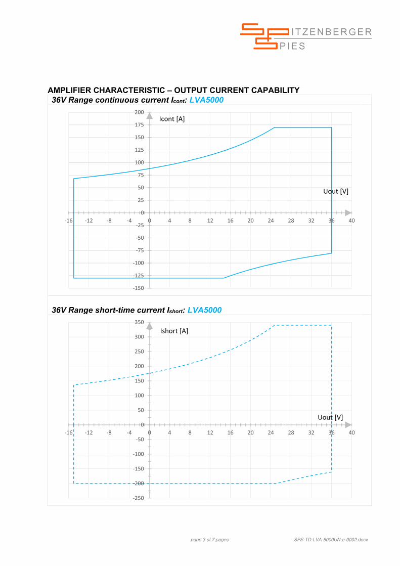
AMPLIFIER CHARACTERISTIC – OUTPUT CURRENT CAPABILITY 36V Range continuous current Icont: LVA5000
36V Range short-time current Ishort: LVA5000
‐150
‐125
‐100
‐75
‐50
‐25
0
25
50
75
100
125
150
175
200
‐16 ‐12 ‐8 ‐4 0 4 8 12 16 20 24 28 32 36 40
Icont [A]
Uout [V]
‐250
‐200
‐150
‐100
‐50
0
50
100
150
200
250
300
350
‐16 ‐12 ‐8 ‐4 0 4 8 12 16 20 24 28 32 36 40
Uout [V]
Ishort [A]
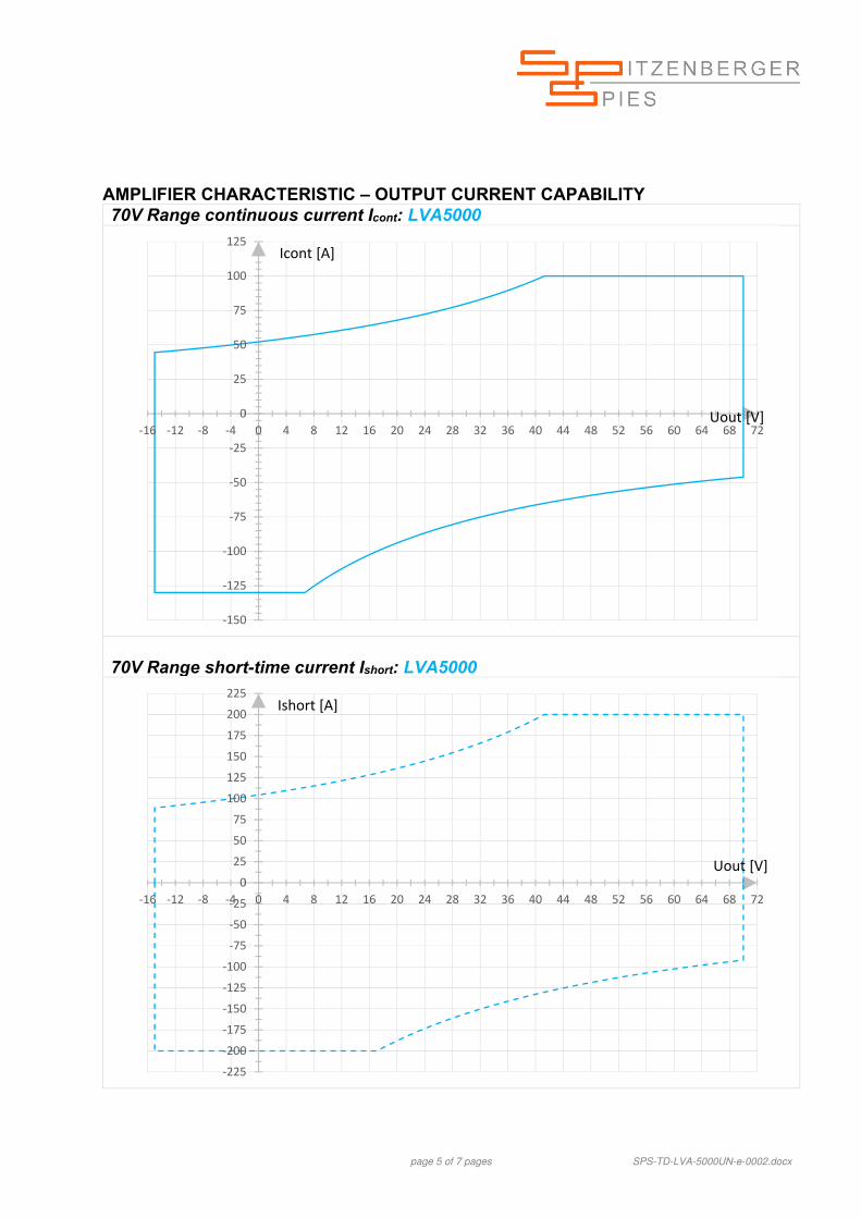
page 4 of 7 pages SPS-TD-LVA-5000UN-e-0002.docx
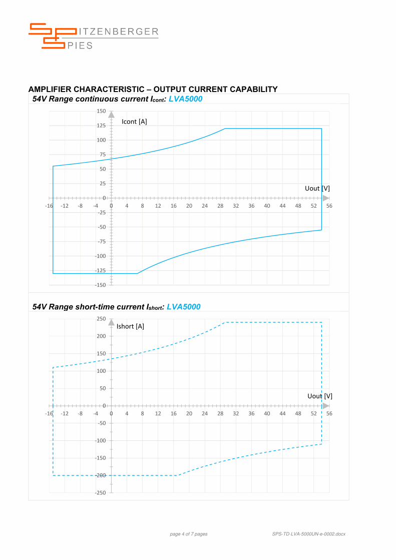
AMPLIFIER CHARACTERISTIC – OUTPUT CURRENT CAPABILITY 54V Range continuous current Icont: LVA5000
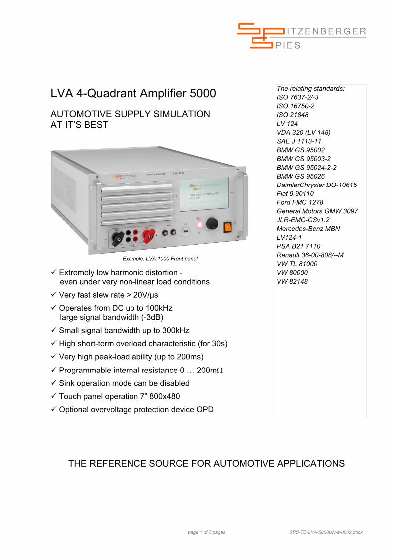
Extremely low harmonic distortion - even under very non-linear load conditions
Very fast slew rate > 20V/µs
Operates from DC up to 100kHz large signal bandwidth (-3dB)
Small signal bandwidth up to 300kHz
High short-term overload characteristic (for 30s)
Very high peak-load ability (up to 200ms)
Programmable internal resistance 0 … 200m
Sink operation mode can be disabled
Touch panel operation 7” 800x480
Optional overvoltage protection device OPD
The relating standards: ISO 7637-2/-3 ISO 16750-2 ISO 21848 LV 124 VDA 320 (LV 148) SAE J 1113-11 BMW GS 95002 BMW GS 95003-2 BMW GS 95024-2-2 BMW GS 95026 Ford FMC 1278 General Motors GMW 3097 JLR-EMC-CSv1.4 Mercedes-Benz MBN LV124-1 PSA B21 7110 Renault 36-00-808/--M VW TL 81000 VW 80000 VW 82148
THE REFERENCE SOURCE FOR AUTOMOTIVE APPLICATIONS
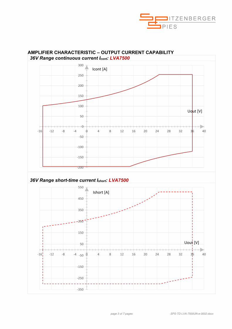
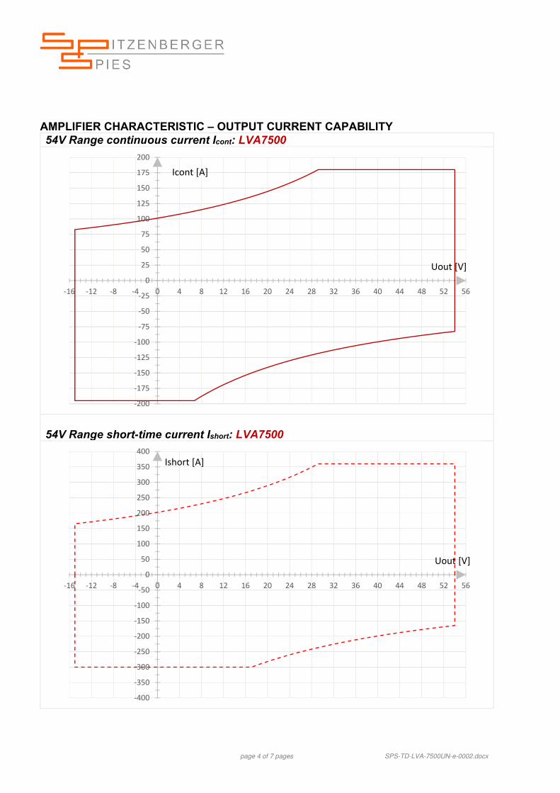
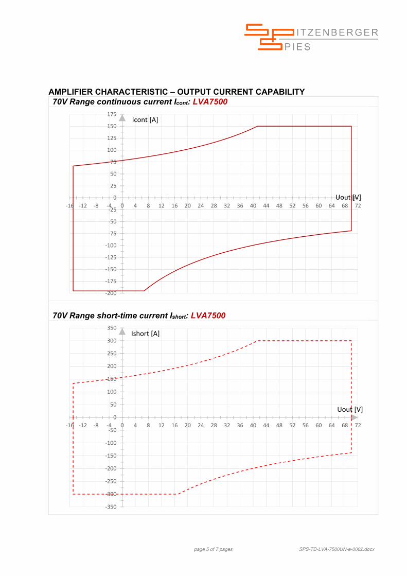
page 2 of 7 pages SPS-TD-LVA-7500UN-e-0002.docx
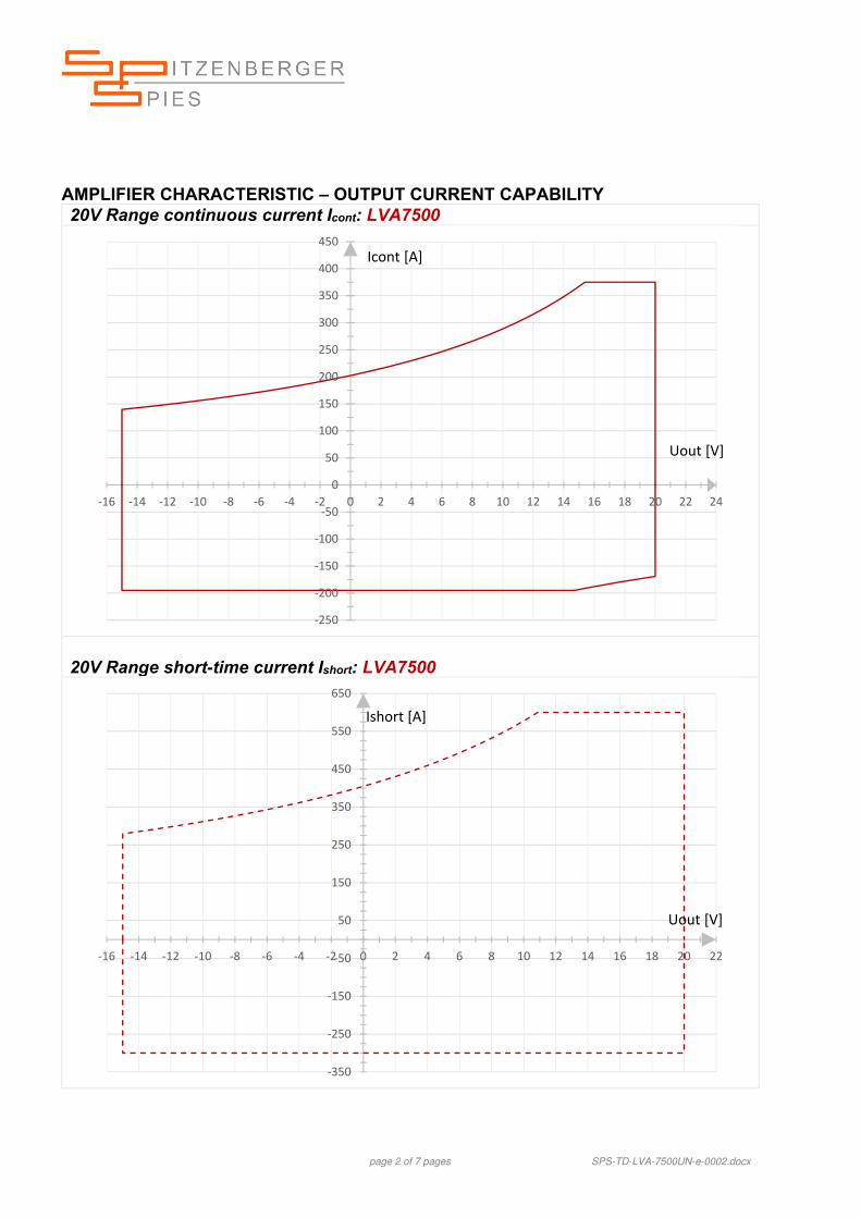
AMPLIFIER CHARACTERISTIC – OUTPUT CURRENT CAPABILITY 20V Range continuous current Icont: LVA7500
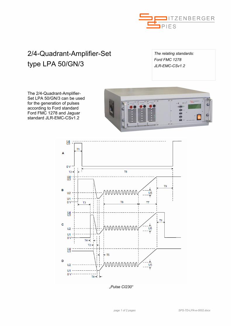
The 2/4-Quadrant-Amplifier-Set LPA 50/GN/3 can be used for the generation of pulses according to Ford standard Ford FMC 1278 and Jaguar standard JLR-EMC-CSv1.2
„Pulse CI230“
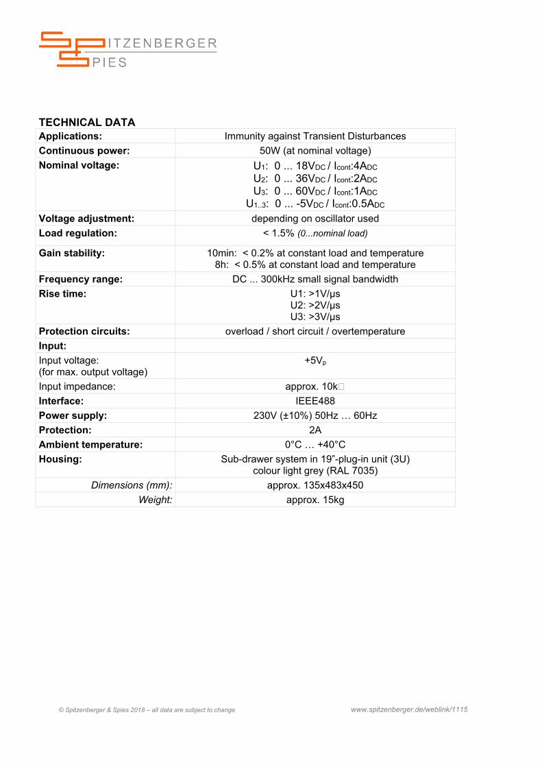
TECHNICAL DATA Applications: Immunity against Transient Disturbances
Continuous power: 50W (at nominal voltage)
Nominal voltage: U1: 0 ... 18VDC / Icont:4ADC
U2: 0 ... 36VDC / Icont:2ADC
U3: 0 ... 60VDC / Icont:1ADC
U1..3: 0 ... -5VDC / Icont:0.5ADC Voltage adjustment: depending on oscillator used
Load regulation: < 1.5% (0...nominal load)
Gain stability: 10min: < 0.2% at constant load and temperature 8h: < 0.5% at constant load and temperature
Frequency range: DC ... 300kHz small signal bandwidth
Rise time: U1: >1V/µs U2: >2V/µs U3: >3V/µs
Protection circuits: overload / short circuit / overtemperature
Input:
Input voltage: (for max. output voltage)
+5Vp
Input impedance: approx. 10k
Interface: IEEE488
Power supply: 230V (±10%) 50Hz … 60Hz
Protection: 2A
Ambient temperature: 0°C … +40°C
Housing: Sub-drawer system in 19”-plug-in unit (3U) colour light grey (RAL 7035)
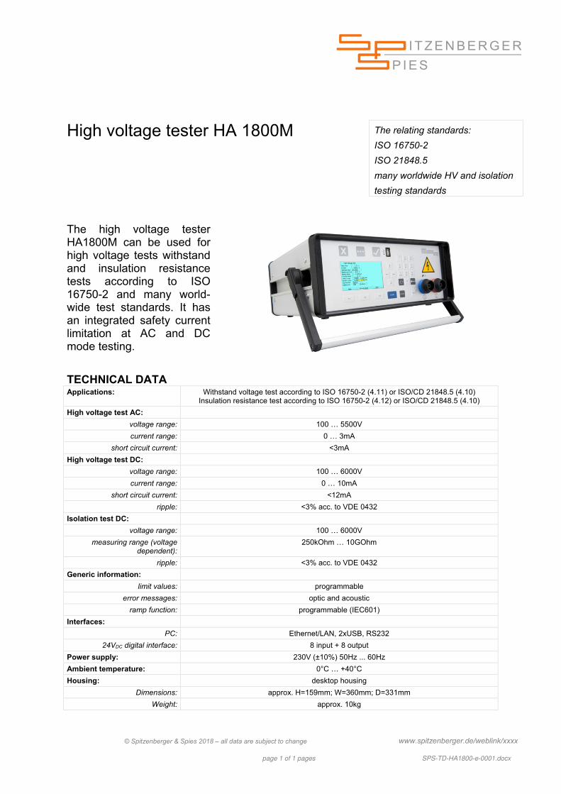
The high voltage tester HA1800M can be used for high voltage tests withstand and insulation resistance tests according to ISO 16750-2 and many world-wide test standards. It has an integrated safety current limitation at AC and DC mode testing.
TECHNICAL DATA Applications: Withstand voltage test according to ISO 16750-2 (4.11) or ISO/CD 21848.5 (4.10)
Insulation resistance test according to ISO 16750-2 (4.12) or ISO/CD 21848.5 (4.10)
"Spitzenberger & Spies offers extra protection for expensive prototype cars" High currents require extra protection devices. Thinking about luxury and upper-class automobiles, currents up to 800A for the initial motor startup are necessary. Everybody can imagine, in which dimensions a simulation system for automotive supply networks has to be.
The relating standards: ISO 7637 ISO 16750-2 ISO 21848 BMW GS 95002 and many manufacturers test specifications
Taking a fully equipped modern limousine as an example, many different power consuming units are on board. Motoric devices as well as high speed heating systems for front windows and lots of other appliances. All of them require immediately high currents for their desired operation.
At the prototyping cycle of current cars in in-house testing facilities (according to ISO 7637 and lots of manufacturer specific test regulations) a programmable DC power supply source with a very high current capability, very short rise time (+/-), very low internal resistance and a very high peak power capability is absolutely necessary. A well-known representative of such a voltage source is the PAS 15000 GN/Kfz, able to deliver short time currents far above 1000A. With such a simulator devices with high-energy needs can be tested also. During any test run the protection of the (mostly expensive) prototype against overvoltage must be most important.
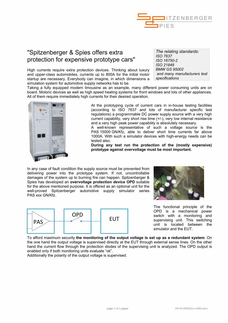
In any case of fault condition the supply source must be prevented from delivering power into the prototype system. If not, uncontrollable damages of the system up to burning fire can happen. Spitzenberger & Spies has developed an overvoltage protection device OPD suitable for the above mentioned purpose. It is offered as an optional unit for the well-proved Spitzenberger automotive supply simulator series PAS xxx GN/Kfz.
The functional principle of the OPD is a mechanical power switch with a monitoring and supervising unit. This switching unit is located between the simulator and the EUT.
To afford maximum security the monitoring of the output voltage is set up as a redundant system. On the one hand the output voltage is supervised directly at the EUT through external sense lines. On the other hand the current flow through the protection diodes of the supervising unit is analyzed. The OPD output is enabled only if both monitoring units evaluate “ok”. Additionally the polarity of the output voltage is supervised.
OPD
EUT PAS
page 2 of 2 pages SPS-FA-OPD2012-e-0002.docx
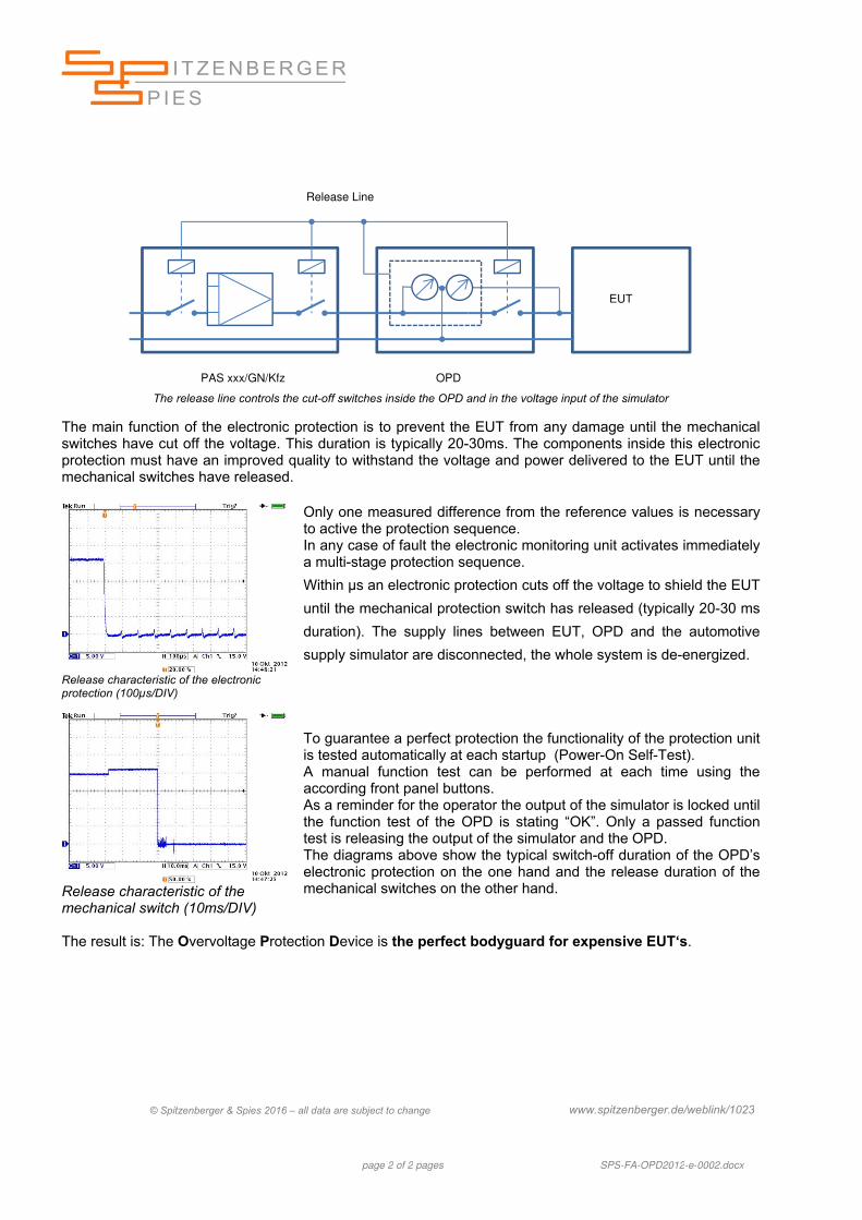
The release line controls the cut-off switches inside the OPD and in the voltage input of the simulator
The main function of the electronic protection is to prevent the EUT from any damage until the mechanical switches have cut off the voltage. This duration is typically 20-30ms. The components inside this electronic protection must have an improved quality to withstand the voltage and power delivered to the EUT until the mechanical switches have released.
Release characteristic of the electronic protection (100µs/DIV)
Only one measured difference from the reference values is necessary to active the protection sequence. In any case of fault the electronic monitoring unit activates immediately a multi-stage protection sequence.
Within µs an electronic protection cuts off the voltage to shield the EUT
until the mechanical protection switch has released (typically 20-30 ms
duration). The supply lines between EUT, OPD and the automotive
supply simulator are disconnected, the whole system is de-energized.
Release characteristic of the mechanical switch (10ms/DIV)
To guarantee a perfect protection the functionality of the protection unit is tested automatically at each startup (Power-On Self-Test). A manual function test can be performed at each time using the according front panel buttons. As a reminder for the operator the output of the simulator is locked until the function test of the OPD is stating “OK”. Only a passed function test is releasing the output of the simulator and the OPD. The diagrams above show the typical switch-off duration of the OPD’s electronic protection on the one hand and the release duration of the mechanical switches on the other hand.
The result is: The Overvoltage Protection Device is the perfect bodyguard for expensive EUT‘s.
page 1 of 2 pages SPS-AN-LVA2500-Risetime-e-0002.docx
Practical measurements Rise- and Fall-Time with the LVA 2500
The relating standards:
ISO 7637
VDA 320
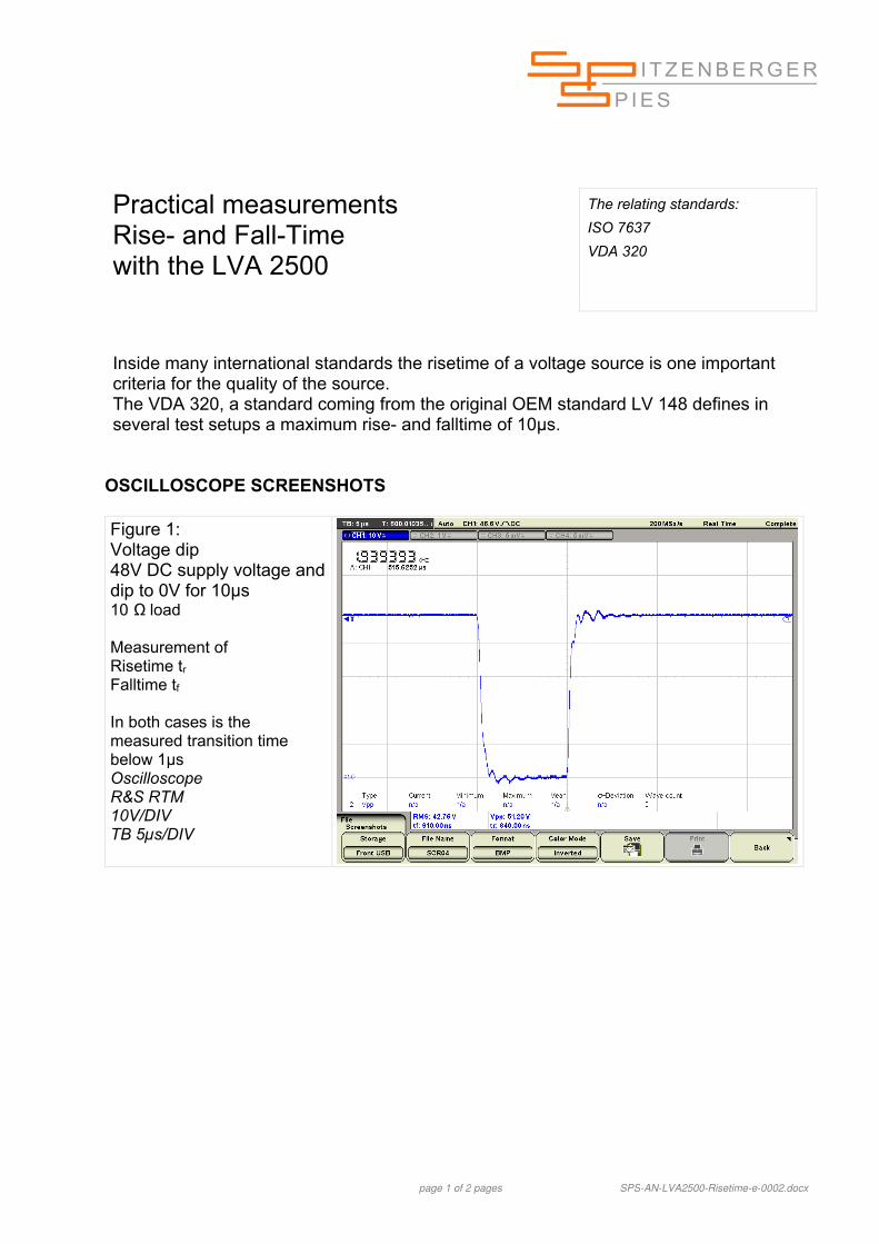
Inside many international standards the risetime of a voltage source is one important criteria for the quality of the source. The VDA 320, a standard coming from the original OEM standard LV 148 defines in several test setups a maximum rise- and falltime of 10µs.
OSCILLOSCOPE SCREENSHOTS Figure 1: Voltage dip 48V DC supply voltage and dip to 0V for 10µs 10 Ω load Measurement of Risetime tr Falltime tf In both cases is the measured transition time below 1µs Oscilloscope R&S RTM 10V/DIV TB 5µs/DIV
page 2 of 2 pages SPS-AN-LVA2500-Risetime-e-0002.docx
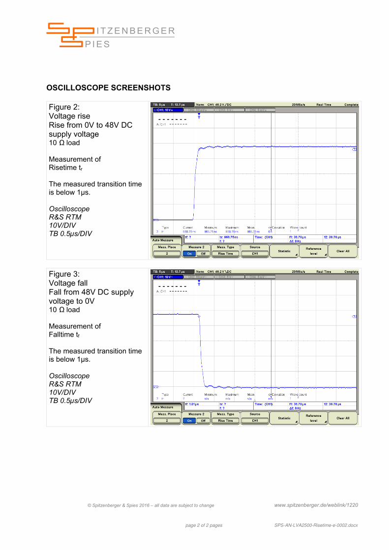
OSCILLOSCOPE SCREENSHOTS Figure 2: Voltage rise Rise from 0V to 48V DC supply voltage 10 Ω load Measurement of Risetime tr The measured transition time is below 1µs. Oscilloscope R&S RTM 10V/DIV TB 0.5µs/DIV
Figure 3: Voltage fall Fall from 48V DC supply voltage to 0V 10 Ω load Measurement of Falltime tf The measured transition time is below 1µs. Oscilloscope R&S RTM 10V/DIV TB 0.5µs/DIV
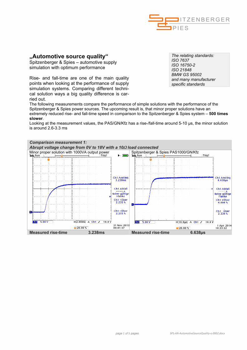
page 1 of 5 pages SPS‐AN‐AutomotiveSourceQuality‐e‐0002.docx
„Automotive source quality“ Spitzenberger & Spies – automotive supply simulation with optimum performance Rise- and fall-time are one of the main quality points when looking at the performance of supply simulation systems. Comparing different techni-cal solution ways a big quality difference is car-ried out.
The relating standards: ISO 7637 ISO 16750-2 ISO 21848 BMW GS 95002 and many manufacturer specific standards
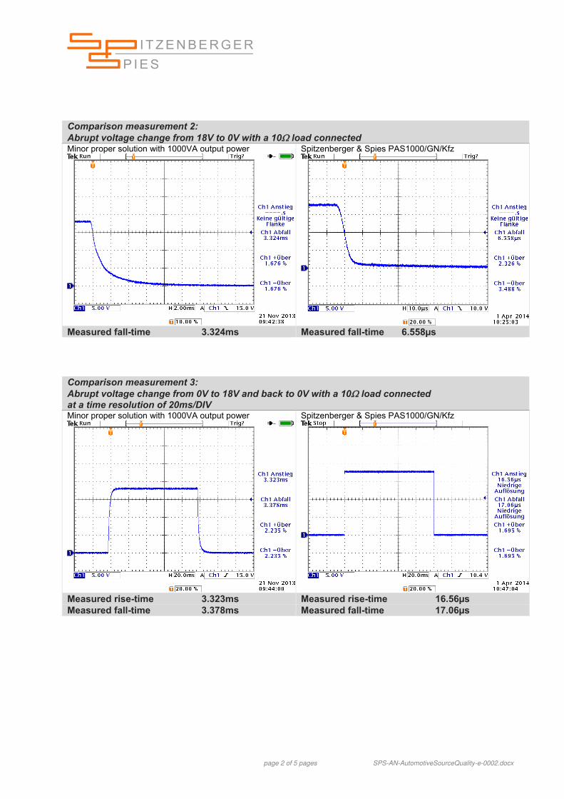
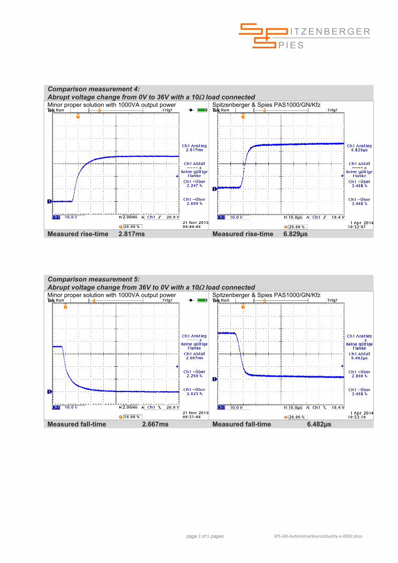
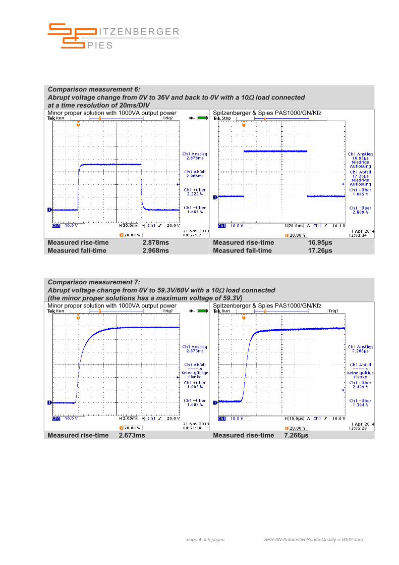
The following measurements compare the performance of simple solutions with the performance of the Spitzenberger & Spies power sources. The upcoming result is, that minor proper solutions have an extremely reduced rise- and fall-time speed in comparison to the Spitzenberger & Spies system – 500 times slower. Looking at the measurement values, the PAS/GN/Kfz has a rise-/fall-time around 5-10 µs, the minor solution is around 2.6-3.3 ms Comparison measurement 1: Abrupt voltage change from 0V to 18V with a 10 load connected Minor proper solution with 1000VA output power Spitzenberger & Spies PAS1000/GN/Kfz
page 2 of 5 pages SPS-AN-AutomotiveSourceQuality-e-0002.docx
Comparison measurement 2: Abrupt voltage change from 18V to 0V with a 10 load connected Minor proper solution with 1000VA output power Spitzenberger & Spies PAS1000/GN/Kfz
Comparison measurement 3: Abrupt voltage change from 0V to 18V and back to 0V with a 10 load connected at a time resolution of 20ms/DIV Minor proper solution with 1000VA output power Spitzenberger & Spies PAS1000/GN/Kfz
page 3 of 5 pages SPS‐AN‐AutomotiveSourceQuality‐e‐0002.docx
Comparison measurement 4: Abrupt voltage change from 0V to 36V with a 10 load connected Minor proper solution with 1000VA output power Spitzenberger & Spies PAS1000/GN/Kfz
Comparison measurement 5: Abrupt voltage change from 36V to 0V with a 10 load connected Minor proper solution with 1000VA output power Spitzenberger & Spies PAS1000/GN/Kfz
page 4 of 5 pages SPS-AN-AutomotiveSourceQuality-e-0002.docx
Comparison measurement 6: Abrupt voltage change from 0V to 36V and back to 0V with a 10 load connected at a time resolution of 20ms/DIV Minor proper solution with 1000VA output power Spitzenberger & Spies PAS1000/GN/Kfz
Comparison measurement 7: Abrupt voltage change from 0V to 59.3V/60V with a 10 load connected (the minor proper solutions has a maximum voltage of 59.3V) Minor proper solution with 1000VA output power Spitzenberger & Spies PAS1000/GN/Kfz
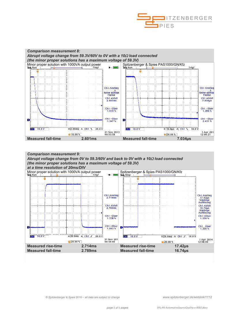
page 5 of 5 pages SPS‐AN‐AutomotiveSourceQuality‐e‐0002.docx
Comparison measurement 8: Abrupt voltage change from 59.3V/60V to 0V with a 10 load connected (the minor proper solutions has a maximum voltage of 59.3V) Minor proper solution with 1000VA output power
Comparison measurement 9: Abrupt voltage change from 0V to 59.3/60V and back to 0V with a 10 load connected (the minor proper solutions has a maximum voltage of 59.3V) at a time resolution of 20ms/DIV Minor proper solution with 1000VA output power Spitzenberger & Spies PAS1000/GN/Kfz