CONTENTS 1 - Introduction 2 - Safety Precautions 3 - Technical Information 4 - Unpacking and Installation Instructions 5 - Electrical Installation 6 - Operating Instructions 7 - Fault Finding 8 - Maintenance and Servicing 9 - General Assembly and Wiring Diagrams 10 - Spare Parts List
1 - Introduction It is imperative that this manual is read carefully and understood before installing your equipment. For your future reference please keep this manual in a safe place. Thank you for specifying a product from the Francis Searchlights range. All Francis products are designed to give complete customer satisfaction and are manufactured to the highest engineering standards in order to ensure optimum performance and service life. The Francis Xenon range combines features proven over many years service in the most hazardous conditions in both marine and land installations. In order to prolong the life and performance of your product, we recommend that you only specify Francis Searchlights spare parts. This will also ensure that any warranties on your equipment will not be invalidated. Information on spares ordering and parts is provided in this manual. Should you ever need to contact Francis Searchlights Ltd. regarding your equipment, please quote the Product Serial Number at all times.
Back To Top
2 - Safety Precautions The following instructions must be adhered to, in order to ensure a safe working environment and the safety of the user. Note: When unpacking or manoeuvring the searchlight into its fixing position, suitable lifting points must be used in order to prevent damage to the equipment or personal injury.
Because of the high internal pressure within the lamp, there is a risk of explosion in either a hot or cold state;
During operation this lamp emits intense UV radiation which is harmful to the eyes and skin. Suitable protection should be worn;
The high luminance of the arc can cause severe damage to the eye if viewed directly. ALWAYS wear suitable protective goggles when viewing the lamp;
Always use protective sleeves supplied with the lamp; Should it be necessary to examine the lamp with the front bezel removed, always use a
protective shield and wear goggles to ensure a safe working environment; Searchlights get hot. Never touch the unit when lit and always allow 15 to 20 minutes for
cooling down after turning the searchlight off; Never place anything on or cover the searchlight when in use; Ensure the lamp has cooled sufficiently before removal; If undue force appears necessary to remove the lamp, the equipment should be inspected by a
competent person or contact the manufacturer; When disposing of lamps, return the lamp, via the supplier, to the lamp manufacturer in its
complete packaging; Due to the vast range of lamps available it may appear possible that more powerful lamps can
be used in the equipment than for which it was designed. Even when the unit will physically accept a higher wattage or voltage lamp, this substitution is not recommended and is dangerous. This action will also void any warranties on the equipment.
Always refer to the lamp manufacturers technical data when dealing with lamps.
Back To Top
3 – Technical Information This product has been designed to operate in accordance with the product specification. The LX300 150watt searchlight has the following features:
All marine grade materials and fixings; Parabolic aluminium deep-dish reflector; Stove enamel painted; Full 360° horizontal rotation; Vertical movement +40° to -35° (Deck); ±25° (Cabin); Remote focus facility; Internal self-regulating heater; Instant lamp re-strike. No cooling down time required; Economical 1200 hour lamp life; Toughened front glass; Supplied with control panel incorporating focus control and on/off switch; Luminous flux 2900; Colour temperature 6000K; Sealing to IP66 Gearbox, IP66 Searchlight, IP67 PSU Box & IP65 Control Box. Deck searchlight weight 16.9 Kgs. Underdeck mechanism 2.3 Kgs. PSU weight 2.7 Kgs. Control panel box assembly 0.5 Kgs.
The searchlight also performs to the following optical data:
Xenon light source Lamp Wattage - 150 Watts; Supply voltage – 24v DC; Peak Beam Candlepower – 6,079,770 lux; Range – 2,465 metres; Adjustable lamp focus, 1.5° spot to 10° flood; Temperature range: -50°C
In order that the searchlight operates correctly it is imperative that competent personnel are responsible for the installation, operation and servicing of this equipment. Failure to adhere to this advice may cause premature failure or incorrect operation of the searchlight, which may damage the equipment or cause personal injury.
Back To Top
4 - Unpacking and Installation Instructions The following instructions should be read and fully understood prior to installing the equipment to ensure that the correct procedures are followed and all safety precautions are observed. Note: If the equipment has been in storage for a considerable amount of time, it is advisable to conduct a routine maintenance check on all parts before installation. Safety Precautions This equipment should not be connected to an electrical supply before being installed. Installation procedures should be adhered to in order to ensure a safe working environment and reduce the risk of damage or personal injury. Preparing the Mounting Position Using the template provided mark out and drill the fixing holes through the deck or cabin roof. In the case of cabin control models, a centre hole is also required to allow the mechanism to pass through. Using the template provided mark out and drill the fixing holes through the deck or cabin roof. In case of cabin control models, a centre hole is also required to allow the mechanism to pass through. For Deck Models Fit the ‘O’ Ring in position and bolt the searchlight base securely down. On an uneven surface it is necessary to use a suitable sealant, such as silicone, in order to ensure a weatherproofed joint. For Pedestal Models Mark out and drill though the deck or cabin roof using the template provided. Remove the cable gland in the base and replace with the blanking plug supplied. Secure the pedestal to the deck using appropriate fixings and then mount the searchlight to the pedestal and secure using the fixings provided. A drilled hole is also required in the deck to allow for the connection to an electrical supply. The searchlight is supplied with 3 metres of supply cable so that the installer can choose a suitable connection point.
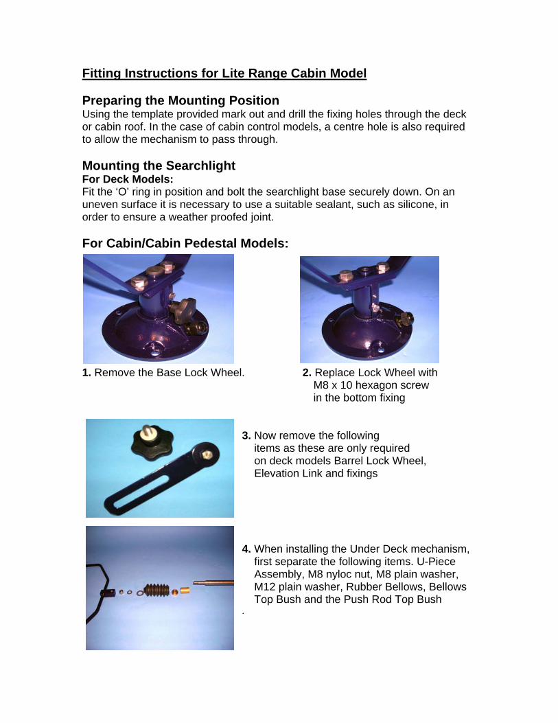
Fitting Instructions for Lite Range Cabin Model Preparing the Mounting Position Using the template provided mark out and drill the fixing holes through the deck or cabin roof. In the case of cabin control models, a centre hole is also required to allow the mechanism to pass through. Mounting the Searchlight For Deck Models: Fit the ‘O’ ring in position and bolt the searchlight base securely down. On an uneven surface it is necessary to use a suitable sealant, such as silicone, in order to ensure a weather proofed joint. For Cabin/Cabin Pedestal Models:
1. Remove the Base Lock Wheel. 2. Replace Lock Wheel with M8 x 10 hexagon screw in the bottom fixing
3. Now remove the following items as these are only required on deck models Barrel Lock Wheel, Elevation Link and fixings 4. When installing the Under Deck mechanism, first separate the following items. U-Piece Assembly, M8 nyloc nut, M8 plain washer, M12 plain washer, Rubber Bellows, Bellows Top Bush and the Push Rod Top Bush .
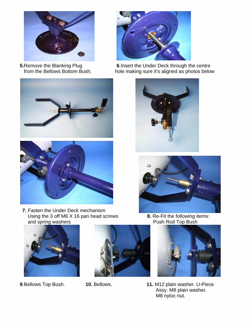
5.Remove the Blanking Plug 6.Insert the Under Deck through the centre from the Bellows Bottom Bush. hole making sure it’s aligned as photos below
7. Fasten the Under Deck mechanism Using the 3 off M6 X 16 pan head screws 8. Re-Fit the following items: and spring washers Push Rod Top Bush
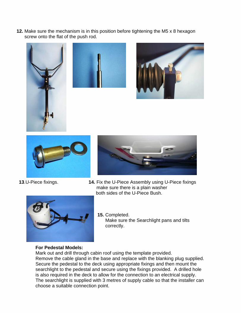
12. Make sure the mechanism is in this position before tightening the M5 x 8 hexagon screw onto the flat of the push rod.
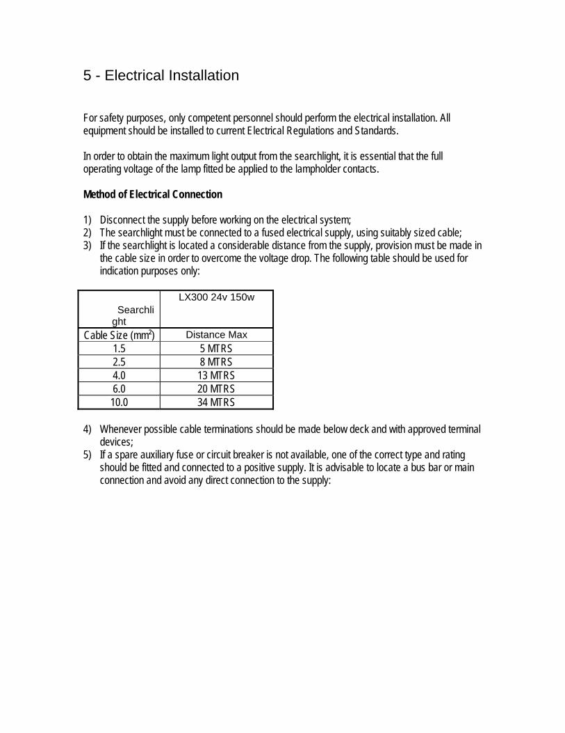
13.U-Piece fixings. 14. Fix the U-Piece Assembly using U-Piece fixings make sure there is a plain washer
both sides of the U-Piece Bush.
ark out and drill through cabin roof using the template provided. emove the cable gland in the base and replace with the blanking plug supplied.
e le
er can
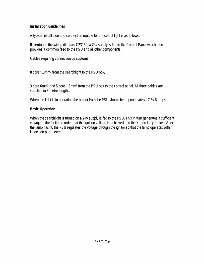
15. Completed. Make sure the Searchlight pans and tilts correctly.
For Pedestal Models: MRSecure the pedestal to the deck using appropriate fixings and then mount thsearchlight to the pedestal and secure using the fixings provided. A drilled ho
also required in the deck to allow for the connection to an electrical supply. isThe searchlight is supplied with 3 metres of supply cable so that the installchoose a suitable connection point.
5 - Electrical Installation
In oitted be applied to the lampholder contacts.
eth d ical C
suppl on the electrical system; t must a fused electrical supply, using suitably sized cable;
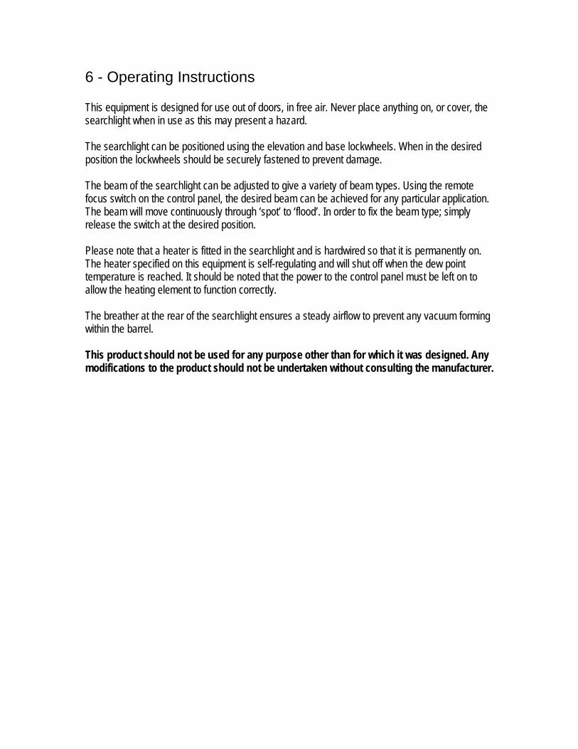
3) If th archlight is locat derable distance from the supply, provision must be made in the cable size in order to overcome the voltage drop. The following table should be used for ind poses only
SearchliLX3 0w
For safety purposes, only competent personnel should perform the electrical installation. All equipment should be installed to current Electrical Regulations and Standards.
rder to obtain the maximum light output from the searchlight, it is essential that the full of the lamp foperating voltage
10.0 34 MTRS 4) Whenever possible cable terminations should be made below deck and with approved terminal
devices; 5) If a spare auxiliary fuse or circuit breaker is not available, one of the correct type and rating
should be fitted and connected to a positive supply. It is advisable to locate a bus bar or main connection and avoid any direct connection to the supply:
Installation Guidelines
archlight is as follows:
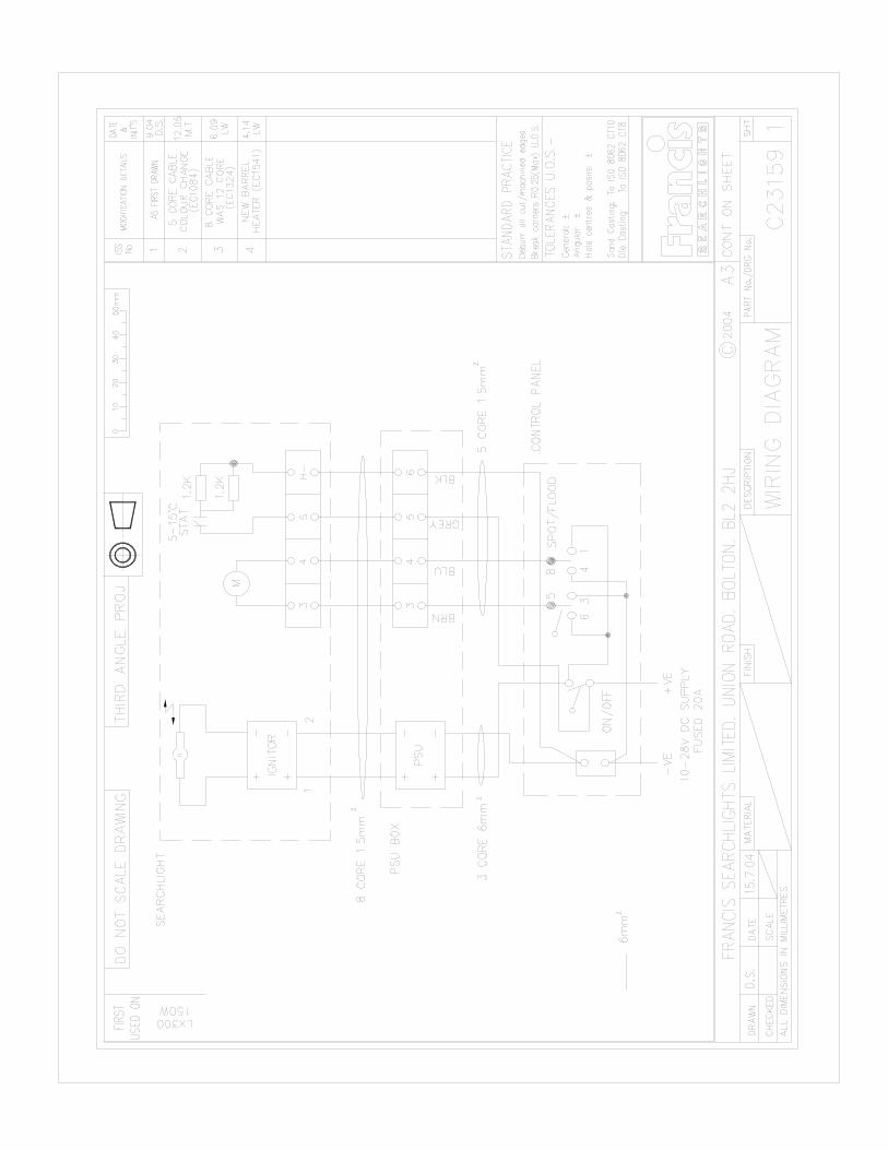
eferring to the wiring diagram C23159, a 24v supply is fed to the Control Panel which then
ables requiring connection by customer:
the searchlight to the PSU box,
When the light is in operation the output from the PSU should be approximately 17.5v 8 amps.
asic Operation When the searchlight is turned on a 24v supply is fed to the PSU. This in turn generates a sufficient oltage to the ig tor in order that the ignition voltage is achieved and the Xenon lamp strikes. After e lamp has lit, the PSU regulates the voltage through the ignitor so that the lamp operates within
s design parameters.
A typical installation and connection routine for the se Rprovides a common feed to the PSU and all other components. C 8 core 1.5mm2 from 3 core 6mm2 and 5 core 1.5mm2 from the PSU box to the control panel. All three cables are supplied in 3 metre lengths.
B
v nithit
Back To Top
6 - Operating Instructions This equipment is designed for use out of doors, in free air. Never place anything on, or cover, the searchlight when in use as this may present a hazard. The searchlight can be positioned using the elevation and base lockwheels. When in the desired position the lockwheels should be securely fastened to prevent damage. The beam of the searchlight can be adjusted to give a variety of beam types. Using the remote ocus switch on the control panel, the desired bef am can be achieved for any particular application.
llow the heating element to function correctly.
he breather at the rear of the searchlight ensures a steady airflow to prevent any vacuum forming ithin the barrel.
his product should not be used for any purpose other than for which it was designed. Any odifications to the product should not be undertaken without consulting the manufacturer.
The beam will move continuously through ‘spot’ to ‘flood’. In order to fix the beam type; simply release the switch at the desired position. Please note that a heater is fitted in the searchlight and is hardwired so that it is permanently on. The heater specified on this equipment is self-regulating and will shut off when the dew point emperature is reached. It should be noted that the power to the control panel must be left on to ta Tw Tm
Setting to W Safe se
should
for
p shattering violently,
of the lamp to be fitted is suitable for the lamphouse and
ly before inserting a lamp;
n corroded areas is not
lamp as mechanical
ays hold it securely by its’ base in order to
ng
reases due to alterations within the quartz; e
Never touch the quartz bulb with bare hands, as fingerprints will make the glass cloudy and cause a severe loss of light. This may also cause recrystallisation and thus weaken the bulb material. Should the bulb be inadvertently touched, remove
be wiped with distilled water. NOTE: ALWAYS WEAR MASK AND GLOVES DURING CLEANING;
All packaging and the protective sleeve must be retained for re-use. Whenever removing a lamp, the protective sleeve must always be used for safety reasons;
lamp manufactur ould be referred to when dealing with
Back To Top
ork
rvice in use necessitates the strict observance of the following precautions.
Any article fabricated from quartz or glass is inherently fragile and caretherefore be taken, at all times, when handling lamps; Eye protection must be worn when handling lamps that have been removed from their packaging materials. The protective sleeve should not be removed from the lamp safety reasons, as there is a remote possibility of the lamespecially if it is subjected to mechanical shock or vibration; Ensure that the power rating power supply equipment; Always isolate the equipment from the supp
Before inserting the lamp ensure that all contacts are clean. Contacts must be renewed at the slightest sign of corrosion. Sanding or filing dowrecommended as this will only make the conducting surface between the pin and lampholder smaller, thus causing the lamp to overheat; Do not twist or bend the fused quartz bulb when fitting thestresses MUST be avoided; When inserting or removing a lamp, alwprevent breakage between base and bulb; The lampholder must not exercise mechanical tensions on the lamp, neither duriinsertion or operation. Contacts must not discolour during use; For safety reasons, the lamp should be replaced once it has reached its’ average life, and not later than 1.25 times the stated life. With continuing use the risk of the lamp exploding inc
Before the protective sleeve is removed, suitable protection must be worn i.e facmask and gloves with wrist protection;
fingerprints with methylated spirit and a clean, soft paper towel. The bulb should then
In all circumstances the lamps.
ers data sh
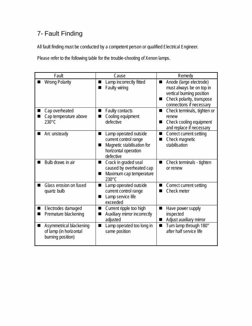
7- Fault Finding
ll fault finding must be conducte erson or qualified E Please refer to the following table for the trouble-shooting of Xenon
A d by a competent p lectrical Engineer.
lamps.
Fault Cause Remedy
olarity rrectly fitted
nspose
f necessary
Wrong P
Lamp inco Faulty wiring
Anode (large electrode) in must always be on top
ositionvertical burning p Check polarity, tra
connections i Cap overheated
bove Check terminals, tighten or
e if necessary
Cap temperature a230°C
Faulty contacts Cooling equipment
defective renew
Check cooling equipment and replac
Arc unsteady
r
Correct current setting Lamp operated outside current control range
Magnetic stabilisation fon horizontal operatio
defective
Check magnetic stabilisation
Bulb draws in air
Crack in graded seal caused by overheated cap
Maximum cap temperature 230°C
Check terminals - tigor renew
hten
Glass erosion on fused quartz bulb
Lamp operated outside current control range
Lamp service life exceeded
Correct current setting
Check meter
Electrodes damaged Premature blackening
Current ripple too high Auxiliary mirror incorrectly
adjusted
Have power supply inspected
Adjust auxiliary mirror Asymmetrical blackening
of lamp (in horizontal burning position)
Lamp operated too long in same position
Turn lamp through 180° after half service life
Fail In th 1)
2) get an operator to switch on the light for approximately 2 seconds. During this time listen for any noise (cracking or hissing) coming
ar
these leads to remove any dust, moisture or condensation that may have formed around the
ny further tests to be carried out with regards to lamp failure must be conducted by a
should not be carried out in an explosive atmosphere.
s ). Switching the lamp on activates the ignitor. A cracking or hissing noise should be
heard. The ignitor is housed within the rear of the searchlight barrel. If found to be faulty a new
Fail
The y a small electric motor situated on the rear bulkhead
be a
1) echanism. If parts have become loose, tighten fasteners. The mechanism operates on a cam action and this should be checked for correct positioning;
) If the mechanism is okay, check the supply to the motor. This can be done by simply placing a multimeter across the motor terminals;
) If supply is present, this indicates that the motor has failed. Replace the focus motor ensuring that the assembly is correct;
If no supply is present there is a fault on panel (check all terminations are secure)
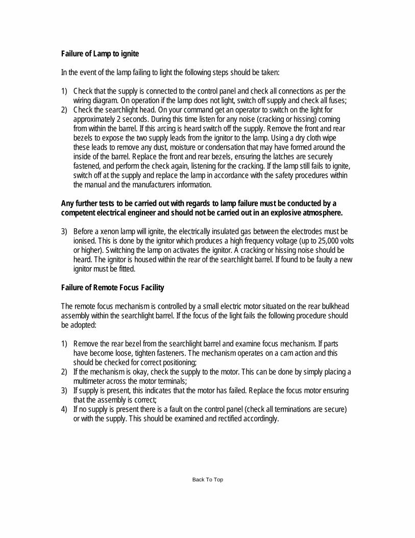
ure of Lamp to ignite
e event of the lamp failing to light the following steps should be taken:
Check that the supply is connected to the control panel and check all connections as per the wiring diagram. On operation if the lamp does not light, switch off supply and check all fuses; Check the searchlight head. On your command
from within the barrel. If this arcing is heard switch off the supply. Remove the front and rebezels to expose the two supply leads from the ignitor to the lamp. Using a dry cloth wipe
inside of the barrel. Replace the front and rear bezels, ensuring the latches are securely fastened, and perform the check again, listening for the cracking. If the lamp still fails to ignite, switch off at the supply and replace the lamp in accordance with the safety procedures within the manual and the manufacturers information.
Acompetent electrical engineer and 3) Before a xenon lamp will ignite, the electrically insulated gas between the electrodes must be
ionised. This is done by the ignitor which produces a high frequency voltage (up to 25,000 voltor higher
ignitor must be fitted.
ure of Remote Focus Facility
remote focus mechanism is controlled bassembly within the searchlight barrel. If the focus of the light fails the following procedure should
dopted:
Remove the rear bezel from the searchlight barrel and examine focus m
2
3
4) the controlor with the supply. This should be examined and rectified accordingly.
Back To Top
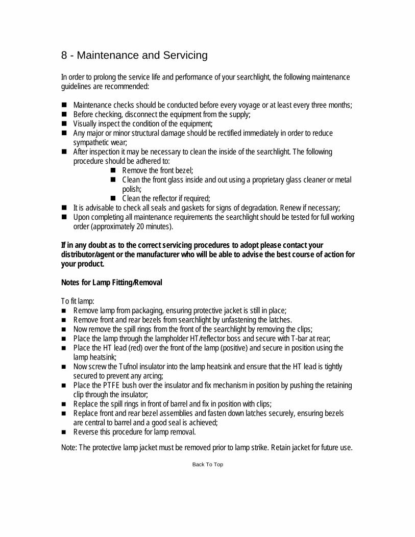
8 - Maintenance and Servicing In order to prolong the service life and performance of your searchlight, the following maintenguidelines are recommended:
ance
Maintenance Before chec Visually insp
Clean the reflector if required; and gaskets for signs of degradation. Renew if necessary; ce requirements the searchlight should be tested for full working
proximately 20 minutes).
act your t of action for
ing the clips;
p heatsink and ensure that the HT lead is tightly
Place the PTFE bush over the insulator and fix mechanism in position by pushing the retaining clip through the insulator;
Replace the spill rings in front of barrel and fix in position with clips; Replace front and rear bezel assemblies and fasten down latches securely, ensuring bezels
ote: The protective lamp jacket must be removed prior to lamp strike. Retain jacket for future use.
Back To Top
checks should be conducted before every voyage or at least every three months; king, disconnect the equipment from the supply; ect the condition of the equipment;
Any major or minor structural damage should be rectified immediately in order to reduce sympathetic wear;
After inspection it may be necessary to clean the inside of the searchlight. The following procedure should be adhered to:
Remove the front bezel; Clean the front glass inside and out using a proprietary glass cleaner or metal
polish;
It is advisable to check all seals Upon completing all maintenan
order (ap If in any doubt as to the correct servicing procedures to adopt please contdis ributor/agent or the manufacturer who will be able to advise the best course your product. Notes for Lamp Fitting/Removal
To fit lamp: Remove lamp from packaging, ensuring protective jacket is still in place; Remove front and rear bezels from searchlight by unfastening the latches. Now remove the spill rings from the front of the searchlight by remov Place the lamp through the lampholder HT/reflector boss and secure with T-bar at rear; Place the HT lead (red) over the front of the lamp (positive) and secure in position using the
lamp heatsink; Now screw the Tufnol insulator into the lam
secured to prevent any arcing;
are central to barrel and a good seal is achieved; Reverse this procedure for lamp removal.
N
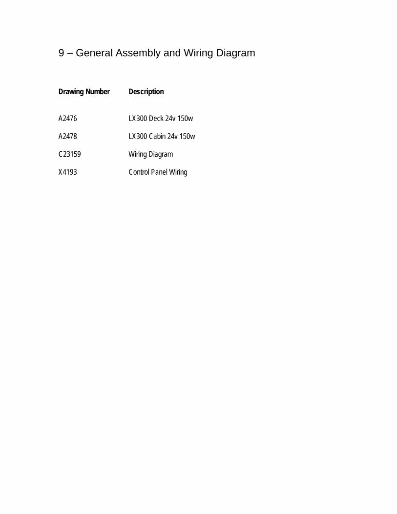
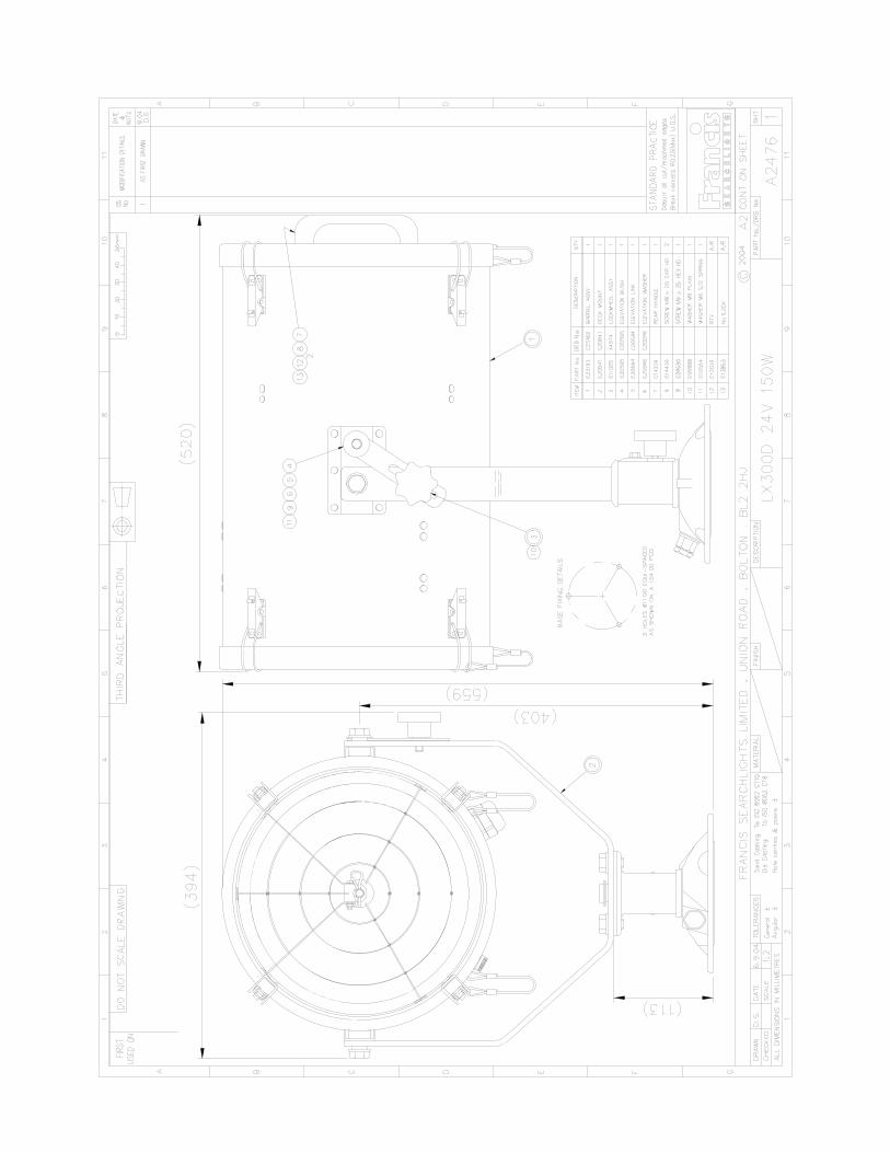
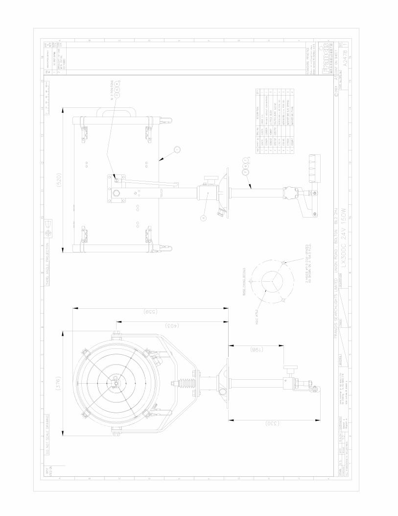
9 – General Assembly and Wiring Diagram
2476 LX300 Deck 24v 150w
2478 LX300 Cabin 24v 150w
23159 Wiring Diagram
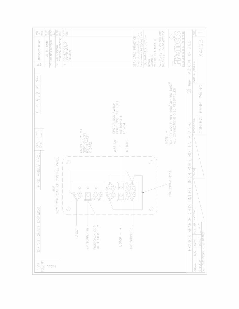
4193 Control Panel Wiring
rawing Number Description D A A C X
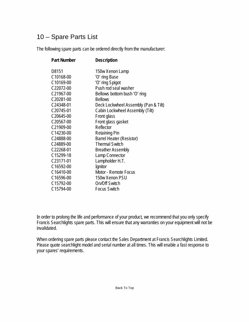
10 – Spare Parts List The following spare parts can be ordered directly from the manufacturer: Part Number Description D8151 150w Xenon Lamp C10168-00 ‘O’ ring Base C10169-00 ‘O’ ring Spigot C22072-00 Push rod seal washer C21967-00 Bellows bottom bush ‘O’ ring C20281-00 Bellows C24348-01 Deck Lockwheel Assembly (Pan & Tilt) C20745-01 Cabin Lockwheel Assembly (Tilt) C20645-00 Front glass C20567-00 Front glass gasket C21909-00 Reflector C14230-00 Retaining Pin C24888-00 Barrel Heater (Resistor) C24889-00 Thermal Switch C22268-01 Breather Assembly C15299-18 Lamp Connector C23171-01 Lampholder H.T. C16592-00 Ignitor C16410-00 Motor - Remote Focus C16596-00 150w Xenon PSU C15792-00 On/Off Switch C15794-00 Focus Switch In order to prolong the life and performance of your product, we recommend that you only specify Francis Searchlights spare parts. This will ensure that any warranties on your equipment will not be invalidated. When ordering spare parts please contact the Sales Department at Francis Searchlights Limited. Please quote searchlight model and serial number at all times. This will enable a fast response to your spares’ requirements.