26
PRODUCT MANUAL T RAINING AND T ECHNOLOGY FOR I NJECTION M OLDING LYNX ™ S HIELDED S EQUENCE M ODULE ID7‑M‑SEQ

PRODUCT MANUAL
Training and Technology for injecTion Molding
Lynx™ Shielded Sequence Module
ID7‑M‑SEQ

PRINT DATE 07.26.2021
REVISION NO. 1
Product Manual | Lynx™ Shielded Sequence Module ID7‑M‑SEQ RJG, Inc. i
PRODUCT MANUALLynx™ Shielded Sequence Module
ID7‑M‑SEQ
INTRODUCTION
DISCLAIMER III
PRIVACY III
ALERTS III
PRODUCT DESCRIPTION
APPLICATIONS 1
PROCESS MONITORING AND CONTROL 1
OPERATION 2
MACHINE SEQUENCE SIGNALS 2
eDART SEQUENCE SIGNALS 4
DIMENSIONS 5
CABLE LENGTHS 5
INSTALLATION
INSTALLATION OVERVIEW 7
ID7‑M‑SEQ 7
eDART CONNECTION 7
INSTALLATION SPECIFICATIONS 8
REQUIREMENTS 8
MOUNTING 8
WIRING 9
CONNECTIONS 10
Lynx™ Shielded Sequence Module ID7‑M‑SEQ | Product Manualii RJG, Inc.
MAINTENANCE
CLEANING 11
REGULAR CLEANING 11
TESTING 11
eDART VERSION 9.XX SOFTWARE 11
eDART VERSION 10.XX SOFTWARE 11
RJG, INC. STANDARD WARRANTY 11
PRODUCT DISCLAIMER 11
TROUBLESHOOTING
COMMON ERRORS 13
SIGNAL ERRORS 13
ACCEPTABLE SIGNAL SUBSTITUTIONS 14
CUSTOMER SUPPORT 15
RELATED PRODUCTS
COMPATIBLE PRODUCTS 17
SHIELDED SEQUENCE MODULE CABLE C‑ID7‑M‑3M 17
LYNX CABLES CE‑LX5 17
eDART PROCESS CONTROLLER 17
SIMILAR PRODUCTS 18
LYNX COMMUNICATIONS ADAPTER DIN/LX‑D 18
LYNX SHIELDED DUAL‑RELAY OUTPUT MODULE OR2‑M 18
LYNX SHIELDED ANALOG INPUT MODULE IA1‑M‑V 18
PRODUCT MANUALlynx™ Shielded Sequence Module
ID7‑M‑SEQ

Product Manual | Lynx™ Shielded Sequence Module ID7‑M‑SEQ RJG, Inc. iii
INTRODUCTION
Read, understand, and comply with all following instructions. This guide must be kept available for reference at all times.
DISCLAIMER
Inasmuch as RJG, Inc. has no control over the use to which others may put this material, it does not guarantee that the same results as those described herein will be obtained. Nor does RJG, Inc. guarantee the effectiveness or safety of any possible or suggested design for articles of manufacture as il lustrated herein by any photographs, technical drawings, and the like. Each user of the material or design or both should make his own tests to determine the suitability of the material or any material for the design as well as the suitability of the material, process, and/or design for his own particular use. Statements concerning possible or suggested uses of the material or designs described herein are not to be construed as constituting a license under any RJG, Inc. patent covering such use or as recommendations for use of such material or designs in the infringement of any patent.
PRIVACY
Designed and developed by RJG, Inc. Manual design, format and structure copyright 2018 RJG, Inc. content documentation copyright 2018 RJG, Inc. All rights reserved. Material contained herein may not be copied by hand, mechanical, or electronic means, either whole or in part, without the express written consent of RJG, Inc. Permission will normally be granted for use in conjunction with inter‑company use not in conflict with RJG’s best interests.
ALERTS
The following three alert types are used as needed to further clarify or highlight information presented in the manual:
Term
A definition of a term or terms used in the text.
NOTE A note provides additional information about a discussion topic.
CAUTION A caution is used to make the operator aware of conditions that can cause damage to equipment and/or injury to personnel.

Lynx™ Shielded Sequence Module ID7‑M‑SEQ | Product Manualiv RJG, Inc.

Product Manual | Lynx™ Shielded Sequence Module ID7‑M‑SEQ RJG, Inc. 1
PRODUCT DESCRIPTION
The Lynx™ shielded sequence module is a DIN‑rail‑mounted module that is wired to the molding machine in order to collect 24 V DC timing signals for use with the eDART® system, including injection forward, screw run, mold closed/clamped, first stage, and mold opening.
The use of an ID7‑M‑SEQ (or a DIN/LX‑D) module is required to physically connect to the eDART system.
APPLICATIONS
PROCESS MONITORING AND CONTROL
The eDART system requires various inputs from the injection molding machine in order to accurately calculate significant process values for monitoring and control.
The ID7‑M‑SEQ gathers the machine sequence state signals from the injection molding machine for the eDART.
The eDART performs computations using the machine sequence state signals from the injection molding machine for various process parameters during a typical cycle. In order for these to be accurate, the eDART generates internal machine sequence signals. These sequences are not necessarily wired to the sequence module, but can be created from signals collected from the module.
For example, the plastic cooling machine sequence is not directly derived from the molding machine, instead it is calculated by the eDART using the mold open signal—a machine‑outputted sequence signal.

Lynx™ Shielded Sequence Module ID7‑M‑SEQ | Product Manual2 RJG, Inc.
OPERATION
MACHINE SEQUENCE SIGNALS
The ID7‑M‑SEQ collects up to seven machine sequence signals from the following: injection forward, first stage, second stage, screw run, mold closed/clamped, mold opening, mold closing, machine in manual mode, machine in auto or semi‑auto mode, shuttle position, and DC common.
The eDART requires, at minimum, the injection forward, screw run, and mold closed/clamped signals from the injection molding machine/ID7‑M‑SEQ. It is critical that the selected signals are correct for the eDART to properly calculate summary values.
1. Injection Forward
Injection forward is the first portion of the molding cycle, during which the ram is being pushed forward; it begins when the injection unit starts to push plastic into the mold and ends when it stops applying pressure (when hold begins).
The eDART uses the injection forward signal as the start of the cycle. Without the injection forward signal, the eDART assumes the machine has stopped.
The eDART computes injection integrals while the injection forward signal is on, ignores peaks in cavity pressures after injection forward is off (a selectable setting), computes hold time, hold pressure, and various other items (detailed below). Injection forward is used by controls such as V→P transfer, shuttle, basic three‑stage, and valve gate to cause the eDART to take certain actions.
2. First Stage
First stage is the portion of the molding cycle during which the machine is injecting; it begins when injection starts, and ends when transfer beings.
3. Second Stage
Second stage is the portion of the molding cycle during which the machine transfers from injection to hold pressure; it begins when transfer starts, and ends when hold ends/recovery begins.

Product Manual | Lynx™ Shielded Sequence Module ID7‑M‑SEQ RJG, Inc. 3
4. Screw Run
Screw run is the portion of the molding cycle during which the machine begins to rotate the screw to build the next shot; it beings when recovery begins and ends when recovery ends (the next shot has been built).
5. Mold Closed/Clamped
The mold closed/clamped signal indicates when the mold is closed during a cycle. If the signal is on only when the mold is clamped, assign it as “mold closed/clamped”. If the signal is on when the mold is closing, assign it as “mold closing”.
6. Mold Opening
The mold opening signal indicates when the mold is opening during a cycle. If the signal is on when the mold is opening, assign it as “mold opening”.
7. Manual
The “manual” signal is assigned to indicate the machine’s current operational mode—machine in manual (mode). The signal must be on only when the machine is in manual mode, and must turn off when it is in auto or semi‑auto mode. This enables the operator to verify that the other sequence signals are correctly wired and assigned by cycling the different functions while in manual mode to verify that the corresponding sequence signal module light is activated.
8. Shuttle Position
The shuttle position signal (for use with shuttle molding tables only) indicates to the eDART in which position the table is currently—Shuttle Position A, B, C, etc.
OPERATION (continued)

Lynx™ Shielded Sequence Module ID7‑M‑SEQ | Product Manual4 RJG, Inc.
eDART SEQUENCE SIGNALS
The eDART can calculate the following sequences from the aforementioned, hard‑wired machine sequence signals. These sequences will vary based on the available hard‑wired signals provided from the machine.
1. Fill
The fil l signal is generated by the eDART from machine signals; fi l l will go on as the screw passes through the position to which it recovered just before decompress and will go off when the second‑to‑last velocity profile begins.
If the fil l signal is not available on the machine, the eDART generates it, turning it on at the zero point of shot volume and off at a selected fil l threshold in the sequencer.
If the fil l button is greyed out (version 9 software/Sequence Lights tool), the eDART cannot generate fil l.
2. Pack
The pack signal is generated by the eDART from hard‑wired machine signals; the pack signal will go on at the end of fi l l, and is turned off by the eDART, which uses the transfer pressure set in cavity pressure control. If cavity pressure control is not in use, pack will only exist if the fil l signal is considered to be a fi l l and pack combined signal.
OPERATION (continued)
If the pack button is greyed out (version 9 software/Sequence Lights tool), the eDART cannot generate pack.
3. Hold
The hold signal is generated by the eDART from hard‑wired machine signals; the eDART turns on the hold signal at the end of pack or, if there is no pack, at the end of fi l l. It then turns it off at the end of injection forward.
If the hold button is greyed out (version 9 software/Sequence Lights tool), the eDART cannot generate hold.
4. Plastic Cooling
The plastic cooling signal is generated by the eDART from hard‑wired machine signals; the eDART turns the plastic cooling signal on at the end of fi l l and turns it off on one of the following (listed in order of priority):
• mold open goes on
• mold closed/clamped goes off (if there is no mold open)
• screw run goes off (neither mold open nor mold closed/clamped exist)
If the Plastic Cooling button is greyed out (version 9 software/Sequence Lights tool), the eDART cannot generate plastic cooling.

Product Manual | Lynx™ Shielded Sequence Module ID7‑M‑SEQ RJG, Inc. 5
DIMENSIONS
CABLE LENGTHS
The C‑ID7‑M‑3M is 9.8 ft. (3 m) long.
CABLE LENGTH

Lynx™ Shielded Sequence Module ID7‑M‑SEQ | Product Manual6 RJG, Inc.

Product Manual | Lynx™ Shielded Sequence Module ID7‑M‑SEQ RJG, Inc. 7
INSTALLATION
INSTALLATION OVERVIEW
The shielded machine interface modules are mounted to a solid surface, such as the machine frame, inside the molding machine on a DIN rail.
ID7‑M‑SEQ
The shielded machine sequence module cable C‑ID7‑M‑3M is wired directly to the machine (usually to an output card) on one end and connected to the ID7‑M‑SEQ on the other using the eight‑pin connector.
eDART CONNECTION
A Lynx cable CE‑LX5 is connected to the Lynx port on the ID7‑M‑SEQ and a Lynx port on the eDART to provide it with the machine’s sequence signals for process monitoring and control calculations, along with the other installed machine interface module signals.
C‑ID7‑M‑3M CABLE TO MACHINE
CE‑LX5 CABLE TO eDART

Lynx™ Shielded Sequence Module ID7‑M‑SEQ | Product Manual8 RJG, Inc.
INSTALLATION SPECIFICATIONS
The instructions that follow are a general guide; actual steps necessary to install this product will vary based on injection molding machine manufacturer, model, and options.
REQUIREMENTS
At minimum, the following signals must be wired to the module:
• injection forward,
• screw run, and
• mold closed/clamped.
If the machine sequence signals are wired and assigned correctly, the eDART system’s sequencer function easily calculates accurate machine signals. If the signals do not exist, the eDART can calculate some machine sequence signals, but may require the user to input settings.
If the signals are misnamed, or do not go on and off as specified, the system‑generated machine sequence signals will l ikely be incorrect, as will the data calculated from them. Refer to “Machine Sequence Signals” on page 2 and “Wiring” on page 9 for more information on sequence signals and acceptable substitutions (if applicable).
MOUNTING
CAUTION Before beginning ID7‑M‑SEQ installation, disconnect and lockout/tag‑out any and all power to the molding machine. Failure to comply will result in personal injury or death, and damage or destruction of equipment.
Mount the ID7‑M‑SEQ module to a solid surface—such as the molding machine frame—using the supplied 1.38” (35 mm) DIN rail. A clearance height of 6” (152,4 mm) from the face of the module is recommended.
NOTE Modules and connecting cables must be located away from any static sources, such as feeder tubes and material hoppers.

Product Manual | Lynx™ Shielded Sequence Module ID7‑M‑SEQ RJG, Inc. 9
WIRING
The following table details machine sequence signals wiring and functions.
SIGNAL WIRING ON OFF PURPOSE REMARKS
Injection Forward
IFInjection
StartsEnd of Hold
Primary signal for fi l l, pack, and hold times calculation; also peak injection pressure and effective viscosity calculations.
A form of this signal is required. If no injection forward signal is present, the cycle graph will not refresh; will not calculate integral values.
First Stage 1ST Start of FillTransfer to
Hold
Calculates fi l l time in DII processes; calculates injection forward if signal is not available.
Fill time can be created by manually setting the Fill Volume at Cursor function on the eDART with only the injection forward signal.
Second Stage
any unused
Switch to Hold
(Pressure)End of Hold
Calculates hold time; calculates injection forward if signal is not available.
Calculates more accurate hold time, hold pressure, and average hold pressure.
Screw Run SRScrew Motor Starts
Screw Motor Stops
Calculates screw run on time; detects stroke direction; zeroes plastic volume at cycle.
This signal is required.
Mold Closed/Clamped
MC
Mold Clamped to High Tonnage
Mold Begins to Open
Primary signal for cycle time calculation; zeroing of sensors, cycle reset for piezoelectric equipment.
This signal is required.
Mold Opening
MOMold Begins
to OpenMold Fully
OpenCycle reset for piezoelectric equipment.
Pinched part detection when used in conjunction with a part diverter.
Mold Closing
any unused
Mold Begins to Close
Mold Clamps
Calculates cycle time when mold closed/clamped is not available; zeroing of sensors, cycle reset for piezoelectric equipment.
Zeroing of sensors when mold closed/clamped signal is not available.
Manual Mode
MANMachine
in Manual Mode
Machine in Auto or Semi‑Auto
Mode
Enables the average cycle time calculation to discard time the machine spends in manual mode.
May allow valve gates to open to purge through manifold in this mode.
Shuttle Position
SHTLStart of Cycle at
Position 2
Start of Cycle at
Position 1
Detects rotary table position in shuttle molding applications.
The eDART shuttle control software uses this signal to identify which position is active for use with template control, alarm outputs, and summary value calculation.
INSTALLATION SPECIFICATIONS (continued)
Lynx™ Shielded Sequence Module ID7‑M‑SEQ | Product Manual10 RJG, Inc.
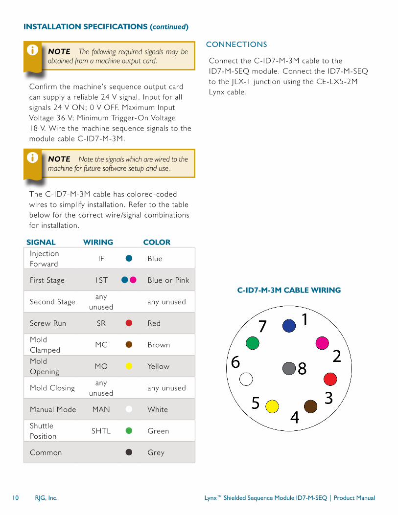
NOTE The following required signals may be obtained from a machine output card.
Confirm the machine’s sequence output card can supply a reliable 24 V signal. Input for all signals 24 V ON; 0 V OFF. Maximum Input Voltage 36 V; Minimum Trigger‑On Voltage 18 V. Wire the machine sequence signals to the module cable C‑ID7‑M‑3M.
NOTE Note the signals which are wired to the machine for future software setup and use.
The C‑ID7‑M‑3M cable has colored‑coded wires to simplify installation. Refer to the table below for the correct wire/signal combinations for installation.
SIGNAL WIRING COLORInjection Forward
IF Blue
First Stage 1ST Blue or Pink
Second Stageany
unusedany unused
Screw Run SR Red
Mold Clamped
MC Brown
Mold Opening
MO Yellow
Mold Closingany
unusedany unused
Manual Mode MAN White
Shuttle Position
SHTL Green
Common Grey
INSTALLATION SPECIFICATIONS (continued)
CONNECTIONS
Connect the C‑ID7‑M‑3M cable to the ID7‑M‑SEQ module. Connect the ID7‑M‑SEQ to the JLX‑1 junction using the CE‑LX5‑2M Lynx cable.
C‑ID7‑M‑3M CABLE WIRING

Product Manual | Lynx™ Shielded Sequence Module ID7‑M‑SEQ RJG, Inc. 11
MAINTENANCE
The shielded sequence module requires little to no maintenance provided that all installation instructions are followed.
CLEANING
REGULAR CLEANING
Cables must be installed in areas free from oil, dirt, grime, and grease.
RJG, Inc. recommends the following cleaners:
• Microcare MCC‑CCC Contact Cleaner C
• Microcare MCC‑SPR SuprClean™
• Miller‑Stephenson MS‑730L Contact Re‑Nu®
TESTING
Test the ID7‑M‑SEQ inputs after assignment using the Sequence Lights/Sequence Inputs tool in eDART version 9.xx software, or in Machine Setup/Test Inputs in eDART version 10.xx software, or util ize the integrated LED on the ID7‑M‑SEQ to verify that the corresponding light goes on/off for the machine sequence.
eDART VERSION 9.XX SOFTWARE
The Sequence Lights tool displays what stage of the process is taking place showing the on/off status of machine sequences. If a “light” is on, then the signal is on; if a “light is off, the signal is off. The Sequence Lights tool displays machine sequences that are not necessarily wired to the sequence module. To view the status of the hard‑wired sequence signals, select the Sequence Inputs inputs button on the Sequence Lights tool.
Similarly, the Sequence Inputs tool displays the hard‑wired signals statuses. With the machine in manual mode, cycle the machine while watching to verify that the corresponding “light” goes on/off for the machine sequence.
eDART VERSION 10.XX SOFTWARE
The Machine Setup/Test Inputs function displays the hard‑wired signal statuses. With the machine in manual mode, cycle the machine while watching to verify that the corresponding “light” goes on/off for the machine sequence.
WARRANTY
RJG, INC. STANDARD WARRANTY
RJG, Inc. is confident in the quality and robustness of the shielded machine interface modules, and so are offering a one‑year warranty. RJG’s products are guaranteed against defects in material and workmanship for one year from the original date of purchase. The warranty is void if it is determined that the adapter was subjected to abuse or neglect beyond the normal wear and tear of field use, or in the event the adapter box has been opened by the customer.
PRODUCT DISCLAIMER
RJG, Inc. is not responsible for the improper installation of this equipment, or any other equipment RJG manufactures.
Proper RJG equipment installation does not interfere with original equipment safety features of the machine. Safety mechanisms on all machines should never be removed.

Lynx™ Shielded Sequence Module ID7‑M‑SEQ | Product Manual12 RJG, Inc.

Product Manual | Lynx™ Shielded Sequence Module ID7‑M‑SEQ RJG, Inc. 13
TROUBLESHOOTING
COMMON ERRORS
SIGNAL ERRORS
1. Signal(s) do not appear on module test lights
Any signals that never appear “on” must be named “Not Used”, even if wired to the module. In eDART version 9.xx software Sensor Locations tool, assign the Sensor Location as “Not Used”. In eDART version 10.xx software Machine Setup/Inputs, the ID7‑M‑SEQ will automatically assign itself in the Sequence Signal (ID7) box; select the “i” to open the Locations selector, then select “Not Used” for a signal(s).
2. Signal(s) are unknown
If a signal does go on and off but is unknown, then name it “Unknown” and review it later (with the cycle graph or sequence lights functions).
Signals that have been assigned and have lights that go on and off at the wrong time must be corrected. In eDART version 9.xx software Sensor Locations tool, select the correct signal name. If none of the signal names listed correlate to the signal, then select “Not Used” (or “Unknown” to review it later).
3. Injection forward signal
On some machines the injection forward signal may not perform as specified; the eDART sequencer can adjust for some of these abnormalities. For example, if the screw run signal is available it will reject additional injection forward on signals until after the screw stops.
With other problems, such as a half‑second variation of the start of injection signal from shot to shot, or signal “bounce” at the beginning that causes the eDART to read the injection forward was on for a quarter of a second.
In eDART software version 9.xx, use the “Sequence Settings” “Injection” page:
• If the start of the signal is unreliable, select the “Ignore Injection Forward Sequence Module Input at Start”. The eDART will use screw motion (or injection pressure, if no screw) to determine the start.
• If the end of injection is not stable, or does not go off at the end of injection, select the “Ignore Injection Forward Sequence Module Input at End”. The eDART will use the fall ing pressure (corner or threshold) to determine where injection ends.
• If no Screw Run signal is available, then the “Ignore Injection Forward OFF→ON” setting may need to be adjusted if the injection forward signal comes on twice. Set the “ignore” time long enough so that the eDART does not detect the second event.
Each of these settings are saved with the machine; the settings only have to be applied once on a machine and are saved with the setup.

Lynx™ Shielded Sequence Module ID7‑M‑SEQ | Product Manual14 RJG, Inc.
ACCEPTABLE SIGNAL SUBSTITUTIONS
1. No injection forward signal
If the injection forward signal is not available the eDART uses several techniques determine when injection forward is on. In lieu of an injection forward signal, the following may be used as a substitute (in descending order of quality):
• Wired and assigned first stage or second stage sequence input signals
• Screw motion forward/fall ing edge of injection pressure (detected by eDART)
• Screw motion forward/screw motion backward for a time (detected by eDART)
• Injection pressure thresholds (detected by eDART)
• Mold clamped plus a set time to turn on and a set injection forward on time (detected by eDART)
2. No mold closed/clamped signal
If no mold closed/clamped signal is available, but both mold opening and mold closing are available, then the sequencer will create the mold closed/clamped signal from those two. It will use the end of mold closing for mold closed/clamped on and the start of mold opening for mold closed/clamped off.
3. No machine‑in‑manual signal
If a machine‑in‑semi‑auto mode or machine‑in‑auto mode signal is hard‑wired and assigned, then the sequencer inverts it and creates an internal machine‑in‑manual mode signal.
4. No screw run signal available
If no screw run signal is available, refer to the eDART version 9.xx or eDART version 10.xx software manuals for more information and instructions for screw run setup.
Product Manual | Lynx™ Shielded Sequence Module ID7‑M‑SEQ RJG, Inc. 15
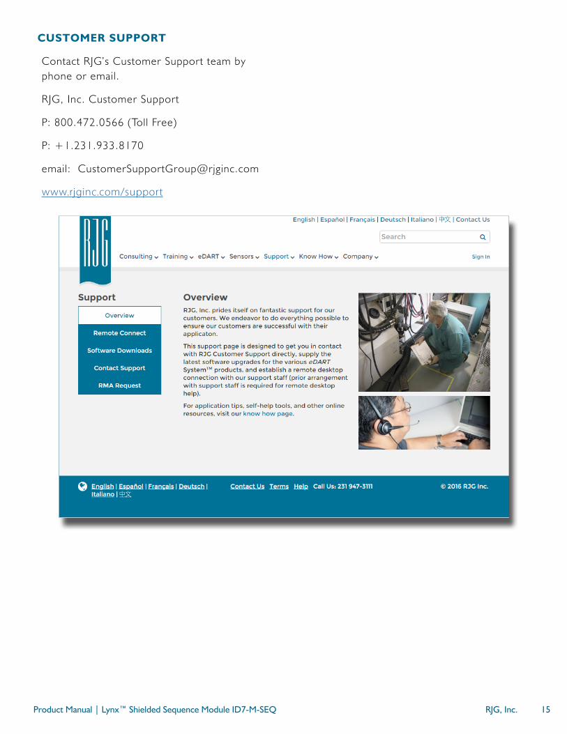
CUSTOMER SUPPORT
Contact RJG’s Customer Support team by phone or email.
RJG, Inc. Customer Support
P: 800.472.0566 (Toll Free)
P: +1.231.933.8170
email: [email protected]
www.rjginc.com/support

Lynx™ Shielded Sequence Module ID7‑M‑SEQ | Product Manual16 RJG, Inc.

Product Manual | Lynx™ Shielded Sequence Module ID7‑M‑SEQ RJG, Inc. 17
RELATED PRODUCTS
The shielded sequence module is compatible with other RJG, Inc. products for use with the eDART process control and monitoring system.
COMPATIBLE PRODUCTS
SHIELDED SEQUENCE MODULE CABLE C‑ID7‑M‑3M
The shielded sequence module cable C‑ID7‑M‑3M ( 1 at right) cable features a metal sheathing and shielding suited for the heat and stress found in injection molding environments. Designed specifically for use with RJG, Inc.’s machine sequence module ID7‑M‑SEQ and the eDART System, the C‑ID7‑M‑3M provides a connection from molding machines’ sequence output card and the RJG, Inc. ID7‑M‑SEQ.
1
2
3
LYNX CABLES CE‑LX5
The Lynx sensor cable ( 2 at right) is a polypropylene‑coated cable suited for the heat and stress found in injection molding environments. The cable is available in lengths 11.8–472.4” (0,3–12 m), and can be ordered with straight or 90° fittings. One CE‑LX5 is required to interface the ID7‑M‑SEQ with the eDART system.
eDART PROCESS CONTROLLER
The eDART process controller ( 3 at right) is the base hardware unit for the eDART system. The eDART system is the most powerful process control system in the industry, allowing molders to stabilize and control injection molding processes and contain bad parts, ensuring high quality and cost‑reduction.

Lynx™ Shielded Sequence Module ID7‑M‑SEQ | Product Manual18 RJG, Inc.
SIMILAR PRODUCTS
The following products, similar to the ID7‑M‑SEQ, are compatible for use with the eDART process control and monitoring system.
LYNX COMMUNICATIONS ADAPTER DIN/LX‑D
The Lynx communications adapter DIN/LX‑D ( 1 at right)is a shielded, DIN‑rail‑mounted module that interfaces other RJG, Inc. shielded machine interface modules with the eDART system when the ID7‑M‑SEQ is not used. This module is shielded to ensure high quality data even in rugged molding environments, and designed to be mounted on standard 35 mm DIN rails often found in machine panels.
LYNX SHIELDED DUAL‑RELAY OUTPUT MODULE OR2‑M
The Lynx shielded dual‑relay output module OR2‑M ( 2 at right) is a shielded, DIN‑rail‑mounted module that interfaces the eDART and sorting equipment or injection molding machines to implement part containment or control transfer. This module is shielded to ensure high quality data even in rugged molding environments, and designed to be mounted on standard 35 mm DIN rails often found in machine panels.
LYNX SHIELDED ANALOG INPUT MODULE IA1‑M‑V
The Lynx shielded analog input module IA1‑M‑V ( 3 at right)is a shielded, DIN‑rail‑mounted module that interfaces the eDART and injection molding machines in order to collect 0–10 V DC signals from analog measurement devices, providing information such as: injection pressure, plastic pressure, screw position, and temperature.
1
2
3


LOCATIONS / OFFICES
USA RJG USA (HEADQUARTERS)3111 Park Drive Traverse City, MI 49686 P +01 231 947‑3111 F +01 231 947‑6403 [email protected] www.rjginc.com
ITALY NEXT INNOVATION SRL Milano, Italy P +39 335 178 4035 [email protected] it.rjginc.com
MEXICO RJG MEXICOChihuahua, Mexico P +52 614 4242281 [email protected] es.rjginc.com
SINGAPORE RJG (S.E.A.) PTE LTD Singapore, Republic of Singapore P +65 6846 1518 [email protected] en.rjginc.com
FRANCE RJG FRANCEArnithod, France P +33 384 442 992 [email protected] fr.rjginc.com
CHINA RJG CHINA Chengdu, China P +86 28 6201 6816 [email protected] zh.rjginc.com
GERMANY RJG GERMANYKarlstein, Germany P +49 (0) 6188 44696 11 [email protected] de.rjginc.com
KOREA CAEPRO Seoul, Korea P +82 02‑2113‑1870 [email protected] www.caepro.co.kr
IRELAND/UK RJG TECHNOLOGIES, LTD. Peterborough, England P +44(0)1733‑232211 [email protected] www.rjginc.co.uk


