Page 1
PDH Star | T / F: (833) PDH‐STAR (734‐7827) | E: [email protected]
M‐050 Instruments and Devices for Boiler Control Systems Instructor: J. Paul Guyer, P.E., R.A. Course ID: M‐050 PDH Hours: 3 PDH
Page 2
J. Paul Guyer, P.E., R.A. Editor Paul Guyer is a registered civil engineer, mechanical engineer, fire protection engineer, and architect with over 35 years of experience in the design of buildings and related infrastructure. For an additional 9 years he was a senior advisor to the California Legislature on infrastructure and capital outlay issues. He is a graduate of Stanford University and has held numerous national, state and local positions with the American Society of Civil Engineers, National Society of Professional Engineers, Architectural Engineering Institute and Architectural Engineering Institute. He is Fellow of ASCE, AEI and CABE (U.K.).
An Introduction to Instruments and Devices for Boiler Control Systems
Page 3
An Introduction to Instruments and
Devices for Boiler Control Systems
J. Paul Guyer, P.E., R.A.
Editor
The Clubhouse Press El Macero, California
Page 4
CONTENTS
1. INTRODUCTION
2. PANEL INSTRUMENTS
3. LOCAL DEVICES AND INSTRUMENTATION
4. RECOMMENDED BOILER INSTRUMENTATION
5. REFERENCES
This course is adapted from the Unified Facilities Criteria of the United States government, which are in the public domain, is authorized for unlimited distribution, and is not copyrighted.
Page 5
© J. Paul Guyer 2018 1
1. INTRODUCTION
1.1 PURPOSE AND SCOPE. This course provides an introduction to instruments
and devices for steam and hot water boilers and their control systems. This is not a
design manual; it is an introduction to the technology, instruments and devices for
boiler operation and control, only.
Page 6
© J. Paul Guyer 2018 2
2. PANEL INSTRUMENTS
2.1 GENERAL. This section covers instruments usually located on panels.
2.1.1 TYPES OF CONTROL PANELS. Boiler plant panels include panels for boiler
control, combustion safeguards, and the control of special equipment such as
electrostatic precipitators.
2.1.2 PANEL LOCATION. Panels may be located either in a control room or locally.
Both types of panels are covered in this section and are discussed below.
2.1.2.1 CONTROL ROOM PANELS. The control room is the preferred location for
panels. Locate as much of the plant instrumentation in the control room as practical.
The central location of panels will simplify both operation and maintenance. The control
room is also usually cleaner, has better temperature and humidity control, and has less
vibration than other plant locations. These conditions necessitate less stringent
instrument enclosure requirements and the instruments will last longer.
2.1.2.2 LOCAL PANELS. Local panels are located in the vicinity of the equipment that
they control. This can be either indoors or outdoors. The atmosphere can vary from
clean to dusty or corrosive. Local panels should be minimized since more time and
effort is required to access and monitor a large number of local panels than a centrally
located one. Restrict local panels to instrumentation that does not require continuous
attention and is used extensively for start-up and shutdown of the local equipment.
Locate the panel as close to the equipment as practical. Do not locate local panels in
front of any access panels or inspection plates where an operator may interfere with
boiler inspections or where an explosion may injure an operator. Provide a panel
designed for the environment. Furnish the panel with a rain hood for outdoor locations.
Avoid local wall mounted panels which are mounted flush with the wall. These panels
may allow wall condensate to enter. The panel should be a self-supporting box type if it
is not mounted integrally with the local equipment.
Page 7
© J. Paul Guyer 2018 3
2.1.3 LAYOUT. Good panel layout requires experienced personnel in panel design and
user drawing review. The layout depends on the type of instrumentation to be placed on
the panel and how it will be operated. For best results both the user and the designer
should agree on instrumentation arrangement on the various panels prior to start of
panel fabrication. Once the panel is in fabrication changes are expensive and should be
kept to a minimum. Provide a minimum of 10 percent spare panel space for the future
expansion of control room panels. Provide 1.52 to 1.83 meters (5 to 6 feet) access
clearance between the panel and the wall behind it when possible. Recommended
practices on control room and panel layout are defined by ISA-RP60.3, Human
Engineering for Control Centers.
2.1.4 CONSTRUCTION. The following applies to both control room and local panels.
2.1.4.1 ELECTRICAL COMPONENTS. Use solid state logic. Do not use relay logic
except where only a few logic steps are involved. Use items that have a long life and do
not have to be frequently replaced. A typical example is the use of neon bulbs instead of
incandescent bulbs for indicator lights. The neon bulbs have a longer life.
2.1.4.2 DISPLAYS. Use displays that are readily visible to the operator. This might
entail specifying LED instead of LCD, although LCD consumes less power.
2.1.4.3 LIGHTING. Provide switched vapor tight lights to illuminate the front of the
panel. Provide additional switched lights to illuminate the inside of the panel enclosure.
2.1.4.4 SERVICE OUTLETS. Provide ground fault interrupt (GFI) protected 120 VAC
duplex outlets within each panel enclosure section. Locate outlets not more than 6 feet
apart within each section.
2.1.4.5 STEELWORK. Fabricate enclosure panels from 3.04 millimeter (11 gauge
Page 8
© J. Paul Guyer 2018 4
(0.1196-inch)) or 3.18 millimeter (1/8-inch) steel plate. Reinforce the panels as required
for stiffness. Use 1.52 millimeter (16 gauge (0.0598-inch)) minimum steel plate for
doors. Slightly bevel or round all exposed edges. Larger panels are usually fabricated in
3.05 to 3.66 meter (10 to 12 foot) long sections. Make all joints vertical. Horizontal panel
joints are not acceptable. Use angle iron at each end of a section to make up vertical
butt joints. Preassemble the complete panel in the shop to check for accurate alignment
and surface matching. Panel joints passing through an instrument are not acceptable.
2.1.4.6 PREFABRICATION. Specify panels to be complete with all instruments
installed, piped, and wired. The only actions that should be necessary to place the panel
in service are to connect power, instrument signals, and instrument air supply.
2.2 INDIVIDUAL ITEM REQUIREMENTS
2.2.1 CONTROLLERS. Boilers use three types of controllers. These are digital (e.g.
microprocessor or computer based), analog, and pneumatic. Use the following
guidelines in selecting the type of controller to be used:
Use the type of controller that is the most economical and reliable.
For plants with many control loops use digital type of controllers.
For the expansion of existing controls within a plant use the existing
technology. This may be either digital, analog electronic, or pneumatic
controllers.
Use pneumatic controllers in hazardous areas.
Avoid use of pneumatic controllers in the control room.
When using digital control avoid depending on a single or a few control devices
for the entire plant without having a backup. A redundant controller might
not be required if only a single controller controls one loop. However, if a
single controller controls a large number of loops then provide redundancy
so that if the controller fails another controller will automatically take over.
Page 9
© J. Paul Guyer 2018 5
2.2.1.1 Process Controllers. Process controllers use one or several of the following
control modes:
On-off
Proportional
Integral (also called reset)
Derivative (also called rate)
Most digital controllers have all of the above control modes included. They are also
usually provided with anti-reset windup. Analog and pneumatic controllers often do not
include all three control modes or anti-reset windup.
2.2.1.1.1 CONTROL MODES. In general, use the following control modes for the
indicated control loop.
Flow -- Use proportional plus integral.
Level -- Use proportional plus integral.
Pressure and Temperature -- Use proportional plus integral. Use proportional
plus integral plus rate when the application requires a quick response
time.
2.2.1.1.2 TESTING. Recommended practices on tests to be conducted on digital
controllers are defined by ISA-RP55.1, Hardware Testing of Digital Process Computers.
2.2.1.1.3 CONTROLS. Provide a separate control station for each control loop when
using digital controls. Locate critical controls on the front of the panel. Provide the
following minimum controls.
Automatic/manual selection
Set point adjustment
Output signal adjustment when on manual control
Page 10
© J. Paul Guyer 2018 6
Alarm setting
2.2.1.1.4 ALARMS. Provide the following minimum alarms.
Controller failure
High-high alarm
High alarm
Low alarm
Low-low alarm
2.2.1.1.5 DISPLAYS. Provide each control station with the following minimum displays.
Process reading
Set point
Output signal
Input signal
Automatic/Manual indication
Controller failure indication
High-high alarm
High alarm
Low alarm
Low-low alarm
2.2.1.1.6 FEATURES. Provide the following features as a minimum.
Proportional, integral and derivative control modes
Anti-reset windup
Automatic/manual and manual/automatic bumpless transfer
Change configuration without shutting down the control loop
Page 11
© J. Paul Guyer 2018 7
Display configuration data without interfering with the operation of the
controller.
2.2.1.1.7 Failure Response. Provide the following minimum actions on controller
failure.
The controller should switch to manual operation, hold its last output signal, and
send out an alarm showing controller failure if a backup controller is not
provided.
The control should automatically switch over to the backup controller and send
out an alarm showing controller failure if a backup controller is provided.
2.2.1.1.8 SIGNAL INTERFACE. Digital controllers do not always have dedicated
contacts for alarms and shutdowns. If the contacts are not provided, specify a controller
where dedicated contacts for each alarm and shutdown condition can be easily added
using hardware obtainable from the controller manufacturer. Provide one set of single
pole double throw (SPDT) contacts as a minimum.
2.2.1.2 PROGRAMMABLE LOGIC CONTROLLERS. Programmable logic controllers
(PLCs) are usually programmed in the electrical ladder diagram format. Other formats
are also used. When specifying PLCs include the following features.
Provide a controller that can be programmed in the electrical ladder diagram
format when many logic steps are involved.
Include provisions so that the controller can be programmed and the program
read without disturbing its operation.
2.2.1.3 CONTROLLER CONFIGURATION. Provide a controller that can be
programmed in any of the following ways at the programmer’s option.
From the front of the controller if a separate controller is provided
Page 12
© J. Paul Guyer 2018 8
From a manual control station if a separate controller is not provided
From a configuration device manually
From a configuration device using stored information from a tape, computer
disk, or other data storage device provide either a non-volatile memory or
battery back-up for the controller so that the controller configuration
memory is not lost due to a power outage.
2.2.2 RECORDERS. Keep recorders to a minimum. They constitute considerable
expense in paper and pen replacement costs. If recorders are required then standardize
them so as to keep paper and pen inventory costs to a minimum. Note that recorders
from different manufacturers usually require different paper and pens. The preferred
method of recording data is on computer disks, tapes, or other data storage device. This
data can later be viewed on a monitor, printed, or plotted.
2.2.3 TOTALIZERS. Provide a 8-digit minimum totalizer. Provide a lock to inhibit the
reset function of reset type totalizers. Whenever practical, record the data on a
computer disk, tape, or other permanent data storage device and use a computer
program to add up the totals.
2.2.4 INDICATORS. Dedicated indicators are commonly used with pneumatic and
analog type of control systems. Do not specify a dedicated indicator except for critical
items when using digital type control systems. Obtain non-critical information from a
control station readout or from a monitor.
2.2.5 STATUS LIGHTS. When dedicated status lights are required, use neon rather
than incandescent lights as much as practical. Neon lights have lo wer power
consumption and longer life. Use "Push to Test" indicating/status lights to ensure lights
are functioning properly. Obtain the information from a control station read-out or from a
monitor whenever practical instead of using status lights for digital type control systems.
Page 13
© J. Paul Guyer 2018 9
2.2.6 ANNUNCIATORS. Annunciator standards are defined by ANSI/ISA-S18.1,
Annunciator Sequences and Specifications. Use common trouble alarms instead of
dedicated alarms as much as practical. Provide both visual and audible alarms. Provide
a dedicated alarm for critical items.
2.2.6.1 COMMON ALARMS. Provide a dedicated window to contain the common
trouble alarms. When possible, include on this display the specific item within the group
that caused the alarm.
2.2.6.2 DEDICATED ALARMS. Provide a separate window that includes all dedicated
alarms associated with an area. Typical dedicated alarms are summarized in Table 4-2.
2.2.6.3 ANNUNCIATOR SYSTEMS. Include the following minimum items in an
annunciator system.
Solid-state electronic system with first-out sequence.
Back-lighted windows.
Acknowledge, test, and reset pushbuttons. Locate the pushbuttons outside of
the annunciator cabinet so that the cabinet door does not have to be
opened to depress the pushbuttons. Provide a separate audible signal
device and separate pushbuttons for each annunciator system.
2.2.6.4 ALARM INDICATIONS. The alarm indication is controlled by the annunciator
manufacturer. Typical indications for various fault conditions follow.
Normal - Light off and audible alarm off
Abnormal - Light flashing, audible alarm on
Abnormal First Out - Same as above except flashing pattern is different to
distinguish it as a first out.
Acknowledge - Audible alarm off
Other than first-out - Light steady
Page 14
© J. Paul Guyer 2018 10
First-out - Light flashing but pattern is different from prior to acknowledgment
Return to Normal - Light off and audible alarm off
2.2.7 SELECTOR SWITCHES. Provide a minimum of SPDT contacts for selector
switches. Clearly label all switch positions. Label unused positions as such. Use
backlighted switches for critical items in areas that are not well lit. Momentary selector
switches may be required to electrically sequence equipment to start on emergency
diesel generator power following the loss of normal power. This is necessary so as not
to overload the emergency power circuit with equipment that has selector switches
maintained in the "Run" mode.
2.2.8 PUSHBUTTONS. Use SPDT contacts as a minimum. Provide recessed or
covered pushbuttons for shutdowns to guard against nuisance trips.
2.2.9 PLANT CONTROL STATIONS. Plant control stations, like panels, can be located
either in a main control room or locally. The main control room is the preferred location.
Restrict local plant control stations to equipment that require them for start-up or
shutdown. In this case locate the control station as close to the equipment as practical.
A typical control station consists of a computer for processing and storing data, a
monitor, a keyboard, and a printer. Each of these items is discussed below.
2.2.9.1 COMPUTERS. Furnish the computer with a power supply that provides power
that is free of disturbances. The manufacturer should be able to provide power supply
specifications and recommend safeguards against severe power disturbances.
2.2.9.1.1 CONTROL LIMITS. Limit the ability of the computer to control the plant to
those functions that can be safely controlled from the computer and in compliance with
applicable codes. Provide an alarm connected to an annunciator to show computer
malfunction.
Page 15
© J. Paul Guyer 2018 11
2.2.9.1.2 DATA OVERFLOW ALARM. Provide computers that are used for logging
data with an alarm connected to an annunciator to show the following.
Data storage capacity is approaching full.
Data storage capacity has been exceeded.
2.2.9.1.3 REDUNDANCY. Provide a spare computer to automatically take over the
logging of critical data in the event of primary computer malfunction.
2.2.9.2 MONITORS. Cathode-ray tube (CRT) monitors are the most commonly used
type. Others include LCD type and luminous gas plasma screen type. Provide a spare
monitor that can be readily switched over to display critical data in the event that the
primary monitor malfunctions.
2.2.9.3 KEYBOARDS. Provide sealed-type keyboards to resist liquid spills. Keyboards
can be either a standard type or a non-standard with specialized keys. Standard
keyboards should be used as much as practical. Mistakes are more likely to be made
using a non-standard keyboard than using a standard keyboard. Keyboard replacement
is also more difficult with a non-standard type.
2.2.9.4 PRINTERS AND PLOTTERS. Provide an alarm connected to an annunciator to
show printer failure for printers receiving critical on-line data. Also provide a back-up
printer to take over if the primary printer malfunctions.
2.2.10 DATA LOGGING. Provide the following minimum data logging for digital type
control systems. Print out this information automatically on a dedicated printer.
Date, time, and device alarmed or shut down
Identify first out
Time alarm acknowledged
Time for return to normal
Page 16
© J. Paul Guyer 2018 12
Include year, day, hours, minutes, and seconds in the date and time. In first
out, show the device to alarm first then the device to first shut down the equipment.
2.2.11 RECEIVER INSTRUMENTS. These instruments include recorders, indicators,
controllers and totalizers (also known as integrators). Each is covered separately in
preceding paragraphs.
2.2.12 POTENTIOMETER INSTRUMENTS. These instruments include recorders,
indicators, controllers and transmitters.
Page 17
© J. Paul Guyer 2018 13
3. LOCAL DEVICES AND INSTRUMENTATION
3.1 GENERAL. This discussion covers local instruments. Panel instruments are not
included. Instruments that are usually located on panels, such as controllers, are
covered above. Instruments should be located where they are accessible. Instruments
that must be operated during the start-up or shutdown of equipment should be located
as close to the equipment as practical. Some instruments must be accessed
continuously for operation, others only during startup and shutdown. All instruments
must be accessible for calibration and maintenance. Locate instruments using the
following order of access preference.
Grade
Platform
Stairs
Ladder
Portable ladder
3.2 INDIVIDUAL ITEM REQUIREMENTS
3.2.1 VALVES. This paragraph covers control valves, pressure regulators and solenoid
valves. Each type is discussed below.
3.2.1.1 CONTROL VALVES. Common types of flow characteristics for control valves
include quick opening, linear, and equal percentage. Control valves with equal
percentage flow characteristics are specified for most applications. Control valves with
linear flow characteristics are hard to tune at low flow and should be avoided. Select the
flow characteristic to suit the application. Tolerance criteria for control valves are
defined by ISA-S75.11, Inherent Flow Characteristics and Rangeability of Control
Valves.
Page 18
© J. Paul Guyer 2018 14
3.2.1.1.1 DESIGN CHECKLIST. There are many items to be considered in control valve
selection. Checklists are provided in most manufacturer catalogs. Critical items that are
sometimes overlooked include type of shutoff, shutoff pressure, line hydrotest pressure
and controllability at turndown conditions. Review all pertinent sizing and selection
information including accessories when selecting a control valve.
3.2.1.1.2 CONSTRUCTION. Use carbon steel body with stainless steel trim. Other
materials may be specified when required by unique conditions.
3.2.1.1.3 SIZING. Size control valves to absorb 30 to 50 percent of the total system
pressure drop.
3.2.1.1.4 MAINTENANCE. Provide manual block and bypass valves around control
valves where practical to allow for control valve removal and servicing while the system
is operational. If a manual bypass is not provided then furnish the valve with a hand
wheel.
3.2.1.1.5 LOCATION. Locate control valves at grade where practical. Install the control
valve near the operating equipment that has to be observed while in local manual
control.
3.2.1.2 PRESSURE REGULATORS. Use self-actuated regulators only where the
operating pressure is below 10.34 bar (150 psig) and where variations from the control
point are acceptable. Use pilot-operated pressure regulators where the operating
pressure is equal to or above 10.34 bar (150 psig), or where minimal variations from the
control setpoint are acceptable.
3.2.1.3 SOLENOID VALVES. Common uses for solenoid valves in a boiler plant include
the routing of instrument air to control devices and shutoff service. Verify solenoid valve
sizing to ensure that the valve or damper will open or close within the specified amount
of time. Port size might have to be increased to ensure the proper actuation time. Verify
Page 19
© J. Paul Guyer 2018 15
that the proper solenoid valve is used for the intended service. An example of a critical
service application is a pilot gas shutoff solenoid valve. Most manufacturer catalogs
include checklists on items to be specified. Critical items sometimes overlooked include
type of fluid, shutoff and opening pressures, and line test pressure.
3.2.2 ACTUATORS. Use spring-loaded diaphragm type actuators where practical.
Springless operators and cylinder operators are acceptable only when spring-loaded
diaphragm type actuators cannot provide the desired performance. Select the actuator
so that the valve or damper that it controls will fail safe. Fail safe is defined as lock in
position or take a position (either open or closed) that will result in the least upset.
Furnish a pressure gauge to show diaphragm loading pressure on actuators that do not
have a positioner. Furnish positioners for all automatically operated dampers. Furnish
positioners for all control valves in critical service and where the variable, such as flow,
has to be closely controlled. Specify that the positioner be furnished with the control
valve or damper instead of separate procurement. Provide bypass switches and 3
pressure gauges (air supply, instrument loading, and diaphragm pressure) for all
positioners.
3.2.3 CURRENT TO PNEUMATIC CONVERTERS. Control valves and dampers require
current to pneumatic converters (I/Ps) for pneumatic actuators with electronic control
signals. It is important that the I/P be matched to the valve or damper, as applicable. To
avoid possible mismatch have the I/P furnished with the valve or damper instead of
separate procurement.
3.2.4 DAMPERS. Dampers can be operated either manually or by means of an
actuator. This paragraph covers only actuator-operated dampers. Manually operated
dampers are not included in this document. Specify temperature, pressure, pressure
drop, type of shutoff, materials, damper bearings, linkages, damper bearing and linkage
lubrication, and other applicable data when selecting dampers. Provide a hand wheel or
lever so that the damper can be manually operated in case of damper actuator failure.
Page 20
© J. Paul Guyer 2018 16
3.2.5 PRESSURE RELIEF VALVES. Provide pressure relief valves in accordance with
the applicable codes.
3.2.6 RUPTURE DISKS. Use reverse buckling type rupture disks at the inlet of the relief
valve in corrosive services.
3.2.7 LEVEL INSTRUMENTS. Provide level instruments in accordance with applicable
codes. In general, provide separate vessel connections for each level instrument.
Provide 12.7 millimeter (½ -inch) minimum vent and drain valves with plugs for all level
instruments.
3.2.7.1 GAUGE GLASSES. Complete coverage of total liquid range is not always
required. Consult the applicable codes for requirements. Also consider all operating
conditions and upsets. Provide gauge glasses to cover and overlap a minimum of 5.08
centimeters (2 inches) beyond the ranges of displacers and switches. Gauge glasses
should only cover the critical range zone such as high, low, and normal levels when the
range is also covered by differential pressure type level transmitters. Provide
illuminators for transparent gauge glasses.
3.2.7.2 DISPLACER. Displacer type level instruments can be used for level ranges up
to 1.52 meters (60 inches) of fluid height. Avoid use of internal displacers except for
open tanks and sumps. Provide carbon steel body material with stainless steel trim as a
minimum.
3.2.7.3 DIFFERENTIAL PRESSURE. Use differential pressure type level instruments
instead of displacer type level instruments for ranges over 1.52 meters (60 inches) of
fluid height. They may also be used for ranges under 1.52 meters (60 inches).
3.2.7.4 CAPACITANCE LEVEL. Avoid the use of capacitance type level instruments in
boiler plants.
Page 21
© J. Paul Guyer 2018 17
3.2.8 FLOW INSTRUMENTS. The most commonly used flow element in boiler plants is
the orifice plate. There are numerous other flow measuring devices that can be used
depending on the application. In alphabetical order these include annubar flowmeters,
coriolis type mass flowmeters, elbow meters, flow nozzles, magnetic flowmeters, pitot
tubes, pitot-venturi tubes, positive displacement meters, rotameters, target meters,
thermal-loss meters (also known as heat-loss meters), turbine meters, ultrasonic
flowmeters, venturi tubes, vortex flowmeters, and wedge elements. Use an orifice plate
for most flow measurement applications unless a different type of flow element, such as
a flow nozzle or a pitot tube, offers specific advantages. Reasons for using flow
elements other than orifice plates include higher accuracy, shorter meter run, lower
pressure drop and large line size.
3.2.8.1 METER RUNS. Flow disturbances as much as 100 pipe diameters upstream of
the flow measuring element can affect the accuracy of the flow measurement. Meter run
requirements, including pressure tap locations, depend on a number of items. These
include type of flow element, beta ratio, and flow disturbances upstream and
downstream of the flow element. Flow disturbances result from valves, elbows,
enlargers, reducers, and other pipe fittings.
3.2.8.1.1 REQUIREMENTS. Obtain complete meter run requirements from the flow
measuring device manufacturer to insure accurate measurements. This includes
pressure tap locations and other details such as pressure tap size.
3.2.8.1.2 STRAIGHTENING VANES. Avoid the use of straightening vanes due to their
cost. Use them only when meter runs without them are not practical.
3.2.8.1.3 FABRICATION. Do not fabricate meter runs in the field. Fabricate them in a
shop qualified in that type of work. Include in the shop fabricated meter run at least 10
pipe diameters of upstream piping and 5 pipe diameters of down stream piping. Straight
runs of piping required in addition to the above can be fabricated in the field.
Page 22
© J. Paul Guyer 2018 18
3.2.8.2 ORIFICE PLATES. Orifice plate types include concentric and eccentric, square
edge, quadrant edge, segmental and annular. In general, use concentric, square-edge
orifice plates except for the following.
Use quadrant edge for orifice plates with a Reynolds number of less than
10,000 (based on pipe diameter).
Do not use concentric orifice plates for horizontal runs flowing wet steam or
gas, liquids containing solids, or liquids containing gas or vapor. All of the
above will result in inaccurate measurements.
Water in the wet steam and liquid in the wet gas can cause damming of the
liquid. Solids in the liquid can settle out upstream of the orifice plate. As a
first solution use a concentric, square-edge orifice plate but locate it in a
vertical run with flow in the downward direction. If locating the orifice plate
in a horizontal run cannot be avoided then use a segmental or eccentric
orifice plate.
Use a concentric, square-edge orifice plate located in a vertical run with flow in
the upward direction for liquids containing gas or vapor. Use a segmental
or eccentric orifice plate with the opening at the top if locating the orifice
plate in a horizontal run cannot be avoided.
3.2.8.2.1 DESIGN. Meter runs should be a minimum pipe diameter of 5.08 centimeters
(2 inches). Do not use an orifice bore diameter of less than 12.7 millimeters (0.5 inch)
due to the possibility of plugging. Do not locate orifices where a liquid is subject to
flashing. Select the orifice plate maximum design flow and meter differential to give a
scale reading of approximately 70 percent at normal flow. Use a meter differential of
2.54 meters (100 inches) of water unless not practical. The orifice plate beta ratio
should be between 0.25 and 0.70 and preferably between 0.4 and 0.6. The beta ratio
must never be less than 0.20. Do not exceed a beta ratio of 0.70 for gases or steam and
0.75 for liquids.
Page 23
© J. Paul Guyer 2018 19
3.2.8.2.2 MOUNTING. Mount the transmitter near the orifice flanges. Use flange taps
whenever practical. Specify orifice flange and taps in accordance with ASME B16.36,
Orifice Flanges. Flange taps are well suited for pipe sizes of 5.08 centimeters (2 inches)
and larger. Provide meter taps at the top of the flange for gas service in horizontal lines.
Provide meter taps on the sides of the flange for steam, vapor and liquid service in
horizontal lines. Mount the meter below the orifice taps for liquid and steam service and
above the orifice taps for gas service. Provide a separate three valve type manifold for
each meter. Provide condensate traps for both the high and low pressure sensing lines
for steam and condensate service lines.
3.2.8.2.3 CONSTRUCTION. Use 304SS material as a minimum for the orifice plate.
Provide an identification tab projecting beyond the orifice flange. Show the following
minimum information on the tab.
Actual measured orifice bore
Pipe inside diameter
Orifice plate material
Orifice plate orientation to flow
Type of fluid
3.2.8.3 FLOW NOZZLES. Use flow nozzles for applications where a higher accuracy is
required than using orifice plates.
3.2.8.4 VENTURI TUBES. Use venturi tubes for applications where higher accuracy,
lower pressure drop and shorter meter run are required than using orifice plates or flow
3.2.8.5 ELBOW METERS. Elbow meters may be used for measuring relative flow rates
and where absolute readings are not required. Elbow meters provide good repeatability
and can be installed using an elbow in the regular piping.
Page 24
© J. Paul Guyer 2018 20
3.2.8.6 PITOT TUBES. Use pitot tubes for large ducts where high accuracy and
rangeability are not required and where pressure drops must kept low.
3.2.8.7 ROTAMETERS. Rotameters are used for flow measurement in small lines such
as fuel oil and purge air. Use glass tube rotameters only for purge air. Otherwise use
armored type rotameters. Recommended practices on rotameters are defined by ISA-
RP16.1, 2, 3, Terminology, Dimensions and Safety Practices for Indicating Variable
Area Meters (Rotameters, Glass Tube, Metal Tube, Extension Type Glass Tube), ISA-
RP16.4, Nomenclature and Terminology for Extension Type Variable Area Meters
(Rotameters), and ISA-RP16.5, Installation, Operation, Maintenance Instructions for
Glass Tube Variable Area Meters (Rotameters).
3.2.8.8 MAGNETIC FLOWMETERS. Magnetic flowmeters provide obstructionless flow,
good accuracy, and a good turndown ratio. They have the disadvantage, however, of
being costly, large, and heavy.
3.2.8.9 POSITIVE DISPLACEMENT METERS. Use positive displacement meters only
for high accuracy totalizing where measurement of flow rate is not required. These
meters would typically be used for the measurement of fuel oil, fuel gas, and feedwater
flow. Furnish a removable strainer installed upstream of the displacement meter.
3.2.8.10 TURBINE METERS. Turbine meters are extremely accurate and have a high
turndown ratio. They do, however, present a high pressure loss to the system. Refer to
ISA-RP31.1, Specification, Installation, and Calibration of Turbine Flowmeters for
additional information on turbine meters.
3.2.8.11 VORTEX METERS. Vortex meters are extremely accurate, have a high
turndown ratio, and present a low permanent pressure loss to the system.
3.2.8.12 ANNUBAR METERS. An annubar meter is a rigid tube device that measures
flow by producing a pressure drop signal that is proportional to the square of the flow
Page 25
© J. Paul Guyer 2018 21
rate. Multiple sensing ports along the tube average the velocity profile of the fluid.
Meters of this type provide less permanent system pressure drop than orifice plates and
can be used for all applications that involve clean fluids. Measurement accuracy and
repeatability is good and turndown ratios of 4:1 to 11:1 can be achieved depending on
meter tube design.
3.2.9 TEMPERATURE MEASUREMENTS. Temperature instruments include
thermocouples, resistance-temperature detectors (RTDs), filled bulb systems, and
bimetallic thermometers.
3.2.9.1 THERMOWELLS. Thermowells are used to protect the temperature element
from the environment and for personnel protection. Thermowell design varies
depending on the application. Items affecting design include temperature, pressure,
type of fluid and fluid velocity. In general, thermowells can be classified into two types.
These are pressure service and non-pressure service. Thermowells used in
nonpressure service are commonly referred to as protective tubes.
Provide thermowells for all temperature elements in pressure service. Use 304 SS
material as a minimum. Use the material best suited for the application of protective
tubes.
3.2.9.2 THERMOCOUPLES. In general, use the following thermocouples for the
different temperature ranges:
Type T, Copper constantan -- Below –17.77 to 371 degrees C (0 to 700
degrees F)
Type J, Iron constantan -- -17.77 to 593 degrees C (0 to1,100 degrees F)
Type K, Chromel alumel -- 315 to 1093 degrees C (600 to 2,000 degrees F)
Thermocouple assemblies can be single (one thermocouple) or duplex (two
thermocouples). Provide duplex thermocouples for all temperature control loops. Use
Page 26
© J. Paul Guyer 2018 22
one thermocouple for control and the other for indication. Thermocouple and
thermocouple extension wire specifications are defined in ANSI/ISA-MC96.1,
Temperature Measurement Thermocouples, and NEMA-WC55, Instrumentation Cable
and Thermocouple Wire.
3.2.9.3 RESISTANCE-TEMPERATURE DETECTORS. Resistance-temperature
detectors (RTDs) are used where accurate temperature or temperature difference
measurements are required.
3.2.9.4 FILLED BULB SYSTEMS. Filled bulb systems are used for local temperature
indicators, recorders, and controllers in services where the fluid temperature is below
426 degrees C (800 degrees F). Mercury filled bulb systems are not allowed. Provide
armored capillary tubing for all filled bulb systems. Limit capillary length to 15.24 meters
(50 feet) maximum. In all cases provide a thermowell where the filled bulb system is
used in pressure service.
3.2.9.5 BIMETALLIC THERMOMETERS. Bimetallic thermometers are mostly dial type
thermometers used for local temperature indication. In all cases provide a thermowell
where the bimetallic thermometer is used in pressure service.
3.2.10 PRESSURE MEASUREMENTS. Pressure instruments include gauges,
switches, and transmitters. In general pressure gauges use bourdon tubes to measure
pressure greater than 1.03 bar (15 psig), and bellows to measure pressure less than
1.03 bar (15 psig) or differential pressure. Transmitters and switches use diaphragms to
measure pressure. Use snubbers where pulsation dampening is required.
3.2.10.1 GAUGES. Provide blowout discs for pressure gauges in services with
pressures greater than 1.03 bar (15 psig). Provide a safety wall between the dial and
the bourdon for service pressures above 68.9 bar (1000 psig). Provide pigtail siphons
for all gauges in steam service. Pigtail siphons should be installed perpendicular to the
gauge. Provide pulsation dampers and diaphragm seals where required by service
Page 27
© J. Paul Guyer 2018 23
conditions and for all gauges in steam and condensate service. Provide a gauge
isolation valve for each gauge. Pressure gauges are usually direct connected and field
mounted. The size and range is specified by the user. Locate local gauges so that they
are visible from the operating area and are readable from grade or a platform. Local
mounted gauges give a “backup” reading and also help operators in determining if
equipment or pressure systems are working satisfactorily. Pressure gauges should
conform to ASME B40.100, Pressure Gauges and Gauge Attachments.
3.2.10.2 SWITCHES. Pressure switches are used for monitoring alarm conditions and
providing safety shutdowns. They are typically mounted directly to the process pipe.
3.2.10.3 TRANSMITTERS. Pressure transmitters convert the measured pressure to an
analog or digital signal that is monitored by the control system (e.g. PLC). Provide a
three-valve manifold to accomplish block, drain, and test functions for all pressure
transmitters. Provide a five-valve manifold to accomplish block, equalize, drain, and test
functions for all differential-pressure transmitters. Refer to paragraph 5-2.11 for
additional transmitter requirements.
3.2.10.4 DRAFT. Pressure instruments for the measurement of draft in furnaces require
careful attention as to range and sizing. Note that the draft in a balanced draft boiler
furnace is slightly negative, around -2.54 millimeter (-0.1 inch) WC, at the top of the
furnace. Too wide an instrument range will result in the loss of accuracy. Too narrow a
range will not cover all operating conditions. Verify that the connections and sensing
lines are adequately sized for the low negative pressures. Use larger sizes than for lines
sensing positive and high pressures.
3.2.11 ELECTRONIC TRANSMITTERS. Electronic transmitters are used to transmit an
electronic signal from a local measuring device to a remotely located device such as a
panel mounted controller. Typical transmitters include flow, level, pressure and flue gas
oxygen. A typical electronic signal is 4-20 mA DC. Use stainless steel material for all
transmitter components in contact with the stream. Provide local indicators for all
Page 28
© J. Paul Guyer 2018 24
electronic transmitters. Locate the local indicator at the transmitter for non-controlling
loops such as a signal to an indicator or recorder. Locate the local indicator at the
controlling device for controlling loops such as diaphragm-operated valves. Provide an
integrally mounted junction box with a metal cover and a terminal block for blind
electronic transmitters to allow for the connection of a plug-in ammeter. Electronic
transmitters with internal microprocessors are known as “smart transmitters”. These
transmitters provide on-board sensor linearization, data correction coefficients,
measurement ranging, system diagnostics, and instrument configuration. These
transmitters communicate to the control system via a communication bus (e.g. HART or
Fieldbus).
3.2.12 ELECTRICAL INSTRUMENT SWITCHES. Typical applications for electrical
instrument switches are alarms and shutdowns. Contacts should open to alarm or shut
down for fail safe operation. Provide switches that are suited for the environment.
Provide switches that are dust tight and vibration proof for all locations. Provide NEMA
4 rated switches for outdoor locations with non-corrosive atmospheres and NEMA 4X
rated switches for corrosive atmospheres. Provide SPDT contacts as a minimum.
3.2.13 ANALYZERS. Include all analyzers necessary to meet federal, state, and local
environmental monitoring requirements. Analyzers used in a boiler plant include the
following:
In-line
Sample diverted from the stream to the analyzer and then returned to the
stream
Sample diverted from the stream to the analyzer and then discharged to the
atmosphere or a drain
3.2.13.1 GENERAL GUIDELINES. Use in-line analyzers where practical. As a second
choice use an analyzer where the sample is diverted to the analyzer and then returned
to the stream. Use an analyzer where the sample is discharged to the atmosphere or
Page 29
© J. Paul Guyer 2018 25
drain as a last choice. Provide a relatively constant differential pressure device, such as
a pump, as a bypass to divert a sample that is to be returned to the stream. Avoid
bypassing around a control valve.
3.2.13.1.1 CALIBRATION. Where practical use a self-calibrating analyzer that provides
zero and full span in the range in which the analyzer will be operating. Provide
automatic calibration at power-up, at manual command, and at preprogrammed
intervals.
3.2.13.1.2 APPLICATION. When to use analyzers and what type of analyzer to use
depends upon environmental and value engineering concerns for a given boiler size.
Analyzers should be used for trim or alarms. Avoid using analyzers as a sole means of
control or shutdown.
3.2.13.1.3 PACKAGING. It is possible to obtain multiple analyzers packaged in one
system. For example, flue gas analyzers are available that combine oxygen,
combustibles and methane measurement in one package. This packaging concept
would reduce installation complexity and may provide cost savings. When practical
obtain the analyzer from the manufacturer completely packaged in a housing, wired,
piped and with the sample system installed. Specify the analyzer to be free standing
unless it is mounted on the equipment.
3.2.13.2 OXYGEN ANALYZER. Oxygen analyzers in a boiler plant are used for oxygen
measurement to provide an indication of excess air in the flue gas. Use the analyzer for
alarms and trim. Do not use it as the sole instrument for the control of combustion air.
Probe location is not critical for forced draft type or pressurized boilers since leakage is
flue gas out of the boiler. Probe location is critical, however, for balanced draft boilers
(which have induced draft fans), since leakage is typically tramp air into the boiler from
flue ductwork. Locate the oxygen probe so as to keep the effect of tramp air on the
oxygen reading at a minimum. This usually entails locating the probe as close to the
furnace as practical.
Page 30
© J. Paul Guyer 2018 26
3.2.13.3 COMBUSTIBLES ANALYZER. Combustibles analyzers in a boiler plant are
used for carbon monoxide measurement, hydrogen measurement or both to provide an
indication of incomplete combustion in the flue gas. Use the analyzer for alarms and
trim. Do not use it as the sole instrument for the control of combustion air.
3.2.13.3.1 CARBON MONOXIDE ANALYZER. Carbon monoxide (CO) analyzers used
in a boiler plant may utilize a catalytic element, wet electrochemical cell, or non-
dispersive infrared absorption. Install the CO analyzer in a clean gas stream that is
downstream of the particulate removal system. A CO analyzer permits firing at lower
oxygen levels than without it. A minimum air requirement is established by decreasing
oxygen in the stack gas until a large increase in the CO reading occurs. A CO analyzer
is also useful in boiler startup. During start-up monitor the CO analyzer closely for
unsafe firing conditions. High CO readings indicate incomplete combustion, which
implies potentially unsafe conditions in the furnace.
3.2.13.3.2 HYDROGEN ANALYZER. Hydrogen (H2) analyzers used in a boiler plant are
on line monitors that employ a catalytic element. Like the CO analyzer, a Hydrogen
analyzer permits firing at lower oxygen levels than without it. A minimum air requirement
is established by decreasing oxygen in the stack gas until a large increase in the H2
reading occurs. A H2 analyzer is also useful in boiler start-up. During start-up monitor
the H2 analyzer closely for unsafe firing conditions. High H2 readings indicate incomplete
combustion, which implies potentially unsafe conditions in the furnace.
3.2.13.4 STACK OPACITY ANALYZER. Stack opacity analyzers are used in a boiler
plant to monitor particulate emissions. Their main use is in coal and heavy oil fired
boilers. Stack opacity monitors are generally not required for gas fired boilers, however,
state and federal regulations should be consulted. Also, most large boilers are dual fuel
which may be a combination of gas and oil.
Page 31
© J. Paul Guyer 2018 27
3.2.13.5 CONDUCTIVITY ANALYZERS. Conductivity analyzers are used in boiler
plants to monitor dissolved solids in the boiler drum. Use a conductivity analyzer for
adjusting boiler blowdown. Do not use it as the sole device for boiler blowdown control.
3.2.13.6 METHANE ANALYZERS. Methane analyzers in a boiler plant are used for
methane measurement to provide an indication of a completed purge cycle prior to
boiler ignition or during boiler shutdown. Note that this analyzer must be used in
conjunction with and not as a substitute for the minimum purge time requirements
stated in the applicable codes.
3.2.14 FLAME DETECTORS. Provide the flame detector best suited for the fuel and
flame. For gas fired boilers always use an ultraviolet (UV) self-checking flame scanner.
Do not use a flame detector that is activated by hot refractory. Provide a separate flame
detector for each burner. Locate the flame detector so that it will be activated only by its
own burner and not by an adjacent burner or hot refractory.
3.2.15 CONTINUOUS EMISSION MONITORING (CEM). Provide all necessary
equipment to meet federal, state, and local environmental analysis and documentation
requirements.
Page 32
© J. Paul Guyer 2018 28
4. RECOMMENDED BOILER INSTRUMENTATION
4.1 BOILER CONTROL PANEL INDICATORS, RECORDERS AND TOTALIZERS.
The instrumentation in Table 4-1 represents the minimum recommended requirements
for a boiler plant. This instrumentation selection is based primarily on boiler operation
safety concerns. Refer to NFPA 8502, Standard for the Prevention of Furnace
Explosions/Implosions in Multiple Burner Boilers for further instrumentation concerns for
boiler plants in the 13.18 gigajoule/h (12,500,000 Btu/h) or above range and ASME
CSD-1, Controls and Safety Devices for Automatically Fired Boilers for boiler plants
below 13.18 gigajoule/h (12,500,000 Btu/h). The indicators and recorders can be either
dedicated or shared devices. Totalizers must be dedicated devices. Shared device
selection may be either by means of pushbuttons, a selector switch, or by entering
commands on a keyboard. Provide the following in the display of information associated
with a shared device.
Name of process variable
Instrument number
Units
Process variable value
Store the process data in a storage device such as a computer disk or tape if a
dedicated recorder or totalizer is not provided. Label the computer disk or tape as to
process variable, instrument number, date, time, and units. The time label must include
hours, minutes, and seconds. Store the data so that it can be retrieved selectively. In
selective retrieval as a minimum include the name of process variable, instrument
number, date and desired time interval. Include maximum and minimum points and
alarms with the data to be recorded. Provide a dedicated printer or printer/plotter on
which the recorded and totalized data can be presented on paper on demand. Data
storage, retrieval, and printing must meet federal, state, and local environmental
documentation requirements. An instrumentation item is not applicable if the equipment
Page 33
© J. Paul Guyer 2018 29
Table 4-1
Boiler Control Panel Indicators, Recorders and Totalizers (X shows instrumentation item required)
Page 34
© J. Paul Guyer 2018 30
Table 4-1 (continued)
Boiler Control Panel Indicators, Recorders and Totalizers (X shows instrumentation item required)
that it services is not included in the plant. For example, if an air preheater is not
provided then an air preheater outlet temperature indicator does not have to be
furnished.
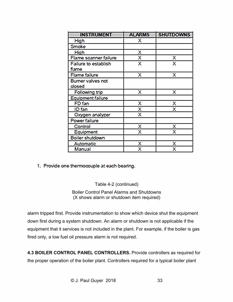
4.2 BOILER CONTROL PANEL ALARMS AND SHUTDOWNS. The alarms and
shutdowns in Table 4-2 represent the minimum recommended requirements for a boiler
plant. These were selected based primarily on boiler operation safety concerns.
Refer to NFPA 8502, Standard for the Prevention of Furnace Explosions/Implosions in
Multiple Burner Boilers for further information for boiler plants in the 13.18 gigajoule/h
(12,500,000 Btu/h) or above range and ASME CSD-1, Controls and Safety Devices for
Automatically Fired Boilers for boiler plants below 13.18 gigajoule/h (12,500,000 Btu/h).
Provide a separate window in an annunciator system for each dedicated alarm. Provide
a dedicated common trouble alarm window to which the non-dedicated alarms are
wired. Include a first-out listing to show which device connected to the common trouble
Page 35
© J. Paul Guyer 2018 31
Table 4-2
Boiler Control Panel Alarms and Shutdowns (X shows alarm or shutdown item required)
Page 36
© J. Paul Guyer 2018 32
Table 4-2 (continued)
Boiler Control Panel Alarms and Shutdowns (X shows alarm or shutdown item required)
Page 37
© J. Paul Guyer 2018 33
Table 4-2 (continued)
Boiler Control Panel Alarms and Shutdowns (X shows alarm or shutdown item required)
alarm tripped first. Provide instrumentation to show which device shut the equipment
down first during a system shutdown. An alarm or shutdown is not applicable if the
equipment that it services is not included in the plant. For example, if the boiler is gas
fired only, a low fuel oil pressure alarm is not required.
4.3 BOILER CONTROL PANEL CONTROLLERS. Provide controllers as required for
the proper operation of the boiler plant. Controllers required for a typical boiler plant
Page 38
© J. Paul Guyer 2018 34
include steam header pressure (plant master and boiler master), boiler drum water level
(feedwater flow), fuel flow, combustion air flow and boiler furnace draft.
4.4 VALUE ENGINEERING. There are many cost tradeoffs associated with the design
of a boiler. The use of an oxygen trim system is one example. The installation of an
oxygen trim system in a boiler design will provide fuel savings. The analyzer that
provides this function, however, is costly to buy and maintain. Therefore, oxygen trim
systems should only be used on large boilers where the cost of fuel savings outweighs
the cost of the analyzer.
Page 39
© J. Paul Guyer 2018 35
5. REFERENCES
Page 40
© J. Paul Guyer 2018 36
Page 41
© J. Paul Guyer 2018 37
Page 42
© J. Paul Guyer 2018 38