15
M-Bus Pulse Collector Twin-Pulse Instruction Manual Rev. 1 10/13
M-Bus Pulse Collector
Twin-Pulse
Instruction Manual
Rev. 1 10/13

Maddalena S.p.A.
Via G.B. Maddalena 2/4 – 33040 Povoletto – (UD) – Italy
Tel.: +39 0432/634811 Fax Export Dept.: +39 0432/679820
E-mail: [email protected] – www.maddalena.it

Contents
1 GENERAL DESCRIPTION .................................................................................................................................................. 1 1.1 TECHNICAL SPECIFICATIONS ................................................................................................................................................... 1 1.2 DEFAULT PARAMETERS ......................................................................................................................................................... 2 1.3 TWIN-PULSE INSTALLATION PROCEDURE .................................................................................................................................. 2
1.3.1 Module Activation .................................................................................................................................................. 2 1.3.2 Connections ............................................................................................................................................................ 2 1.3.3 Device Configuration .............................................................................................................................................. 3
1.4 RESETTING DEFAULT PARAMETERS ......................................................................................................................................... 3 1.5 DESCRIPTION OF THE TELEGRAM RSP_UD TRANSMITTED BY THE MODULE .................................................................................... 4 1.6 DESCRIPTION OF THE CONFIGURATION TELEGRAM SND_UD ....................................................................................................... 6
1.6.1 Example of Configuration Telegram ....................................................................................................................... 6 2 APPENDX A .................................................................................................................................................................... 7
2.1 DEVICE TYPE IDENTIFICATION TABLE (MEDIUM) .......................................................................................................................... 7 2.2 PRIMARY VIF'S (MAIN TABLE) ................................................................................................................................................ 8
3 BIBLIOGRAFY .................................................................................................................................................................. 9

1
1 GENERAL DESCRIPTION
Twin-Pulse is a pulse counter designed for metering applications. It is an M-Bus based device and operates in
slave configuration. It can manage simoultaneously up to two pulse inputs. The meters connected must be
provided with a floating pulse output (float reed contact/float open collector).
The Twin-Pulse has a single primary address and a single secondary address for both counter for quick installation
and easy management of readings.
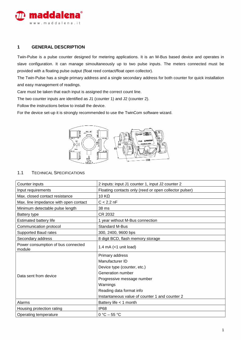
Care must be taken that each input is assigned the correct count line.
The two counter inputs are identified as J1 (counter 1) and J2 (counter 2).
Follow the instructions below to install the device.
For the device set-up it is strongly recommended to use the TwinCom software wizard.
1.1 TECHNICAL SPECIFICATIONS
Counter inputs 2 inputs: input J1 counter 1, input J2 counter 2
Input requirements Floating contacts only (reed or open collector pulser)
Max. closed contact resistance 10 KΩ
Max. line impedance with open contact C < 2.2 nF
Minimum detectable pulse length 38 ms
Battery type CR 2032
Estimated battery life 1 year without M-Bus connection
Communication protocol Standard M-Bus
Supported Baud rates 300, 2400, 9600 bps
Secondary address 8 digit BCD, flash memory storage
Power consumption of bus connected module
1.4 mA (<1 unit load)
Data sent from device
Primary address
Manufacturer ID
Device type (counter, etc.)
Generation number
Progressive message number
Warnings
Reading data format info
Instantaneous value of counter 1 and counter 2
Alarms Battery life < 1 month
Housing protection rating IP68
Operating temperature 0 °C – 55 °C
2
Storage temperature -20 °C – 70 °C
Humidity (noncondensing) 10% – 70%
1.2 DEFAULT PARAMETERS
When the device is activated for the first time the following default parameters are available.
Primary address 0
Serial port setting 8 bit even parity 2400 bps
Counters set-up (both counters) Medium water, 10 liter/pulse, counter = 0, multiplier 1/1
1.3 TWIN-PULSE INSTALLATION PROCEDURE
The installation procedure consists of three steps:
1) module activation
2) wire connections
3) parameter configuration
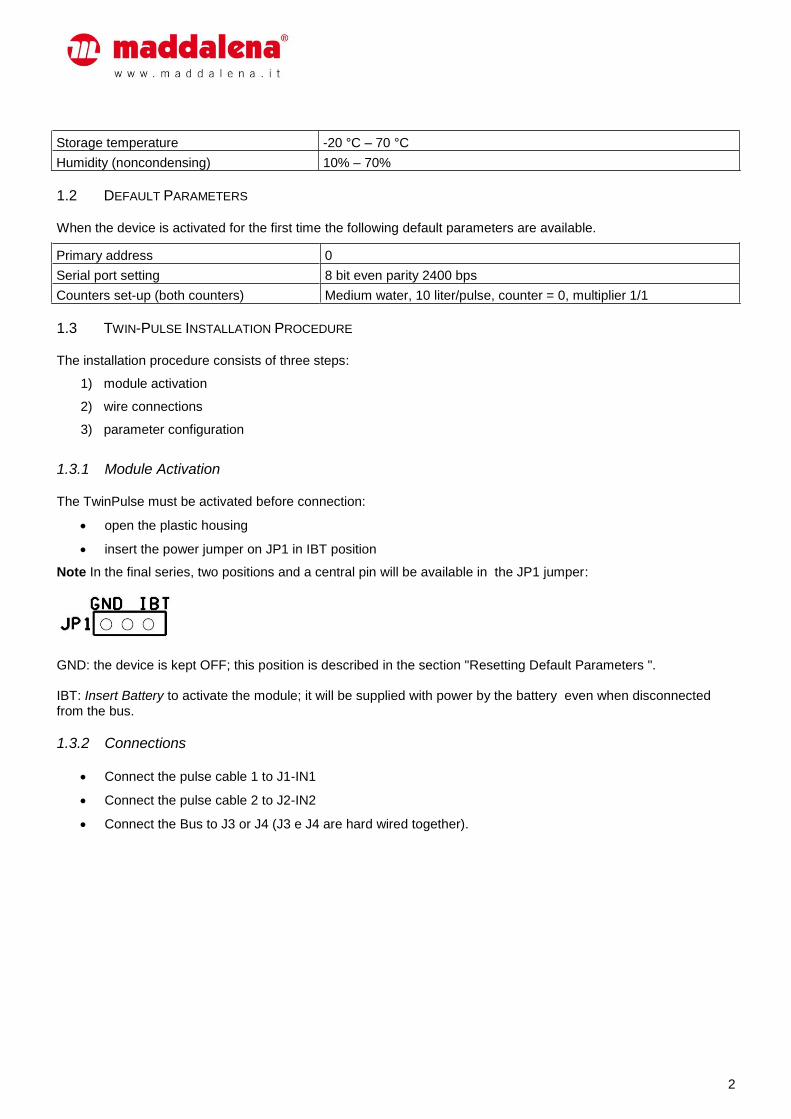
1.3.1 Module Activation
The TwinPulse must be activated before connection:
open the plastic housing
insert the power jumper on JP1 in IBT position
Note In the final series, two positions and a central pin will be available in the JP1 jumper:
GND: the device is kept OFF; this position is described in the section "Resetting Default Parameters ". IBT: Insert Battery to activate the module; it will be supplied with power by the battery even when disconnected from the bus.
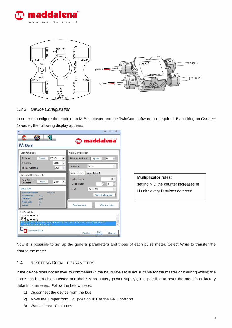
1.3.2 Connections
Connect the pulse cable 1 to J1-IN1
Connect the pulse cable 2 to J2-IN2
Connect the Bus to J3 or J4 (J3 e J4 are hard wired together).
3
1.3.3 Device Configuration
In order to configure the module an M-Bus master and the TwinCom software are required. By clicking on Connect
to meter, the following display appears:
Now it is possibile to set up the general parameters and those of each pulse meter. Select Write to transfer the
data to the meter.
1.4 RESETTING DEFAULT PARAMETERS
If the device does not answer to commands (if the baud rate set is not suitable for the master or if during writing the
cable has been disconnected and there is no battery power supply), it is possible to reset the meter’s at factory
default parameters. Follow the below steps:
1) Disconnect the device from the bus
2) Move the jumper from JP1 position IBT to the GND position
3) Wait at least 10 minutes
Multiplicator rules:
setting N/D the counter increases of
N units every D pulses detected
4
4) Re-position JP1 on IBT
5) Reconnect the device to the bus
To speed up the resume of device do the following:
1) Disconnect the device from the bus
2) Remove the jumper JP1
3) Short-circuit pins 1 and 2 of connector J5 with a wire or tweezers
4) Insert JP1
5) Reconnect the device to the bus.
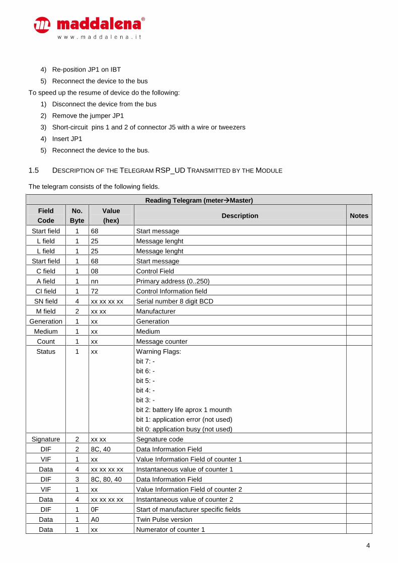
1.5 DESCRIPTION OF THE TELEGRAM RSP_UD TRANSMITTED BY THE MODULE
The telegram consists of the following fields.
Reading Telegram (meterMaster)
Field
Code
No.
Byte
Value
(hex) Description Notes
Start field 1 68 Start message
L field 1 25 Message lenght
L field 1 25 Message lenght
Start field 1 68 Start message
C field 1 08 Control Field
A field 1 nn Primary address (0..250)
CI field 1 72 Control Information field
SN field 4 xx xx xx xx Serial number 8 digit BCD
M field 2 xx xx Manufacturer
Generation 1 xx Generation
Medium 1 xx Medium
Count 1 xx Message counter
Status 1 xx Warning Flags:
bit 7: -
bit 6: -
bit 5: -
bit 4: -
bit 3: -
bit 2: battery life aprox 1 mounth
bit 1: application error (not used)
bit 0: application busy (not used)
Signature 2 xx xx Segnature code
DIF 2 8C, 40 Data Information Field
VIF 1 xx Value Information Field of counter 1
Data 4 xx xx xx xx Instantaneous value of counter 1
DIF 3 8C, 80, 40 Data Information Field
VIF 1 xx Value Information Field of counter 2
Data 4 xx xx xx xx Instantaneous value of counter 2
DIF 1 0F Start of manufacturer specific fields
Data 1 A0 Twin Pulse version
Data 1 xx Numerator of counter 1

5
Reading Telegram (meterMaster)
Field
Code
No.
Byte
Value
(hex) Description Notes
Data 1 xx Denominator of counter 1
Data 1 xx Numerator of counter 2
Data 1 xx Denominator of counter 2
Data 1 xx Free for service
CS 1 xx Check sum
End Field 1 16 End of message
6
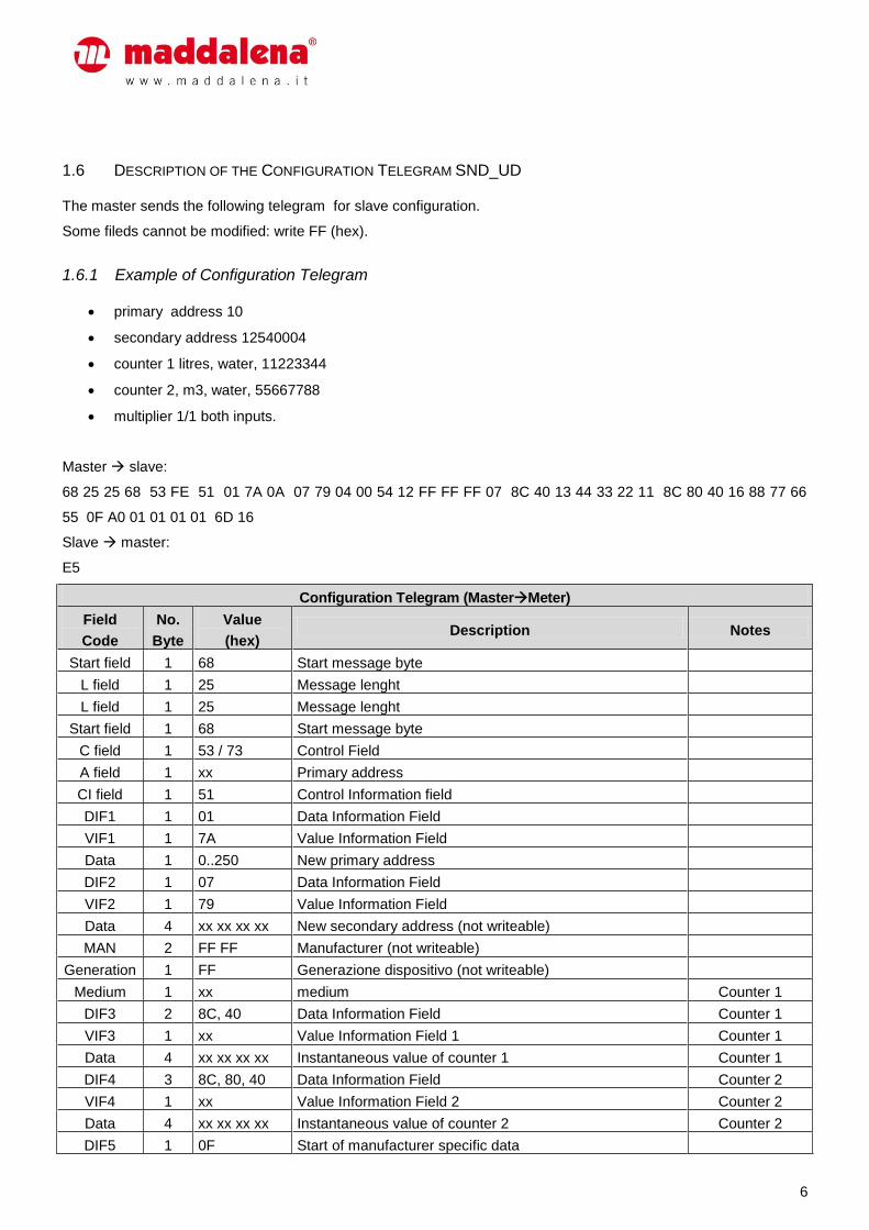
1.6 DESCRIPTION OF THE CONFIGURATION TELEGRAM SND_UD
The master sends the following telegram for slave configuration.
Some fileds cannot be modified: write FF (hex).
1.6.1 Example of Configuration Telegram
primary address 10
secondary address 12540004
counter 1 litres, water, 11223344
counter 2, m3, water, 55667788
multiplier 1/1 both inputs.
Master slave:
68 25 25 68 53 FE 51 01 7A 0A 07 79 04 00 54 12 FF FF FF 07 8C 40 13 44 33 22 11 8C 80 40 16 88 77 66
55 0F A0 01 01 01 01 6D 16
Slave master:
E5
Configuration Telegram (MasterMeter)
Field
Code
No.
Byte
Value
(hex) Description Notes
Start field 1 68 Start message byte
L field 1 25 Message lenght
L field 1 25 Message lenght
Start field 1 68 Start message byte
C field 1 53 / 73 Control Field
A field 1 xx Primary address
CI field 1 51 Control Information field
DIF1 1 01 Data Information Field
VIF1 1 7A Value Information Field
Data 1 0..250 New primary address
DIF2 1 07 Data Information Field
VIF2 1 79 Value Information Field
Data 4 xx xx xx xx New secondary address (not writeable)
MAN 2 FF FF Manufacturer (not writeable)
Generation 1 FF Generazione dispositivo (not writeable)
Medium 1 xx medium Counter 1
DIF3 2 8C, 40 Data Information Field Counter 1
VIF3 1 xx Value Information Field 1 Counter 1
Data 4 xx xx xx xx Instantaneous value of counter 1 Counter 1
DIF4 3 8C, 80, 40 Data Information Field Counter 2
VIF4 1 xx Value Information Field 2 Counter 2
Data 4 xx xx xx xx Instantaneous value of counter 2 Counter 2
DIF5 1 0F Start of manufacturer specific data
7
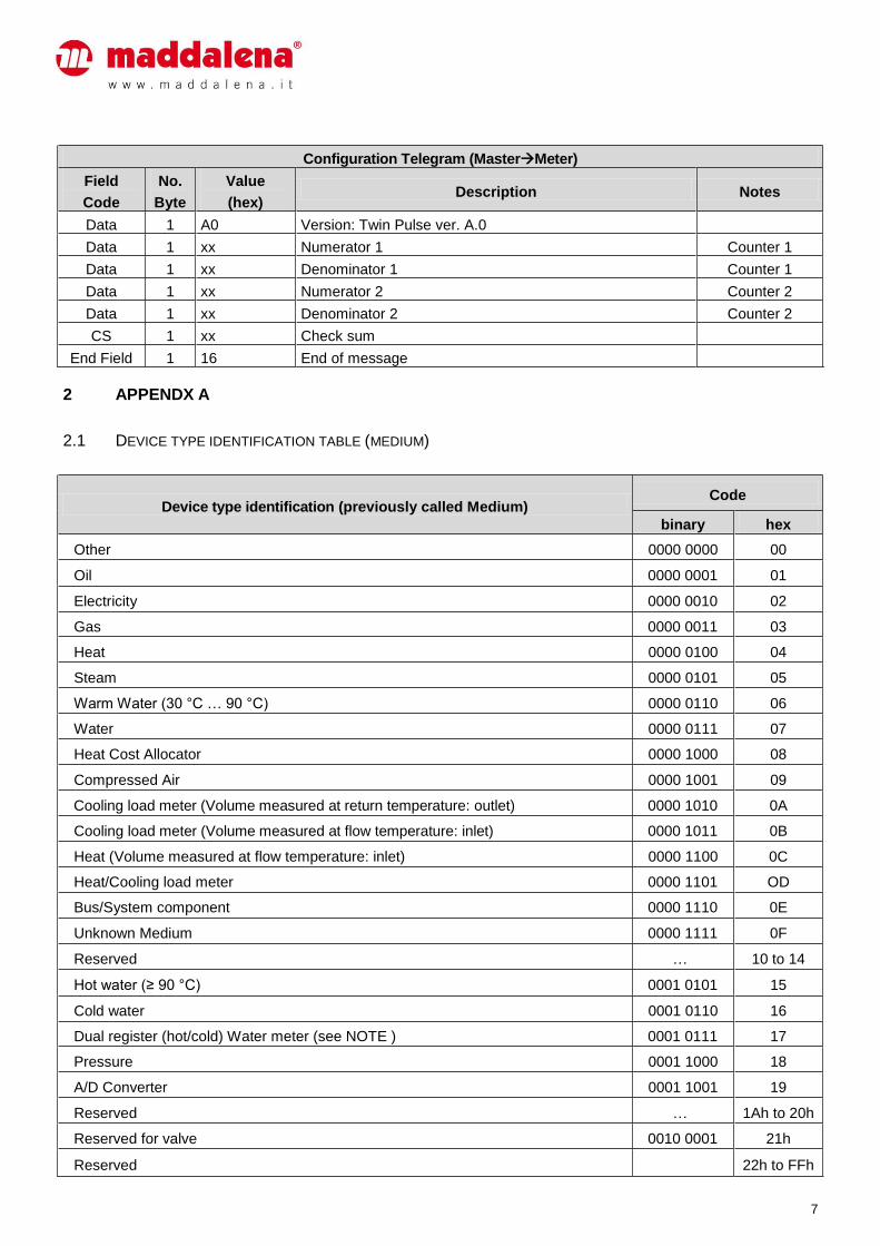
Configuration Telegram (MasterMeter)
Field
Code
No.
Byte
Value
(hex) Description Notes
Data 1 A0 Version: Twin Pulse ver. A.0
Data 1 xx Numerator 1 Counter 1
Data 1 xx Denominator 1 Counter 1
Data 1 xx Numerator 2 Counter 2
Data 1 xx Denominator 2 Counter 2
CS 1 xx Check sum
End Field 1 16 End of message
2 APPENDX A
2.1 DEVICE TYPE IDENTIFICATION TABLE (MEDIUM)
Device type identification (previously called Medium) Code
binary hex
Other 0000 0000 00
Oil 0000 0001 01
Electricity 0000 0010 02
Gas 0000 0011 03
Heat 0000 0100 04
Steam 0000 0101 05
Warm Water (30 °C … 90 °C) 0000 0110 06
Water 0000 0111 07
Heat Cost Allocator 0000 1000 08
Compressed Air 0000 1001 09
Cooling load meter (Volume measured at return temperature: outlet) 0000 1010 0A
Cooling load meter (Volume measured at flow temperature: inlet) 0000 1011 0B
Heat (Volume measured at flow temperature: inlet) 0000 1100 0C
Heat/Cooling load meter 0000 1101 OD
Bus/System component 0000 1110 0E
Unknown Medium 0000 1111 0F
Reserved … 10 to 14
Hot water (≥ 90 °C) 0001 0101 15
Cold water 0001 0110 16
Dual register (hot/cold) Water meter (see NOTE ) 0001 0111 17
Pressure 0001 1000 18
A/D Converter 0001 1001 19
Reserved … 1Ah to 20h
Reserved for valve 0010 0001 21h
Reserved 22h to FFh
8
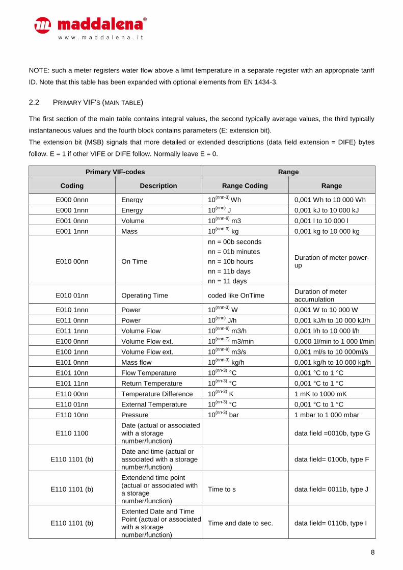
NOTE: such a meter registers water flow above a limit temperature in a separate register with an appropriate tariff
ID. Note that this table has been expanded with optional elements from EN 1434-3.
2.2 PRIMARY VIF'S (MAIN TABLE)
The first section of the main table contains integral values, the second typically average values, the third typically
instantaneous values and the fourth block contains parameters (E: extension bit).
The extension bit (MSB) signals that more detailed or extended descriptions (data field extension = DIFE) bytes
follow. E = 1 if other VIFE or DIFE follow. Normally leave E = 0.
Primary VIF-codes Range
Coding Description Range Coding Range
E000 0nnn Energy 10(nnn-3)
Wh 0,001 Wh to 10 000 Wh
E000 1nnn Energy 10(nnn)
J 0,001 kJ to 10 000 kJ
E001 0nnn Volume 10(nnn-6)
m3 0,001 l to 10 000 l
E001 1nnn Mass 10(nnn-3)
kg 0,001 kg to 10 000 kg
E010 00nn On Time
nn = 00b seconds
nn = 01b minutes
nn = 10b hours
nn = 11b days
nn = 11 days
Duration of meter power-up
E010 01nn Operating Time coded like OnTime Duration of meter accumulation
E010 1nnn Power 10(nnn-3)
W 0,001 W to 10 000 W
E011 0nnn Power 10(nnn)
J/h 0,001 kJ/h to 10 000 kJ/h
E011 1nnn Volume Flow 10(nnn-6)
m3/h 0,001 l/h to 10 000 l/h
E100 0nnn Volume Flow ext. 10(nnn-7)
m3/min 0,000 1l/min to 1 000 l/min
E100 1nnn Volume Flow ext. 10(nnn-9)
m3/s 0,001 ml/s to 10 000ml/s
E101 0nnn Mass flow 10(nnn-3)
kg/h 0,001 kg/h to 10 000 kg/h
E101 10nn Flow Temperature 10(nn-3)
°C 0,001 °C to 1 °C
E101 11nn Return Temperature 10(nn-3)
°C 0,001 °C to 1 °C
E110 00nn Temperature Difference 10(nn-3)
K 1 mK to 1000 mK
E110 01nn External Temperature 10(nn-3)
°C 0,001 °C to 1 °C
E110 10nn Pressure 10(nn-3)
bar 1 mbar to 1 000 mbar
E110 1100 Date (actual or associated with a storage number/function)
data field =0010b, type G
E110 1101 (b) Date and time (actual or associated with a storage number/function)
data field= 0100b, type F
E110 1101 (b)
Extendend time point (actual or associated with a storage number/function)
Time to s data field= 0011b, type J
E110 1101 (b)
Extented Date and Time Point (actual or associated with a storage number/function)
Time and date to sec. data field= 0110b, type I
9
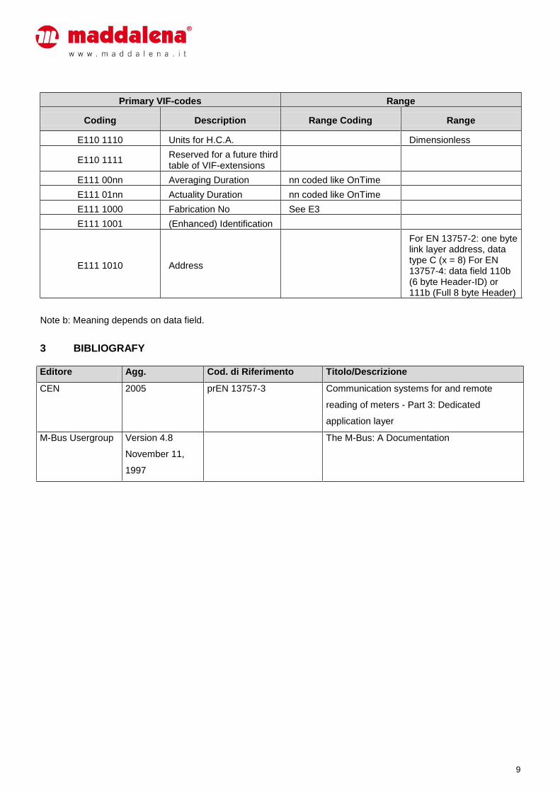
Primary VIF-codes Range
Coding Description Range Coding Range
E110 1110 Units for H.C.A. Dimensionless
E110 1111 Reserved for a future third table of VIF-extensions
E111 00nn Averaging Duration nn coded like OnTime
E111 01nn Actuality Duration nn coded like OnTime
E111 1000 Fabrication No See E3
E111 1001 (Enhanced) Identification
E111 1010 Address
For EN 13757-2: one byte link layer address, data type C (x = 8) For EN 13757-4: data field 110b (6 byte Header-ID) or 111b (Full 8 byte Header)
Note b: Meaning depends on data field.
3 BIBLIOGRAFY
Editore Agg. Cod. di Riferimento Titolo/Descrizione
CEN 2005 prEN 13757-3 Communication systems for and remote
reading of meters - Part 3: Dedicated
application layer
M-Bus Usergroup Version 4.8
November 11,
1997
The M-Bus: A Documentation


