Operating instructions Wire feed units for automated applications GB M drive 4 Rob 3 LI M drive 4 Rob 3 RE 099-005110-EW501 Observe additional system documents! 06.02.2013 Register now! For your benefit Jetzt Registrieren und Profitieren! www.ewm-group.com *Details for ewm-warranty www.ewm-group.com *
Transcript
Operating instructions
Wire feed units for automated applications
GB
M drive 4 Rob 3 LI M drive 4 Rob 3 RE
099-005110-EW501 Observe additional system documents! 06.02.2013
Register now!For your benefitJetzt Registrierenund Profitieren!
www.ewm-group.com
*Det
ails
for e
wm
-war
rant
yw
ww
.ew
m-g
roup
.com
*
General instructions
CAUTION
Read the operating instructions! The operating instructions provide an introduction to the safe use of the products. • Read the operating instructions for all system components! • Observe accident prevention regulations! • Observe all local regulations! • Confirm with a signature where appropriate.
NOTE
In the event of queries on installation, commissioning, operation or special conditions at the installation site, or on usage, please contact your sales partner or our customer service department on +49 2680 181-0. A list of authorised sales partners can be found at www.ewm-group.com.
Liability relating to the operation of this equipment is restricted solely to the function of the equipment. No other form of liability, regardless of type, shall be accepted. This exclusion of liability shall be deemed accepted by the user on commissioning the equipment. The manufacturer is unable to monitor whether or not these instructions or the conditions and methods are observed during installation, operation, usage and maintenance of the equipment. An incorrectly performed installation can result in material damage and injure persons as a result. For this reason, we do not accept any responsibility or liability for losses, damages or costs arising from incorrect installation, improper operation or incorrect usage and maintenance or any actions connected to this in any way.
2.1 Notes on the use of these operating instructions ..........................................................................6 2.2 Explanation of icons.......................................................................................................................7 2.3 General ..........................................................................................................................................8 2.4 Transport and installation ............................................................................................................12 2.5 Ambient conditions.......................................................................................................................13
2.5.1 In operation...................................................................................................................13 2.5.2 Transport and storage ..................................................................................................13
3 Intended use .........................................................................................................................................14 3.1 Applications..................................................................................................................................14
3.1.1 Automation ...................................................................................................................14 3.1.2 For operation only with the following equipment ..........................................................14
3.2 Documents which also apply .......................................................................................................15 3.2.1 Warranty .......................................................................................................................15 3.2.2 Declaration of Conformity.............................................................................................15 3.2.3 Welding in environments with increased electrical hazards.........................................15 3.2.4 Service documents (spare parts and circuit diagrams) ................................................15 3.2.5 Calibration/Validation ...................................................................................................15
4 Machine description – quick overview ..............................................................................................16 4.1 M drive 4 Rob 3 LI........................................................................................................................16
4.1.1 Front view .....................................................................................................................16 4.1.2 Rear view......................................................................................................................17
4.2 M drive 4 Rob 3 RE......................................................................................................................18 4.2.1 Front view .....................................................................................................................18 4.2.2 Rear view......................................................................................................................19
4.3 Machine control – Operating elements........................................................................................20 5 Design and function.............................................................................................................................21
5.1 General ........................................................................................................................................21 5.2 Installation....................................................................................................................................22
5.2.1 Mounting without carrier plate ......................................................................................23 5.2.2 Mounting with carrier plate (option) ..............................................................................23 5.2.3 Strain relief option for third party intermediate hose package......................................24
5.3 Intermediate hose package connection.......................................................................................26 5.3.1 M drive 4 Rob 3 LI ........................................................................................................26 5.3.2 M drive 4 Rob 3 RE ......................................................................................................27
5.4 Welding torch connection ............................................................................................................28 5.4.1 M drive 4 Rob 3 LI ........................................................................................................28 5.4.2 M drive 4 Rob 3 RE ......................................................................................................29
5.5 Wire feed......................................................................................................................................30 5.5.1 Changing the wire feed rollers......................................................................................30 5.5.2 Inching the wire electrode ............................................................................................31
6.2.3 Annual test (inspection and testing during operation) ..................................................36 6.3 Maintenance work ........................................................................................................................36 6.4 Disposing of equipment................................................................................................................37
6.4.1 Manufacturer's declaration to the end user ..................................................................37 6.5 Meeting the requirements of RoHS..............................................................................................37
7 Technical data.......................................................................................................................................38 7.1 M drive 4 Rob 3............................................................................................................................38
7.1.1 Dimensions ...................................................................................................................38 7.1.1.1 M drive 4 Rob 3 LI .........................................................................................38
7.1.2 Dimensions ...................................................................................................................38 7.1.2.1 M drive 4 Rob 3 RE.......................................................................................38
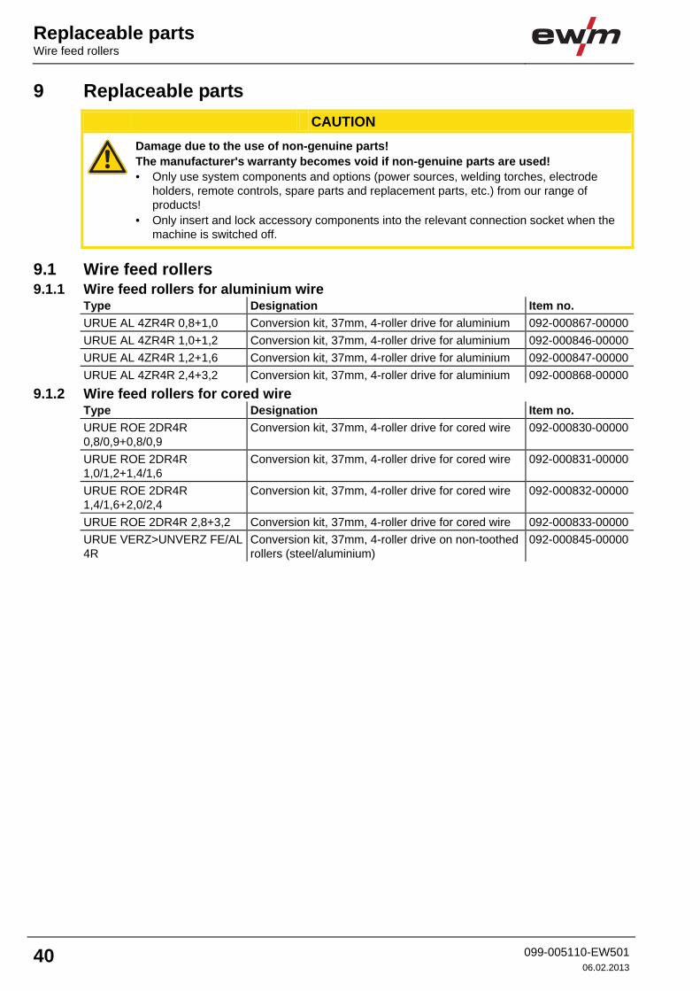
9.1.1 Wire feed rollers for aluminium wire .............................................................................40 9.1.2 Wire feed rollers for cored wire.....................................................................................40
10 Circuit diagrams ...................................................................................................................................41 10.1 M drive 4 Rob 3 LI / RE................................................................................................................41
11 Appendix A............................................................................................................................................42 11.1 Overview of EWM branches.........................................................................................................42
Contents
Notes on the use of these operating instructions
099-005110-EW501 06.02.2013
5
Safety instructions Notes on the use of these operating instructions
6 099-005110-EW50106.02.2013
2 Safety instructions 2.1 Notes on the use of these operating instructions
DANGER
Working or operating procedures which must be closely observed to prevent imminent serious and even fatal injuries. • Safety notes include the "DANGER" keyword in the heading with a general warning symbol. • The hazard is also highlighted using a symbol on the edge of the page.
WARNING
Working or operating procedures which must be closely observed to prevent serious and even fatal injuries. • Safety notes include the "WARNING" keyword in the heading with a general warning
symbol. • The hazard is also highlighted using a symbol in the page margin.
CAUTION
Working or operating procedures which must be closely observed to prevent possible minor personal injury. • The safety information includes the "CAUTION" keyword in its heading with a general
warning symbol. • The risk is explained using a symbol on the edge of the page.
CAUTION
Working and operating procedures which must be followed precisely to avoid damaging or destroying the product. • The safety information includes the "CAUTION" keyword in its heading without a general
warning symbol. • The hazard is explained using a symbol at the edge of the page.
NOTE
Special technical points which users must observe. • Notes include the "NOTE" keyword in the heading without a general warning symbol.
Instructions and lists detailing step-by-step actions for given situations can be recognised via bullet points, e.g.: • Insert the welding current lead socket into the relevant socket and lock.
Safety instructions
Explanation of icons
099-005110-EW501 06.02.2013
7
2.2 Explanation of icons
Symbol Description
Press
Do not press
Turn
Switch
l
0
Switch off machine
l
0
Switch on machine
ENTER (enter the menu)
NAVIGATION (Navigating in the menu)
EXIT (Exit the menu)
Time display (example: wait 4s/press)
Interruption in the menu display (other setting options possible)
Tool not required/do not use
Tool required/use
Safety instructions General
8 099-005110-EW50106.02.2013
2.3 General
DANGER
Electromagnetic fields! The power source may cause electrical or electromagnetic fields to be produced which could affect the correct functioning of electronic equipment such as IT or CNC devices, telecommunication lines, power cables, signal lines and pacemakers. • Observe the maintenance instructions! (see Maintenance and Testing chapter) • Unwind welding leads completely! • Shield devices or equipment sensitive to radiation accordingly! • The correct functioning of pacemakers may be affected (obtain advice from a doctor if
necessary).
Do not carry out any unauthorised repairs or modifications! To avoid injury and equipment damage, the unit must only be repaired or modified by specialist, skilled persons! The warranty becomes null and void in the event of unauthorised interference. • Appoint only skilled persons for repair work (trained service personnel)!
Electric shock! Welding machines use high voltages which can result in potentially fatal electric shocks and burns on contact. Even low voltages can cause you to get a shock and lead to accidents. • Do not touch any live parts in or on the machine! • Connection cables and leads must be free of faults! • Switching off alone is not sufficient! • Place welding torch and stick electrode holder on an insulated surface! • The unit should only be opened by specialist staff after the mains plug has been unplugged!• Only wear dry protective clothing! • Wait for 4 minutes until the capacitors have discharged!
WARNING
Validity of this document! This document is only valid in combination with the operating instructions for the power source being used (welding machine)! • Read the operating instructions, in particular the safety instructions for the power source
(welding machine)!
Risk of accidents if these safety instructions are not observed! Non-observance of these safety instructions is potentially fatal! • Carefully read the safety information in this manual! • Observe the accident prevention regulations in your country. • Inform persons in the working area that they must observe the regulations!
Explosion risk! Apparently harmless substances in closed containers may generate excessive pressure when heated. • Move containers with inflammable or explosive liquids away from the working area! • Never heat explosive liquids, dusts or gases by welding or cutting!
Safety instructions
General
099-005110-EW501 06.02.2013
9
WARNING
Risk of injury due to radiation or heat! Arc radiation results in injury to skin and eyes. Contact with hot workpieces and sparks results in burns. • Use welding shield or welding helmet with the appropriate safety level (depending on the
application)! • Wear dry protective clothing (e.g. welding shield, gloves, etc.) according to the relevant
regulations in the country in question! • Protect persons not involved in the work against arc beams and the risk of glare using
safety curtains!
Smoke and gases! Smoke and gases can lead to breathing difficulties and poisoning. In addition, solvent vapour (chlorinated hydrocarbon) may be converted into poisonous phosgene due to the ultraviolet radiation of the arc! • Ensure that there is sufficient fresh air! • Keep solvent vapour away from the arc beam field! • Wear suitable breathing apparatus if appropriate!
Fire hazard! Flames may arise as a result of the high temperatures, stray sparks, glowing-hot parts and hot slag produced during the welding process. Stray welding currents can also result in flames forming! • Check for fire hazards in the working area! • Do not carry any easily flammable objects such as matches or lighters. • Keep appropriate fire extinguishing equipment to hand in the working area! • Thoroughly remove any residue of flammable substances from the workpiece before
starting welding. • Only continue work on welded workpieces once they have cooled down.
Do not allow to come into contact with flammable material! • Connect welding leads correctly!
Danger when coupling multiple power sources! Coupling multiple power sources in parallel or in series has to be carried out by qualified personnel and in accordance with the manufacturer's guidelines. Before bringing the power sources into service for arc welding operations, a test has to verify that they cannot exceed the maximum allowed open circuit voltage. • Connection of the machine may be carried out by qualified personnel only! • When decommissioning individual power sources, all mains and welding current leads have
to be safely disconnected from the welding system as a whole. (danger due to inverse voltages)!
CAUTION
Noise exposure! Noise exceeding 70 dBA can cause permanent hearing damage! • Wear suitable ear protection! • Persons located within the working area must wear suitable ear protection!
Safety instructions General
10 099-005110-EW50106.02.2013
CAUTION
Obligations of the operator! The respective national directives and laws must be observed for operation of the machine! • National implementation of the framework directive (89/391/EWG), as well as the
associated individual directives. • In particular, directive (89/655/EWG), on the minimum regulations for safety and health
protection when staff members use equipment during work. • The regulations regarding work safety and accident prevention for the respective country. • Setting up and operating the machine according to IEC 60974-9. • Check at regular intervals that users are working in a safety-conscious way. • Regular checks of the machine according to IEC 60974-4.
Damage due to the use of non-genuine parts! The manufacturer's warranty becomes void if non-genuine parts are used! • Only use system components and options (power sources, welding torches, electrode
holders, remote controls, spare parts and replacement parts, etc.) from our range of products!
• Only insert and lock accessory components into the relevant connection socket when the machine is switched off.
Damage to the machine due to stray welding currents! Stray welding currents can destroy protective earth conductors, damage equipment and electronic devices and cause overheating of components leading to fire. • Make sure all welding leads are securely connected and check regularly. • Always ensure a proper and secure electrical connection to the workpiece! • Set up, attach or suspend all conductive power source components like casing, transport
vehicle and crane frames so they are insulated! • Do not place any other electronic devices such as drillers or angle grinders, etc., on the
power source, transport vehicle or crane frames unless they are insulated! • Always put welding torches and electrode holders on an insulated surface when they are
not in use!
Mains connection Requirements for connection to the public mains network High-performance machines can influence the mains quality by taking current from the mains network. For some types of machines, connection restrictions or requirements relating to the maximum possible line impedance or the necessary minimum supply capacity at the interface with the public network (Point of Common Coupling, PCC) can therefore apply. In this respect, attention is also drawn to the machines' technical data. In this case, it is the responsibility of the operator, where necessary in consultation with the mains network operator, to ensure that the machine can be connected.
Safety instructions
General
099-005110-EW501 06.02.2013
11
CAUTION
EMC Machine Classification In accordance with IEC 60974-10, welding machines are grouped in two electromagnetic compatibility classes (see technical data): Class A machines are not intended for use in residential areas where the power supply comes from the low-voltage public mains network. When ensuring the electromagnetic compatibility of class A machines, difficulties can arise in these areas due to interference not only in the supply lines but also in the form of radiated interference. Class B machines fulfil the EMC requirements in industrial as well as residential areas, including residential areas connected to the low-voltage public mains network. Setting up and operating When operating arc welding systems, in some cases, electro-magnetic interference can occur although all of the welding machines comply with the emission limits specified in the standard. The user is responsible for any interference caused by welding. In order to evaluate any possible problems with electromagnetic compatibility in the surrounding area, the user must consider the following: (see also EN 60974-10 Appendix A) • Mains, control, signal and telecommunication lines • Radios and televisions • Computers and other control systems • Safety equipment • The health of neighbouring persons, especially if they have a pacemaker or wear a hearing
aid • Calibration and measuring equipment • The immunity to interference of other equipment in the surrounding area • The time of day at which the welding work must be carried out Recommendations for reducing interference emission • Mains connection, e.g. additional mains filter or shielding with a metal tube • Maintenance of the arc welding equipment • Welding leads should be as short as possible and run closely together along the ground • Potential equalization • Earthing of the workpiece. In cases where it is not possible to earth the workpiece directly,
it should be connected by means of suitable capacitors. • Shielding from other equipment in the surrounding area or the entire welding system
Safety instructions Transport and installation
12 099-005110-EW50106.02.2013
2.4 Transport and installation
WARNING
Incorrect handling of shielding gas cylinders! Incorrect handling of shielding gas cylinders can result in serious and even fatal injury. • Observe the instructions from the gas manufacturer and in any relevant regulations
concerning the use of compressed air! • Place shielding gas cylinders in the holders provided for them and secure with fixing
devices. • Avoid heating the shielding gas cylinder!
Risk of accident due to improper transport of machines that may not be lifted! Do not lift or suspend the machine! The machine can fall down and cause injuries! The handles and brackets are suitable for transport by hand only! • The machine may not be lifted by crane or suspended!
CAUTION
Risk of tipping! There is a risk of the machine tipping over and injuring persons or being damaged itself during movement and set up. Tilt resistance is guaranteed up to an angle of 10° (according to IEC 60974-1). • Set up and transport the machine on level, solid ground. • Secure add-on parts using suitable equipment.
Damage due to supply lines not being disconnected! During transport, supply lines which have not been disconnected (mains supply leads, control leads, etc.) may cause hazards such as connected equipment tipping over and injuring persons! • Disconnect supply lines!
CAUTION
Equipment damage when not operated in an upright position! The units are designed for operation in an upright position! Operation in non-permissible positions can cause equipment damage. • Only transport and operate in an upright position!
Safety instructions
Ambient conditions
099-005110-EW501 06.02.2013
13
2.5 Ambient conditions
CAUTION
Installation site! The machine must not be operated in the open air and must only be set up and operated on a suitable, stable and level base! • The operator must ensure that the ground is non-slip and level, and provide sufficient
lighting for the place of work. • Safe operation of the machine must be guaranteed at all times.
CAUTION
Equipment damage due to dirt accumulation! Unusually high quantities of dust, acid, corrosive gases or substances may damage the equipment. • Avoid high volumes of smoke, vapour, oil vapour and grinding dust! • Avoid ambient air containing salt (sea air)!
Non-permissible ambient conditions! Insufficient ventilation results in a reduction in performance and equipment damage. • Observe the ambient conditions! • Keep the cooling air inlet and outlet clear! • Observe the minimum distance of 0.5 m from obstacles!
2.5.1 In operation Temperature range of the ambient air: • -20 °C to +40 °C Relative air humidity: • Up to 50% at 40 °C • Up to 90% at 20 °C
2.5.2 Transport and storage Storage in an enclosed space, temperature range of the ambient air: • -25 °C to +55 °C Relative air humidity • Up to 90% at 20 °C
Intended use Applications
14 099-005110-EW50106.02.2013
3 Intended use This machine has been manufactured according to the latest developments in technology and current regulations and standards. It must only be operated in line with the instructions on correct usage.
WARNING
Hazards due to improper usage! Hazards may arise for persons, animals and material objects if the equipment is not used correctly. No liability is accepted for any damages arising from improper usage! • The equipment must only be used in line with proper usage and by trained or expert staff! • Do not modify or convert the equipment improperly!
CAUTION
Damage due to the use of non-genuine parts! The manufacturer's warranty becomes void if non-genuine parts are used! • Only use system components and options (power sources, welding torches, electrode
holders, remote controls, spare parts and replacement parts, etc.) from our range of products!
• Only insert and lock accessory components into the relevant connection socket when the machine is switched off.
3.1 Applications 3.1.1 Automation
Automated, robot-controlled welding production with the digital robot power sources. • Phoenix • alpha Q
3.1.2 For operation only with the following equipment Welding machine • Phoenix 352, 452, 552 puls • Phoenix 352, 452, 552, 1002 RC puls • Phoenix 552 RC puls Tandem • alpha Q 352, 552 RC • alpha Q 352, 552
Intended use
Documents which also apply
099-005110-EW501 06.02.2013
15
3.2 Documents which also apply 3.2.1 Warranty
NOTE
For further information, please see the accompanying supplementary sheets "Machine and Company Data, Maintenance and Testing, Warranty"!
3.2.2 Declaration of Conformity
The designated machine conforms to EC Directives and standards in terms of its design and construction: • EC Low Voltage Directive (2006/95/EC), • EC EMC Directive (2004/108/EC),
This declaration shall become null and void in the event of unauthorised modifications, improperly conducted repairs, non-observance of the deadlines for the repetition test and / or non-permitted conversion work not specifically authorised by the manufacturer. The original copy of the declaration of conformity is enclosed with the unit.
3.2.3 Welding in environments with increased electrical hazards
In compliance with IEC / DIN EN 60974, VDE 0544 the machines can be used in environments with an increased electrical hazard.
3.2.4 Service documents (spare parts and circuit diagrams)
DANGER
Do not carry out any unauthorised repairs or modifications! To avoid injury and equipment damage, the unit must only be repaired or modified by specialist, skilled persons! The warranty becomes null and void in the event of unauthorised interference. • Appoint only skilled persons for repair work (trained service personnel)!
Original copies of the circuit diagrams are enclosed with the unit. Spare parts can be obtained from the relevant authorised dealer.
3.2.5 Calibration/Validation We hereby confirm that this machine has been tested using calibrated measuring equipment, as stipulated in IEC/EN 60974, ISO/EN 17662, EN 50504, and complies with the admissible tolerances. Recommended calibration interval: 12 months
Machine description – quick overview M drive 4 Rob 3 LI
16 099-005110-EW50106.02.2013
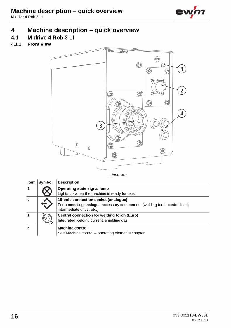
4 Machine description – quick overview 4.1 M drive 4 Rob 3 LI 4.1.1 Front view
4
3
2
1
Figure 4-1
Item Symbol Description 0 1
Operating state signal lamp Lights up when the machine is ready for use.
2
19-pole connection socket (analogue) For connecting analogue accessory components (welding torch control lead, intermediate drive, etc.)
3
Central connection for welding torch (Euro) Integrated welding current, shielding gas
4 Machine control See Machine control – operating elements chapter
Machine description – quick overview
M drive 4 Rob 3 LI
099-005110-EW501 06.02.2013
17
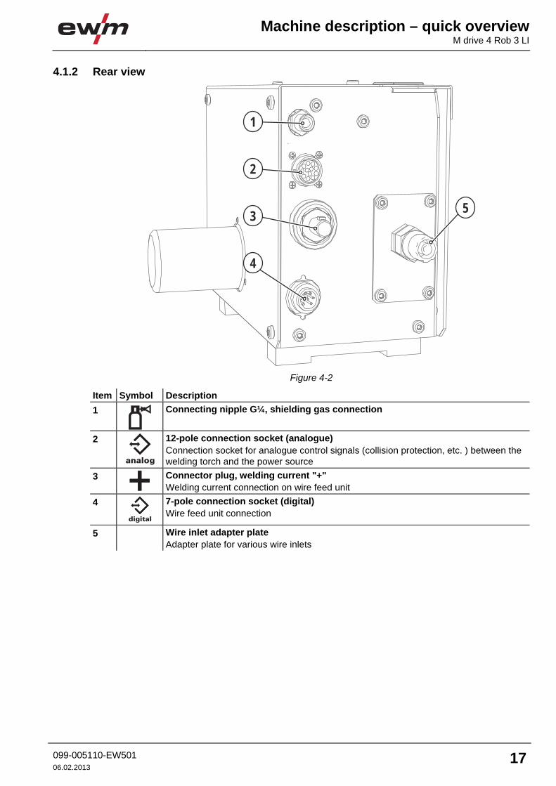
4.1.2 Rear view
4
53
2
1
Figure 4-2
Item Symbol Description 0 1
Connecting nipple G¼, shielding gas connection
2
analog
12-pole connection socket (analogue) Connection socket for analogue control signals (collision protection, etc. ) between the welding torch and the power source
3
Connector plug, welding current "+" Welding current connection on wire feed unit
4 digital
7-pole connection socket (digital) Wire feed unit connection
5 Wire inlet adapter plate Adapter plate for various wire inlets
Machine description – quick overview M drive 4 Rob 3 RE
18 099-005110-EW50106.02.2013
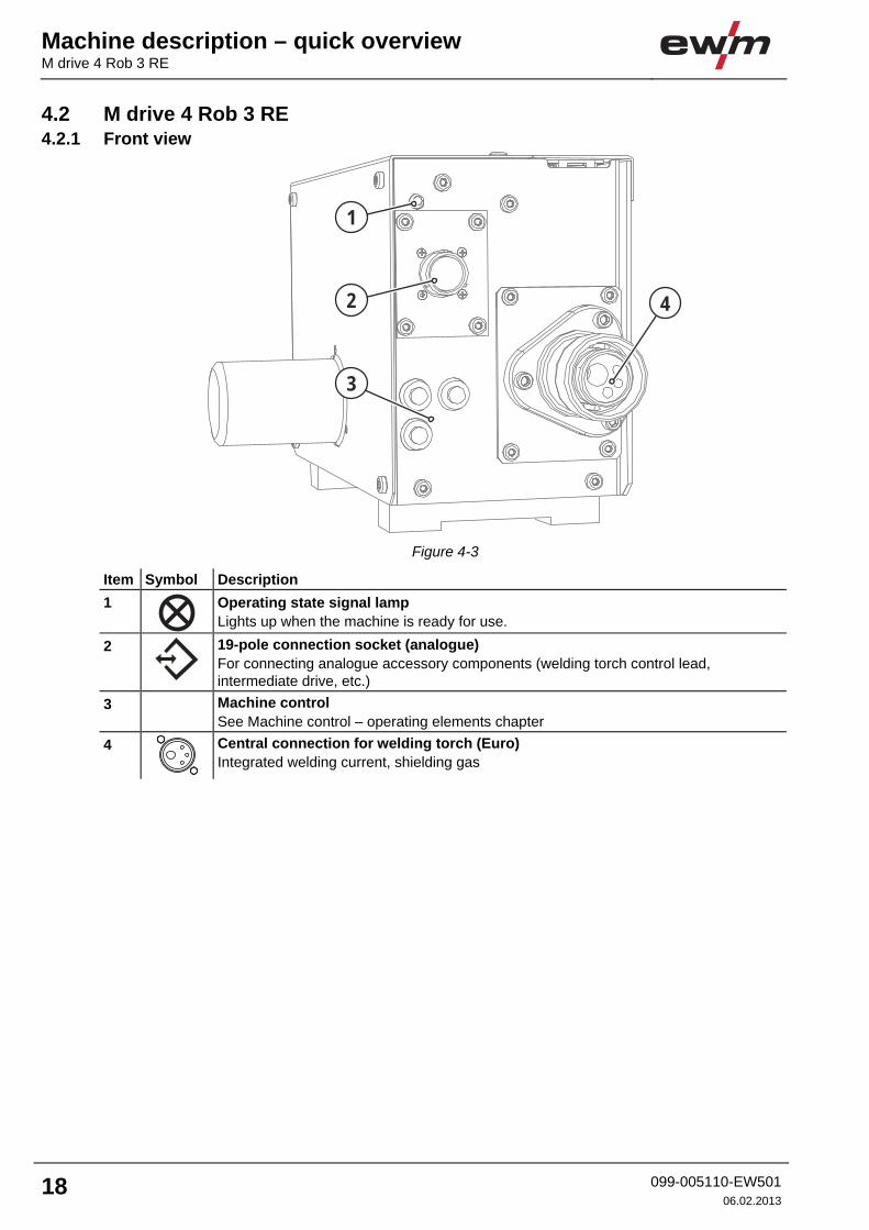
4.2 M drive 4 Rob 3 RE 4.2.1 Front view
3
42
1
Figure 4-3
Item Symbol Description 0 1
Operating state signal lamp Lights up when the machine is ready for use.
2
19-pole connection socket (analogue) For connecting analogue accessory components (welding torch control lead, intermediate drive, etc.)
3 Machine control See Machine control – operating elements chapter
4
Central connection for welding torch (Euro) Integrated welding current, shielding gas
Machine description – quick overview
M drive 4 Rob 3 RE
099-005110-EW501 06.02.2013
19
4.2.2 Rear view
5
1
4
3
2
Figure 4-4
Item Symbol Description 0 1 Wire inlet adapter plate
Adapter plate for various wire inlets 2
Connecting nipple G¼, shielding gas connection
3
analog
12-pole connection socket (analogue) Connection socket for analogue control signals (collision protection, etc. ) between the welding torch and the power source
4
Connector plug, welding current "+" Welding current connection on wire feed unit
5 digital
7-pole connection socket (digital) Wire feed unit connection
Machine description – quick overview Machine control – Operating elements
20 099-005110-EW50106.02.2013
4.3 Machine control – Operating elements
3
21
Figure 4-5
Item Symbol Description 0 1
Wire return key button The welding wire is returned by the torch nozzle. The return speed increases the longer the button is pressed.
2
Wire inching key button For inching the wire electrode when changing wire spools (wire inching begins with a speed of 1.0 m/min for 2 s. It is subsequently increased to 6.0 m/min in 10 s with a ramp function.) The welding wire is inched into the tube package with the current off and without the gas being expelled.
3
Gas test button To check and set the gas flow volume. After activating, the gas flows for 20 s. If the button is pressed again within these 20 s, the gas flow is interrupted.
Design and function
General
099-005110-EW501 06.02.2013
21
5 Design and function 5.1 General
WARNING
Risk of injury from electric shock! Contact with live parts, e.g. welding current sockets, is potentially fatal! • Follow safety instructions on the opening pages of the operating instructions. • Commissioning may only be carried out by persons who have the relevant expertise of
working with arc welding machines! • Connection and welding leads (e.g. electrode holder, welding torch, workpiece lead,
interfaces) may only be connected when the machine is switched off!
CAUTION
Insulate the arc welder from welding voltage! Not all active parts of the welding current circuit can be shielded from direct contact. To avoid any associated risks it is vital for the welder to adhere to the relevant safety regulations. Even low voltages can cause a shock and lead to accidents. • Wear dry and undamaged protective clothing (shoes with rubber soles/welder's gloves
made from leather without any studs or braces)! • Avoid direct contact with non-insulated connection sockets or connectors! • Always place torches and electrode holders on an insulated surface!
Risk of burns on the welding current connection! If the welding current connections are not locked, connections and leads heat up and can cause burns, if touched! • Check the welding current connections every day and lock by turning in clockwise direction,
if necessary.
Risk of injury due to moving parts! The wire feeders are equipped with moving parts, which can trap hands, hair, clothing or tools and thus injure persons! • Do not reach into rotating or moving parts or drive components! • Keep casing covers or protective caps closed during operation!
Risk of injury due to welding wire escaping in an unpredictable manner! Welding wire can be conveyed at very high speeds and, if conveyed incorrectly, may escape in an uncontrolled manner and injure persons! • Before mains connection, set up the complete wire guide system from the wire spool to the
welding torch! • Remove the pressure rollers from the wire feeder if no welding torch is fitted! • Check wire guide at regular intervals! • Keep all casing covers or protective caps closed during operation!
Risk from electrical current! If welding is carried out alternately using different methods and if a welding torch and an electrode holder remain connected to the machine, the open-circuit/welding voltage is applied simultaneously on all cables. • The torch and the electrode holder should therefore always be placed on an insulated
surface before starting work and during breaks.
Design and function Installation
22 099-005110-EW50106.02.2013
CAUTION
Damage due to incorrect connection! Accessory components and the power source itself can be damaged by incorrect connection! • Only insert and lock accessory components into the relevant connection socket when the
machine is switched off. • Comprehensive descriptions can be found in the operating instructions for the relevant
accessory components. • Accessory components are detected automatically after the power source is switched on.
Using protective dust caps! Protective dust caps protect the connection sockets and therefore the machine against dirt and damage. • The protective dust cap must be fitted if there is no accessory component being operated
on that connection. • The cap must be replaced if faulty or if lost!
NOTE
Observe documentation of other system components when connecting!
5.2 Installation
DANGER
Electric shock! The casing on the wire feed unit robot must not have any electrically conductive connection to the protective conductor or to the robot (casing). • Do not remove the rubber feet on the wire feed unit during assembly.
NOTE
There is the option of securing the wire feed with or without carrier plate. The carrier plate is optional.
Design and function
Installation
099-005110-EW501 06.02.2013
23
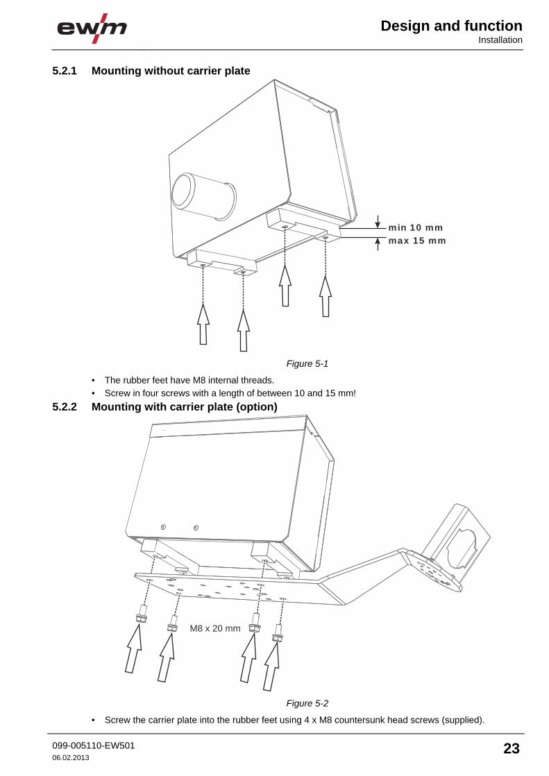
5.2.1 Mounting without carrier plate
min 10 mm
max 15 mm
Figure 5-1
• The rubber feet have M8 internal threads. • Screw in four screws with a length of between 10 and 15 mm!
5.2.2 Mounting with carrier plate (option)
M8 x 20 mm
Figure 5-2
• Screw the carrier plate into the rubber feet using 4 x M8 countersunk head screws (supplied).
Design and function Installation
24 099-005110-EW50106.02.2013
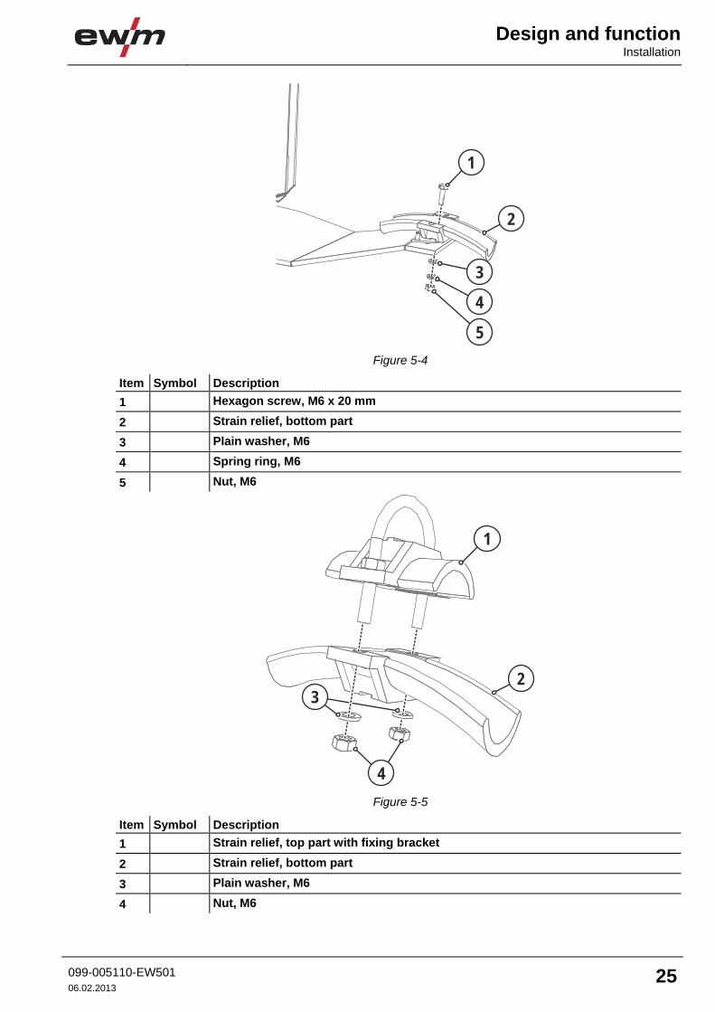
5.2.3 Strain relief option for third party intermediate hose package
NOTE
The mounting plate with the standard strain relief is supplied from the factory as standard.
3
2
1
Figure 5-3
Item Symbol Description 0 1 Anti-twist device
2 Carrier plate
3 Screw, M4 x 16 mm
Design and function
Installation
099-005110-EW501 06.02.2013
25
4
3
2
1
5 Figure 5-4
Item Symbol Description 0 1 Hexagon screw, M6 x 20 mm
2 Strain relief, bottom part
3 Plain washer, M6
4 Spring ring, M6
5 Nut, M6
4
3
2
1
Figure 5-5
Item Symbol Description 0 1 Strain relief, top part with fixing bracket
2 Strain relief, bottom part
3 Plain washer, M6
4 Nut, M6
Design and function Intermediate hose package connection
26 099-005110-EW50106.02.2013
5.3 Intermediate hose package connection 5.3.1 M drive 4 Rob 3 LI
6
7
4
3
2
5
1
Figure 5-6
Item Symbol Description 0 1 Power source
2 Intermediate hose package
3
Connecting nipple G¼, shielding gas connection
4
analog
12-pole connection socket (analogue) Connection socket for analogue control signals (collision protection, etc. ) between the welding torch and the power source
5
Connector plug, welding current "+" Welding current connection on wire feed unit
6 digital
7-pole connection socket (digital) Wire feed unit connection
7 Wire inlet adapter plate Adapter plate for various wire inlets
• Insert 7-pole cable plug on the control lead into the 7-pole (digital) connection socket and secure with crown nut (the plug can only be inserted into the connection socket in one position).
• Insert the 12-pole plug of the control cable into the 12-pole connection socket and secure with the crown nut.
• Screw the gas hose connection nipple onto the G¼" connection nipple. • Push the welding current cable socket onto the “welding current connecting plug” and lock by turning
to the right.
NOTE
When using an external strain relief, pay attention to the additional information provided by the manufacturer.
Design and function
Intermediate hose package connection
099-005110-EW501 06.02.2013
27
5.3.2 M drive 4 Rob 3 RE
6
7
4
3
2
5
1
Figure 5-7
Item Symbol Description 0 1 Power source
2 Intermediate hose package
3
Connecting nipple G¼, shielding gas connection
4
analog
12-pole connection socket (analogue) Connection socket for analogue control signals (collision protection, etc. ) between the welding torch and the power source
5
Connector plug, welding current "+" Welding current connection on wire feed unit
6 digital
7-pole connection socket (digital) Wire feed unit connection
7 Wire inlet adapter plate Adapter plate for various wire inlets
• Insert 7-pole cable plug on the control lead into the 7-pole (digital) connection socket and secure with crown nut (the plug can only be inserted into the connection socket in one position).
• Insert the 12-pole plug of the control cable into the 12-pole connection socket and secure with the crown nut.
• Screw the gas hose connection nipple onto the G¼" connection nipple. • Push the welding current cable socket onto the “welding current connecting plug” and lock by turning
to the right.
NOTE
When using an external strain relief, pay attention to the additional information provided by the manufacturer.
Design and function Welding torch connection
28 099-005110-EW50106.02.2013
5.4 Welding torch connection 5.4.1 M drive 4 Rob 3 LI
2
3
4
1
Figure 5-8
Item Symbol Description 0 1
Welding torch
2 Welding torch hose package
3
19-pole connection socket (analogue) For connecting analogue accessory components (welding torch control lead, intermediate drive, etc.)
4
Euro central connection Welding current, shielding gas and torch trigger included
• Insert the central plug for the welding torch into the central connector and screw together with crown nut.
• Insert the 19-pole torch control lead plug into the 19-pole connection socket (analogue) and lock.
Design and function
Welding torch connection
099-005110-EW501 06.02.2013
29
5.4.2 M drive 4 Rob 3 RE
2
3
4
1
Figure 5-9
Item Symbol Description 0 1
Welding torch
2 Welding torch hose package
3
19-pole connection socket (analogue) For connecting analogue accessory components (welding torch control lead, intermediate drive, etc.)
4
Euro central connection Welding current, shielding gas and torch trigger included
• Insert the central plug for the welding torch into the central connector and screw together with crown nut.
• Insert the 19-pole torch control lead plug into the 19-pole connection socket (analogue) and lock.
Design and function Wire feed
30 099-005110-EW50106.02.2013
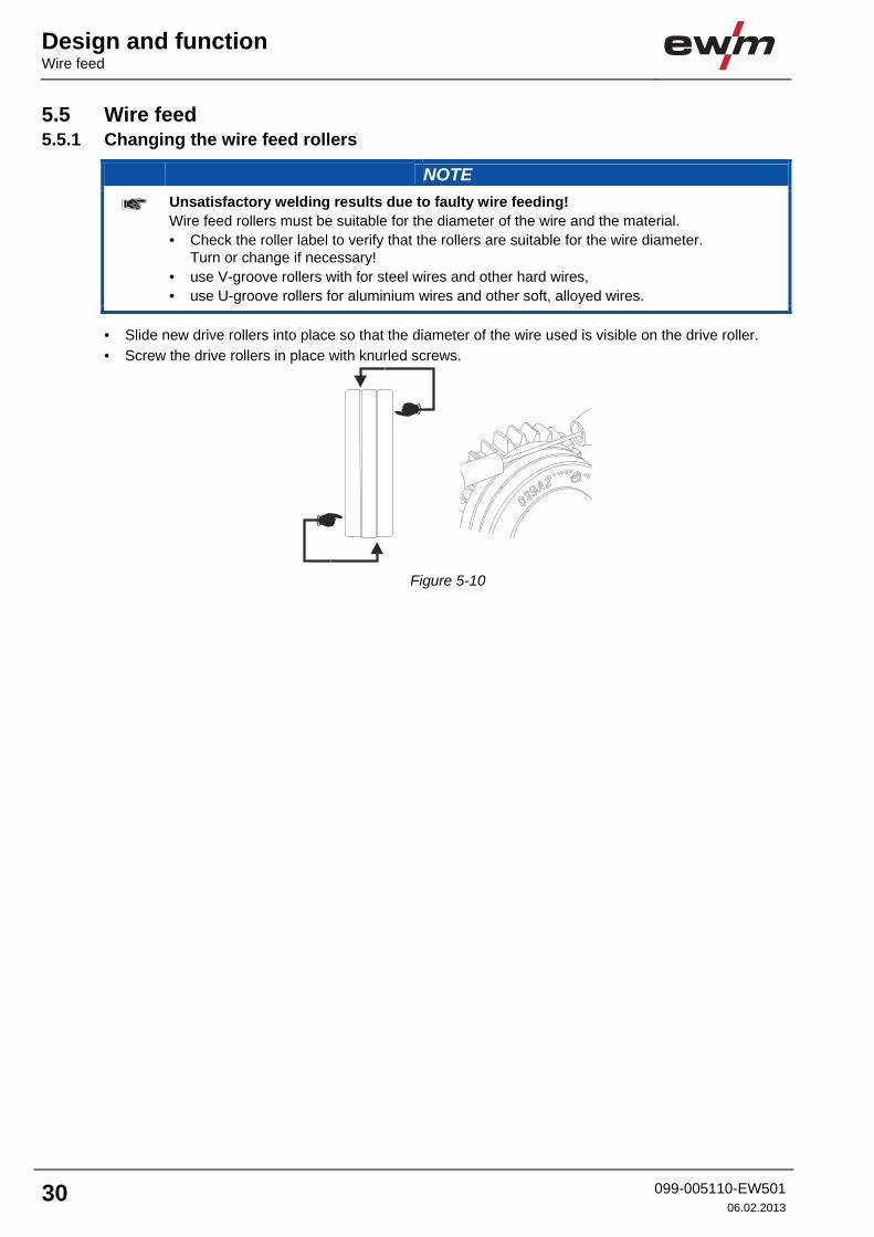
5.5 Wire feed 5.5.1 Changing the wire feed rollers
NOTE
Unsatisfactory welding results due to faulty wire feeding! Wire feed rollers must be suitable for the diameter of the wire and the material. • Check the roller label to verify that the rollers are suitable for the wire diameter.
Turn or change if necessary! • use V-groove rollers with for steel wires and other hard wires, • use U-groove rollers for aluminium wires and other soft, alloyed wires.
• Slide new drive rollers into place so that the diameter of the wire used is visible on the drive roller. • Screw the drive rollers in place with knurled screws.
Figure 5-10
Design and function
Wire feed
099-005110-EW501 06.02.2013
31
5.5.2 Inching the wire electrode
CAUTION
Risk of injury due to moving parts! The wire feeders are equipped with moving parts, which can trap hands, hair, clothing or tools and thus injure persons! • Do not reach into rotating or moving parts or drive components! • Keep casing covers or protective caps closed during operation!
Risk of injury due to welding wire escaping in an unpredictable manner! Welding wire can be conveyed at very high speeds and, if conveyed incorrectly, may escape in an uncontrolled manner and injure persons! • Before mains connection, set up the complete wire guide system from the wire spool to the
welding torch! • Remove the pressure rollers from the wire feeder if no welding torch is fitted! • Check wire guide at regular intervals! • Keep all casing covers or protective caps closed during operation!
Risk of injury due to welding wire escaping from the welding torch! The welding wire can escape from the welding torch at high speed and cause bodily injury including injuries to the face and eyes! • Never direct the welding torch towards your own body or towards other persons!
CAUTION
Extensive wear due to incorrect contact pressure! Incorrect contact pressure will cause extensive wear of the wire feed rollers! • With the adjusting nuts of the pressure units set the contact pressure so that the wire
electrode is conveyed but will still slip through if the wire spool jams. • Set the contact pressure of the front rollers (in wire feed direction) to a higher value!
Design and function Wire feed
32 099-005110-EW50106.02.2013
6
7
4
3
2
1
5
9
8
Figure 5-11
Item Symbol Description 0 1 Adjusting nut
2 Pressure unit
3 Clamping unit
4 Knurled screw
5 Pressure roller
6 Wire feed nipple
7 Guide tube
8 Drive roller
9 Axle
• Extend and lay out the torch hose package. • Unfasten pressure units and fold out (clamping units and pressure rollers will automatically flip
upwards). • Unwind welding wire carefully from the wire spool and insert through the wire inlet nipple over the drive
roller grooves and the guide pipe into the capillary tube and Teflon core using guide pipe. • Press the clamping element with the pressure roller back downwards and fold the wire units back up
again (wire electrode should be in the groove on the drive roller). • Set the contact pressure with the adjusting nuts of the pressure unit. • Press the wire inching button until the wire electrode projects out of the welding torch.
NOTE
The inching speed is infinitely adjustable by simultaneously pressing the wire inching button and turning the wire speed rotary dial. The display shows the selected inching speed.
Design and function
Welding torch/collision protection interface
099-005110-EW501 06.02.2013
33
5.6 Welding torch/collision protection interface
WARNING
Electric shock! Cables must only be connected when the machine is switched off and disconnected from the power supply. • When using a cable screen it should be connected to the wire feed unit only. • The maximum current/voltage load for the contacts is 500 mA/42 V.
stromloser DV 2
Notaus 2
Notaus 3
stromloser DV 1
Gasdüsensensor 2
Gasdüsensensor 1
Notaus 1
PE
Motor extern
codiert
0V1
Einfädeln
Gastest
0VAC
Kontaktsensor
Messsensor UDraht
Motor extern
Motor-
Motor+
K
L
J
H
G
P
N
M
U
S
R
T
V
C
F
D
E
A
B
X1-
stromloser DV 2
Notaus 2
Notaus 3
stromloser DV 1
Gasdüsensensor 2
Gasdüsensensor 1
Notaus 1
PE
Motor extern
codiert
0V1
Einfädeln
Gastest
0VAC
Messsensor UDraht
Motor extern
Motor-
Motor+
K
L
J
H
G
P
N
M
U
S
R
T
V
C
F
D
E
A
B
X1-
Figure 5-12
Item Symbol Description 0 1 Connection socket, 19-pole
Design and function Welding torch/collision protection interface
34 099-005110-EW50106.02.2013
Pin Signal type Description Description
A Input PE dyn. Cable screen
B Input Emergency stop 1 Example, can be otherwise assigned
C Input Emergency stop 2 Example, can be otherwise assigned
D Input Emergency stop 3 Example, can be otherwise assigned
I Input Gas nozzle sensor 1 Example, can be otherwise assigned
F Input Gas nozzle sensor 2 Example, can be otherwise assigned
G Input No-power WF 1 Example, can be otherwise assigned
H Input No-power WF 2 Example, can be otherwise assigned
J Input Measurement sensor Uwire
Example, can be otherwise assigned
K Input Contact sensor Example, can be otherwise assigned
L Output 0V AC
M Output Gas test Gas test key button (make contact with pin L)
N Output Inching Inching key button (make contact with pin P)
P Output 0V
R Protection against the accidental plugging in of a remote control
S nc
T nc
U Output Motor- Supply voltage for Push/Pull "-"
V Output Motor+ Supply voltage for Push/Pull "+"
NOTE
All connections described as "Example, can be freely assigned" can be modified to the customer’s requirements. The suggestions in the table should be observed as closely as possible in this process. (Keep these connection diagrams with the machine documentation!)
Maintenance, care and disposal
General
099-005110-EW501 06.02.2013
35
6 Maintenance, care and disposal
DANGER
Risk of injury from electric shock! Cleaning machines that are not disconnected from the mains can lead to serious injuries! • Disconnect the machine completely from the mains. • Remove the mains plug! • Wait for 4 minutes until the capacitors have discharged!
6.1 General When used in the specified environmental conditions and under normal operating conditions, this machine is largely maintenance-free and requires a minimum of care. There are some points, which should be observed, to guarantee fault-free operation of your welding machine. Among these are regular cleaning and checking as described below, depending on the pollution level of the environment and the length of time the unit is in use.
6.2 Maintenance work, intervals
CAUTION
Electric current! Repairs may only be carried out by authorised specialist staff! • Do not remove the torch from the tube package! • Never clamp the torch body in a vice or similar, as this can cause the torch to be irreparably
destroyed! • If damage occurs to the torch or to the tube package which cannot be corrected as part of
the maintenance work, the entire torch must be returned to the manufacturer
6.2.1 Daily maintenance tasks • Check that all connections and wearing parts are hand-tight and tighten if necessary. • Check that all screw and plug connections and replaceable parts are secured correctly, tighten if
necessary. • Remove any spatter. • Clean the wire feed rollers on a regular basis (depending on the degree of soiling).
6.2.1.1 Visual inspection • Check hose package and power connections for exterior damage and replace or have repaired by
specialist staff as necessary! • Mains supply lead and its strain relief • Gas tubes and their switching equipment (solenoid valve) • Other, general condition
6.2.1.2 Functional test • Check correct mounting of the wire spool. • Welding current cables (check that they are fitted correctly and secured) • Gas cylinder securing elements • Operating, message, safety and adjustment devices (Functional test)
• Casing damage (front, rear and side walls) • Wheels and their securing elements • Transport elements (strap, lifting lugs, handle) • Check coolant tubes and their connections for impurities
6.2.2.2 Functional test • Selector switches, command devices, emergency stop devices, voltage reducing devices, message
and control lamps • Check that the wire guide elements (inlet nipple, wire guide tube) are fitted securely.
6.2.3 Annual test (inspection and testing during operation)
NOTE
The welding machine may only be tested by competent, capable personsl. A capable person is one who, because of his training, knowledge and experience, is able to recognise the dangers that can occur while testing welding power sources as well as possible subsequent damage and who is able to implement the required safety procedures.
For further information, please see the accompanying supplementary sheets "Machine and Company Data, Maintenance and Testing, Warranty"!
A periodic test according to IEC 60974-4 "Periodic inspection and test" has to be carried out. In addition to the regulations on testing given here, the relevant local laws and regulations must also be observed.
6.3 Maintenance work
DANGER
Do not carry out any unauthorised repairs or modifications! To avoid injury and equipment damage, the unit must only be repaired or modified by specialist, skilled persons! The warranty becomes null and void in the event of unauthorised interference. • Appoint only skilled persons for repair work (trained service personnel)!
Repair and maintenance work may only be performed by qualified authorised personnel; otherwise the right to claim under warranty is void. In all service matters, always consult the dealer who supplied the machine. Return deliveries of defective equipment subject to warranty may only be made through your dealer. When replacing parts, use only original spare parts. When ordering spare parts, please quote the machine type, serial number and item number of the machine, as well as the type designation and item number of the spare part.
Maintenance, care and disposal
Disposing of equipment
099-005110-EW501 06.02.2013
37
6.4 Disposing of equipment
NOTE
Proper disposal! The machine contains valuable raw materials, which should be recycled, and electronic components, which must be disposed of. • Do not dispose of in household waste! • Observe the local regulations regarding disposal!
6.4.1 Manufacturer's declaration to the end user • According to European provisions (guideline 2002/96/EG of the European Parliament and the Council
of January, 27th 2003), used electric and electronic equipment may no longer be placed in unsorted municipal waste. It must be collected separately. The symbol depicting a waste container on wheels indicates that the equipment must be collected separately. This machine is to be placed for disposal or recycling in the waste separation systems provided for this purpose.
• According to German law (law governing the distribution, taking back and environmentally correct disposal of electric and electronic equipment (ElektroG) from 16.03.2005), used machines are to be placed in a collection system separate from unsorted municipal waste. The public waste management utilities (communities) have created collection points at which used equipment from private households can be disposed of free of charge.
• Information about giving back used equipment or about collections can be obtained from the respective municipal administration office.
• EWM participates in an approved waste disposal and recycling system and is registered in the Used Electrical Equipment Register (EAR) under number WEEE DE 57686922.
• In addition to this, returns are also possible throughout Europe via EWM sales partners.
6.5 Meeting the requirements of RoHS We, EWM HIGHTEC Welding GmbH Mündersbach, hereby confirm that all products supplied by us which are affected by the RoHS Directive, meet the requirements of the RoHS (Directive 2002/95/EC).
Technical data M drive 4 Rob 3
38 099-005110-EW50106.02.2013
7 Technical data 7.1 M drive 4 Rob 3
NOTE
Performance specifications and guarantee only in connection with original spare and replacement parts!
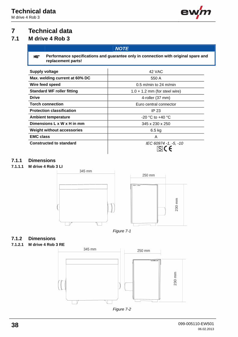
Supply voltage 42 VAC Max. welding current at 60% DC 550 A Wire feed speed 0.5 m/min to 24 m/min Standard WF roller fitting 1.0 + 1.2 mm (for steel wire) Drive 4-roller (37 mm) Torch connection Euro central connector Protection classification IP 23 Ambient temperature -20 °C to +40 °C Dimensions L x W x H in mm 345 x 230 x 250 Weight without accessories 6.5 kg EMC class A Constructed to standard IEC 60974 -1, -5, -10
7.1.1 Dimensions 7.1.1.1 M drive 4 Rob 3 LI
345 mm
23
0 m
m250 mm
Figure 7-1
7.1.2 Dimensions 7.1.2.1 M drive 4 Rob 3 RE
230 m
m
250 mm345 mm
Figure 7-2
Accessories
Options
099-005110-EW501 06.02.2013
39
8 Accessories
NOTE
Performance-dependent accessories like torches, workpiece leads, electrode holders or intermediate hose packages are available from your authorised dealer.
8.1 Options Type Designation Item no. ON COOL W ROB3 Retrofit option, ROB 3 water cooling 092-002384-00000ON 14-POLE WF ROB Retrofit option for 14-pole connection socket with
cable harness 092-001749-00000
ASSEMBLY CONSOLE ROB3 UNIVERSAL
Assembly console for robot wire feed, universal 092-002440-00000
MONTAGE KONSOLE ROB3 2 DV
Mounting console for two robot wire feeds 092-002406-00000
CONNECTOR DRIVE ROB3 WIRE LEAD
Connection set for Connector Drive Rob3 Wire Lead
092-007912-00000
CONNECTOR DRIVE ROB3 W CONDUIT
Connection set for Connector Drive Rob3 W Conduit
092-007916-00000
ROLLINER CONNECTOR DRIVE ROB3
Connection set for Rolliner Connector Drive Rob3 092-007918-00000
Replaceable parts Wire feed rollers
40 099-005110-EW50106.02.2013
9 Replaceable parts
CAUTION
Damage due to the use of non-genuine parts! The manufacturer's warranty becomes void if non-genuine parts are used! • Only use system components and options (power sources, welding torches, electrode
holders, remote controls, spare parts and replacement parts, etc.) from our range of products!
• Only insert and lock accessory components into the relevant connection socket when the machine is switched off.