RESEARCH M EMORAN DUM PRET2LIMINMY WESTIGATION OF DYNAMIC LATERAL STABILITY K Y a r 3 2 a < a K E L 0 a i 3 AMERICAN X-15 RES= I By MartinT. Mod Langley Aeronautical Laboratory Langley Field, Va. c MATIONAL ADVISORY COMMITTEE FOR AERONAUTICS WASHINGTON February 8, 1957 Heclassified December 3, 1958 1 b https://ntrs.nasa.gov/search.jsp?R=19650003117 2018-09-16T06:36:20+00:00Z
Transcript
RESEARCH M EMORAN DUM
PRET2LIMINMY WESTIGATION OF DYNAMIC LATERAL STABILITY
PRELIMINARY INVESTIGATION OF DYNAMIC LATERAL STABILITY
CHARACTERISTICS OF A CONFIGURATION OF TEIE NORTH
AMERICAN x-15 RESEARCH AIRPLANE
By M a r t i n T. Moul
SUMMARY
A preliminary theoret ical investigation has been made t o determine the dynamic l a t e r a l s t a b i l i t y characterist ics of a configuration of the North American X - 1 5 research airplane. O f specific concern were charac- t e r i s t i c modes, period and damping, airplane response t o yaw and r o l l controls, r a t i o of r o l l t o s idesl ip in the Dutch-roll osci l la t ion, and the roll-coupling problem.
Results are presented fo r a Mach number of 6.86, a l t i tudes of 100,000, 150,000, and 200,000 fee t , and angles of a t tack of 0’ and 1 6 O . Configurations with speed brakes closed and f u l l y open were investigated and two intermediate cases, which may represent pa r t i a l ly opened speed brakes, were also included. Roll-coupled motions were noted for an a l t i - tude of 100,000 f e e t with ei ther yaw or roll controls operative. Large rol l - to-s idesl ip ra t ios , ro l l ing sensi t ivi ty t o yaw inputs, and roll coupling resul t ing from yaw inputs were noted for an angle of attack of Oo and could be alleviated by reducing the effect ive dihedral
INTRODUCTION
A program has been in i t i a t ed a t the Langley Laboratory t o investi- gate analyt ical ly the dynamic s t ab i l i t y and cont ro l lab i l i ty of the North American X-15 research airplane f o r t h e proposed flight plans. Dynamic longitudinal and l a t e r a l s t a b i l i t y characterist ics, response of the a i r - plane t o control inputs, and ab i l i ty of a p i l o t t o control the airplane w i l l be investigated i n the program.
A preliminary study has been made t o determine the nature of the dynamic l a t e r a l behavior of the airplane a t high speeds and a l t i tudes where aerodynamic damping i s poor. Aerodynamic character is t ics of the airplane obtained from t e s t s i n the Langley 11-inch hypersonic tunnel
f o r two speed-brake posit ions were u t i l i zed . binations of C and C z , which may represent some other brake posi-
t ions, were selected . In addition two other com-
nP P w
Conditions of the investigation a re a Mach number of 6.86, a l t i t udes of 100,000, l5O,OOO, and 200,000 f ee t , and angles of a t tack of 0' and 160, Results presented are period and damping of the la teral modes, rol l - to- s idesl ip r a t io , and three- and five-degree-of-freedom responses t o ro l l ing- and yawing-moment inputs.
SYMEOLS
coeff ic ients of l a t e ra l - s t ab i l i t y charac te r i s t ic equation
complex roots of l a t e ra l - s t ab i l i t y charac te r i s t ic equation
wing span, ft
w e i g h t coefficient, - W qs
Rolling moment qSb
rolling-moment coefficient,
Yawing moment qSb
yawing-moment coeff ic ient ,
side-force coeff ic ient , Side force
a l t i tude , f t
moment of i ne r t i a about pr incipal X-axis, slug-ft2
moment of i ne r t i a about pr incipal Y-axis, slug-ft2
mament of i ne r t i a about pr incipal Z-axis, slug-ft2
qs
nondimensional radius of gyration i n roll about s t a b i l i t y -- - - . . - ~
x-axis, JKiTGZ; + 3 'sin27 XO 0
nondimensional radius of gyration i n r o l l about pr incipal X-axis, /-
... 0 . 0 0 0
NACA RM ~56127
KZ
M
m
P
r
S
T1/2
W
v
a
P
Y
6a
b-
E
nondimensional radius of gyration i n yaw about s t a b i l i t y ‘cos2q + K%*sin2q
noniimensionai rari ius UT Wyration i n yaw tt’uuut principai
A three-view drawing of the airplane is given in figure 1 and the geometric and i ne r t i a characterist ics pertinent t o t h i s study, in table I.
For t h i s investigation, the yaw and roll reaction controls of the airplane were assumed t o be in use. The roll control produces 17 pounds th rus t and a ro l l ing moment of 120 foot-pounds, and the yaw control pro- duces 90 pounds thrust and a yawing moment of 2,275 foot-pounds. For a l t i tudes of 100,000 and 200,000 feet , the moment coefficients of the react ion controls, control-effectiveness estimates f o r the airplane aero- dynamic controls, and the equivalent aerodynamic-control deflections are given in the following table. deflections are valid f o r the conditions t h a t the ailerons and rudder produce no cross or couplinef moments.
These equivalent aerodynamic-control
Reaction controls are intended as a l te rna te controls f o r use a t low dynamic pressures where aerodynamic controls a re ineffective. The equiva- l en t aerodynamic-control deflections in the preceding tab le indicate t h a t rudder and aileron would be in use a t an a l t i t ude of 100,OOO fee t , whereas reaction controls would be used a t 200,000 f ee t .
Data from model t e s t s of a configuration of t he North American X-15 research airplane i n the Langley 11-inch hypersonic tunnel are presented i n figure 2 for two speed-brake configurations, brakes closed and open 45' (configurations 1 and 4, respectively). Since the brakes- closed configuration is directionally unstable, two other values of C
and C z B
two intermediate brake configurations (configurations 2 and 3).
"$ were selected for the purpose of t h i s analysis and may represent
The
sidesl ip derivatives of the t e s t models and the two selected intermediate brake configurations a re summarized i n tab le I1 f o r angles of attack of 00 and 160.
ANALYSIS
Characteristic Equation
In t h i s investigation an a l t i tude range (100,000 t o 200,000 f e e t ) was selected f o r which aerodynamic damping was expected t o be poor and rotary derivatives could be neglected. Under these conditions a p i l o t w i l l experience unusual d i f f icu l ty i n controll ing the airplane.
The l a t e r a l equations of motion f o r a stabil i ty-axes system are, when rotary derivatives are neglected,
!The modes represented by equation (2) a re an osci l la tory (Dutch roll) mode and an aperiodic mode. s t ab i l i t y characterist ic equation obtained when rotary derivatives a re included, it i s seen tha t the normal sp i r a l root is zero fo r t h i s simpli- f i ed condition. The aperiodic root obtained for the simplified condition i s related t o the usual damping-in-roll mode but is much smaller because
By comparison with the general l a t e ra l -
i s assumed t o be equal t o zero. czP
. NACA RM L56~27 .
L
Approximations t o the Roots
7
The character is t ic roots may be quickly and accurately determined from approximate factors of the characterist ic equation when rotary derivatives are neglected. The general character is t ic equation
( 3 ) Ah3 + Bh2 + Ch + D = 0
can be written as
where A 1 and (-a ? io) are the actual roots. The approximations t o the roots a re
Roll-to -Sideslip Rat i o
I
Simplified expressions which yield accurate values of the $//3 r a t i o f o r these a l t i tudes when rotary derivatives a re neglected can be determined.
For a = Oo only the rolling-moment equation must be considered.
o r
NACA RM ~ 3 6 ~ 2 7
For the Dutch roll root, the r e a l par t i s negligible ,-I comparison with the imaginary par t , and
Then
For a = 1 6 O , two equations must be considered because of principal- axis-inclination effect . A simple expression for @/j3 resu l t s when the rol l ing- and yawing-moment equations are used:
from which
Again neglecting the r e a l par t of the Dutch roll root,
A2 = - (K&lp + KxzCZp)
2pb(KX2Kz2 - K Z 2 )
and
. L NACA RM ~ 5 6 ~ 2 7 . 9
RESULTS AND DISCUSSION
Results are Fresented of stability-boundary plots , roots of charac- t e r i s t i c equation, and roll-to-sideslip r a t i o t o show lateral s t a b i l i t y character is t ics and of time his tor ies of motions t o show response charac- t e r i s t i c s and ine r t i a coupling possibi l i t ies .
Stability-Boundary Plots
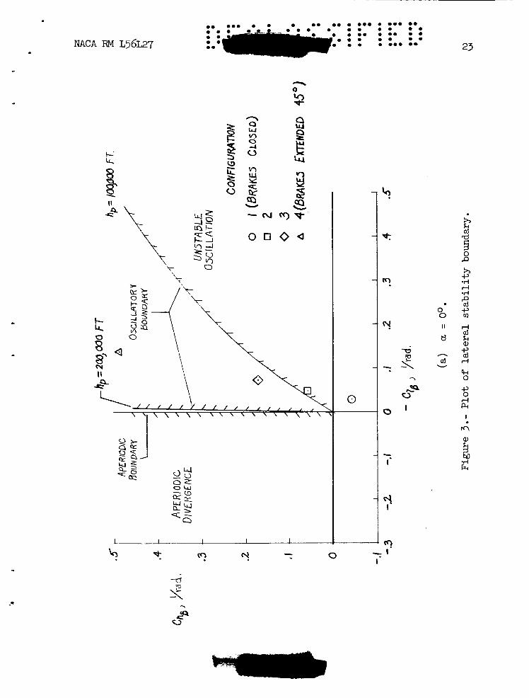
Stability-boundary p lo ts were constructed t o determine regions of osci l la tory and aperiodic s t a b i l i t y in terms of weathercock s t a b i l i t y
and effect ive dihedral C z In the absence of aerodynamic-damping derivatives, the only aerodynamic characterist ic contributing damping is CyB. and two al t i tudes, 100,000 and 200,000 fee t . the condition fo r neutral damping of the osc i l la t ion and i s determined from Routh's discriminant (E - AD = 0). boundary the osci l la t ion i s unstable. The aperiodic boundary i s the condi- t i on which ex is t s when the aperiodic root is equal t o zero and is defined by D (coefficient of characterist ic equation) = 0. The cross-hatched s ide of t h i s curve denotes a divergent aperiodic mode. The region of complete s t a b i l i t y is located between the oscil latory and aperiodic boundaries. A thorough discussion of boundary plots i s given in reference 1.
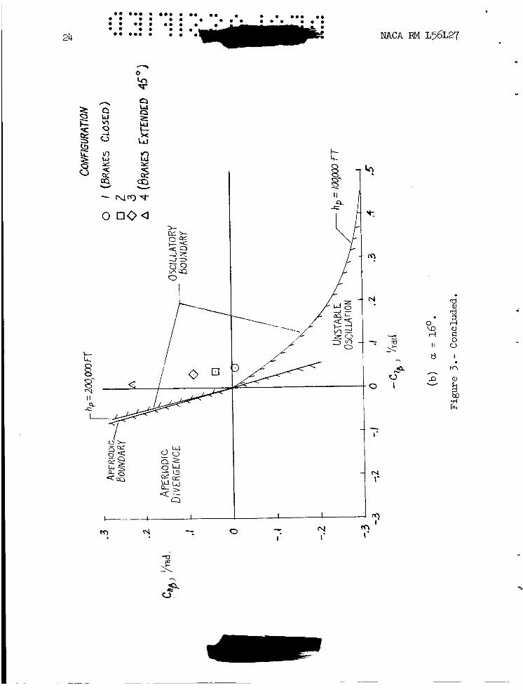
CnP P ' Figure 3 presents the resu l t s fo r two angles of attack, 0' and 160,
The osci l la tory boundary i s
On the cross-hatched side of the
For an angle of a t tack of Oo (fig. 3(a)) and an a l t i t ude of 200,000 f ee t , the airplane has an unstable osc i l la t ion for posit ive effec- t i v e dihedral except fo r a small stable region a t small negative values. Cnp and C z p values f o r which the airplane would be s table . A s the angle of a t tack i s increased t o 1 6 O ( f ig . 3 ( b ) ) , the osc i l la tory boundary rotates clockwise fo r an a l t i t ude of 100,000 f e e t and the s tab le region takes in the whole f irst quadrant and a portion of the fourth quadrant (negative Cnp). axis inclination. For an a l t i tude of 200,000 feet, inclination of the pr incipal axis causes the oscil latory boundary t o s h i f t counterclockwise in to the second quadrant. The difference i n the e f f ec t of principal- axis inclination for the two alt i tudes i s a t t r ibu ted t o the term Cw cos 7 KxzCnP i n the D coefficient of equation (3).
tude of 200,000 f e e t the larger value (3.54) of c ient , causes t h i s counterclockwise rotat ion of the osci l la tory boundary.
czB For an a l t i tude of 100,000 f e e t there is a large region of
This shif t ing of the boundary is the expected e f fec t of principal-
For an a l t i -
Cw, the w e i g h t coeffi-
The brakes-closed (configuration 1) , brakes open (configuration 4), and the two intermediate brake configurations (configurations 2 and 3 )
NACA RM ~ 3 6 ~ 2 7
* I
and C2 values. The CnP P are located i n figure 3 a t the appropriate brakes-closed configuration i s divergent a t but i s completely s table a t a = 1 6 O as a resu l t of principal-axis inclination. The brakes- open configuration a t both angles Of a t tack i s completely s table a t an al t i tude of 100,000 f e e t but has an unstable Dutch roll osc i l la t ion a t an al t i tude of 200,000 fee t .
.\ a = 0'
Characteristic Roots
The roots of the character is t ic equation were determined f o r the con- figurations indicated i n figure 3 f o r a l t i tudes of 100,000, 150,000, and 200,000 f ee t . The resu l t s a re presented i n tab le I11 as time t o damp t o one-half amplitude fo r both the Dutch roll and aperiodic modes and as period of osci l la t ion for the Dutch roll mode.
The tabulated character is t ics a re i n agreement with the qual i ta t ive resu l t s indicated by the stability-boundary p lo ts . The aperiodic mode i s always stable. The period of osc i l la t ion increases by a factor of 7 f o r an increase i n a l t i tude from 100,000 t o 200,000 f e e t as a r e su l t of a decrease in dynamic pressure. The e f fec t of changing the fl ight-path angle t o -6oO from Oo i s negligible. 7
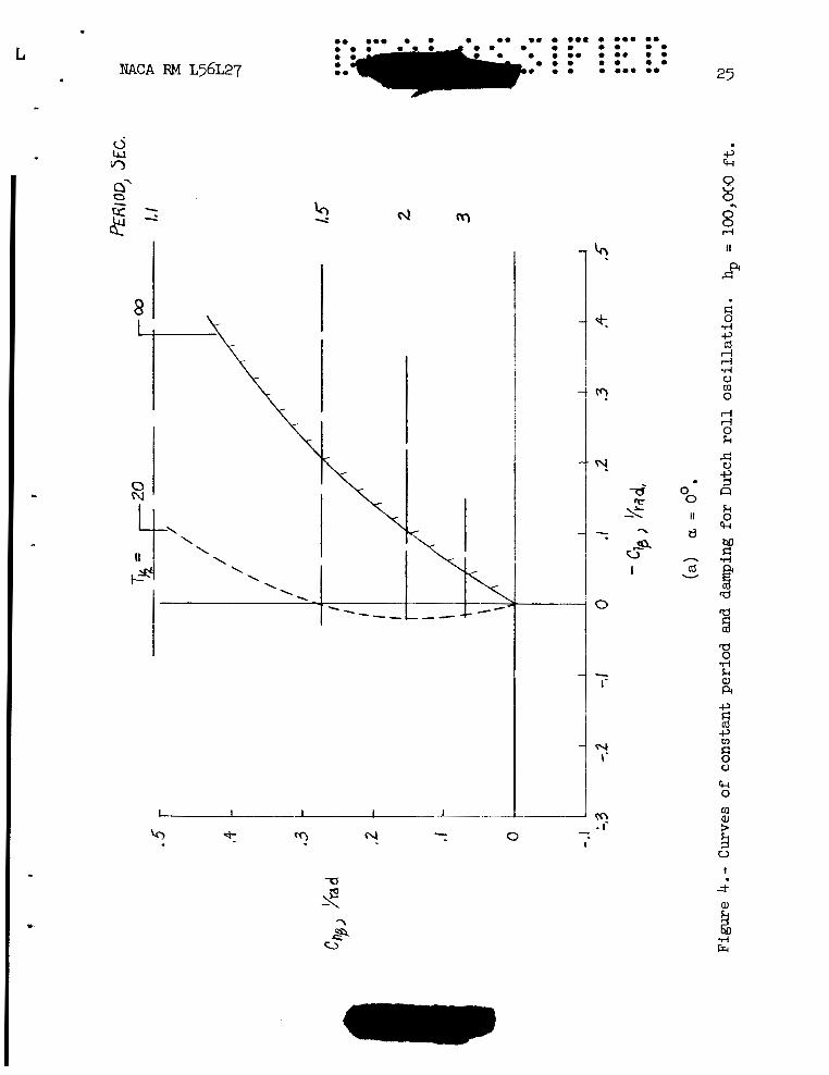
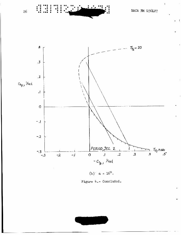
In f igure 4, curves of constant period and damping of the Dutch roll osci l la t ion are presented for angles of a t tack of 00 and 160 and an a l t i - tude of 100,000 f e e t i n terms of weathercock s t a b i l i t y and effect ive dihedral parameters. s t ab i l i t y for an a l t i tude of 100,000 f e e t ( f ig . 3 ) , the constant-damping curves of figure 4 show tha t the Dutch roll osc i l la t ion fo r both a = 0' and 16O i s rea l ly only l igh t ly damped throughout the region of normal values of C and C2 , that is , the f i r s t quadrant. For 200,000 f ee t ,
the airplane was shown in figure 3 t o be unstable throughout the f i r s t quadrant except fo r very small values of effect ive dihedral for
- Although there are large regions of osci l la tory
nP P 0 a = 0 .
A few calculations have been made t o determine the e f fec t of rotary derivatives and constant pitching velocity on the character is t ic modes. During f l i g h t a t high al t i tudes the airplane w i l l be i n a b a l l i s t i c f l i g h t path rather than i n leve l f l i g h t and w i l l experience a constant pitching velocity i f angle of attack i s held constant. For t h i s condition pitching velocity influences l a t e r a l motion through i n e r t i a terms
rolling-moment equations, respectively. For a constant pitching velocity these terms ac t as equivalent i n calculations of the roots fo r 100,000 and l50,OOO fee t . included i n table I11 where the C and C z r values denote t h i s condition
and C2, derivatives and were included The resu l t s a re
of constant pitching velocity. pitching velocity is t o add an increment t o the Dutch roll damping, a decrement t o the aperiodic mode, and to introduce a neutrally s table aperiodic mode.
For both a l t i tudes the e f fec t of constant
Two other calculations were made fo r a l t i tudes of 100,000 a.nd
as well as the constant-pitching-velocity terms were included in 200,000 f e e t in which estimates of the damping derivatives Cnr and
czP the equations of motion. terms have a small e f fec t on period and add an increment t o Dutch roll damping which is not significant, since the osc i l la t ion is only neutrally s table a t best. For 100,000 f e e t the period is unchanged, but the damping of both the Dutch roll and damping-in-roll modes i s appreciably increased by including Znr and C z These resul ts indicate tha t 100,000 f e e t m%y not be a suff ic ient ly high al t i tude fo r which damping derivatives can be neglected. on airplane responses w i l l be discussed i n a later section.
For an a l t i tude of 200,000 f e e t these additional
P'
The effects of damping derivatives and constant pitching
Roll-to-Sideslip Ratio #/p
The #/p r a t i o i n the Dutch roll mode is an important f lying quali ty and has been calculated for the same conf'igurations and conditions for which roots were obtained. The #/$ ra t ios are given i n table IV. Although tolerable values of @/p damping, #/p ra t ios greater than 4 have been found by p i lo t s (ref. 2) t o be generally intolerable regardless of damping. &om the table , it i s noted tha t angle of attack had a large favorable e f fec t on the #/$ r a t i o , the maximum value f o r a = 1 6 O being 3.8 as compared with 15.9 f o r a = 0'. This large reduction i n $/p i s at t r ibuted t o both a reduction i n C z p principal-axis inclination as indicated by the approximate expression, equation (6). Also, the #/p r a t i o i s pract ical ly independent of a l t i - tude. plus Cnr and C z were considered, there was a negligible change i n
$/p ra t ios .
c
r a t io a re dependent on Dutch roll
with increasing angle of attack and the effect of
For two cases i n which constant pitching and constant pitching
P
Time Histories
In flying the airplane i n a high-altitude t ra jectory it w a s assumed t h a t the p i l o t would apply controls so tha t the airplane bank angle would not exceed 90'. l a t e r a l equations of motion were used with an analog computer t o determine airplane response t o an i n i t i a l sideslip angle, yawing-moment input, and rolling-moment input f o r a l t i tudes of 100,000 and 200,000 f e e t and angles
.. For t h i s purpose the l inear three-degree-of-freedom
*
.. 0 . . . ... . ., m. . . . ... .. .. .. 1 - - -
.LL NACA RM ~56~27
-. of attack of 0' and 16O. were also calculated t o determine whether i ne r t i a coupling i s a problem
t ions 1, 2, and 4.
In addition some five-degree-of-freedom motions
a t these speeds and al t i tudes. Time h is tor ies are shown for configura- .\
Response t o an i n i t i a l s ides l ip angle.- The response t o an i n i t i a l s ides l ip angle i s presented i n figure 5 f o r one intermediate brake con- figuration t o i l l u s t r a t e the osci l la tory character is t ics and rol l - to- s ides l ip r a t io discussed previously. The curves show t h a t the period a t 200,000 feet is about seven times as great as the period a t 100,000 f e e t a s discussed previously, the osc i l la t ion i s more unstable a t X)O,OOO fee t , and the $/p r a t i o i s about 15. Although the osc i l la t ion is more unstable a t 200,000 f ee t , as would be expected from the s t a b i l i t y boundary plots , it would appear t o be easier t o control because of the longer period. Consequently, stability-boundary p lo ts should not be re l ied upon solely i n appraising airplane s t a b i l i t y character is t ics since they do not provide quantitative resu l t s . information on the s t ab i l i t y and control character is t ics of the airplane.
Response calculations provide valuable additional
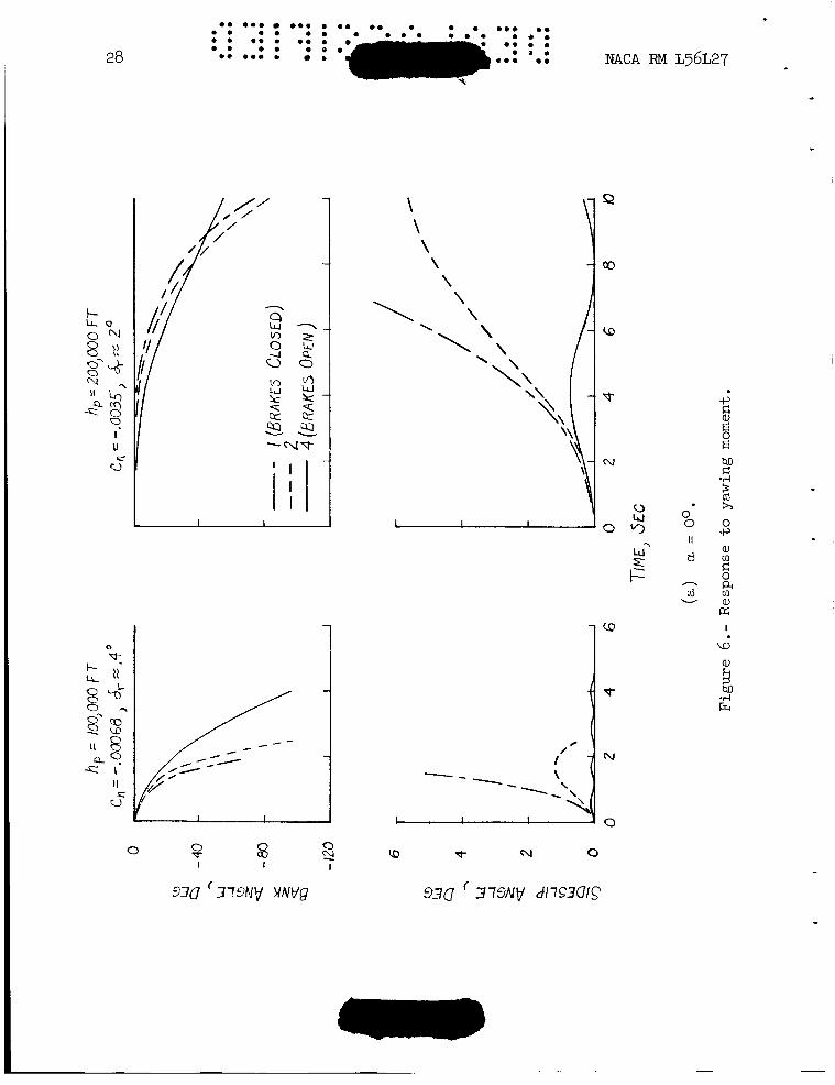
Response t o yawing-moment input.- Figure 6 presents the response i n bank and s idesl ip t o a yawing-moment input for angles of attack of 0' and 16O and a l t i tudes of 100,000 and 200,000 f e e t . control i f no ro l l ing moment is produced) f o r 100,000 f e e t and one-tenth the reaction control (about 2 O aerodynamic control) f o r 200,000 fee t . For a = Oo, the brakes-closed configuration i s unstable and the motions are divergent. The other two configurations have small s ides l ip responses a t 100,000 f e e t but rapid roll responses as a r e su l t of dihedral e f fec t and the large dynamic pressure. a r e larger and the roll responses are slower because of the greatly reduced dynamic pressure. ca l ly stable and the roll response i s slower than fo r of principal-axis-inclination effect . a very slow roll response a t dihedral effect ,
The input i s tha t provided by t h e reaction control (equivalent t o about 0 . 4 O aerodynamic .?
-
A t 200,000 f ee t , the s idesl ip motions
A t a = 16O, the brakes-closed configuration i s s t a t i - a = Oo as a r e su l t
The brakes-open configuration has a = 160 because of the small value of
C z p , shown i n figure 3 (b ) .
Response t o rolling-moment input.- Figure 7 presents the responses t o a rolling-moment input fo r a l t i tudes of 100,000 and 200,000 f e e t and angles of attack of Oo and 160. The inputs were f ive times the ro l l ing moment provided by the reaction control or about O.5O ai leron deflection ( i f no yawing moment i s produced) for an a l t i t ude of 100,000 f e e t and a ro l l i ng moment equal t o the reaction control or about 50 aileron deflec- t ion for an a l t i tude of 200,000 fee t .
A t u = Oo, the brakes-closed configuration i s unstable and the motions are divergent. For large values of s idesl ip angle, the roll direction i s reversed by dihedral effect . A t an a l t i t ude of 200,000 fee t , the roll reversal i s not evident and would not occur u n t i l s ides l ip angles
. become larger. The other configurations fo r a = 0' experience small s ides l ip angles and a ro l l ing moment as expected. -
A t a = 16'. the brakes-open Configuration experiences a small side- s l i p motion and a ro l l ing motion. s table as a r e su l t of principal-axis inclination and the s ides l ip response i s oscil latory. t i on a t both a l t i tudes as a result of negative
The brakes-closed configuration is
However, the r o l l is again reversed fo r this configura- Cnp
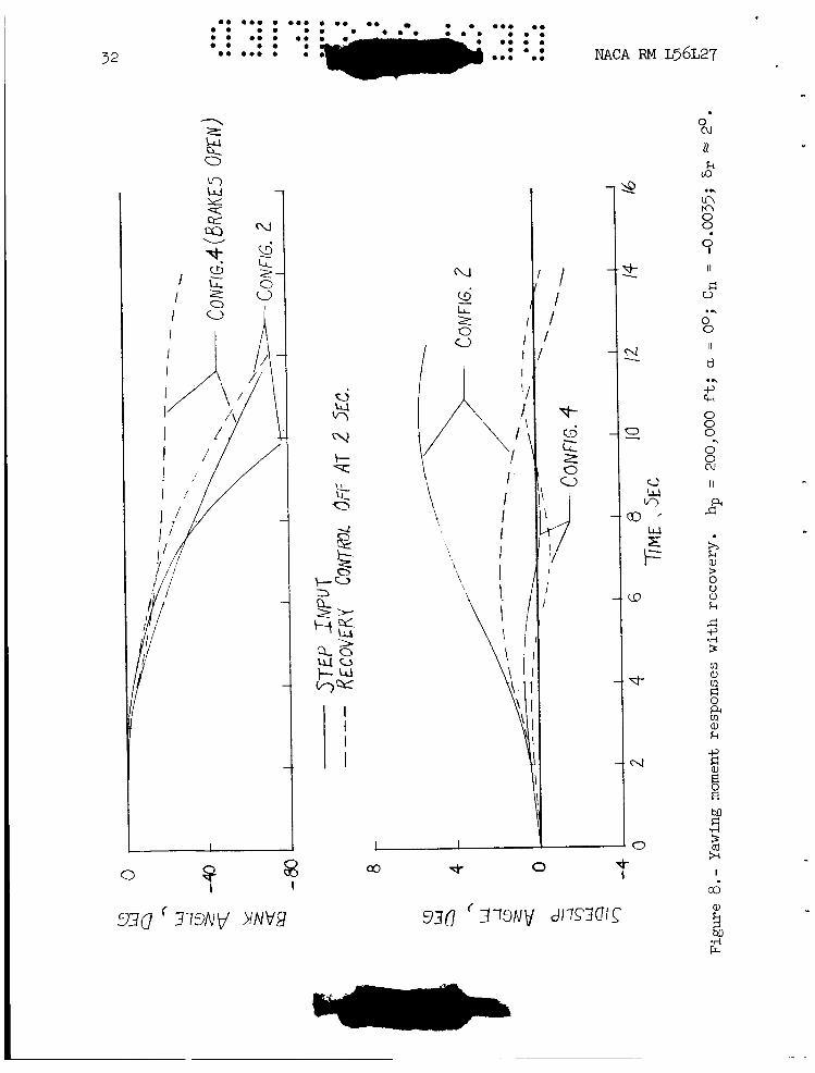
Recovery.- In figures 8 and 9, the e f fec t on airplane motions of holding the control fo r 2 seconds and then neutralizing it i s shown f o r both yawing- and rolling-moment inputs. the airplane osc i l la tes about a Oo sideslip angle but continues ro l l ing in the absence of damping i n r o l l . a i leron would have t o be reversed t o produce a r o l l acceleration of opposite sign.
When the control is neutralized,
h order t o stop the rol l ing, the
r.
c
Effect of rotary derivatives.- The e f fec t of ro ta ry derivatives and constant pitching terms on roots of character is t ic equations has been discussed and was shown t o be appreciable f o r an a l t i t ude of 100,000 fee t . Since the Dutch r o l l and damping-in-roll modes experienced increases i n damping it was desirabjle t o determine the e f fec t of these changes on a i r - plane motions. and 200,000 f e e t and a = 0" fo r the configuration having C = O.Wr( and C z P = -0.049 t o control inputs. changes i n the motions.
A few calculations have been made f o r a l t i tudes of 100,000
nP t o determine the effect of these derivatives on response
For an a l t i tude of 200,000 f e e t there were negligible
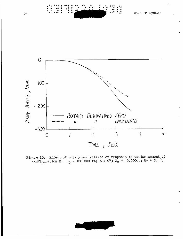
In figure 10, the effect of rotary derivatives on the response i n ba& t o a yawing-moment input i s presented for an a l t i t ude of 100,000 feet. Terms included are the inertia-coupling terms introduced by the pitching velocity experienced i n zero- l i f t f l i gh t (discussed i n the section en t i t l ed "Characteristic Roots") and damping derivatives Cnr = -0.46 and
C z p = -0.21. t o a bank angle of -90'. For maneuvers of longer duration, bank angles beyond -90' i n figure 10, the difference between the curves i s appreci- able, and it appears t ha t in general rotary derivatives should be con- sidered f o r a l t i tudes up t o 100,000 feet . However, rotary derivatives appeared t o have a minor e f fec t on the small motions presented in t h i s paper.
The curves show a minor e f fec t of rotary derivatives up
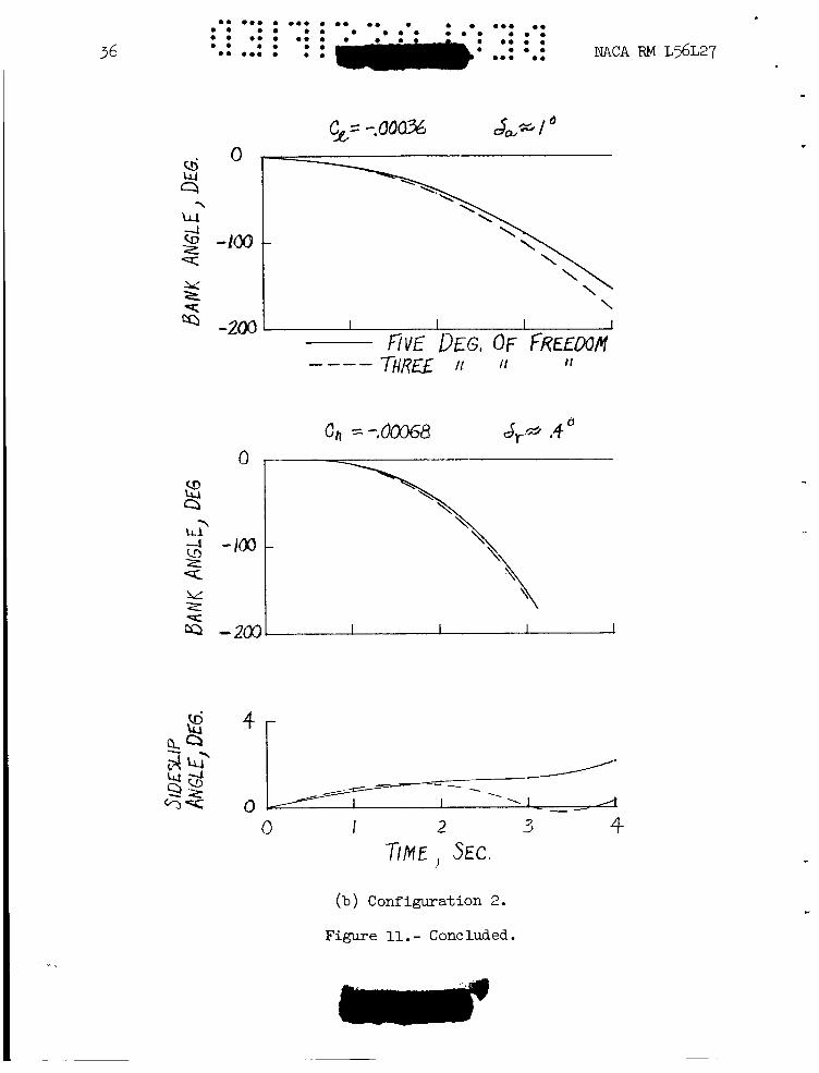
Five-degrees-of-freedom results.- A few five-degree-of-freedom cal- culations have been made fo r configurations 2 and 4 f o r an angle of a t tack of 0' and an a l t i tude of 100,000 fee t . A range of yawing- and rolling-moment inputs varying from the magnitude of the reaction controls t o several degrees of aerodynamic controls w a s considered t o
I, determine the range of va l id i ty of the three-degree-of-freedom analysis and t o investigate the inertia-coupling problem. I n f igure 11, resu l t s
moment 1.0 times as great as t h a t provided by the react ion control, or about 1' ai leron deflection, and a yawing moment equal t o t h a t of t he reaction control or about 0.4O rudder deflection. Only f o r t he in te r - mediate brakes configuration and the yawing-moment input is there a con- siderable difference i n s ides l ip response between t h e three-degree-of- freedom and the five-degree-of-freedom motions fo r these small inputs. The calculated c r i t i c a l ro l l i ng velocity f o r t h i s configuration is 2 radians per second and a t 2.8 seconds the airplane is experiencing t h i s roll ra te . A t the c r i t i c a l roll ra te , inertia-coupling t e r m s i n t he equations are important, and hence the three-degree-of-freedom resu l t s a re invalid. The s ignif icant r e su l t is t h a t t h i s intermediate brakes configuration (small Cnp) can experience roll-coupled motions a t 100,000 fee t fo r small yawing-moment inputs as a r e s u l t of a high roll sens i t iv i ty t o yaw controls.
are presented fo r two configurations fo r which the inputs were a ro l l i ng -\
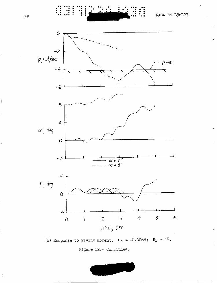
Figure 12 presents r e su l t s fo r t he brakes-open configuration f o r inputs equivalent t o loo ai leron deflection and 4' rudder def lect ion and i n i t i a l angles of a t tack of Oo, 10, and 8'. i s about 4.4 radians per second and i s a function of the p i tch natural frequency fo r t h i s configuration. Figure 12(a) presents t he r e su l t s fo r a rolling-moment input and i l l u s t r a t e s the ef fec t of t he disturbance term pa. For = Oo, no coupled motions a re evident even though -. c r i t i c a l roll r a t e s a re encountered. For = lo, some coupling i s noted and for = 8O considerable motion i n a and p i s noted as the resu l t of the large value of t he pa term.
The c r i t i c a l roll r a t e
9
For the yawing-moment input ( f ig . 12 (b ) ) , more roll coupling i s encountered for + = Oo than for % = 8O. The r o l l r a t e did not approach the c r i t i c a l value f o r a. = 8' because of t he small C l a t
P t h i s a, which decreases the roll sens i t i v i ty t o yawing-moment inputs.
Results f o r configuration 2 a re presented i n f igure 13 fo r inputs of 10' aileron deflection and 4' rudder deflection. input, no coupling e f fec ts a re noted f o r an i n i t i a l a of zero. For an i n i t i a l a. of 8' coupling e f fec ts a re noted. However, the severi ty of t he motions could not be determined because an angular veloci ty exceeded the range provided f o r i n se t t i ng up the problem on an analog computer and caused the computer t o overload before 1 second.
For t he a i le ron
For the same reasons, the motions i n response t o 4' rudder input ( f ig . 13(b) ) d id not continue long enough t o determine t h e i r forms. s ides l ip response a t appears t o be divergent, but it i s noted t o be nothing more than a three-degree-of-freedom response t o a rudder input. However, the rapid increase i n a fo r this case indicates t h a t roll coupling was probably present.
.. The
a = 0'
\
CONCLUSIONS
n-----tL- -0 -- ----I--L:..-~ 4 - - r n n C n o C < r r - AP CLn A r m e r n < - l o+nro l P+O- I\caLLLba V I LLLI b*bc*L **A. L u u r g u u r v r A V I " L A C U J A A U Y - L . . -LU"..* -A Y Y I
b i l i t y character is t ics of a configuration of the North American X-15 research airplane for a Mach number of 6.86 and a l t i tudes of 100,000 and 200,000 fee t , aerodynamic damping derivatives being neglected, indicate tha t
1. Roll-to-sideslip ra t ios were large a t zero angle of a t tack because of large effect ive dihedral Czg.
2. Yawing-moment inputs produced large bank angles and r o l l ra tes a t an a l t i tude of 100,000 fee t .
3 . Although the brakes-closed configuration was s tabi l ized by principal-axis inclination, i t s rol l ing character is t ics a re unsatisfactory in t h a t dihedral e f fec t reverses the roll direction.
4. Roll coupling developed from small rudder inputs a t 100,000 f e e t f o r configurations having small weathercock s t a b i l i t y Cnp and large
B' effect ive dihedral C2
5 . The brakes-open configuration experienced roll coupling a t 100,000 f e e t for both a 10' aileron input and a 4' rudder input.
6. The large rol l - to-s idesl ip r a t io s @/p, ro l l ing sens i t iv i ty t o yaw inputs, and roll coupling result ing from yaw inputs could be a l lev i - ated by reducing the effect ive dihedral C z p -
Langley Aeronautical Laboratory, National Advisory Committee for Aeronautics,
Langley Field, Va., December 10, 1956.
REF”CES
1. Sternfield, Leonard, and Gates, Ordway B., Jr.: A Simplified Method fo r the Determination and Analysis of the Neutral-Lateral-Oscillatory- Stability Boundary. NACA Rep. 943, 1949. (Supersedes NACA TN 1727.)
2. Williams, Walter C., and Phillips, William H.: on the Handling Qualities of Airplanes.
Some Recent Research NACA RM HXL29a, 1 ~ 6 .
3. Phillips, William H.: Effect of Steady Rolling on Longitudinal and Directional Stability. NACA TN 1627, 1948.
L 17
!rAm I
GEDMETRIC AND INERTIA CIIARACTERISTICS OF AIRPLANE