M M 6 6 V V L L Q Q P P r r o o i FCC Information and Copyright This equipment has been tested and found to comply with the limits of a Class B digital device, pursuant to Part 15 of the FCC Rules. These limits are designed to provide reasonable protection against harmful interference in a residential installation. This equipment generates, uses and can radiate radio frequency energy and, if not installed and used in accordance with the instructions, may cause harmful interference to radio communications. There is no guarantee that interference will not occur in a particular installation. The vendor makes no representations or warranties with respect to the contents here of and specially disclaims any implied warranties of merchantability or fitness for any purpose. Further the vendor reserves the right to revise this publication and to make changes to the contents here of without obligation to notify any party beforehand. Duplication of this publication, in part or in whole, is not allowed without first obtaining the vendor’s approval in writing. The content of this user’s manual is subject to be changed without notice and we will not be responsible for any mistakes found in this user’s manual. All the brand and product names are trademarks of their respective companies.
Transcript
MMM666VVVLLLQQQ PPPrrrooo
i
FCC Information and Copyright
This equipment has been tested and found to comply with the limits of a Class B digital device, pursuant to Part 15 of the FCC Rules. These limits are designed to provide reasonable protection against harmful interference in a residential installation. This equipment generates, uses and can radiate radio frequency energy and, if not installed and used in accordance with the instructions, may cause harmful interference to radio communications. There is no guarantee that interference will not occur in a particular installation. The vendor makes no representations or warranties with respect to the contents here of and specially disclaims any implied warranties of merchantability or fitness for any purpose. Further the vendor reserves the right to revise this publication and to make changes to the contents here of without obligation to notify any party beforehand. Duplication of this publication, in part or in whole, is not allowed without first obtaining the vendor’s approval in writing. The content of this user’s manual is subject to be changed without notice and we will not be responsible for any mistakes found in this user’s manual. All the brand and product names are trademarks of their respective companies.
CCCooonnnttteeennnttt
ii
LAYOUT OF M6VLQ PRO .....................................................................1 COMPONENT INDEX .............................................................................2 ENGLISH ...................................................................................................3
M6VLQ Pro Features ................................................................................................. 3 Package contents ...................................................................................................... 4 How to setup Jumper ................................................................................................ 5 CPU Installation ......................................................................................................... 5 DIMM Modules: DIMM1/ DIMM2 ................................................................................ 6 Jumpers, Headers, Connectors & Slots................................................................... 7
Características del M6VLQ Pro............................................................................... 12 Contenido del Paquete............................................................................................ 13 Cómo instalar un Puente......................................................................................... 14 Instalación de la CPU .............................................................................................. 14 Módulos DIMM: DIMM1/ DIMM2 .............................................................................. 15 Puentes, Cabezales, Conectores y Ranuras ......................................................... 16
Introduction.............................................................................................................. 34 System Requirement ............................................................................................... 34 Installation................................................................................................................ 35 Usage........................................................................................................................ 36
TROUBLE SHOOTING.........................................................................44 SOLUCIÓN DE PROBLEMAS .............................................................45
1
Layout of M6VLQ Pro
※NOTE: ●represents the first pin.
2
Component Index
A. Power Source Selection for K. Front USB Header (JUSB1) Keyboard and mouse (JKBV1) L. PCI BUS Slots (PCI1-3)
B. Power Source Selection for USB M. Communication Network Riser Slot (JUSBV1) (CNR1)
C. Back Panel Connector N. System Fan Header (JSFAN1) D. ATX Power Connector (JATXPWR1) O. Floppy Disk Connector (FDD1) E. Front Audio Header (JAUDIO1) P. Front Panel Connector (JPANEL1) F. CD Audio-In Header (JCDIN2) Q. Clear CMOS Function (JCMOS1) G. CD Audio-In Header (JCDIN1) R. Case Open Connector (JCI1)
H. Power Source Selection for USB S. IDE Connectors (IDE1-2) (JUSBV2) T. DIMM Modules (DIMM1-2) I. Digital Audio Connector (JSPDIF1) U. CPU Fan Header (JCFAN1) J. Front USB Header (JUSB2) V. Wake On LAN Header (JWOL1)
3
English M6VLQ Pro Features
A. Hardware CPU
Provides Socket 370. Supports Celeron™ processor PPGA (FC-PGA & FC-PGA2) and the Pentium® III Micro-Processor (FC-PGA & FC-PGA2) and VIA C3 Ezra and Ezra-T Samuel 2 for high-end workstations and servers. Front Side Bus at 66/100/133 MHz.
Chipset
North Bridge: VIA CLE266. South Bridge:VIA VT8235.
Main Memory Supports up to 2 DDR devices. Supports 200/266 MHz (without ECC) DDR devices. Maximum memory size of 2GB.
Lan Chip (optional)
Chip: VIA VT6103. Supports 10 Mb/s and 100 Mb/s auto-negotiation Half/ Full duplex capability.
Slots
Three 32-bit PCI bus master slots. One CNR slot.
On Board IDE
Supports four IDE disk drives. Supports PIO Mode 4, Bride Mode and Ultra DMA 33/66/100/133 Bus Master Mode.
Super I/O
Chip: ITE IT8705. Provides the most commonly used legacy Super I/O functionality. Environment Control initiatives - H/W Monitor - Fan Speed Controller - ITE's "Smart Guardian" function
On Board AC’97 Sound Codec
Chip: VIA VT1612A. AC’97 2.2 S/PDIF extension compliant codec. 18-bit stereo full duplex.
4
On Board Peripherals a. Rear side 1 serial port. 1 VGA port. 1 parallel port. (SPP/EPP/ECP mode) 1 audio port in horizontal position. 1 LAN jack. PS/2 mouse and PS/2 keyboard. 2 USB2.0 ports. b. Front Side 1 floppy port supports 2 FDDs with 360K, 720K, 1.2M, 1.44M and 2.88Mbytes. 4 USB2.0 ports. 1 S/PDIF Out Connector.
Dimensions
Micro ATX Form Factor: 19 X 24.4cm (W X L)
B. BIOS & Software BIOS
Award legal Bios. Supports APM1.2. Supports ACPI. Supports USB Function.
Offers the highest performance for Windows 98 SE, Windows 2000, Windows Me, Windows XP, SCO UNIX etc.
Package contents HDD Cable X1 FDD Cable X1 User’s Manual X1 USB Cable X1 (optional) Rear I/O Panel for ATX Case X1 (optional) Fully Setup Driver CD X1 S/PDIF Cable X1 (optional) StudioFun! Application CD X1 (optional)
5
How to setup Jumper The illustration shows how jumpers are setup. When the Jumper cap is placed on pins, the jumper is “close”. If no jumper cap is placed on the pins, the jumper is ”open”. The illustration shows a 3-pin jumper whose pin 1and 2 are “close” when jumper cap is placed on these 2 pins.
Jumper close Jumper open Pin1-2 close
CPU Installation Step1: Pull the lever sideways away from the socket and then raise the lever up to a
90-degree angle. Step2: Look for the white dot/cut edge. The white dot/cut edge should point towards the
lever pivot. The CPU will fit only in the correct orientation. Step3: Hold the CPU down firmly, and then close the lever. Step4: Put the CPU fan on the CPU and buckle it. Connect the CPU fan power cable to
the JCFAN1. This completes the installation.
Step1 Step2 Step3 Step4
6
CPU Fan Header: JCFAN1 Pin No. Assignment
1 Ground 2 +12V 1
JCFAN1 3 FAN rpm Rate Sense
System Fan Header: JSFAN1
Pin No. Assignment 1 Ground 2 +12V
13
JSFAN1
3 FAN rpm Rate Sense
DIMM Modules: DIMM1/ DIMM2 DRAM Access Time: 2.5V Unbuffered DDR 200/266 MHz Type required. DRAM Type: 64MB/ 128MB/ 256MB/ 512MB/ 1GB DIMM Module (184 pin)
Total Memory Size with Unbuffered DIMMs
DIMM Socket Location
DDR Module Total Memory Size (MB)
DIMMB1 64MB/128MB/256MB/512MB/1GB *1
DIMMB2 64MB/128MB/256MB/512MB/1GB *1
Max is 2GB
***Only for reference***
Installing DDR Module 1. Unlock a DIMM slot by pressing the
retaining clips outward. Align a DIMM on the slot such that the notch on the DIMM matches the break on the slot.
2. Insert the DIMM firmly and vertically into
the slot until the retaining chip snap back in place and the Dimm is properly seated.
7
Jumpers, Headers, Connectors & Slots Floppy Disk Connector: FDD1 The motherboard provides a standard floppy disk connector that supports 360K, 720K, 1.2M, 1.44M and 2.88M floppy disk types. This connector supports the provided floppy drive ribbon cables.
Hard Disk Connectors: IDE1/ IDE2 The motherboard has a 32-bit Enhanced PCI IDE Controller that provides PIO Mode 0~4, Bus Master, and Ultra DMA 33/ 66/ 100/ 133 functionality. It has two HDD connectors IDE1 (primary) and IDE2 (secondary). The IDE connectors can connect a master and a slave drive, so you can connect up to four hard disk drives. The first hard drive should always be connected to IDE1.
Peripheral Component Interconnect Slots: PCI 1-3 This motherboard is equipped with 3 standard PCI slots. PCI stands for Peripheral Component Interconnect, and it is a bus standard for expansion cards. This PCI slot is designated as 32 bits.
Communication Network Riser Slot: CNR1 The CNR specification is an open Industry Standard Architecture, and it defines a hardware scalable riser card interface, which supports modem only.
Power Connectors: JATXPWR1 PIN Assignment PIN Assignment
Power Source Selection for Keyboard/ Mouse: JKBV1 JKBV1 Assignment Description
1
3
Pin 1-2 close
+5V
+5V for keyboard and mouse
SPK
PWR_LED
HLED
SLP
RST
2 24
IR
1 23
IRON/OFF
(+) (-)
(+) (-)(+)
Pin Assignment Function Pin Assignment Function 1 +5V 2 Sleep Control3 NA 4 Ground
Sleep Button
5 NA 6 NA NA 7 Speaker
Speaker
Connector
8 Power LED (+)9 HDD LED (+) 10 Power LED (+)11 HDD LED (-)
Hard DriveLED 12 Power LED (-)
POWER LED
13 Ground 14 Power Button15 Reset Control
Reset Button 16 Ground
Power-on Button
17 NA 18 KEY 19 NA 20 KEY 21 +5V 22 Ground 23 IRTX
IrDA Connector
24 IRRX
IrDA Connector
JPANEL1
9
1
3
Pin 2-3 close
+5V Standby Voltage
PS/2 Mouse and PS/2 Keyboard are powered with +5V standby voltage
Note: In order to support this function “Power-on the system via keyboard and mouse”, “JKBV1” jumper cap should be placed on pin 2-3.
Power Source Selection for USB: JUSBV1/ JUSBV2
JUSBV1/JUSBV2 Assignment Description
1 3 Pin 1-2 close
+5V JUSBV1: 5V for USB connectors located at the JUSBLAN1 connector
port
JUSBV2: 5V for USB connectors located at the JUSB1/2 connector ports
1 3 Pin 2-3 close
+5V Standby Voltage
JUSBV1: JUSBLAN1 port powered with standby voltage of 5V
JUSBV2: JUSB1/2 ports powered with standby voltage of 5V
Note: In order to support this function “Power-on the system via USB devices”, “JUSBV1/ JUSBV2” jumper cap should be placed on pin 2-3 respectively.
Clear CMOS Jumper: JCMOS1
JCMOS1 Assignment
1
3
Pin 1-2 Close
Normal Operation (default)
1
3
Pin 2-3 Close
Clear CMOS Data
10
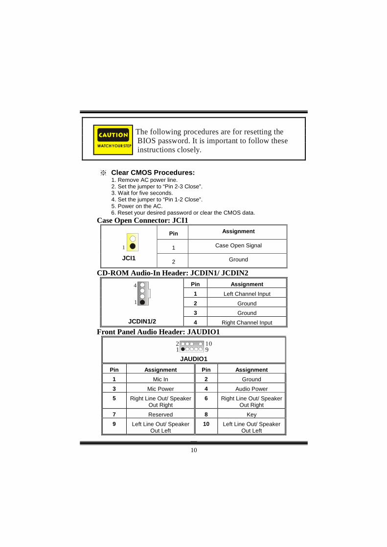
※ Clear CMOS Procedures: 1. Remove AC power line. 2. Set the jumper to “Pin 2-3 Close”. 3. Wait for five seconds. 4. Set the jumper to “Pin 1-2 Close”. 5. Power on the AC.
6. Reset your desired password or clear the CMOS data. Case Open Connector: JCI1
Pin Assignment Pin Assignment 1 Mic In 2 Ground 3 Mic Power 4 Audio Power 5 Right Line Out/ Speaker
Out Right 6 Right Line Out/ Speaker
Out Right 7 Reserved 8 Key 9 Left Line Out/ Speaker
Out Left 10 Left Line Out/ Speaker
Out Left
The following procedures are for resetting the BIOS password. It is important to follow these instructions closely.
11
Digital Audio Connector: JSPDIF1 Pin Assignment 1 +5V 2 SPDIF_OUT
3 1
JSPDIF1 3 Ground
Wake On LAN Header: JWOL1
Pin Assignment 1 +5V Standby 2 Ground
1 3
JWOL1
3 Wake up
Back Panel Connectors
PS/2Keyboard
PS/2Mouse
COM1
Parallel Port Game PortJPRNT1 JGAME1
JCOM1JKBMS1
USB
LAN(Optional)
JUSBLAN1
Speaker Out
Line In
Mic In
JVGA1
VGA1
12
Español Características del M6VLQ Pro
A. Hardware CPU
Proporciona Socket 370. Soporta procesador Celeron™ PPGA (FC-PGA & FC-PGA2) y Pentium® III Micro-Procesador (FC-PGA & FC-PGA2) y VIA C3 Ezra and Ezra –T Samuel 2 para estaciones de trabajo y servidores de alta capacidad. Front Side Bus a 66/100/133 MHz.
Chipset
North Bridge: VIA CLE266. South Bridge:VIA VT8235.
Memoria Principal Soporta hasta 2 dispositivos DDR. Soporta dispositivos DDR 200/266 MHz (sin ECC). Tamaño máxima de memoria 2GB.
Lan Chip (opcional)
Chip: VIA VT6103. Soporta 10 Mb/s y 100 Mb/s auto-negociación Half/ Full duplex.
Ranuras
Tres ranuras 32-bit PCI bus master. Una ranura CNR.
IDE Onboard
Soporta cuatro IDE disk drives. Soporta Modo PIO 4, Modo Bride y Ultra DMA 33/66/100/133 Modo Bus Master.
Super I/O
Chip: ITE IT8705. Proporciona el más alto funcionamiento de uso común para Super I/O. Environment Control initiatives - Monitor H/W - Controlador de Velocidad del Ventilador - Función ITE "Smart Guardian"
AC’97 Sound Codec Onboard
Chip: VIA VT1612A. AC’97 2.2 S/PDIF extensión del codec. 18-bit estéreo full duplex.
13
Periféricos Onboard a. Parte Trasera 1 puerto en serie. 1 puerto VGA. 1 puerto paralelo. (modos SPP/EPP/ECP) 1 puerto de audio en posición horizontal. 1 LAN jack. Ratón PS/2 y teclado PS/2. 2 puertos USB2.0. b. Parte Delantera 1 puerto para disquetera soportando 2 FDDs de 360K, 720K, 1.2M, 1.44M y
Ofrece el más alto funcionamiento para Windows 98 SE, Windows 2000, Windows Me, Windows XP, SCO UNIX etc.
Contenido del Paquete Cable HDD X1 Cable FDD X1 Manual del Usuario X1 Cable USB X1 (opcional) Panel trasero I/O para carcasa ATX X1 (opcional) Configuración completa del CD X1 Cable S/PDIF X1 (opcional) Aplicación del CD StudioFun! X1 (opcional)
14
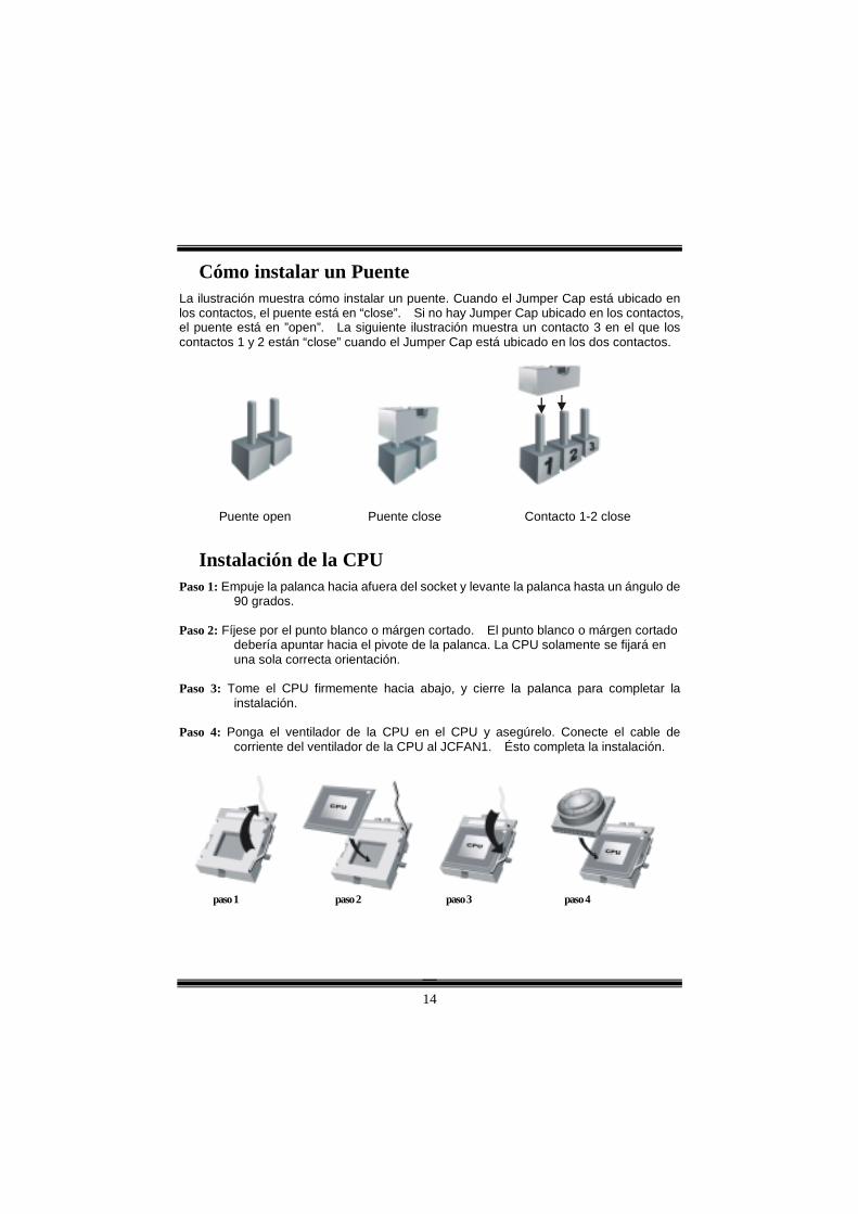
Cómo instalar un Puente La ilustración muestra cómo instalar un puente. Cuando el Jumper Cap está ubicado en los contactos, el puente está en “close”. Si no hay Jumper Cap ubicado en los contactos, el puente está en ”open”. La siguiente ilustración muestra un contacto 3 en el que los contactos 1 y 2 están “close” cuando el Jumper Cap está ubicado en los dos contactos.
Puente open Puente close Contacto 1-2 close
Instalación de la CPU Paso 1: Empuje la palanca hacia afuera del socket y levante la palanca hasta un ángulo de
90 grados. Paso 2: Fíjese por el punto blanco o márgen cortado. El punto blanco o márgen cortado
debería apuntar hacia el pivote de la palanca. La CPU solamente se fijará en una sola correcta orientación.
Paso 3: Tome el CPU firmemente hacia abajo, y cierre la palanca para completar la
instalación. Paso 4: Ponga el ventilador de la CPU en el CPU y asegúrelo. Conecte el cable de
corriente del ventilador de la CPU al JCFAN1. Ésto completa la instalación.
paso 1 paso 2 paso 3 paso 4
15
Cabezal del Sistema de Ventilación del CPU: JCFAN1 Conrtacto No. Asignación
1 Tierra 2 +12V 1
JCFAN1 3 FAN rpm Rate Sense
Cabezal del Sistema de Ventilación: JSFAN1
Contacto No. Asignación 1 Tierra 2 +12V
13
JSFAN1
3 FAN rpm Rate Sense
Módulos DIMM: DIMM1/ DIMM2 DRAM Tiempo de Acceso: 2.5V Unbuffered DDR 200/266 MHz Tipo requerido. DRAM Tipo: 64MB/ 128MB/ 256MB/ 512MB/ 1GB Módulo DIMM (184 contactos)
Total del Tamaño de Memoria Unbuffered DIMMs
Localización del Socket
DIMM
Módulo DDR Total del Tamaño de Memoria (MB)
DIMMB1 64MB/128MB/256MB/512MB/1GB *1
DIMMB2 64MB/128MB/256MB/512MB/1GB *1
Máximo 2GB
***Solamente para referencia***
Instalación del Módulo DDR 1. Abra una ranura de DIMM presionando el clip
de retención hacia afuera. Aliñe el DIMM en la ranura tales que la muesca en el DIMM encaje en la cumbrera de la ranura.
2. Inserte el DIMM verticalmente y firmemente en
la ranura hasta que el clip de retención vuelva a su posición original y el DIMM esté correctamente colocado.
16
Puentes, Cabezales, Conectores y Ranuras Conector de Disquetera: FDD1 La placa madre proporciona un conector estándar para disquete que soporta disquetera de 360K, 720K, 1.2M, 1.44M y 2.88M. Éste conector utiliza cables proporcionados por el disquete.
Conector del Disco Duro: IDE1/ IDE2 La placa madre tiene un controlador de 32-bit PCI IDE que proporciona Modo PIO 0~5, Bus Master, y funcionalidad Ultra DMA 33/ 66/ 100. Tiene dos conectores HDD: IDE1 (primario) y IDE2 (secundario). Los conectores IDE puede conectar a un disco master y uno esclavo, así puede conectar hasta cuatro discos duros. El primer disco duro debe estar siempre conectado al IDE1.
Ranuras de Interconexión del Componente Periférico: PCI1-3 Ésta placa madre está equipada con 3 ranuras estándar PCI. PCI es la sigla para Interconexión del Componente Periférico, y es un bus estándar para tarjetas de expansión. Ésta ranura PCI está diseñado con 32 bits.
Ranura de Banda de Suspensión de Comunicación y Red: CNR1 La especificación CNR es una abierta Industria de Arquitectura Estándar, que define una tarjeta de interface escalable del hardware en el que soporta solamente modem.
Conectores de Corriente: JATXPWR1 Contactos Asignación Contactos Asignación
1 +3.3V 11 +3.3V 2 +3.3V 12 -12V 3 Tierra 13 Tierra 4 +5V 14 PS_ON 5 Tierra 15 Tierra 6 +5V 16 Tierra 7 Tierra 17 Tierra 8 PW_OK 18 -5V 9 Voltaje Standby
8 Corriente LED (+)9 HDD LED (+) 10 Corriente LED (+)11 HDD LED (-)
LED del Disco Duro 12 Corriente LED (-)
Corriente LED
13 Tierra 14 Botón de Encendido
15 Control de Reinicio
Botón de Reinicio
16 Tierra
Botón de Encendido
17 NA 18 KEY 19 NA 20 KEY 21 +5V 22 Tierra 23 IRTX
Conector IrDA
24 IRRX
Conector IrDA
JPANEL1
18
Fuente de Corriente Selección para Teclado/ Ratón: JKBV1 JKBV1 Asignación Descripción
1
3
Contacto 1-2 close
+5V
+5V para teclado y ratón
1
3
Contacto 2-3 close
Voltaje Standby +5V
Ratón PS/2 y Teclado PS/2 son encendidos con un voltaje standby de
+5V
Nota: Para soportar la función “Encendiendo el sistema por medio del teclado y ratón”, el jumper cap del “JKBV1” debe ser ubicado en el contacto 2-3.
Fuente de Corriente Selección para USB: JUSBV1/ JUSBV2
JUSBV1/JUSBV2 Asignación Descripción
1 3 Contacto 1-2 close
+5V JUSBV1: 5V para conectores USB ubicados en el puerto JUSBLAN1
JUSBV2: 5V para conectores USB ubicado el el puerto JUSB1/2
1 3 Contacto 2-3 close
Voltaje Standby +5V
JUSBV1: puerto JUSBLAN1 encendidos con voltaje standby de 5V
JUSBV2: puertos JUSB1/2 encendidos con voltaje standby de 5V
Nota: Para soportar la función “Encendiendo el sistema por medio del dispositivo USB”, el jumper cap del “JUSBV1/ JUSBV2” debe ser ubicado en el contacto 2-3 respectivamente.
19
Puente de Borrar CMOS: JCMOS1
Los siguientes procesos son para reiniciar lacontrasena del BIOS. Es importante que siga loss i g u i e n t e s p a s o s c u i d a d o s a m e n t e .
~
※ Procedimientos para Borrar CMOS: 1. Quite el cable de corriente del AC. 2. Fijar el puente en el “contacto 2-3 close”. 3. Espere 5 segundos. 4. Fijar el Puente en el “contacto 1-2 close”. 5. Encienda AC.
6. Reconfigure la contraseña deseada o borre datos CMOS.
Conector de la Carcasa Abierta: JCI1 Contactos Asignación
1 Señal de la Carcasa Abierta 1 JCI1 2 Tierra
Cabezal de Entrada de Audio CD-ROM: JCDIN1/ JCDIN2 Contactos Asignación
1 Entrada del Canal Izquierdo 2 Tierra 3 Tierra
1
4
JCDIN1/2 4 Entrada del Canal Derecho
JCMOS1 Asignación
1
3
Contacto 1-2 Close
Operación Normal (default)
1
3
Contacto 2-3 Close
Borra datos del CMOS
20
Cabezal de Audio del Panel Frontal: JAUDIO1
12
910
JAUDIO1
Contactos Asignación Contactos Asignación 1 Entrada del Mic 2 Tierra 3 Corriente del Mic 4 Corriente de Audio 5 Salida de Línea Derecho/
Salida del Altavoz Derecho6 Salida de Línea Derecho/ Salida
del Altavoz Derecho 7 Reservado 8 Key 9 Salida de Línea Izquierdo/
Salida del Altavoz Izquierdo10 Salida de Línea Izquierdo/ Salida
del Altavoz Izquierdo
Conector Digital de Audio: JSPDIF1 Contactos Asignación
1 +5V 2 SPDIF_OUT
3 1
JSPDIF1 3 Tierra
Conectores del Panel Trasero
TecladoPS/2
RatonPS/2
COM1
Puerto Paralelo Puerto de JuegoJPRNT1 JGAME1
JCOM1JKBMS1
USB
LAN(Opcional)
JUSBLAN1
Salida delAltavoz
Entrada deLinea
Entrada del Mic
JVGA1
VGA1
21
StudioFun!TM Introduction
StudioFun!TM is a media-player based on optimized GNU/Linux distribution to bring a “Room Theater” experience into life. It plays DVD, VCD, MP3, Audio CD and other multimedia. Furthermore, Users can take snapshots of video and customize the saved images as screensavers or photo slideshows. Of course, the images can be stored in USB mass storage devices like flash disks and USB floppy disks.
Hardware Requirements The supported hardware list of StudioFun! updates regularly. So please check the “hwreq.txt” located in the root of StudioFun! Application Pack CD to get the latest supporting information.
Installation Procedure Insert the “StudioFun! Application Pack CD” in a CD/DVD ROM drive and let the system boot through the CD. The disk will boot and bring up the grub boot loader installation menu. Two options are specified: “StudioFun Install” and “StudioFun Recover”.
22
StudioFun! Install This option will do the basic installation of the distribution. The installation works on pre-installed windows or GNU/Linux distribution.
On selecting the “StudioFun Install” option the installer boots and displays a dialog box indicating the space required and waits for a confirmation. Selecting “Ok” will continue the installation while selecting “Cancel” will terminate the installation and reboot the machine.
If Windows or GNU/Linux is the only OS installed on the hard disk with no free space, it will resize the partition, either NTFS or FAT32 or ext2, and install StudioFun!. If the hard disk has a 128MB of free space available, the installation will use the free space.
After installing the base system you will be prompted to select the resolution from the following choices
1. 1024x768 (recommended)
2. 800x600
3. 640x480
Select the desired resolution. The default is 1024x768 for high-end graphics.
Next you will be prompted to choose the DVD area/region selection code. Choose this based on the type of DVDs you will be playing.
The installation procedure will then probe for the type of mouse installed. The distribution currently supports PS/2, USB and Serial mice. In case of serial mouse you will have to move the mouse when prompted. The other two are probed and installed automatically.
The installation procedure will now finish, the CD is ejected and a dialog box prompting to reboot the machine is displayed. Press “OK” button and enjoy StudioFun!.
3.1.1 Error Messages
1. Media corrupted!! Please check the media! The CD-ROM is corrupted.
2. Extraction of base system failed!! Please try again later!! The CD-ROM is corrupted.
3.Unsupported hardware found, Aborting... If you try to install StudioFun! on an unsupported and undocumented hardware the above error message is popped.
4. No device found! This error message is given if there is no hard disk in the system.
23
StudioFun! Recover Where there is a MBR (Master Boot record) corruption, the “StudioFun Recover” will automatically probe the hard disk master boot record and find out the installed operating system(s). Once success, it will re-install the boot loader with correct options in the MBR. Please be noted that the newly probed one will over write any custom boot loader option specified from other GNU/Linux installations.
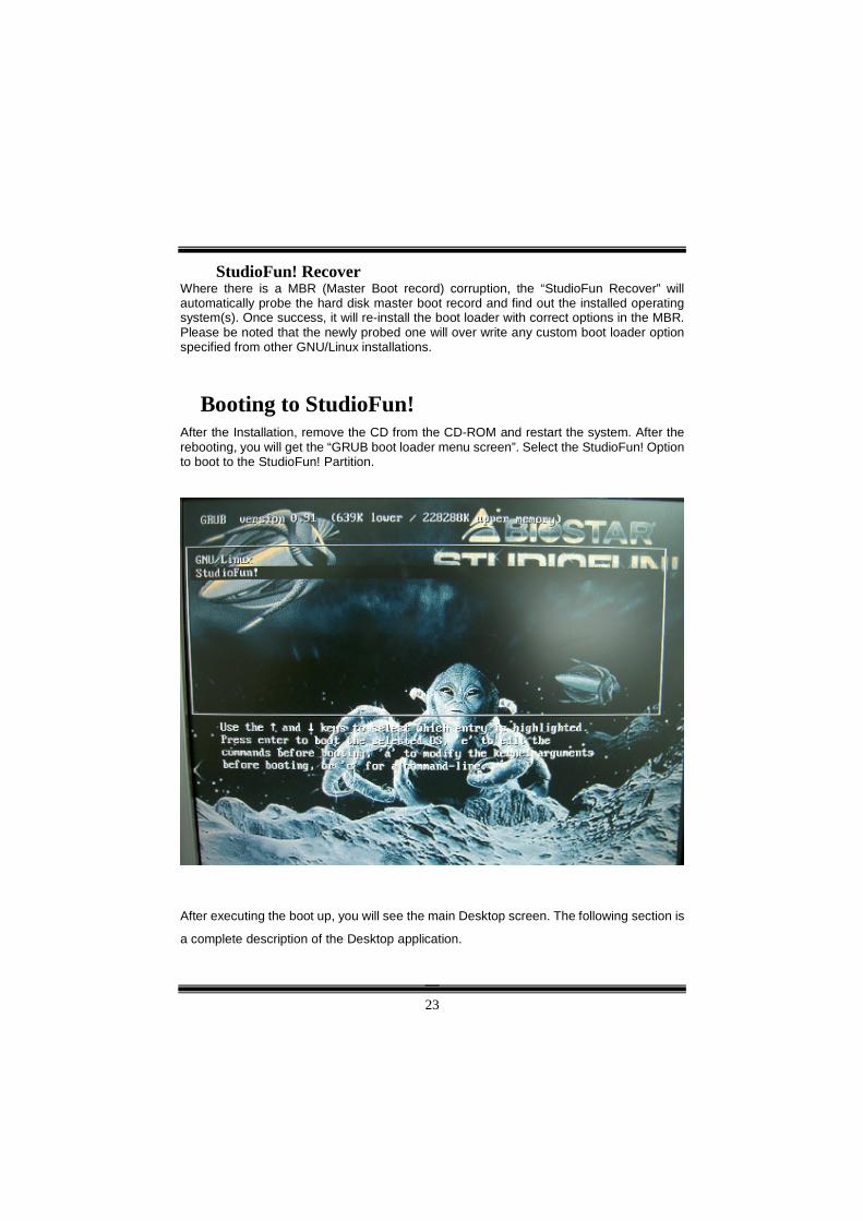
Booting to StudioFun! After the Installation, remove the CD from the CD-ROM and restart the system. After the rebooting, you will get the “GRUB boot loader menu screen”. Select the StudioFun! Option to boot to the StudioFun! Partition.
After executing the boot up, you will see the main Desktop screen. The following section is
a complete description of the Desktop application.
24
Desktop
This is the main shell of the StudioFun! software. It illustrates two main categories, one is the main "Media Control" part and the other is the "Control Panel".
Media control The Media Control consists of the following functionalities:
1. VCD This control icon will glow whenever a VCD is detected in a DVD/CD-ROM drive. The VCD will be auto-played only when it is put in to the drive when the Desktop (StudioFun! shell) is up and running whereas the control will simply glow to inform the user about a VCD present in the DVD/CD-ROM drive when the Desktop is not launched.
2. DVD This control will glow whenever a DVD is detected in a DVD drive. The DVD will be auto-played only when it is put in to the drive when the Desktop (StudioFun! shell) is up
25
and running, otherwise, the control will simply glow to inform the user about a DVD present in the DVD/CD-ROM.
3. MP3 This control will glow whenever a MP3 is detected in a DVD/CD-ROM drive. The MP3 will be auto-played only when it is put in to the drive when the Desktop (StudioFun! shell) is up and running, otherwise, the control will simply glow to inform the user about a MP3 present in the DVD/CD-ROM drive.
4. AUDIO This control will glow whenever a AUDIO is detected in a DVD/CD-ROM drive. The AUDIO will be auto-played only when it is put in to the drive when the Desktop (StudioFun! shell) is up and running, otherwise, the control will simply glow to inform the user about a AUDIO present in the DVD/CD-ROM drive.
5. FILE This control will glow whenever a File CD (CDs with other media type files) is detected in a DVD/CD-ROM drive. The File CD will be auto-played only when it is put in to the drive when the Desktop (StudioFun! shell) is up and running, otherwise, the control will simply glow to inform the user about a File CD present in the DVD/CD-ROM drive.
6. EJECT MEDIA When clicked this control, the file disk from the DVD/CDROM drives will be ejected.
7. EXIT This is the "Power on/off" control of the Desktop (StudioFun! shell).
Control Panel The Control panel part has five icons, which are shortcuts to other applications present in the StudioFun!. Tool tips will pop up once the mouse is rolled to the icons
1. Select Region Clicking this icon will invoke the application for selection DVD region settings. Refer to section 5.2 Select DVD Region application for more details.
2. Screensaver Clicking this icon will invoke the screensaver application. Refer to section 5.3 Screensaver for more details.
26
3. Display Settings Clicking this icon will invoke the application for changing the screen resolutions. Refer to section 5.4, Display Settings for more details.
4. File Manager Clicking this icon will invoke the file manager. Refer to section 5.6 File manager for more details.
When user has a DVD and a CD-ROM Drive, DVD Drive has the priority: If user has both DVD and a CD-ROM drive, DVD drive will be given the preference when both the drives hold valid media in them, i.e., if the CD-ROM drive has a media and a DVD drive also has a media, and the StudioFun! is started, the disk inside the DVD drive will be played.
Other general user scenarios When a user clicks on any of the media-controls when it is not glowing, except the eject media and exit, the media-player will just come up and wait for user input.
Software Details
XINE XINE is a multimedia player. It plays back Audio CD, DVD, and VCD. It also decodes multimedia files like AVI, MOV, WMV, and MP3 from local disk drives. It interprets most of the common multimedia formats.
27
• Features of Xine a. Skinnable GUI b. Navigation controls (seeking, pause, fast, slow, next
chapter, etc) c. On Screen Display (OSD) features d. DVD and external subtitles e. DVD/VCD menus (requires external plug-in) f. Audio and subtitle channel selection g. Closed Caption support h. Brightness, contrast, audio volume, hue, saturation
adjusting requires hardware/driver support) i. Playlist j. Image snapshot k. Audio re-sampling l. Software de-interlacing algorithms m. Configuration dialog n. Aspect ratio changing o. Full-screen display
• Supported File Formats
a. Video CD b. MPEG program streams (.mpg, .mpeg) c. ogg (.ogg) avi (.avi) d. asf (.asf, .wmv) e. QuickTime (.mov) f. MPEG-Video (.mpv, .m2v) g. MPEG-Audio (.mp2, .mp3) h. WAV (.wav) Video CODEC i. MPEG 1/2 j. MPEG 4 (aka OpenDivX) k. MS MPEG 4 a. Chapter 5: Software Details 10 l. Windows Media Video 7 m. Motion JPEG
28
• Remote Control Support. a. Infrared interface b. User-friendly
• Usage of StudioFun! with CelomaChrome skin a. Select VCD button to play a VCD disc b. Select DVD button to play a DVD disc c. Select CDDA button to play a Audio CD d. Select next chapter or MRL (>>|) button to play next track
in Audio CD, VCD and MP3 songs and to play next chapter in DVD
e. Select previous chapter or MRL (|<<) button to play previous track in Audio CD, VCD and MP3 songs and to play previous chapter in DVD
f. Select slow motion (<<) button to play the video / audio in slow motion (Select play button after reaching the required position)
g. Select fast motion (>>) button to play the video / audio in fast motion (Select play button after reaching the required position)
h. Select subs + / - button to select the appropriate subtitle (Usable while playing
i. Select audio + / - button to select the appropriate audio track (For example when
j. The DVD contains one audio track in English and the other with some other language,
k. Usable while playing DVD’s) l. Select “hide button” to hide the control panel of the player
m. Select “menu” button to use menu while playing DVD n. Select “control” button to adjust brightness / color o. Select “setup” button to modify the settings of the player p. Select ”f.scr” button to show the video output of the player
in full screen mode q. Select “snap” button to take a snapshot of the currently
playing video r. Select “plist” button to add / remove / manage playlist s. Select “mrl” button to add new file to play
29
Select Region Overview
Select region is a utility to set a DVD region. With the help of this application user can set or change a DVD region. Only one region can be set at a time.
About Select Region With the help of this application you can set a region for DVD. Only one region can be set at a time. If you keep the mouse pointer on any region, you can view the countries, which comes under that region. “Ok” - Click to set the selected region. “Cancel” - Click to quit the application.
How to select DVD region You can select only one region at a time. You can change your selection by clicking on any other region. • A snapshot of the application is shown below:
30
Screensaver Screensaver
The xscreensaver daemon waits until the keyboard and mouse have been idle for a period, and then runs a graphics demo chosen at random. The demo is terminated as soon as there is any mouse or keyboard activity. The xscreensaver-demo program is the graphical user interface to xscreensaver. It lets you tune the various parameters used by the xscreensaver daemon, and browse through the graphics demos. StudioFun! comes with xscreensaver when you click on the screensaver icon the application comes up. Then user can choose various graphics demos like chbg,halo,hypercube or hyperball.
Screensaver comes with various options • Preview Option: When a user selects a particular graphics demo and clicks on preview button the demo comes up. • Blank After Option: The screensaver will blank the screen after the keyboard and mouse have been idle default time is 1minute and user can change the settings. • Cycle After Option: When screensaver is running this cycle time defines the time limit for each screensaver. • Mode Screensaver comes with various modes: 1. Random Screen Saver: When user chooses this option, Screensaver cycles through various graphics demos randomly 2. Only one Screen Saver: When user chooses this option, screensaver displays only one graphics demo. 3. Blank Screen Only: When user chooses this option, screensaver only blanks the screen instead of displaying the graphics demo. 4. Disable Screen Saver: When user chooses this option, screensaver is disabled. • Various Graphics Demos XScreensaver comes with various screensaver Chbg: This screensaver displays the images stored in StudioFun! the time gap between images is 5 seconds. Hyperball Hypercube Halo Strange • A snapshot of the application is shown below:
31
Display Settings Display Settings
Display setting is a program to change the current resolution settings of the Display. By default user of StudioFun! will be given a choice to select between any of the following three resolutions. • 640x480 • 800x600 • 1024x768 The current resolution of the Display will be selected by default. It requires restart of the StudioFun! to reflect the changes made.
File Manager Overview
File manger is a utility to copy files from deferent devices to hard disk and vice versa. User can copy files from devices such as, floppy, CD-Rom and Flashdisk to hard disk and also
32
from hard disk to floppy and Flashdisk.
About File manager The hard disk files are stored in a directory called “/studiofun” on the hard disk. You can also delete files from hard disk, but you cannot delete files from any device. � Select device - Contains the device names /floppy, /cdrom and /flashdisk. Select a
device from/to which you want to copy files. Please double click the device option twice to mount the device.
� List Directories - Shows the list of directories of the selected device after double clicking it.
� Floppy/cdrom/Flashdisk - Shows the contents of the selected directory from the “List directories“ field after double clicking it.
� Hard disk - Shows the contents of a directory called “/studiofun”. � Add (>>) - Click to copy selected files from a device to hard disk. � Add (<<) - Click to copy selected files from hard disk to a device. � Remove - Click to delete files from hard disk. � Exit - Click to quit the application.
33
Watchdog Technology It is important to know that when overclocking, the system can be at a vulnerable state. Therefore, the BIOSTAR Watchdog Technology was designed to protect your PC under dangerous over-clock situations. Any over-clocking that reaches the threshold settings, the Watchdog Technology will disable your system from rebooting in the BIOS setting. Under this circumstance, please power off your PC. After that, press <Insert> and power on your system simultaneously to restart your system. This user-friendly design can save you from squandering your time on opening the case just to clear the CMOS. In the end, thanks to the Watchdog Technology, everything is back at a safe and sound!
34
WarpSpeeder
Introduction [ WarpSpeeder™ ], a new powerful control utility, features three user-friendly functions including Overclock Manager, Overvoltage Manager, and Hardware Monitor.
With the Overclock Manager, users can easily adjust the frequency they prefer or they can get the best CPU performance with just one click. The Overvoltage Manager, on the other hand, helps to power up CPU core voltage and Memory voltage. The cool Hardware Monitor smartly indicates the temperatures, voltage and CPU fan speed as well as the chipset information. Also, in the About panel, you can get detail descriptions about BIOS model and chipsets. In addition, the frequency status of CPU, memory, AGP and PCI along with the CPU speed are synchronically shown on our main panel.
Moreover, to protect users' computer systems if the setting is not appropriate when testing and results in system fail or hang, [ WarpSpeeder™ ] technology assures the system stability by automatically rebooting the computer and then restart to a speed that is either the original system speed or a suitable one.
System Requirement OS Support: Windows 98 SE, Windows Me, Windows 2000, Windows XP
DirectX: DirectX 8.1 or above. (The Windows XP operating system includes DirectX 8.1. If you use Windows XP, you do not need to install DirectX 8.1.)
35
Installation 1. Execute the setup execution file, and then the following dialog will pop up.
Please click “Next” button and follow the default procedure to install.
2. When you see the following dialog in setup procedure, it means setup is
completed. If the “Launch the WarpSpeeder Tray Utility” checkbox is checked, the Tray Icon utility and [WarpSpeeder™] utility will be automatically and immediately launched after you click “Finish” button.
36
Usage The following figures are just only for reference, the screen printed in this user manual will change according to your motherboard on hand.
[WarpSpeeder™] includes 1 tray icon and 5 panels:
1. Tray Icon:
Whenever the Tray Icon utility is launched, it will display a little tray icon on the right side of Windows Taskbar.
37
This utility is responsible for conveniently invoking [WarpSpeeder™] Utility. You can use the mouse by clicking the left button in order to invoke [WarpSpeeder™] directly from the little tray icon or you can right-click the little tray icon to pop up a popup menu as following figure. The “Launch Utility” item in the popup menu has the same function as mouse left-click on tray icon and “Exit” item will close Tray Icon utility if selected.
2. Main Panel
If you click the tray icon, [ WarpSpeeder™ ] utility will be invoked. Please refer
do the following figure; the utility’s first window you will see is Main Panel.
Main Panel contains features as follows: a. Display the CPU Speed, CPU external clock, Memory clock, AGP clock, and PCI clock information.
b. Contains About, Voltage, Overclock, and Hardware Monitor Buttons for invoking respective panels.
c. With a user-friendly Status Animation, it can represent 3 overclock percentage stages:
Duck walking => overclock percentage from 100% ~ 110 %
Duck running => overclock percentage from 110% ~ 120%
Duck burning => overclock percentage from 120% ~ above
38
3. Voltage Panel
Click the Voltage button in Main Panel, the button will be highlighted and the Voltage Panel will slide out to up as the following figure.
In this panel, you can decide to increase CPU core voltage and Memory voltage or not. The default setting is “No”. If you want to get the best performance of overclocking, we recommend you click the option “Yes”.
39
4. Overclock Panel
Click the Overclock button in Main Panel, the button will be highlighted and the Overclock Panel will slide out to left as the following figure.
40
Overclock Panel contains these features:
a. “–3MHz button”, “-1MHz button”, “+1MHz button”, and “+3MHz button”: provide user the ability to do real-time overclock adjustment.
Warning: Manually overclock is potentially dangerous, especially when the overclocking percentage is over 110 %. We strongly recommend you verify every speed you overclock by click the Verify button. Or, you can just click Auto overclock button and let [ WarpSpeeder™ ] automatically gets the best result for you. b. “Recovery Dialog button”: Pop up the following dialog. Let user select a restoring way if system need to do a fail-safe reboot.
41
c. “Auto-overclock button”: User can click this button and [ WarpSpeeder™ ] will set the best and stable performance and frequency automatically. [ WarpSpeeder™ ] utility will execute a series of testing until system fail. Then system will do fail-safe reboot by using Watchdog function. After reboot, the [ WarpSpeeder™ ] utility will restore to the hardware default setting or load the verified best and stable frequency according to the Recovery Dialog’s setting.
d. “Verify button”: User can click this button and [ WarpSpeeder™ ] will proceed a
testing for current frequency. If the testing is ok, then the current frequency will be saved into system registry. If the testing fail, system will do a fail-safe rebooting. After reboot, the [ WarpSpeeder™ ] utility will restore to the hardware default setting or load the verified best and stable frequency according to the Recovery Dialog’s setting.
Note: Because the testing programs, invoked in Auto-overclock and Verify, include DirectDraw, Direct3D and DirectShow tests, the DirectX 8.1 or newer runtime library is required. And please make sure your display card’s color depth is High color (16 bit) or True color( 24/32 bit ) that is required for Direct3D rendering.
42
5. Hardware Monitor Panel
Click the Hardware Monitor button in Main Panel, the button will be highlighted and the Hardware Monitor panel will slide out to left as the following figure.
In this panel, you can get the real-time status information of your system. The information will be refreshed every 1 second.
6. About Panel
Click the About button in Main Panel, the button will be highlighted and the About Panel will slide out to up as the following figure.
In this panel, you can get model name and detail information in hints of all the chipset that are related to overclocking. You can also get the mainboard’s BIOS model and the Version number of [ WarpSpeeder™ ] utility.
43
Note: Because the overclock, overvoltage, and hardware monitor features are controlled by several separate chipset, [ WarpSpeeder™ ] divide these features to separate panels. If one chipset is not on board, the correlative button in Main panel will be disabled, but will not interfere other panels’ functions. This property can make [ WarpSpeeder™ ] utility more robust.
44
Trouble Shooting PROBABLE SOLUTION
No power to the system at all Power light don’t illuminate, fan inside power supply does not turn on. Indicator light on keyboard does not turn on
* Make sure power cable is securely plugged in
* Replace cable
* Contact technical support
PROBABLE SOLUTION System inoperative. Keyboard lights are on, power indicator lights are lit, hard drive is spinning.
* Using even pressure on both ends of the DIMM, press down firmly until the module snaps into place.
PROBABLE SOLUTION System does not boot from hard disk drive, can be booted from CD-ROM drive.
* Check cable running from disk to disk controller board. Make sure both ends are securely plugged in; check the drive type in the standard CMOS setup.
* Backing up the hard drive is extremely important. All hard disks are capable of breaking down at any time.
PROBABLE SOLUTION System only boots from CD-ROM. Hard disk can be read and applications can be used but booting from hard disk is impossible.
* Back up data and applications files. Reformat the hard drive. Re-install applications and data using backup disks.
PROBABLE SOLUTION Screen message says “Invalid Configuration” or “CMOS Failure.”
* Review system’s equipment . Make sure correct information is in setup.
PROBABLE SOLUTION Cannot boot system after installing second hard drive.
* Set master/slave jumpers correctly.
* Run SETUP program and select correct drive types. Call drive manufacturers for compatibility with other drives.
Solución de Problemas CAUSA PROBABLE SOLUCIÓN
No hay corriente en el sistema. La luz de corriente no ilumina, ventilador dentro de la fuente de alimentación apagada. Indicador de luz del teclado apagado.
* Asegúrese que el cable de transmisión esté seguramente enchufado.
* Reemplace el cable.
* Contacte ayuda técnica.
CAUSA PROBABLE SOLUCIÓN Sistema inoperativo. Luz del teclado encendido, luz de indicador de corriente iluminado, disco rígido está girando.
* Presione los dos extremos del DIMM, presione para abajo firmemente hasta que el módulo encaje en el lugar.
CAUSA PROBABLE SOLUCIÓN Sistema no arranca desde el disco rígido, puede ser arrancado desde el CD-ROM drive.
* Controle el cable de ejecución desde el disco hasta el disco del controlador. Asegúrese de que ambos lados estén enchufados con seguridad; controle el tipo de disco en la configuración estándar CMOS.
* Copiando el disco rígido es extremadamente importante. Todos los discos rígidos son capaces de dañarse en cualquier momento.
CAUSA PROBABLE SOLUCIÓN Sistema solamente arranca desde el CD-ROM. Disco rígido puede leer y aplicaciones pueden ser usados pero el arranque desde el disco rígido es imposible.
* Copie datos y documentos de aplicación. Vuelva a formatear el disco rígido. Vuelva a instalar las aplicaciones y datos usando el disco de copiado.
CAUSA PROBABLE SOLUCIÓN Mensaje de pantalla ”Invalid Configuration” o “CMOS Failure.”
* Revise el equipo del sistema. Asegúrese de que la información configurada sea correcta.
CAUSA PROBABLE SOLUCIÓN No puede arrancar después de instalar el segundo disco rígido.
* Fije correctamente el puente master/esclavo.
* Ejecute el programa SETUP y seleccione el tipo de disco correcto. Llame a una manufacturación del disco para compatibilidad con otros discos.