CONFIDENTIAL AND PROPRIETARY : CKA RESOURCES LIMITED USE ONLY Atlas Geophysics Memorandum M2012010 Ooratippra Infill Gravity Survey CKA Resources Pty Ltd Memo completed by: Nathan Porter Database Manager/Processor T 08 6278 2898 F 08 6278 1595 PO BOX 1049 MORLEY WA 6943 AUSTRALIA [email protected]ABN 68 123 110 243 24 August 2012 Click to buy NOW! P D F - X C h a n g e V i e w e r w w w . d o c u - t ra c k . c o m Click to buy NOW! P D F - X C h a n g e V i e w e r w w w . d o c u - t ra c k . c o m
Transcript
CONFIDENTIAL AND PROPRIETARY : CKA RESOURCES LIMITED USE ONLY
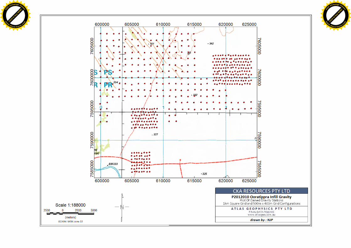
Project P2012010 “Ooratippra Infill” required the acquisition and processing of 514 gravity stations over tenements held by CKA Resources Pty Ltd. The gravity survey spanned an area covering approximately 25km by 22km, with the centre of the survey area located 20km north of the abandoned Ooratippra Homestead (Figure 1). Ooratippra Homestead is approximately 300km NE of the city of Alice Springs, Northern Territory. The survey area can be accessed via the Sandover Hwy.
Acquisition commenced on 2nd August 2012 and the survey was completed on the 3rd August 2012 with final data delivered shortly thereafter.
Gravity data were acquired using a 1km square grid configuration and a 500m x 400m grid configuration. Appendix B contains a plot of the locations of acquired gravity stations.
Atlas Geophysics completed the acquisition of the dataset using helicopter borne gravity methods. A single helicopter crew was used for the duration of the project.
The crew were self accommodated and messed at the Ooratippra Homestead.
The following instrumentation was used for acquisition of the gravity data:
One CG5 Autograv Gravity Meter (Serial Number 40241, SF 0.999283) Four Navcom SF3040 GPS-Glonass receivers
Ancillary equipment included:
Two HP Laptop computers for data download and processing Magellan FX324 autonomous GPS receivers for navigation Iridium satellite phones for long distance communications Personal Protective Equipment for all personnel Batteries, battery chargers, solar cells, UPS System Survey consumables Tools, engineering and maintenance equipment for vehicle servicing First aid and survival kits Tyres and recovery equipment GeoPro satellite tracking and communication system.
3.0 Calibration and Control
The gravity meter used for survey has been recently calibrated on the Guildford Cemetery – Helena Valley Primary School calibration range (2010990117- 2010990217) in Western Australia. The calibration process has validated the gravity meter’s scale factor to ensure reduction of the survey data produces correct Observed Gravities from measured dial reading values.
A single GPS-Gravity control station (GRVGPS0115 – Ooratippra) was previously established on 20th September 2010 to control field observations. Appendix A contains a description for the station.
Primary GPS control was established by submitting static data to Geoscience Australia’s AUSPOS processing system to produce first-order geodetic coordinates accurate to better than 10mm for the x, y and z observables. Multiple days of static GPS data have been submitted to verify accuracy and reliability of the solution. The details of the control process have been summarised in a table included in Appendix C.
Primary gravity control was established at the same location as the primary GPS control station. Once tied to the Australian Fundamental Gravity Network (AFGN), the gravity control station allowed all field gravity observations to be tied to the Australian Absolute Gravity Datum 2007 (AAGD07). An accurate observed or absolute gravity value for the control station was established via multiple “ABA” ties with the project gravity meter to AFGN station 1964919040 at Ammaroo Airstrip on 21st, 28th and 29th September 2010. Expected accuracy of the tie survey would be 0.01 mGal (0.1gu).
Gravity data were acquired concurrently with GPS data using a Scintrex CG5 gravity meter. Data were acquired in a single shift of 11 hours duration, with each shift consisting of a single loop controlled by observations at the gravity control station. Each loop contained a minimum of two repeated readings so that an interlocking network of closed loops was formed. A total of 2.92% repeats were acquired for quality control purposes. Repeat readings were evenly distributed on a time-basis throughout each of the gravity loops.
GPS data were acquired with the rover receivers operating in post-process kinematic (PPK) mode, with one rover receiver mounted to the front of the helicopter (fixed antenna height of 0.860m) and the second rover receiver mounted to the tail boom of the helicopter (fixed height of 1.870m).
Static data were logged at the control station for submission to AUSPOS for verification of final coordinates.
5.0 GPS Processing and QA
The acquired GPS and Glonass raw data were processed nightly in the field using Novatel Waypoint GrafNav v8.4 post-processing software. The resulting data (in Atlas Geophysics PPK standard format) were then imported into Atlas Geophysics Reduction and Interpretation Software (AGRIS) for QA and use in the reduction of the gravity data.
Projection from GPS-Glonass derived WGS84/GDA94 coordinates to Map Grid of Australia (MGA) coordinates was performed in GrafNav. For most practical applications where a horizontal accuracy of only a metre or greater is required, GDA94 coordinates can be considered the same as WGS84. MGA coordinates were obtained by projecting the GPS-derived WGS84 coordinates onto MGA Zone 53S using a Universal Transverse Mercator (UTM) projection. Elevations above the Australian Height Datum (AHD) were modelled using GrafNav software and the AUSGEOID09 geoid model.
A module built into AGRIS allowed the user to import the positional data from GrafNav and examine quality factors such as station repeatability between multiple control stations, coordinate velocity, dilution of precision, coordinate quality factor and standard error for each gravity station location. The procedure is carried out before merging the positional data with gravity data for final reduction to Bouguer anomaly. Comprehensive statistics, repeatability analysis and histogram plotting are also performed.
Quality control procedures were applied to the GPS-Glonass data on a daily basis and any gravity stations not conforming to the quoted specifications were repeated by the company at no cost to the client.
The acquired gravity data were processed using the company’s in-house gravity pre-processing and reduction software, AGRIS. This software allows for full data pre-processing, reduction to Bouguer Anomaly, repeatability and statistical analysis, as well as full quality analysis of the output dataset.
Once downloaded from the gravity meter, the data are analysed for consistency and preliminary QA is performed to check that observations meet specification for standard deviation, reading rejection, temperature and tilt values. Once the data are verified, the software averages the multiple readings and performs a merge with the GPS data (which it has also previously verified) and performs a linear drift correction and earth tide correction. Any gravity stations not conforming to the quoted specifications were repeated by the company at no cost to the client.
The following corrections were applied to the dataset to produce Spherical Cap Bouguer Anomalies on the GRS80 ellipsoid and AAGD07 gravity datum. For legacy reasons, Geoidal Bouguer Anomalies on the Australian Height Datum (AHD) and ISOGAL84 gravity datum have also been calculated. The formulae below produce data in µms-2 or gravity units. To convert to mGal, divide by a factor of 10.
Instrument scale factor: This correction is used to correct a gravity reading (in dial units) to a relative gravity unit value based on the meter calibration. = 10 ∙ ( ∙ ( )) where,
corrected reading in gravity units gravity meter reading in dial units ( ) scale factor (dial units/milliGal)
Earth Tide Correction: The earth is subject to variations in gravity due to the gravitational attraction of the Sun and the Moon. These background variations can be corrected for using a predictive formula which utilises the gravity observation position and time of observation. The Scintrex CG5 gravity meter automatically calculates ETC but uses only an approximate position for the gravity observation so is not entirely accurate. For this reason, the Scintrex ETC is subtracted from the reading and a new correction calculated within AGRIS software. = +
where, tide corrected reading in gravity units scale factor corrected reading in gravity units
Earth Tide Correction (ETC) in gravity units
Instrument Drift Correction: Since all gravity meters are mechanical they are all prone to instrument drift. Drift can be caused by mechanical stresses and strains in the spring mechanism as the meter is moved, knocked, reset, subjected to temperature extremes,
subjected to vibration, unclamped etc. The most common cause of instrument drift is due to extension of the sensor spring with changes in temperature (obeying Hooke’s law). To calculate and correct for daily instrument drift, the difference between the gravity control station readings (closure error) is used to assume the drift and a linear correction is applied.
= −−
where, Instrument Drift in gu/hour control station 2nd reading in gravity units control station 1st reading in gravity units control station 2 time control station 1 time
Observed Gravity: The preceding corrections are applied to the raw gravity reading to calculate the earth’s absolute gravitational attraction at each gravity station. The corrections produced Observed Gravities on the AAGD07 and ISOGAL84 datums. = + ( − ) − ( − ) ∙
where, Observed Gravity in gravity units (ISOGAL84 or AAGD07)
control station 1 known Observed Gravity in gravity units tide corrected reading in gravity units
control station 1 reading in gravity units reading time
control station 1 time instrument drift in gravity units/hour
Theoretical Gravity 1980: The theoretical (or normal) gravity value at each gravity station is calculated based on the assumption that the Earth is a homogeneous ellipsoid. The closed form of the 1980 International Gravity Formula is used to approximate the theoretical gravity at each station location and essentially produce a latitude correction. Gravity values vary with latitude as the earth is not a perfect sphere and the polar radius is much smaller than the equatorial radius. The effect of centrifugal acceleration is also different at the poles versus the equator. = 9780326.7715((1 + 0.001931851353( )/( (1 − 0.0066943800229( ))) where,
Theoretical Gravity 1980 in gravity units GDA94 latitude at the gravity station in decimal degrees
Theoretical Gravity 1967: The theoretical (or normal) gravity value at each gravity station is calculated based on the assumption that the Earth is a homogeneous ellipsoid. The 1967 variant of the International Gravity Formula is used to approximate the theoretical gravity at each station location and essentially produce a latitude correction. Gravity values vary with latitude as the earth is not a perfect sphere and the polar radius is much smaller than the
equatorial radius. The effect of centrifugal acceleration is also different at the poles versus the equator. = (9780318.456 ∙ 1 + 0.005278895 ∙ ( ) + 0.000023462 ∙ ( ) ) where,
Theoretical Gravity 1967 in gravity units GDA94 latitude at the gravity station in decimal degrees
Atmospheric Correction: The gravity effect of the atmosphere above the ellipsoid can be calculated with an atmospheric model and is subtracted from the theoretical gravity. = 8.74– 0.00099 ∙ ℎ + 0.0000000356 ∙ ℎ
where, Atmospheric Correction in gravity units ℎ elevation above the GRS80 ellipsoid in metres
Ellipsoidal Free Air Correction: Since the gravity field varies inversely with the square of distance, it is necessary to correct for elevation changes from the reference ellipsoid (GRS80). Gravitational attraction decreases as the elevation above the reference ellipsoid increases. = −(3.087691– 0.004398 ² ) ∙ ℎ + 7.2125 ∙ 10 ∙ ℎ
where, Ellipsoidal Free Air Correction in gravity units
GDA94 latitude at the gravity station in decimal degrees ℎ elevation above the GRS80 ellipsoid in metres
Geoidal Free Air Correction: Since the gravity field varies inversely with the square of distance, it is necessary to correct for elevation changes from the reference geoid (AHD). Gravitational attraction decreases as the elevation above the reference geoid increases. = 3.08768 − 0.00440 ( ) ∙ ℎ − 0.000001442 ∙ ℎ
where, Free Air Correction in gravity units
GDA94 latitude at the gravity station in decimal degrees ℎ elevation above the reference geoid (AHD) in metres
Spherical Cap Bouguer Correction: If a gravity observation is made above the reference ellipsoid, the effect of rock material between the observation and the ellipsoid must be taken into account. The mass of rock makes a positive contribution to the gravity value. The correction is calculated using the closed form equation for the gravity effect of a spherical cap of radius 166.7km, based on a spherical Earth with a mean radius of 6,371.0087714km, height relative the ellipsoid and rock densities of 2.67, 2.40 and 2.20 tm-3 (gm/cc). = 2πGρ((1 + μ) ∙ ℎ– λR)
where, Spherical Cap Bouguer Correction in gravity units
gravitational constant = 6.67428∙10-11m3kg-1s-2 ρ rock density (2.67, 2.40 and 2.20 tm-3) ℎ elevation above the GRS80 ellipsoid in metres R ( + ℎ) the radius of the earth at the station mean radius of the earth = 6,371.0087714 km (on the GRS80 ellipsoid) & are dimensionless coefficients defined by: = ((1/3) ∙ η − η)
2 ∙ [ ( /2) − ( /2)] / with S = Bullard B Surface radius = 166.735 km
Geoidal Bouguer Correction: If a gravity observation is made above the reference geoid, the effect of rock material between the observation and the ellipsoid must be taken into account. The mass of rock makes a positive contribution to the gravity value. The slab of rock makes a positive contribution to the gravity value. Rock densities of 2.67, 2.40 and 2.20 t/m-3 (gm/cc) were used in the correction. = 0.4191 ∙ ρ ∙ ℎ
where, Geoidal Bouguer Correction in gravity units ρ rock density (2.67, 2.40 and 2.20 tm-3) ℎ elevation above the reference geoid (AHD) in m
Terrain Correction: The terrain correction accounts for variations in gravity values caused by variations in topography near the observation point. The correction accounts for the attraction of material above the assumed Bouguer slab and for the over-correction made by the Bouguer correction when in valleys. The terrain correction is positive regardless of whether the local topography consists of a mountain or a valley. Terrain corrections were not applied on this project as the survey area was flat and devoid of any appreciable topography.
Ellipsoidal Free Air Anomaly: The Ellipsoidal Free Air Anomaly is the difference between the observed gravity and theoretical gravity that has been computed for latitude and corrected for the elevation of the gravity station above or below the reference ellipsoid.
= – ( − ) −
where, Ellipsoidal Free Air Anomaly in gravity units Observed Gravity on the AAGD07 datum in gravity units
Theoretical Gravity 1980 in gravity units Atmospheric Correction in gravity units
Ellipsoidal Free Air Correction in gravity units
Geoidal Free Air Anomaly: The Geoidal Free Air Anomaly is the difference between the observed gravity and theoretical gravity that has been computed for latitude and corrected for the elevation of the gravity station above or below the reference geoid.
= − +
where, Free Air Anomaly in gravity units Observed Gravity on the ISOGAL84 datum in gravity units Theoretical Gravity 1967 in gravity units Geoidal Free Air Correction in gravity units
Spherical Cap Bouguer Anomaly: The Spherical Cap Bouguer Anomaly is computed from the Ellipsoidal Free Air Anomaly above by removing the attraction of the spherical cap calculated by the Spherical Cap Bouguer Correction.
= −
where, Spherical Cap Bouguer Anomaly in gravity units Ellipsoidal Free Air Anomaly in gravity units Bouguer Correction in gravity units
Geoidal Bouguer Anomaly: The Geoidal Bouguer Anomaly is computed from the Geoidal Free Air Anomaly above by removing the attraction of the slab calculated by the Geoidal Bouguer Correction.
= −
where, Geoidal Bouguer Anomaly in gravity units
Geoidal Free Air Anomaly in gravity units Geoidal Bouguer Correction in gravity units
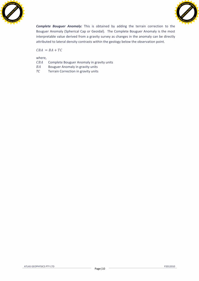
Complete Bouguer Anomaly: This is obtained by adding the terrain correction to the Bouguer Anomaly (Spherical Cap or Geoidal). The Complete Bouguer Anomaly is the most interpretable value derived from a gravity survey as changes in the anomaly can be directly attributed to lateral density contrasts within the geology below the observation point.
= +
where, Complete Bouguer Anomaly in gravity units
Bouguer Anomaly in gravity units TC Terrain Correction in gravity units
The gravity survey was completed with two days of acquisition. An average acquisition rate of 257 stations per day of production was achieved over the duration of the project. A copy of the full production report is contained on the data DVD.
Final raw data have met and exceeded quoted project specifications. Repeatability of the data was good, with the standard deviation of the elevation repeats at 0.053m and the standard deviation of the gravity repeats at 0.025 mGal. The production report contains summary statistics and histograms for repeatability.
8.0 Data Formats and Deliverables
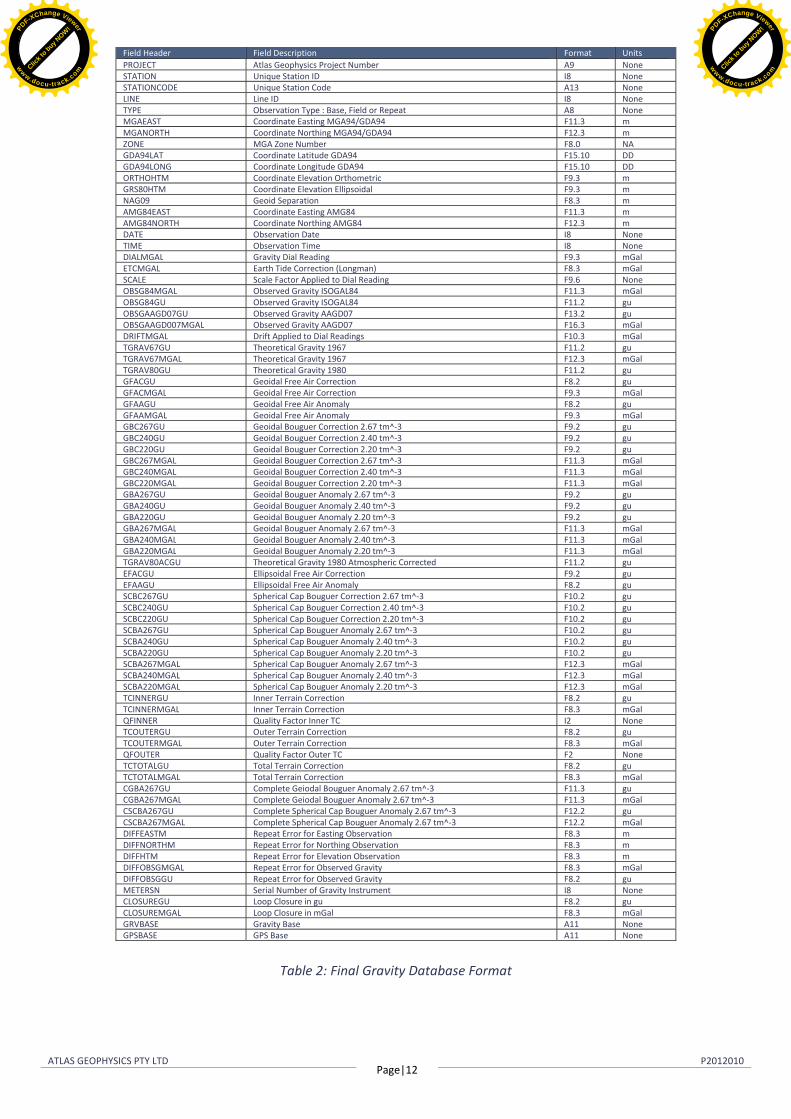
Final reduced ASCII data for the project have been delivered in standard Atlas format. Table 2 overleaf details the format of the final gravity database supplied. All fields are comma delimited.
Appendix B contains plots of final station locations, images of GPS Derived Elevation (GRS80), Spherical Cap Bouguer Anomaly and first vertical derivative of Spherical Cap Bouguer Anomaly.
Raw GPS-GNSS and gravity data in their respective native formats have been included on the data DVD as Appendix D. Table 1 below summarises the deliverables.
Final Delivered Data Format Data DVD Hardcopy
Gravity Database Comma Space Delimited .csv •
Gravity Database Geosoft Database .gdb •
Gravity Database Point located data ASEG-GDF2 •
Raw Positional Data AGRIS format, comma delimited •
Prior to survey commencement, a Hazard Identification and Risk Assessment (HIRA) was carried out for all new tasks not covered under Atlas Geophysics Standard Operating Procedures (SOP’s) or the company’s Health Safety Environment (HSE) field manual.
Weekly toolbox meetings were held to discuss project safety and address any staff member concerns. The entire survey was conducted safely, with no incidents to report for the project.
OBSERVED GRAVITY Date established: 19/09/2012 gu AAGD07 9786886.47
mGal ISOGAL84 978688.725
Occupation Method/Location Details At this control station, the GPS control point consists of a steel picket driven into the ground with approximately 15cm protruding. The gravity control point consists of a small concrete slab set into the ground, opposite the GPS control point. The control station is witnessed by an Atlas Geophysics survey plaque (reading GRVGPS0115) attached to a 1.5 metre steel picket placed within 0.5m of the both control points.
Gravity Control was established via multiple ABA loops with the project meter to AFGN 1964919040 at Ammaroo Station on 21st, 28th and 29th September 2010. Expected accuracy would be better than 0.01 mGal.
GPS Control was established using AUSPOS. Three separate 10 hour sessions were submitted to AUSPOS’s online processing systems where returned coordinates were accurate to better than 0.01m.
The station is located approximately 7.9 km south of the Sandover Highway at Ooratippra Homestead. The station is located approximately 25m from the old shearing quarters and workshop along an old and white poled fence. Also located 15m from the base is a Telstra phone box.
Photograph of Control Station GRVGPS0115 and surrounds