7
M Pact Air Circuit Breaker 400-4000A New
| Date post: | 19-Feb-2018 |
| Category: |
Documents |
| Upload: | dejanoskia |
| View: | 229 times |
| Download: | 0 times |
7/23/2019 M Pact MPro Air CircuitBreakers
http://slidepdf.com/reader/full/m-pact-mpro-air-circuitbreakers 1/6
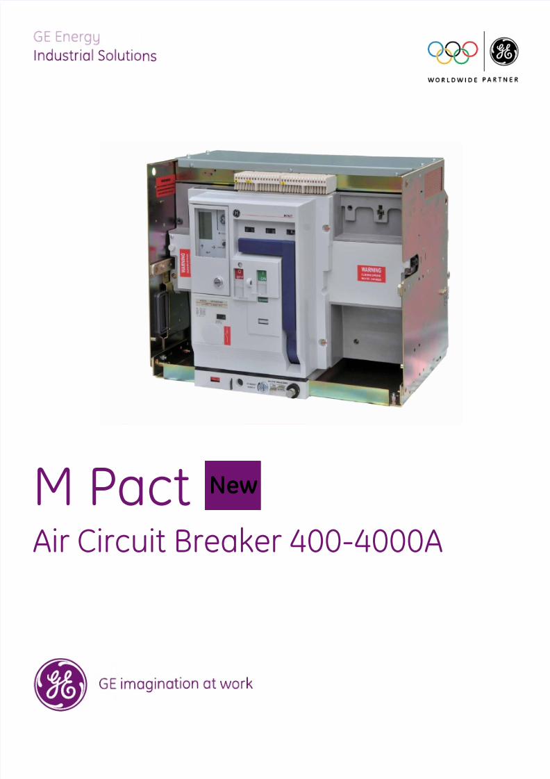
M Pact
Air Circuit Breaker 400-4000A
New

7/23/2019 M Pact MPro Air CircuitBreakers
http://slidepdf.com/reader/full/m-pact-mpro-air-circuitbreakers 2/6
Specication
Approvals
Rated from 400 to 4000A the M Pact circuit breakerhas been designed to meet the most stringent demandsin fault detection and safe interruption thereof.
Available in 2 frame sizes:- frame size 1 ranging from 400 to 2500A- frame size 2 ranging from 800 to 4000A
The range has been developed to be aesthetically
and technically co-ordinated with other protectivedevices within the GE Power Controls industrialproduct ranges.
The breaker range has a common height and depth andis available in both xed pattern and drawout versionswhich can be manually or electrically operated.
Designed to oer multiple mains connection options, italso comes with a wide range of easy-to-install accessories.
M Pact Air Circuit Breakers comply with the followingspecications for Low Voltage Switchgear:• IEC 60947-1• IEC 60947-2• IEC 60947-3• Utilisation category B
KEMA certication in accordance with IEC 60947-2CCC certication in accordance with GB14048-2CCS certication in accordance with China Certication of shipping
3 performance ranges*A -50 kA (Icu)D -65 kA (Icu)
H1, H2 -80 kA (Icu)*Ratings shown at 415V AC2 compact frame sizesFrame size 1 - 400 to 2500AFrame size 2 - 800 to 4000AFixed and withdrawable versions3 or 4 pole congurationFront and rear access connections (horizontal/vertical)Devices provided with or without protection relayManual or electrical operation
Common height and depth dimensionsBuilt-in safety features e.g. safety shuttersWide range of protection settings oering full selectivityCombinations of earth fault protectionEasy-to-install accessories, common to entire range
Simple and ecient servicing on site
Type A Type D Type H1,H2
2
7/23/2019 M Pact MPro Air CircuitBreakers
http://slidepdf.com/reader/full/m-pact-mpro-air-circuitbreakers 3/6
Characteristics
Design and specications are subject to changes without notice.
Selectivity
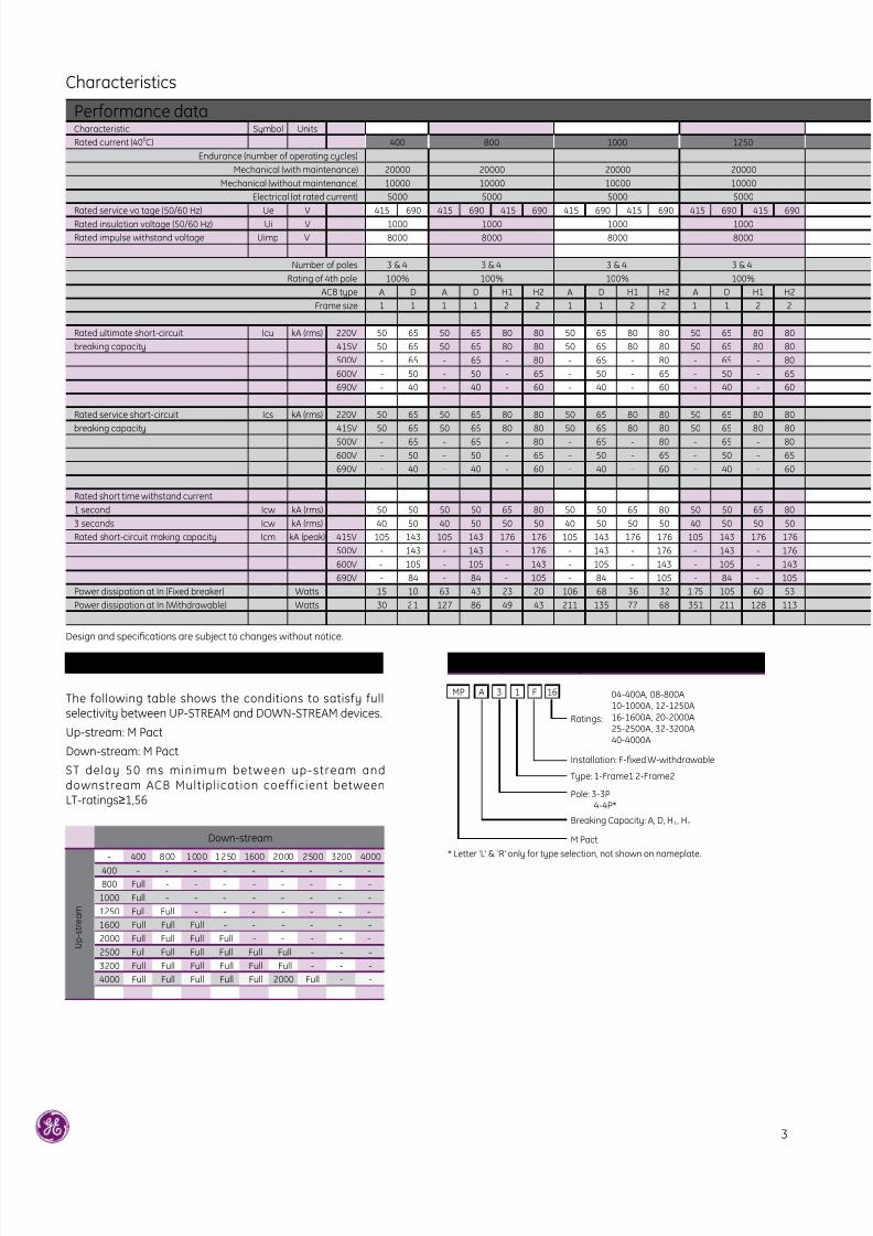
The following table shows the conditions to satisfy fullselectivity between UP-STREAM and DOWN-STREAM devices.
Up-stream: M Pact
Down-stream: M Pact
ST delay 50 ms minimum between up-stream anddownstream ACB Multipl ication coefficient betweenLT-ratings≥1,56
Down-stream
- 400 800 1000 1250 1600 2000 2500 3200 4000
400 - - - - - - - - -
800 Full - - - - - - - -
1000 Full - - - - - - - -
1250 Full Full - - - - - - -
1600 Full Full Full - - - - - -
2000 Full Full Full Full - - - - -
2500 Full Full Full Full Full Full - - -
3200 Full Full Full Full Full Full - - -
4000 Full Full Full Full Full 2000 Full - -
U p - s t r e a m
Catalog No. conguration
MP A 3 1 F 16
Ratings:
04-400A, 08-800A10-1000A, 12-1250A16-1600A, 20-2000A25-2500A, 32-3200A40-4000A
Installation: F-xed W-withdrawable
Type: 1-Frame1 2-Frame2
* Letter 'L' & 'R' only for type selection, not shown on nameplate.
Breaking Capacity: A, D, H1, H2
M Pact
Pole: 3-3P 4-4P*
Performance dataCharacteristic Symbol Units
Rated current (400C) 400 800 1000 1250
Endurance (number of operating cycles)
Mechanical (with maintenance) 20000 20000 20000 20000
Mechanical (without maintenance) 10000 10000 10000 10000
Electrical (at rated current) 5000 5000 5000 5000
Rated service voltage (50/60 Hz) Ue V 415 690 415 690 415 690 415 690 415 690 415 690 415 690
Rated insulation voltage (50/60 Hz) Ui V 1000 1000 1000 1000
Rated impulse withstand voltage Uimp V 8000 8000 8000 8000
Number of poles 3 & 4 3 & 4 3 & 4 3 & 4
Rating of 4th pole 100% 100% 100% 100%
ACB type A D A D H1 H2 A D H1 H2 A D H1 H2
Frame size 1 1 1 1 2 2 1 1 2 2 1 1 2 2
Rated ultimate short-circuit Icu kA (rms) 220V 50 65 50 65 80 80 50 65 80 80 50 65 80 80
breaking capacity 415V 50 65 50 65 80 80 50 65 80 80 50 65 80 80
500V - 65 - 65 - 80 - 65 - 80 - 65 - 80
600V - 50 - 50 - 65 - 50 - 65 - 50 - 65
690V - 40 - 40 - 60 - 40 - 60 - 40 - 60
Rated service short-circuit Ics kA (rms) 220V 50 65 50 65 80 80 50 65 80 80 50 65 80 80
breaking capacity 415V 50 65 50 65 80 80 50 65 80 80 50 65 80 80500V - 65 - 65 - 80 - 65 - 80 - 65 - 80
600V - 50 - 50 - 65 - 50 - 65 - 50 - 65
690V - 40 - 40 - 60 - 40 - 60 - 40 - 60
Rated short time withstand current
1 second Icw kA (rms) 50 50 50 50 65 80 50 50 65 80 50 50 65 80
3 seconds Icw kA (rms) 40 50 40 50 50 50 40 50 50 50 40 50 50 50
Rated short-circuit making capacity Icm kA (peak) 415V 105 143 105 143 176 176 105 143 176 176 105 143 176 176
500V - 143 - 143 - 176 - 143 - 176 - 143 - 176
600V - 105 - 105 - 143 - 105 - 143 - 105 - 143
690V - 84 - 84 - 105 - 84 - 105 - 84 - 105
Power dissipation at In (Fixed breaker) Watts 15 10 63 43 23 20 106 68 36 32 1 75 105 60 53
Power dissipation at In (Withdrawable) Watts 30 21 127 86 49 43 211 135 77 68 351 211 128 113
3
7/23/2019 M Pact MPro Air CircuitBreakers
http://slidepdf.com/reader/full/m-pact-mpro-air-circuitbreakers 4/6
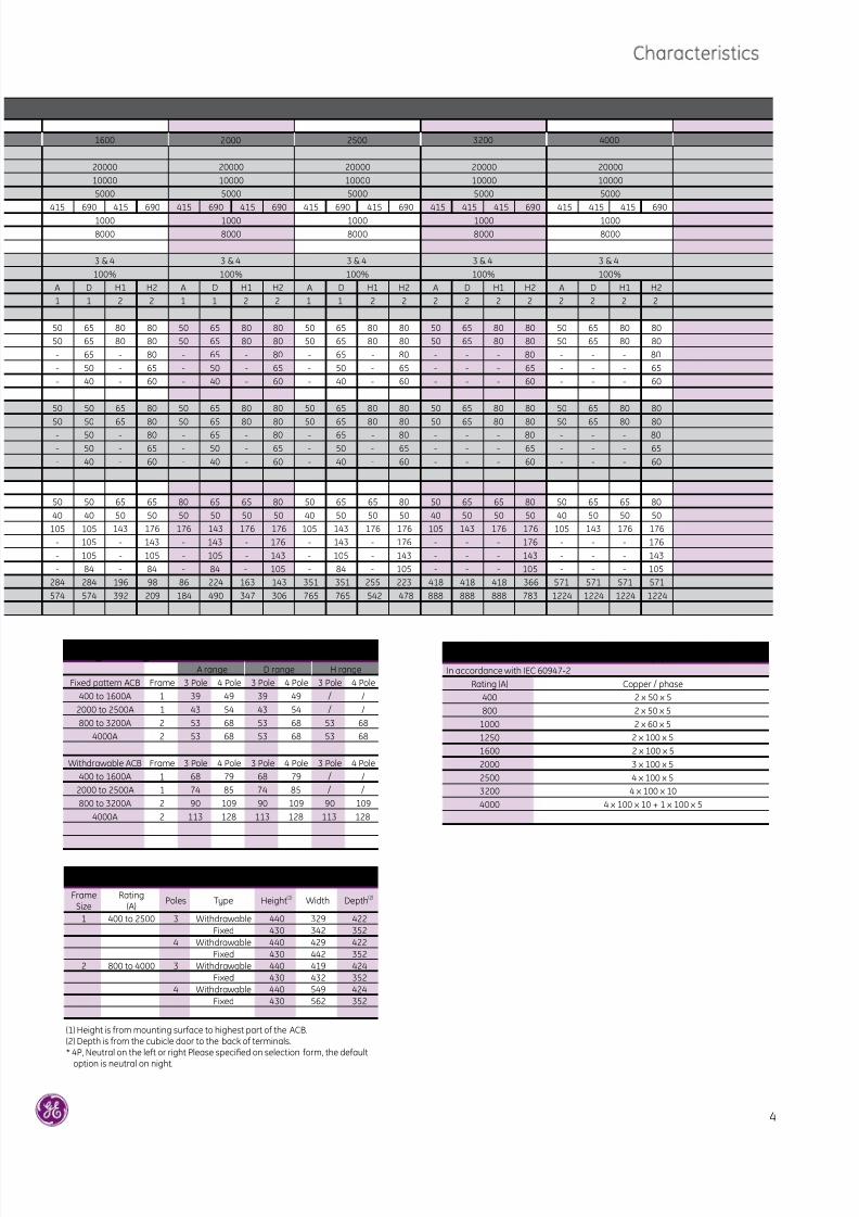
Weights (kg)A range D range H range
Fixed pattern ACB Frame 3 Pole 4 Pole 3 Pole 4 Pole 3 Pole 4 Pole
400 to 1600A 1 39 49 39 49 / /
2000 to 2500A 1 43 54 43 54 / /
800 to 3200A 2 53 68 53 68 53 68
4000A 2 53 68 53 68 53 68
Withdrawable ACB Frame 3 Pole 4 Pole 3 Pole 4 Pole 3 Pole 4 Pole
400 to 1600A 1 68 79 68 79 / /
2000 to 2500A 1 74 85 74 85 / /
800 to 3200A 2 90 109 90 109 90 109
4000A 2 113 128 113 128 113 128
Recommended minimum copper sizeIn accordance with IEC 60947-2
Rating (A) Copper / phase
400 2 x 50 x 5
800 2 x 50 x 5
1000 2 x 60 x 5
1250 2 x 100 x 5
1600 2 x 100 x 5
2000 3 x 100 x 5
2500 4 x 100 x 5
3200 4 x 100 x 10
4000 4 x 100 x 10 + 1 x 100 x 5
Dimensions in mmFrame
SizeRating
(A) Poles Type Height(1) Width Depth(2)
1 400 to 2500 3 Withdrawable 440 329 422Fixed 430 342 352
4 Withdrawable 440 429 422Fixed 430 442 352
2 800 to 4000 3 Withdrawable 440 419 424Fixed 430 432 352
4 Withdrawable 440 549 424Fixed 430 562 352
(1) Height is from mounting surface to highest part of the ACB.(2) Depth is from the cubicle door to the back of terminals.* 4P, Neutral on the left or right Please specied on selection form, the default
option is neutral on night.
1600 2000 2500 3200 4000
20000 20000 20000 20000 20000
10000 10000 10000 10000 10000
5000 5000 5000 5000 5000
415 690 415 690 415 690 415 690 415 690 415 690 415 415 415 690 415 415 415 690
1000 1000 1000 1000 1000
8000 8000 8000 8000 8000
3 & 4 3 & 4 3 & 4 3 & 4 3 & 4
100% 100% 100% 100% 100%
A D H1 H2 A D H1 H2 A D H1 H2 A D H1 H2 A D H1 H2
1 1 2 2 1 1 2 2 1 1 2 2 2 2 2 2 2 2 2 2
50 65 80 80 50 65 80 80 50 65 80 80 50 65 80 80 50 65 80 80
50 65 80 80 50 65 80 80 50 65 80 80 50 65 80 80 50 65 80 80
- 65 - 80 - 65 - 80 - 65 - 80 - - - 80 - - - 80
- 50 - 65 - 50 - 65 - 50 - 65 - - - 65 - - - 65
- 40 - 60 - 40 - 60 - 40 - 60 - - - 60 - - - 60
50 50 65 80 50 65 80 80 50 65 80 80 50 65 80 80 50 65 80 80
50 50 65 80 50 65 80 80 50 65 80 80 50 65 80 80 50 65 80 80- 50 - 80 - 65 - 80 - 65 - 80 - - - 80 - - - 80
- 50 - 65 - 50 - 65 - 50 - 65 - - - 65 - - - 65
- 40 - 60 - 40 - 60 - 40 - 60 - - - 60 - - - 60
50 50 65 65 80 65 65 80 50 65 65 80 50 65 65 80 50 65 65 80
40 40 50 50 50 50 50 50 40 50 50 50 40 50 50 50 40 50 50 50
105 105 143 176 176 143 176 176 105 143 176 176 105 143 176 176 105 143 176 176
- 105 - 143 - 143 - 176 - 143 - 176 - - - 176 - - - 176
- 105 - 105 - 105 - 143 - 105 - 143 - - - 143 - - - 143
- 84 - 84 - 84 - 105 - 84 - 105 - - - 105 - - - 105
284 284 196 98 86 224 163 143 351 351 255 223 418 418 418 366 571 571 571 571
574 574 392 209 184 490 347 306 765 765 542 478 888 888 888 783 1224 1224 1224 1224
4
7/23/2019 M Pact MPro Air CircuitBreakers
http://slidepdf.com/reader/full/m-pact-mpro-air-circuitbreakers 5/6
5
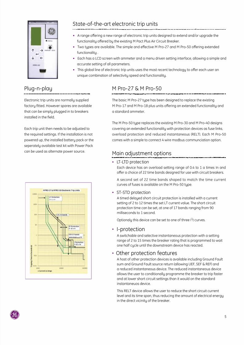
State-of-the-art electronic trip units
Plug-n-play M Pro-27 & M Pro-50
Main adjustment options
• A range oering a new range of electronic trip units designed to extend and/or upgrade the
functionality oered by the existing M Pact Plus Air Circuit Breaker.
• Two types are available. The simple and eective M Pro-27 and M Pro-50 oering extended
functionality .
• Each has a LCD screen with ammeter and a menu driven setting interface, allowing a simple and
accurate setting of all parameters.
• This global line of electronic trip units uses the most recent technology to oer each user an
unique combination of selectivity speed and functionality.
Electronic trip units are normally supplied
factory tted. However spares are available
that can be simply plugged in to breakers
installed in the eld.
Each trip unit then needs to be adjusted to
the required settings. If the installation is not
powered up, the installed battery pack or the
seperately available test kit with Power Pack
can be used as alternate power source.
The basic M Pro-27 type has been designed to replace the existing
M Pro-17 and M Pro-18 plus units oering an extended functionality and
a standard ammeter.
The M Pro-50 type replaces the existing M Pro-30 and M Pro-40 designs
covering an extended functionality with protection devices as fuse links,
overload protection and reduced instantaneous (RELT). Each M Pro-50
comes with a simple to connect 4 wire modbus communciation option.
• LT-LTD protection
• ST-STD protection
• I-protection
• Other protection features
Each device has an overload setting range of 0.4 to 1 a times In and
oer a choice of 22 time bands designed for use with circuit breakers.
A second set of 22 time bands shaped to match the time currentcurves of fuses is available on the M Pro-50 type.
A timed delayed short circuit protection is installed with a current
setting of 2 to 12 times the set LT current value. The short circuit
protection time can be set, at one of 17 bands ranging from 90
milliseconds to 1 second.
Optionaly this device can be set to one of three I2t curves.
A switchable and selective instantaneous protection with a setting
range of 2 to 15 times the breaker rating that is programmed to waitone half cycle until the downstream device has reacted.
A host of other protection devices is available including Ground Fault
sum and Ground Fault source return (allowing UEF, SEF & REF) and
a reduced instantaneous device. The reduced instantaneous device
allows the user to conditionally programme the breaker to trip faster
and at lower short circuit settings than it would on the standard
instantaneuos device.
This RELT device allows the user to reduce the short circuit current
level and its time span, thus reducing the amount of electrical energy
in the direct vicinity of the breaker.
7/23/2019 M Pact MPro Air CircuitBreakers
http://slidepdf.com/reader/full/m-pact-mpro-air-circuitbreakers 6/6
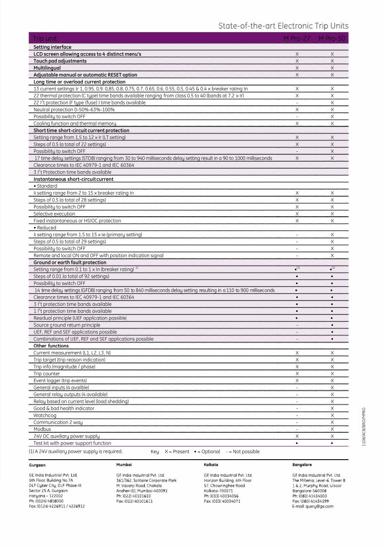
Trip unit M Pro-27 M Pro-50Setting interface
LCD screen allowing access to 4 distinct menu's X X
Touch pad adjustments X X
Multilingual X X
Adjustable manual or automatic RESET option X X
Long time or overload current protection
13 current settings Ir 1, 0.95, 0.9. 0,85, 0.8, 0.75, 0.7, 0.65, 0.6, 0.55, 0.5, 0.45 & 0.4 x breaker rating In X X
22 thermal protection (C type) time bands available ranging from class 0.5 to 40 (bands at 7.2 x Ir) X X22 I2t protection (F type {fuse} ) time bands available - X
Neutral protection 0-50%-63%-100% X X
Possibility to switch OFF - X
Cooling function and thermal memory X X
Short time short-circuit current protection
Setting range from 1.5 to 12 x Ir (LT setting) X X
Steps of 0.5 (a total of 22 settings) X X
Possibility to switch OFF - X
17 time delay settings (STDB) ranging from 30 to 940 milliseconds delay setting result in a 90 to 1000 milliseconds X X
Clearance times to IEC 40979-1 and IEC 60364
3 I2t Protection time bands available
Instantaneous short-circuit current
• Standard
Ii setting range from 2 to 15 x breaker rating In X XSteps of 0.5 (a total of 28 settings) X X
Possibility to switch OFF X X
Selective execution X X
Fixed instantaneous or HSIOC protection X X
• Reduced
Ii setting range from 1.5 to 15 x Ie (primary setting) - X
Steps of 0.5 (a total of 29 settings) - X
Possibility to switch OFF - X
Remote and local ON and OFF with position indication signal - X
Ground or earth fault protection
Setting range from 0.1 to 1 x In (breaker rating) (1) •(1) •(1)
Steps of 0.01 (a total of 92 settings) • •
Possibility to switch OFF • •
14 time delay settings (GFDB) ranging from 50 to 840 milliseconds delay setting resulting in a 110 to 900 milliseconds • •
Clearance times to IEC 40979-1 and IEC 60364 • •
3 I2t protection time bands available • •
1 I4t protection time bands available • •
Residual principle (UEF application possible) • •
Source ground return principle - •
UEF, REF and SEF applications possible - •
Combinations of UEF, REF and SEF applications possible - •
Other functions
Current measurement (L1, L2, L3, N) X X
Trip target (trip reason indication) X X
Trip info (magnitude / phase) X X
Trip counter X X
Event logger (trip events) X X
General inputs (4 availble) - X
General relay outputs (4 available) - X
Relay based on current level (load shedding) - X
Good & bad health indicator - X
Watchdog - X
Communication 2 way - X
Modbus - X
24V DC auxiliary power supply X X
Test kit with power support function • •
(1) A 24V auxiliary power supply is required. Key X = Present • = Optional - = Not possible
1 1 0 8 / A C B / B R O / M P R O


