67
M Series 14-18t Internal Combustion Counterbalanced Forklift truck Operation and Maintenance Manual Zhejiang Maximal Forklift Co., Ltd

M Series 14-18t Internal Combustion
Counterbalanced Forklift truck
Operation and Maintenance Manual
Zhejiang Maximal Forklift Co., Ltd

M Series 14-18t Internal Combustion Counterbalanced Forklift truck Operation and Maintenance Manual
I
FOREWORD
This manual mainly introduces the performance, structure, operation and
maintenance and other contents of FD140-180T forklift truck, in order that users or
operators are able to use and maintain it properly.
While users are in the use process, relevant operators and equipment
management personnel should conscientiously implement the relevant requirements
and regulations of this manual for use and maintenance, to make the forklift often
keep good state of use.
If any operation or maintenance doesn’t accord with requires in this manual, our
related promises is inefficacy, please pay attention.
Because of continuous improvement in parts and devices, the content of the
manual will change, without prior notice, please users understand.

M Series 14-18t Internal Combustion Counterbalanced Forklift truck Operation and Maintenance Manual
II
Contents
I.Safety rules for Operation and Daily Maintenance of Forklift Truck ................. - 1 -
Ⅱ. Primary Parameter of Forklift Truck................................................................. - 13 -
Ⅲ. Primary Assembly of Forklift Truck ................................................................. - 15 -
IV. The structure, principle, adjustment and maintenance of forklift ..................... - 16 -
1. Dynamic system .................................................................................................. - 16 -
2. Transmission device ............................................................................................ - 17 -
3. Drive axle ............................................................................................................ - 24 -
4. Steering system ................................................................................................... - 27 -
5. Steering Axle ....................................................................................................... - 33 -
6. Brake System ...................................................................................................... - 36 -
7. Electric system .................................................................................................... - 40 -
8. Hydraulic System ................................................................................................ - 48 -
9. Hoist system ........................................................................................................ - 58 -

M Series 14-18t Internal Combustion Counterbalanced Forklift truck Operation and Maintenance Manual
- 1 -
I.Safety rules for Operation and Daily Maintenance of Forklift Truck
It is important that driver and manager for forklift trucks remember the principle
of the “first safety” and ensure the safety operation and standard operation as the
description in OPERATION AND SERVICE MANUAL.
1. Delivery of Forklift Truck
It must be pay attention to the following items when you deliver forklift trucks:
(1) Apply the parking brake.
(2) Fix the mast and the balance weight with steel wire. Wedge up all wheels.
(3) Sling points should be always at the positions specified in sling index plate
when hoisting up the forklift truck.
2. Storage of Forklift Truck
(1) Drain off fuel completely.
(2) Apply antirust to the surface of the parts not painted. Apply lubrication oil to
the lift chain.
(3) Descend the mast to the lowest position.
(4) Apply the parking brake.
(5) Wedged up the front and rear tyre.
3. Precaution Before Operation
(1) Don’t check fuel leakage and lever or instruments at the place where there is
open flame. Never fill the fuel tank with the engine running.
(2) Check the tire inflation pressure.
(3) The forward-reverse lever should be in neutral.
(4) Never smoke while the fuel system is under working or the battery is
inspected.
(5) Check all the levers and pedals.
(6) Complete the provisions before starting.
(7) Release the parking brake.
(8) Make trying operation of the mast for lifting, descend and Fwd/Bwd tilting
and the truck for steering and braking.
(9) The contamination level of the hydraulic oil should be lower than 12.

M Series 14-18t Internal Combustion Counterbalanced Forklift truck Operation and Maintenance Manual
- 2 -
4. Safety operation rules of Forklift Truck
Sound power level of this truck is equal or less than 106dB. Sound pressure level
of cab is equal or less than 80dB. On condition that no-load truck is running at the
maximum speed, the integrated vibration acceleration of person on the seat is equal or
less than 5.8 m/s2. For sake of safety and efficiency, driver must observe the following
instructions:
(1) Only trained and driving license authorized operator shall be permitted to
operate the truck.
(2) Wear all the safety guards, such as shoes, helmet, clothing and gloves while
operating the truck.
(3) The truck is forbidden to be used in explosive environment stacked with LPG
bottle, timber, paper and chemicals.
(4) Check all the control and warning devices before starting the truck. If any
damages or defects are found, operate it after repairing.
(5) At the rated loading center, either overload or overload operation is strictly
prohibited. If the cargo is placed at non-rated loading center, the capacity is decided
according to load curve graph. The center of cargo should be in line with the frame
center, not but of the line. The fork should insert completely under the cargo and make
the cargo placed on it evenly. Do not raise an object with single fork.
(6) The starting, turning, driving, braking and stopping operation of the truck
should be done smoothly. When steering on the humid or low friction road, the truck
should be decelerated.
(7) Travel with loads as low as possible and tilted the mast backward.
(8) Be careful when traveling on a slope. When the climbing grades with a slope
of more than 10%, the truck should forward travel, and when descend so grades,
backward travel. Never turning on a slope. Avoid loading and unloading operation
when descending.
(9) Pay attention to pedestrian, obstacle and bumpy road when driving. Pay
attention to the clearance over forklift truck.
(10) Never allow any persons to stand on/under the forks. Never permit anyone

M Series 14-18t Internal Combustion Counterbalanced Forklift truck Operation and Maintenance Manual
- 3 -
to walk under upraised forks or the truck to carry persons.
(11) Don’t operate truck and attachment of it at any position out of the drive seat.
(12) Don't handle the stacked goods unsecured or loose, and handle the goods in
large size carefully.
(13) On the high forklift truck, when the lift height more than 3m, it is noted that
the goods on it should not fall down or the protection measures must be taken if
necessary.
(14) Tilt the mast of the high lift forklift truck as backward as possible while the
truck working. Use minimum for forward tilt angle and min. reverse tilt when loading
and unloading.
(15) Be careful and slowly driving over a dock board or temporary bed plank.
(16) Shut down the engine and don’t stay on the truck when filling fuel. Don’t
ignite the engine while checking battery or fuel lever.
(17) The unloaded forklift truck with attachments should be operated as a loaded
truck.
(18) If leaving the truck, lower the forks on the ground and let the shift lever to
neutral, shut down the engine or cut down electric supply. If parking on the slope, the
parking brake device is connected, and the wheels need to be padded with wedge
when parking for a long time.
(19) Don’t open the radiator cap when the engine is very hot
(20) The pressure of the multi-way valve and relief valve has been adjusted
before the fork starts, and users do not adjust in the process of using, so as to avoid
excessive pressure damaging the whole hydraulic system and hydraulic components
(21) During loading and unloading operations, adjustment of parts, overhauling
or maintenance is strictly forbidden.
(22) It is strictly forbidden the fork in the running process turns at a high speed.
(23) Tyres are inflated according to the pressure value regulated on the “tyre air
pressure” sign.
(24) When mast leans forward, cargo lifting and driving lifting with fork are
strictly forbidden.

M Series 14-18t Internal Combustion Counterbalanced Forklift truck Operation and Maintenance Manual
- 4 -
5. Points for attention on use of cooling system
(1) The cooling medium used for the radiator of the forklift of our company is
generally long-lasting antirust and antifreeze liquid (FD-2 type-35℃), which is not
changed around the year, regardless of summer or winter. Generally, after being used
for one year, it should be let out for filtration and purification and then put to use
again. The cooling system, is furnished with an auxiliary water tank, on the wall of
which are marked with “FULL” and ”LOW”, between which the level of antifreeze
liquid should stay when the system is in use.
(2) Regularly check the sealing performance of the cooling system and the level
of cooling liquid and shoot the trouble as early as possible, otherwise, the auxiliary
water tank will lose its function, give wrong indication of level and finally shorten the
lifetime of the engine.
(3) When antifreeze liquid is used as cooling medium, it is strictly forbidden to
add water and different type of antifreeze liquid at will. Antifreeze liquid of same type
should be replenished after the liquid leaks or evaporates.
(4) If water is used as cooling medium, it probably freezes in cold winter when
the machine is at the time of parking. In this case, the water should be discharged
from the radiator. After the radiator works for a period of time, it should be
dismantled and put into boiling soda solution for cleaning the scale or sediment
accumulated on the inner surface of it.
(5) During operation, if the radiator of forklift “boils” or the temperature of
cooling liquid is too high, do not open the cover of radiator immediately. If the cover
needs to be removed to find out the cause for it, reduce the rotational speed of engine
to the moderate, slowly rotate the cover and not remove it very soon so as to prevent
operators from being scalded by the splashing liquid.
When the radiator cap is tightened, it must be tightened in place; otherwise the
system is not sealed, which is difficult to establish the provided system pressure.
(6) Based on different working conditions, regularly clean the outer surface of
the radiator with detergent, or wash it with compressed air or high-pressure water (no
less than 4kg/cm2).

M Series 14-18t Internal Combustion Counterbalanced Forklift truck Operation and Maintenance Manual
- 5 -
6. Anti-tilting Safety Attention

M Series 14-18t Internal Combustion Counterbalanced Forklift truck Operation and Maintenance Manual
- 6 -
7. Packaging and Transport
Lifting Forklift Truck
• The lifting holes at both ends of outer upright mounting beam are fastened with the
counterweight hook by the wire rope, and then the forklift truck will be lifted by using
lifting equipment.
Warning:
• When lifting the forklift truck, be sure not to wind the wire rope and the overhead
guard together.
• The wire rope and lifting device shall be very strong to safely support the forklift
truck (forklift truck is extremely heavy.)
• Do not use the cab (overhead guard) to lift the forklift truck.
• When lifting forklift truck, do not enter the forklift truck bottom.
Handling:
• The forklift truck is generally used for loading and unloading and short-distance
transport and not suitable for long-distance transport. If the forklift truck is used for

M Series 14-18t Internal Combustion Counterbalanced Forklift truck Operation and Maintenance Manual
- 7 -
long-distance transport, the ship, train, or more than 25T load-carrying automobile
and other load-carrying vehicles are needed for handling. The wheel is padded with a
wedge, and the vehicle body is tied securely to prevent slippage of vehicle in transit.
8. Nameplate & warning label
Usage and precaution on the label are for the sake of you and truck. Please
operate the truck conforming to instructions. If the label drops please replace it with a
new one.
(1) Nameplate
(1) Fork lift nameplate

M Series 14-18t Internal Combustion Counterbalanced Forklift truck Operation and Maintenance Manual
- 8 -
(2) Safety label
Standing on or under the fork is prohibited, in
case personal security is threatened by rising or
falling of the fork.
(3) No standing behind the mast please.
Standing behind the mast is forbidden against
potential safety hazard.
(4) For goods only!
Warning: Carriage of person is forbidden.
Warning
Forbid Hitching People

M Series 14-18t Internal Combustion Counterbalanced Forklift truck Operation and Maintenance Manual
- 9 -
(5) Tyre safety label
Warning: it needs to be aware of when installing and
inflating the tyres.
(6) No hoisting!
Lifting with the two holes is prohibited to prevent confusion
with the two holes below for hoisting.
(7) Caution! The rolling fan!
The label warns of potential hazard to be caught and
hurt by the fan.
(8) Caution! Hot!
Warning: High temperature hidden trouble exists
in exhaust pipes, in order to prevent hands being
scalded.
(9) Antifreeze added already.
The label warns that antifreeze has been added
already.
War
ing

M Series 14-18t Internal Combustion Counterbalanced Forklift truck Operation and Maintenance Manual
- 10 -
(10) Caution! The clamping mast!
The label warns of potential danger during the
rising and falling of mast, in case that the moving
mast clamps hand.
(11) Alert to tipping over please.
The label warns of potential danger rising out of
tipping over.
(12) Danger! Electricity!
The label warns of potential danger of electric shock.
(13) No flushing.
No flushing for fear of water penetration into air
filter.

M Series 14-18t Internal Combustion Counterbalanced Forklift truck Operation and Maintenance Manual
- 11 -
10. Oil Used for Forklift Truck
Name Brand Code (Homeland) Brand Code (Export)
Fuel (Diesel) No.0 in summer;
No.-10 in winter
Lubricant for Gear GL-5 85W/90
Hydraulic Oil L-HM32
Hydraulic Drive Oil SG/CF-4 15W-40
Brake Oil GL-5 85W/90
Lubricant for Engine SG/CF-4 15W-40
Grease No.3 Lithium Base Grease
(drop point 170)

M Series 14-18t Internal Combustion Counterbalanced Forklift truck Operation and Maintenance Manual
- 12 -
11. The Chart of Lubrication System
Inspection every 1200 hours
Inspection every 600 hours
Inspection every 200 hours
Inspection every 8 hours
Steering cylinder
Wheel bearing
Steering center pin
Tilting cylinder pin
Braking fluid
Wheel bearing
Mast bracket lid
Radiator
Crankcase
Oil tank
Torcon oil
(hydraulic type)
Transmission
(machanic type)
Differential
Mast Tilter cylinder pin
Free lift plate
Lifting chain
Oil types
Brake oil
Torcon oil
Exchange Supply Water
Engine oil
Gear lubricant
Lubricant
Wheel bearing Lubricant Operating tank oil

M Series 14-18t Internal Combustion Counterbalanced Forklift truck Operation and Maintenance Manual
- 13 -
Ⅱ. Primary Parameter of Forklift Truck
Technical parameter table for
FD140 (160,180)T-MWK 14-18T diesel hydraulic forklift
No. Parameter name Unit FD140T FD160T FD180T
1 Rated lifting capacity kg 14000 16000 18000
2 Load centre distance mm 1220 1220 1220
3 Lift height mm 4000 4000 4000
4 Mast tilt angle Deg 6°/12° 6°/12° 6°/12°
5 Lifting speed
(Full load/No load) mm/sec 350/380 350/380 350/380
6 Max.Travelling speed
(No load) km/h 30 30 30
7 Max.Gradeability (With load)) % 25 25 25
8 Max.Drawbar pull (With load) kN 125 125 125
9 Wheel base mm 3800 3800 3800
10 Tread
Front mm 1850 1850 1850
11 Rear mm 2120 2120 2120
12 Overhang
Front mm 1060 1060 1060
13 Rear mm 1000 1000 1000
14 Fork
dimension L×W×T mm
2440×250×100 2440×250×105 2440×250×110
15 Lateral fork adjustment
(Outside of fork) mm
810-2140 810-2140 810-2140
16 Min.ground clearance
(Bottom of mast) mm 230 230 230
17 Min.turning radius (Outside) mm 5100 5100 5100
18
Shape
dimensions
Length mm 8300 8300 8300
19 Width mm 2535 2535 2535
20 Height
(Mast) mm 3915 3915 3915
21
Engine
Model Cummins
QSB6.7
Cummins
QSB6.7
Cummins
QSB6.7
22 Rated
output/rpm. kW 142/2300 142/2300 142/2300
23 Rated
torque/rpm. N·m 930/1500 930/1500 930/1500
24 Cylinder No. 6 6 6
25 Diameter×
Distance mm 107×124 107×124 107×124

M Series 14-18t Internal Combustion Counterbalanced Forklift truck Operation and Maintenance Manual
- 14 -
26 Displacement L 6.7 6.7 6.7
27
Transmission
Model ZF3WG171 ZF3WG171 ZF3WG171
28 Stage
(FWD/RVS) 3/3 3/3 3/3
29
Tire
Driving wheel 4 12.00-24-20PR 12.00-24-20PR 12.00-24-20PR
30 Steering
wheel 2 12.00-20-20PR 12.00-20-20PR 12.00-20-20PR
31 Gravity (including oily water) kg 24300 25300 26000

M Series 14-18t Internal Combustion Counterbalanced Forklift truck Operation and Maintenance Manual
- 15 -
Ⅲ. Primary Assembly of Forklift Truck
No. Name Contents
1 Engine mounting Includes engine, air cleaner
2 Cooling System Mainly including the radiator, water pipe and auxiliary water tank
3 Exhaust System Mainly including muffler, exhaust hose and telescopic hose
4 Oil Cooling System
of torque converter Mainly including torque converter oil radiator and cooling oil pipe
5 Transmission
System
Mainly including transmission assembly, torque converter, drive
shaft assembly and variable speed control
6 Drive axle assembly Includes axle house, half shafts, differential, hub reduction,
wet-type brake
7 Brake System Mainly including brake valve, parking brake valve, brake oil
pump, filling valve, brake tube and accumulator
8 Steering Axle
Mainly including steering axle, steering king pin, steering knuckle
assembly, wheel hub, connecting rod assembly and steering
cylinder
9 Steering System Mainly including full hydraulic steering gear and redirector
10 Wheel Includes front tyre, & rim, rear tyre & rim
11 Frame System Includes frame, tank in frame, hood, floor, counterweight, seat
12 Lifting system Includes outer & inner mast, lift bracket, cylinder positioner, fork,
lift cylinder, end roller, side roller, sheave, chain
13 Tilting Cylinder Includes cylinder body, piston assembly, cylinder cover, oil seal
14 Hydraulic System Includes control valve, oil pump, oil filter, cover plate
15 Electric System Includes air-conditions, combination meter, lamp, battery

M Series 14-18t Internal Combustion Counterbalanced Forklift truck Operation and Maintenance Manual
- 16 -
IV. The structure, principle, adjustment and maintenance of forklift
1. Dynamic system
(1) Introduction
The dynamic system includes the installation of the engine, air inlet system,
cooling system and exhaust system, etc. The engine is linked to transmission device.
The holder of engine is connected with the frame of the forklift through a rubber
cushion to reduce vibration. The power of engine is transferred to the driving system
by a flywheel through a torque converter.
The power of forklift FD140-180 is provided by diesel engine Cummins QSB6.7
imported from USA. The accessories of the engine such as air filter and silencer are
all from the supplier of Cummins equipments to ensure normal operation and
maintenances for the engine. Operation and maintenance of the engine refer to the
Engine Operation and Maintenance Manual
(2) Primary Parameter of Cummins QSB6.7 Engine
Parameter Cummins QSB6.7
Type Four-stroke, increase Pressure and Mid-cooling
in-line
Cylinders No.-Bore× Stroke 6-107×124
Total output 6.7 L
Compression Ratio 16.5
Rated Power / Speed 142 kW / 2300rpm
Rated Torque / Speed 930N·m/1500rpm
Idle Speed 800rpm
Min. Fuel Consume 213 g / kW·h
Max. Dimensions of Outline 1113×692×1132
Net Weight 485 kg
Turning Direction Clockwise direction
Lubricant 16.4 L

M Series 14-18t Internal Combustion Counterbalanced Forklift truck Operation and Maintenance Manual
- 17 -
2. Transmission device
(1) Introduction
The transmission device is imported from ZF Company of Germany. It consists
of hydraulic torque converter, dynamic shifting gearbox, hydraulic system and
electrical system and has the following advantages:
1.1 Compact structure design and built-in oil circuit.
1.2 High-tooth and high-coefficient helical tooth engagement, both reducing
noise and improving bearing capacity.
1.3 Proportional electromagnetic valve facilitating automatic manipulation and
control unit integrating diversified control programs, i.e. EST-37A are adopted.
1.4 The inching of electronic controlled program is used and the function is
realized by EST-37A control element, so that the micro control accuracy of the
driving and heavy load of the forklift can be realized more easily.
1.5 The hydraulic clutch is furnished with specially treated paper friction lining
and steel sheet to improve its abrasion, the oil circuit of hydraulic torque converter is
fixed with a good filter to improve the purity of oil and elongate the service life of the
torque converter.
(2) Base Structure and Performance of Forklift Truck
Structure and Performance of Transmission
Item Unit FD140-180T
Torque Convertor
Type
Circular Diameter mm 300
Torque Ratio 2.066
Setting Pressure MPa
Oil pump flow L/min
Hydraulic
transmission box
Type
Speed 1 5.088
2 2.263

M Series 14-18t Internal Combustion Counterbalanced Forklift truck Operation and Maintenance Manual
- 18 -
ratio 3 0.994
Net Weight ㎏ 300
Oil Capacity L 13
Oil Type SG/CF-4 15W-40
2.1 Hydraulic torque converter
2.1.1 Function of hydraulic torque converter
The main functions of the hydraulic torque converter are: realizing stepless
variable speed, increasing traction, improving engine performance, and preventing
engine flameout when working; improving the shift quality of gearbox, and benefiting
power shift.
2.1.2 Structure of hydraulic torque converter
The hydraulic torque converter consists mainly of pump wheel, turbine and guide
wheel. The pump wheel is fixed on input shaft, turbine wheel installed on the output
shaft and connected with the input shaft of gearbox through a spline, playing the role
of transferring power to hydraulic gearbox. The guide wheel is fixed on the shell of
torque converter.
2.1.3 The working principle of Torque Convertor
Liquid under the action of centrifugal force is sprayed to the blade grid of turbine
wheel along the pump impeller blade grid, torque is passed to the output shaft, and the
turbine liquid under the action of guide roller changes direction, making it flow into
the pump wheel with the best angle; at this time, a reaction torque is produced to push
the wheel, so that the output torque is larger than the input torque by a torque
equivalent to the reaction torque.
As the rotational speed of turbine increases, approaching to the input rotational
speed, the change of flow angle reduces. And the output shaft torque also reduces.
And finally the fluid begins to flow contrary to the direction of stator vanes and blade
grid, as a result of which the reaction torque beings to affect in the reverse direction.
In this case the output shaft torque becomes smaller than the input shaft torque. So as
to prevent this phenomenon, a free wheel (one-way clutch) is provided on the stator

M Series 14-18t Internal Combustion Counterbalanced Forklift truck Operation and Maintenance Manual
- 19 -
wheel. When the reaction torque acts in the reverse direction, the stator wheel rotates
idly. In this state the input torque becomes equal to the output torque so that high
performance is ensured.
In order to avoid cavitation, the torque converter is always full of pressure oil,
which is completed by the torque converter control valve.
2.2 Dynamic shifting gearbox
Its main functions include: changing transmission ratio, satisfying the need of the
traveling forklift under different working conditions and realizing shifting gears
without power interruption.
2.3 Hydraulic system
The main functions of the hydraulic system are to provide hydraulic torque
converter with a transmission medium – oil, to keep the circulating cooling of
hydraulic torque converter, to provide the hydraulic clutch of power shift gearbox
with pressure oil, to control the shift and to provide the power shift transmission gear
with lubricant oil.
2.4 Electrical system
Its main functions are receiving gear-shifting signal, controlling gear-shifting
logic and manipulating electromagnetic valve. Based on sensor’s signal, it also can
control blocking, achieve automatic shifting, prevent over speed of the engine and
control interlocking etc.
3. Use of Manipulation
3.1 Before starting the vehicle, the driver must switch the shifting lever of
gearbox to neutral position. It would be best not to loosen the parking brake to ensure
safety.
3.2 The parking brake should be released when the gearbox is put into gear and
the vehicle is ready to go.
3.3 When the vehicle is driving, the gearbox should be made up and down
operation in turn and out of turn operation is not allowed. As for torque converter’s

M Series 14-18t Internal Combustion Counterbalanced Forklift truck Operation and Maintenance Manual
- 20 -
structure is backward trailer and one-way clutch, to prevent the engine overspeeding,
only when the vehicle speed reaches the speed which is the limit one of lower
adjacent gear, the shifting to lower gear should be performed. If necessary, pedal
brake can be used to slow down the vehicle before changing to low gear.
3.4 When the vehicle is coasting along a slope, the rotational speed of engine
should not be lower than 1200 rpm, otherwise, the gear in gearbox and friction lining
will be damaged.
3.5 When inverse manipulation is needed for the vehicle (from advancing gear
directly to reverse gear, or reverse gear directly to advance gear), the driver should
lower the rotational speed of engine and driving speed of the vehicle and the highest
speed of direction control is not allowed to exceed 10km/h.
3.6 When the vehicle stops moving, the engine cannot perform a function as
brake due to torque converter, so when the vehicle stops on a slope, the stopper should
be placed under the wheel to prevent the vehicle from coasting down.
3.7 When the vehicle travels reversely, the driver should lower the rotational
speed of engine and the driving at speed 1 or speed 2 is suggested.
3.8 When the vehicle is in trouble and needs to be dragged off, the towing speed
should be no more than 10km/h and the longest distance no more than 10km. If more
distance of towing is required, the transmission shaft between the output end of the
gearbox and the axle should be removed or the vehicle should be shipped.
3.9 If the vehicle pulls up and the engine and gearbox linked to it are still
running, the engine stalling is not allowed.
4. Maintenance and repair
4.1 Oil filling
The proper amount of oil stipulated should be filled before the gearbox is used.
For the first filling the oil storage volume of the external components such as filter, oil
pipe and cooler etc should be considered. So the oil filled this time should be a bit
more than that for future.
The engine should be kept at idle speed state when filling in oil, or the oil of the

M Series 14-18t Internal Combustion Counterbalanced Forklift truck Operation and Maintenance Manual
- 21 -
higher components such as torque converter and cooler etc will flow into gearbox, the
oil level will be higher than the normal one and the height of oil level is not easy to be
controlled.
The oil level height must be controlled according to the scale of oil gauge.
When the oil temperature is about 40℃, the oil level should be at the lower scale
of the oil gauge and when the oil temperature is about 80℃, the oil level should be at
the upper scale of the oil gauge.
4.2 Oil temperature control
When the forklift is in operation, the driver should pay attention to the oil
temperature of the gearbox. The oil temperature of gearbox for normal working is
usually between 80℃ to 110℃ and can reach 120℃ instantaneously. If the oil
temperature exceeds 120℃, stop it to check. Control the rotation speed of engine at
1200-1500rpm and put the gearbox at idle position. The temperature should decrease
to the normal value within 2-3 minutes under the normal condition. Otherwise, it
indicates that there are problems in the system and it can only be used again after the
troubles are eliminated.
4.3 Oil pressure control
The pressure of the gearbox should be controlled by pressure control valve, the
normally manipulated oil pressure is 15-17bar and the main oil pressure will be
decreased at the moment of shifting, which is resulted from the oil filling in oil
cylinder of clutch. The oil pressure should return to the normal value after shifting
and if the oil pressure is lower than the value stipulated, it will result in the slippage
and heating of friction lining of clutch, finally burning and damaged. Therefore, the
forklift must be stopped for examination and used again after the trouble is
eliminated.
4.4 Oil changing
The oil in the gearbox should be changed at regular intervals, after 100 hours of
working for the first use, then change once every 100 hours. But change at least once
a year, and the oil level is controlled oil according to the method in section 5.1 of this
article when refueling.

M Series 14-18t Internal Combustion Counterbalanced Forklift truck Operation and Maintenance Manual
- 22 -
Every time while changing the oil, the filter or filter element must be replaced,
and the mesh hole of the filter element is 0.025mm in size, the minimum filtration
area 5100cm and the flow of the oil filter is about 100dm/min.
4.5 Electric welding
When the forklift needs welding, all the electrical elements of gearbox must be
unplugged and disconnected with the electrical system of it, or it will lead to the
damage of the electrical elements of gearbox.

M Series 14-18t Internal Combustion Counterbalanced Forklift truck Operation and Maintenance Manual
- 23 -
5. General trouble shooting
5.1 Abnormal noise
Cause for trouble Check method Remedy
Fracture of elastic plate Check the sound of rotation
under the low speed Replace elastic plate
Bearing damaged or worn Disassemble and check Replace
Fracture of gear Disassemble and check Replace
Spline worn Disassemble and check Replace
Big noise of oil supply pump Disassemble and check Repair or replace
Loose bolt Disassemble and check Tighten or replace
Oil level is too high Check the scale of oil gauge Fill the oil as specified
Obstruction of oil suction
filter Check the oil suction filter Clean or replace
5.2 Fail to put into gear or the engine can’t be started up
Cause for trouble Check method Remedy
Circuit fuse burnt Disassemble and check Replace the fuse after trouble is
eliminated
Loose cable plug Disassemble and check each
connecting part
Tighten the connecting cable socket at
each part
5.3 Oil temperature too high
Cause for trouble Check method Remedy
Parking brake has not been
completely loosened
Check the working condition
of brake Loosen parking brake
Obstruction of oil suction filter Disassemble and check Clean or replace
Oil level is too low Check the oil level Fill the oil as specified
Oil level is too high Check the oil level Re-control the height of oil
level
Obstruction of oil cooler Disassemble and check Cleaning
Slippage of clutch Replace the friction lining of
clutch
Bearing worn or blocked Disassemble and check Replace

M Series 14-18t Internal Combustion Counterbalanced Forklift truck Operation and Maintenance Manual
- 24 -
3. Drive axle
1. Introduction
Huachen drive axle with advanced technology used by the truck is basically
adopted for large-tonnage forklift trucks at home and abroad, and the drive axle is
composed of differential mechanism, hub reduction gear and wet-type driving brake
and has the following characteristics.
1.1 The driving brake of the drive axle adopts multi-plate and fully-enclosed wet
type brake, which is portable and convenient in operation and the axle-load has good
dust and water resistant ability and free from maintenance.
1.2 Big braking torque, safe and reliable.
1.3 Equipped with caliper disc type parking brake.
2. Structure introduction
1. Main Speed Reducer Shell 2. Bolt 3. Main Drive Gear Pair 4. Rolling Bearing 5. Bolt
6. Nut 7. Bevel Gear Differential Assembly 8. Bevel Gear Differential Left Shell
9. Bevel Gear Differential Right Shell 10. Axle Shaft Gear Pad 11. Axle Shaft Gear, Cross
Shaft, Differential Gear 12. Bearing 13. Bearing Adjustment Nut 14. Stop plate 15. Bolt
16. Bearing Block Assembly 17. Bearing Block 18. Bearing 19. Sleeve, Adjusting Pad

M Series 14-18t Internal Combustion Counterbalanced Forklift truck Operation and Maintenance Manual
- 25 -
20. Bearing 21. Adjustment Pad 22. Bearing Gland 23. Paper Pad 24. Oil seal assembly
25. Seal Ring 26. Input Flange Assembly 27. Flange 28. Dust Cover 29. Lock Nut, Washer
30. Bolt 31. Washer 32. Bolt 33. Spring Washer
Figure 3-1 Main Speed Reducer Assembly
2.1 Differential and hub reduction gear
The differential mechanism is mainly made of differential case, drive bevel gear,
driven bevel gear, half shaft gear and bearing etc. Tapered roller bearing is mounted at
the both ends of differential for mounting driven bevel gear, tow tapered roller
bearings are mounted at the rear axle part of drive bevel gear to bear the forward and
backward thrust force and a bearing is mounted at the head of gear to bear the radial
force.
The hub reduction gear is made of a central gear, a set of planetary gear and an
internal gear. The central gear is engaged with planetary gear, which is mounted on
the shaft of planet carrier and engaged with the internal gear.
The power is transmitted from driving gear to the driven gear, driving the
planetary gear of differential, then transmitted to half axle gear to drive the central
gear, which drives the planetary gear and then transmitted to the planet carrier of the
driving wheel.
2.2 Wet-type driving brake
Wet-type brake is made of brake case, parting slip, friction lining and piston etc.
The parting slip and brake case are connected with splines and the friction lining is
mounted on the brake case. When the brake is stepped on, oil pressure produced by
hydraulic oil will push the piston, which compresses tightly the parting slip, thus
reducing the speed of the friction lining in rotation and finally resulting in the speed
reduction of brake case to its stop.
3. Primary Parameter of Drive Axle
Type Box-shaped full floating bridge
welding
Driving wheel Tire 12.00-24-20PR
Rim 8.5-24

M Series 14-18t Internal Combustion Counterbalanced Forklift truck Operation and Maintenance Manual
- 26 -
Air Pressure 0.91MPa
Differential Type Spiral bevel gear type
Speed Reduction Ratio 2.92
Hub Reduction
gear
Type Planetary gear type
Speed Reduction Ratio 6.0
Oil Capacity Differential 19L
Hub Reduction gear 28×2L
Total Speed Reduction Ratio 17.52
Oil Type LS90
4. Maintenance and Trouble-shooting
4.1 Check the oil level of main drive, hub reduction gear and brake oil tank of
drive axle for every 100 hours and fill the gear oil of the same type if necessary.
Check the working state of ventilation plug and clean it if necessary.
4.2 Check the tightening state of connecting bolt of drive axle every 400 hours
and tighten the bolt based on the tightening torque of 2000 N·m.
4.3 Replace the oil of drive gear, hub reduction gear and brake oil tank every
1000 hours with the oil of same type and specification and check if there is any
impurities such as metal in these two parts.
4.4 Trouble shooting
The cause for troubles and remedies are as follows:
Trouble Cause for trouble Remedy
Oil leakage
from the main
reduction
gearbox
The connecting bolt of main reduction gearbox
is loose or the gasket damaged. Tighten or replace
Obstruction of ventilation hole Clean or replace
Oil seal worn or damaged Replace
Noise of
differential is
too big
Gear worn, damaged or broken Replace
Bearing worn ,damaged or broken Replace
Improper gear backlash Adjust
The spline fit connecting half axle gear is loose Replace the parts
Insufficient gear oil Fill in oil according
to the need

M Series 14-18t Internal Combustion Counterbalanced Forklift truck Operation and Maintenance Manual
- 27 -
4. Steering system
1. Introduction
A steering system is mainly composed of a full hydraulic steering gear with low
torque load and a steering wheel assembly, and the structure of the steering gear is
shown in Figure 4-1. The full hydraulic steering gear is located at the lower end of the
steering wheel assembly, and the center of the steering wheel is a horn button. The
steering shaft through a universal joint is connected onto the drive shaft of the
hydraulic steering gear, and the steering wheel can be adjusted according to the needs
of the driver; when the steering gear is rotated, its movement is passed to the full
hydraulic steering gear, and the full hydraulic steering gear according to the turning
angle of the steering wheel passes the pressure oil from the shunt valve through
pipeline to the steering cylinder by means of measurement; when the engine stops, the
oil pump can not supply oil, but manual steering can still be realized, but it is
laborsome.
Figure 4-1 Steering System

M Series 14-18t Internal Combustion Counterbalanced Forklift truck Operation and Maintenance Manual
- 28 -
2. The main specification of the steering system:
Item FD140-180T
Type of steering system Rear wheel with steering powered
Full hydraulic
steering gear
Type BZZ5-E400B
Emission Capacity (ml/r) 400
Max pressure of intake (bar) 160
Max pressure of working back (bar) 16
Preferential
valve
Type YXL-160L-14N7-A
Max flow of intake (L/min) 160
Regulated Pressure (bar) 200
Diameter of steering wheel (mm) 365
3. Full Hydraulic Steering Gear
3.1 Working Principle
The cycloid-style full hydraulic steering gear is an open center non-reaction full
hydraulic steering gear, as shown in Figure 4-2. The rotor and the stator are a pair of
cyclical pinwheel inside engaged gears, during the normal work (power steering),
they are in series between the shunt valve and the steering cylinder through the servo
valve (play the role of metering motor). Because the oil for in-out steering has to pass
through the metering motor, the rotation angle is in direct proportion to the in-out
flow of steering cylinder. The steering wheel is connected with the spool valve via
connection block 1, and then the valve bush 6 is driven via positioning spring 4. The
valve bush 6 passes through the pin roll 5, and the connector 8 is connected with the
rotor 9. Because oil way is obstructed, the rotor 9 is fixed. When turning the steering
wheel, the rotor 9 will rotate relatively between a pair of rotary valves (valve core,
valve sleeve) used for oil distribution. The rotation makes the circuit connected so that
the oil pumped in goes to the steering cylinder for steering through the motor. When
the steering wheel is fixed, the valve core and valve sleeve are in the center under the
interaction of the positioning spring 4 to close the oil way.
In the case of oil pump without oil supply, the safety valve 14 is opened by the

M Series 14-18t Internal Combustion Counterbalanced Forklift truck Operation and Maintenance Manual
- 29 -
vacuum to form intra-valve circuit. At this moment, the motor is equivalent to a hand
pump, which presses the oil from one chamber of the steering cylinder to another to
achieve manual steering.
Figure 4-2 Full Hydraulic Steering Gear
1. Cross-Connection Block 2. Front Cover 3. Valve Body 4. Leaf Spring 5. Pin Roll
6. Valve Sleeve 7. Valve Core 8. Driving Shaft 9. Rotor 10. Back Cover
11. Separation Disc 12. Stator 13.O-ring 14. Steel Ball 15.O-ring 16.X-ring 17.O-ring
3.2 Operation Requirements
3.2.1 Installation
During the installation of steering gear, ensure that the steering gear is concentric
with the steering column, and there should be axial clearance to avoid the dieback of
the valve core. Check whether the steering wheel can rotate flexibly or not after
installation.
In piping installation, the steering gear joint marked with “P” shall be connected
to the fuel inlet pipe of oil pump; the joint marked with “T” is connected to the oil
tank; the joints marked with “A” and “B” are connected to the left and right chambers
of steering cylinder respectively; and the joint marked with “Ls” is connected to Ls

M Series 14-18t Internal Combustion Counterbalanced Forklift truck Operation and Maintenance Manual
- 30 -
port of the preferential valve.
Suction pipe allows a flow rate of 1-1.5m/s, pressure pipe and oil return pipe
allow a flow rate of 4-5m/s, and high-pressure hose test pressure shall not be less than
3 times the maximum working pressure. The oil pipe joint of steering cylinder should
face up for easy deflation.
3.2.2 Oil Temperature Range: -20℃ ~ +80℃
Normal Oil Temperature: +30℃~+60℃
3.2.3 Oil Selection: The oil viscosity is 17-23 centisthene, and it is
recommended to use low-freezing hydraulic oil.
3.2.4 Filtration: The filtration precision of oil into the steering gear is 30 micron,
and it is ensured that oil return of steering gear has 0.2-0.3Mpa backpressure to
prevent the oil flowing back into the oil tank during the manual steering.
3.2.5 Commissioning: Before running, wash the oil tank and then inject the oil
to the highest oil level. Release the steering cylinder nipple to make the oil pimp
running at low speed for deflation until the oil coming out does not contain foam.
Tighten up all threaded connections, and check whether the steering system is
working properly under various conditions. If hard or failed steering is discovered, the
causes should be carefully found out. Do not turn the steering wheel hard, and do not
easily disassemble steering gear to prevent the damages of parts of the steering gear.
Check whether the system pressure meets the specified value when the steering
cylinder piston reaches the limit position.
3.2.6 Operation Maintenance
Daily check oil leak, oil level of oil tank and working conditions. Regularly
replace filter element and oil as required. For hydraulic oil, it can be checked by
dripping a drop of oil to the blotter; if the oil stains have a black center, then it must
be replaced.
If unusual situation is found during the use, the causes should be carefully found

M Series 14-18t Internal Combustion Counterbalanced Forklift truck Operation and Maintenance Manual
- 31 -
out, and it is strictly prohibited that two persons turn the steering wheel
simultaneously.
In order to maintain a good working status of the steering system to prevent
accidents, the water, mechanical impurities and acid value of the oil must be regularly
checked. If exceeding the requirements of the original label plate, it should be
replaced with new oil. It is absolutely prohibited to use the waste oil which has been
used without the filtration.
Do not easily open the steering gear when check the steering system. If the
steering gear is confirmed to have failures, it must be dealt with according to relevant
requirements.
All the dismantling devices should be clean, the site should be clean, and the
dismantling is preferably completed indoors.

M Series 14-18t Internal Combustion Counterbalanced Forklift truck Operation and Maintenance Manual
- 32 -
4. Steering system troubleshooting
Trouble Cause for trouble Remedies
Fail to turn
handwheel
Pump damaged or breaking down Replace
Preferential valve jammed or damaged Clean or replace
Hose or joint damaged or pipeline
blocked Clean or replace
Hard to turn
handwheel
Preferential valve pressure too low Adjust pressure
Air in oil circuit of steering system Exhaust air
Steering unit fail to reposition due to
spring plate damaged or
elasticity-insufficient
Replace spring plate
Excessive inner-leakage in steering
cylinder Check piston seals
Excessive low level in oil tank Refill oil
Forklift
crawling/swing
Excessive flow as steering Adjust the preferential valve flow
Abnormal
noise
Excessively low level of oil in tank Refill oil
Suction pipeline or oil filter blocked Clean or replace

M Series 14-18t Internal Combustion Counterbalanced Forklift truck Operation and Maintenance Manual
- 33 -
5. Steering Axle
1. Introduction
Steering axle, with a welded structure of box-shaped cross section (see figure 5-1)
is composed of steering bridge axle body, steering cylinder, connecting rod and
steering wheel; the steering trapezoid has a slider-crank mechanism, and the steering
knuckle is driven to turn by the cylinder piston rod through the connecting rod, so that
the deflecting wheel deflects, so as to realize steering. The steering axle is connected
to the vehicle tail frame with front and rear hinge pin, to make the axle able to swing
around the hinge pin; there are a left and right steering knuckle at the left and right
side of the steering axle respectively, the rear wheel hub is installed with two tapered
roller bearings onto the steering shaft, the wheels through the wheel rim are pried to
the hub, and a oil seal is arranged inside the bearing, to keep the grease inside the hub
and steering knuckle cavity.
Figure 5-1 Steering Axle
(Wheel tread)

M Series 14-18t Internal Combustion Counterbalanced Forklift truck Operation and Maintenance Manual
- 34 -
The main parameter of the steering axle:
Model FD140-180T
Type Central supporting shaft
bearing
Steering
axle
Maximum
deflection
angle
Inner wheel 80°
Outer wheel 56.12°
Steering
king pin
King pin center distance 1800mm
Inner obliquity 0°
Outer obliquity of wheel 1°
Mass 1450kg
Steering
wheel
Tire 12.00-20-20PR
Wheel rim 8.5-20
Inflation pressure 0.88Mpa
2. Steering Knuckles and King Pin
Steering knuckle is positioned between the upper and lower bushings at both
ends of the steering axle by use of a steering knuckle king pin, thrust bearing and
adjusting shim, the middle part of the king pin is locked with a locking pin on the
steering knuckle, the two ends of the king pin are supported by the needle roller
bearing, oil seals are arranged on both ends of the bearing, and a grease nipple is
installed on the upper part of the king pin.
3. Steering (rear) wheel bearing pre-load adjustment
3.1 The wheel hub, tapered roller bearing, wheel hub cover cavity and oil seal lip are
refueled with grease at the location shown in Figure 5-2.
3.2 Press the hub bearings into the hub and fit the hub on the knuckle shaft.
3.3 Fit a flat washer and tighten a castle nut to a torque of 206-235N·m and loosen it
and then tighten it again to a torque of 9.8 N·m.

M Series 14-18t Internal Combustion Counterbalanced Forklift truck Operation and Maintenance Manual
- 35 -
3.4 Slightly knock at it with wooden hammer and in the meantime, rotate the nut for
3-4 turns, to ensure that the hub is not loose.
3.5 Tighten the castle nut to make the slot aligned to the cotter pin of the steering
knuckle.
3.6 Again slightly knock at the hub with a wooden hammer and in this time, rotate
manually the hub for 3-4 turns to ensure its smooth rotation with a specified torque of
2.94-7.8N·m.
3.7 When the torque value measured is up to the specified one, lock the castle nut
with a cotter pin.
Figure 5-2 Pre-tightening load adjustment
Tighten torque 580-680Nm
Daub sealant GY-340
Fill lubricant

M Series 14-18t Internal Combustion Counterbalanced Forklift truck Operation and Maintenance Manual
- 36 -
6. Brake System
When the vehicle travels, the braking system make the vehicle reduce speed or
stop, or make the vehicle park for a long time on flat or slope.
The vehicle use pan-hydraulic wetness brake.
This machine’s braking system is divided into two parts
1. Walking brake system
It’s usually used to control the vehicle’s speed and to make it stop. It also can be
called foot braking. In the vehicle, it adopts pan-hydraulic wetness braking. This has
many advantages such as braking equable, response time little, reacting sensitiveness,
operating portable, safety reliable, and the braking performance is not affected by
work environment, etc.
2. Parking braking system
The parking brake uses MICO disc brake which is installed on the input shaft of
the drive axle. It is a spring-loaded brake system used for brake after parking, and can
also be used for emergency braking, and it is controlled by hand brake valve. The
brake will begin after the spring force of brake cylinder is offset by the hydraulic
pressure. The brake cylinder and brake caliper assembly are combined into a whole.
The parking brake can be realized by manipulating the parking brake valve of the cab.
Emergency parking brake will cause serious abrasion on the parking brake friction
plate, so the parking brake friction plate must be replaced after two emergency brakes.
The parking brake configuration is as follows:
Figure 6-1 Configuration of Parking Brake

M Series 14-18t Internal Combustion Counterbalanced Forklift truck Operation and Maintenance Manual
- 37 -
Figure 6-2 Working Principle of Brake System
The system is pan-hydraulic wetness braking (the principle is shown in Figure
6-2). It consists of oil pump, prefill valve, accumulator, single-way brake valve,
parking and emergency brake valve, caliper disc brake, pressure switch and pipelines
and other components. The charge valve stops filling oil to braking system when the
oil pressure in the accumulator runs to 13.4Mpa. When the oil pressure in the
accumulator is lower 11MPa, charge valve turns to filling to braking system anew.
The pressure oil from the pump pass through the charge valve, then filled to
accumulators which are in working braking system and parking braking system.
When stepping on pedal, the high pressure oil which is stored in accumulators goes
into power braking, passing through brake valve, then make wheels stop running.
When the pedal is released, the braking is unlocked. The oil in the power brake goes
through brake valve and returns to oil tank. The oil pressure from the walking brake
valve is direct ratio with the force which is on the pedal. A very little power to make
Accumulator
Single-way pedal valve Brake tail light switch
Accumulator Emergency brake switch,
normally open
Single-way liquid filling valve
Pliers disc parking brake
Parking alarm switch,
normally closed
Low pressure alarm
switch, normally closed
Parking and emergency brake valve Model

M Series 14-18t Internal Combustion Counterbalanced Forklift truck Operation and Maintenance Manual
- 38 -
the pressure run to 7.6Mpa which walking brake system demands. The stop valve is
connected with vehicle braking circuit and parking brake circuit, which can guarantee
that when one loop is damaged, the other loop can still play a role.
Shortly after the engine start up, the low-pressure warning lamp is bright for a
little time because of the oil pressure in the accumulator lower than warning pressure
(10Mpa). When the oil pressure in the accumulator is above the alarm pressure, the
alarm will automatically stop. After the alarm stops, the parking brake handle can be
released. In the course of operation, if the system fails, when the oil pressure in the
accumulator of the brake circuit drops below 10Mpa, the accumulator’s low-pressure
alarm light is on, and at this time the machine should stop operating for checking.
Parking brake consists of a brake disc and a brake cylinder mounted on the front
axle input shaft. The power spring of the cylinder applies pressure to the disc to brake.
The parking brake can also start as an emergency brake, the brake pad is worn
seriously under emergency braking, and the brake pad needs to be replaced during
secondary emergency braking. While driving, the high pressure oil in the cylinder
(min 10Mpa) offsets the spring force to make the parking brake release. Hydraulic oil
is controlled by parking brake valve; the valve is opened when the parking brake
valve is released; when the parking brake valve is pulled up, oil cannot flow into the
cylinder, and the hydraulic fluid in the cylinder flows into the brake oil tank, while the
oil tank brakes the brake disc.
Walking brake is oil immersion wetness multiple disc brake. The friction discs
and rotating are assembled crosswise on the drive axle hubs. The power pressure oil
compresses the unit and it produces brake force. The system’s excellences are no
adjusting, force no run down and wearing fairly little. In addition, for the system is
immerses in obstruction in oil tank, the water and dirty can’t go into the brake. The
system has many advantages such as large braking torque, long service life, antiaging,
dirt resistance, no servicing and so on.
The accumulator both in walking braking system and in parking braking system
are sack-lift structure. It’s only charged nitrogen gas, not aerated in oxygen,
compressed air or any other gas which is combustible. The gas is aerated by special
M Series 14-18t Internal Combustion Counterbalanced Forklift truck Operation and Maintenance Manual
- 39 -
tools. It’s necessary as the accumulator’s accessory. It can be filled gas, be relieved,
check atmospheric pressure and revise the pressure. The pressure in accumulator’s
bath in walking braking circuit and in parking braking circuit is 6 Mpa. The pressure
in the accumulator is checked regularly so that it ensures the vehicle is safety.
(1) Pedal eight continuous after stopping and push and pull the manual control
valve more than five times. So the oil of high pressure in the accumulator is
discharged.
(2) Connect one end of the special tool which has a pressure gauge to the
accumulator, the other connected to nitrogen steel bottle.
(3) Switch on the nitrogen cylinder switch, and after the pressure gauge is stable,
open the switch on the pneumatic tool, that is, open the single-way valve inside the
accumulator to fill with air.
(4) Pressure may run to parameter designed instantly. Close the nitrogen steel
bottle’s switch, and check the indication after the pressure gauge’s hand being stable.
If being lack, charge again.
(5) When the demanding pressure realized, close the bottle’s switch, then close
the special tool’s switch, finally move the tool away.
(6) If the accumulator leakages (smear its head with engine oil, and it leaks if
there is bubble), tap the single-way valve inside the accumulator with a hammer or
small screwdriver, make it down first, and then return quickly, so that the sealing
surface has complete contact.
The gas in the tube can effect brake capability. Deflate gas after dismantling and
checking or replacing parts. A bleed screw is arranged inside two wheel hubs of this
machine’s front axle. Open the bleed screw to deflate, and step down the brake pedal
to let oil flow out until there is no bubble; in the case of the pedal treaded down,
tighten the bleed screw. The inside of the drive axle hub is shown in Figure 6-3.

M Series 14-18t Internal Combustion Counterbalanced Forklift truck Operation and Maintenance Manual
- 40 -
Figure 6-3 Inside of drive axle hub
7. Electric system
1. Introduction
Electric system is a single wire circuit with cathode iron, and it is like the
nervous system of the forklift. The electric system mainly consists of the following:
Electrical schematic diagram as shown in Figure 7-4
1.1 Integrated electrical board
Integrated electrical board consists of relays and fuses. These relays used to
amplify the switches’ capability, and the fuses protect the wirings and the electrical
equipment.
1.2 Charging system
It consists of generator, battery, charging indicator light and other components,
and is used to provide the electrical equipment of the forklift with power supply.
Brake oil inlet interface
Exhaust port
Oil pointer Oil pointer
Oil drain plug

M Series 14-18t Internal Combustion Counterbalanced Forklift truck Operation and Maintenance Manual
- 41 -
Voltage: 24V
1.3 Starting system
It mainly consists of preheating system, starting switch, starting protection line,
starting machine and other components, and its function is to start the engine.
1.4 Parking control system
It consists of a starting switch, automatic flameout device and other components.
1.5 Instrument system
It mainly includes hourmeter, oil gauge, water temperature gauge, voltmeter,
generator tachometers, torque converter oil temperature gauge, speedometer, charging
indicator light, oil pressure indicator light, left turn indicator light, right turn indicator
light, neutral indicator light, brake indicator light, fuel filter clogging alarm light,
too-low brake pressure alarm light, air filter clogging alarm light and so on, and it
provides operators with a variety of information.
1.6 Lighting and Signal devices
These devices include all kinds of illuminating lamps, signal lamps, horn and
buzzer, etc.
Work lamp: 70W
Double side yellow light: 21W/8W
Front combination light (distance light/passing light, turning and width):
75W/70W, 21W, 8W
Rear combination light (shift/width/reverse/brake): 21W (yellow)/ 8W (yellow)/
10W (white)/ 21W (red)
Warning light: 11W
1.7 Cab electrical system
Including wiper, cabin dome light, washer pump and other auxiliary electrical
equipment.
1.8 Air-condition
It can adjust temperature; make the cab warm or cool if it is demanded.
2. Brief explanation for operation
2.1 Start

M Series 14-18t Internal Combustion Counterbalanced Forklift truck Operation and Maintenance Manual
- 42 -
Before you start the engine, you should move the gearshift lever to neutral (at
this time, the neutral indicator light is on); otherwise the engine will not start. This is
because the start circuit has safety protection.
Turn the starting switch clockwise to the first gear (power-on), and connect the
power supply of all electrical systems. The diagram of the starting switch gear is
shown in Figure 7-1.
Figure 7-1 Starting switch gear diagram
Turn the starting switch clockwise to the second gear (starting gear) to start the
engine.
Before driving, release the hand brake switch; otherwise the gearbox power is
cut off, and the forklift will be unable to run.
After the engine starts, push the gearshift lever forward, namely to the forward
gear; step on the throttle, and the forklift moves forward; if the gearshift lever is
pulled back, that is, the backward gear, the reversing light is on and the reversing
buzzer and rear view system work; the forklift move backward if stepping on the
throttle at this time. There are 3 forward and backward gears, the larger numbers of
the gear, the higher speed.
Note: when the forklift is not used for a long term, the main power switch should
be turned off.
2.2 Combination switch

M Series 14-18t Internal Combustion Counterbalanced Forklift truck Operation and Maintenance Manual
- 43 -
2.2.1 Light switch: turn one gear counterclockwise backward, and the front and
rear width lights are on. Switch to the second gear, and the head light is on, while the
width light is still on. Switch to the third gear, and the work light is on and both the
head light and width lamp are on.
2.2.2 Turn signal: pull the turn signal switch backward, and the front
combination light on the right of the forklift and the turn signal lamp of the rear
combination light are shining; push the turn signal switch forward, and the front
combination light on the left of the forklift and the turn signal lamp of the rear
combination light are shining.
2.2.3 Braking signal: when the forklift needs to be braked, step on the brake
pedal, and the rear combination light’s brake light (red) is on.
2.2.4 Reversing signal: when the forklift needs to be reversed, pull the gearshift
lever backward; at this time, the gearbox is in the state of reverse gear, the rear
combination light’s reversing light (white) is on, the reversing buzzer calls and the
rear view system begins to work.
2.2.5 Non-charging signal indication: before starting the engine, turn the starting
switch clockwise to the first gear (power on). The charging light is on at this time, and
after the engine starts, it will automatically turn off; if the engine is in the working
condition, when the charging indicator light is on, the charging circuit is faulty and it
does not charge, so the machine should be stopped for checking.
2.2.6 Engine oil pressure signal: before starting the engine, turn the starting
switch clockwise to the first gear (power on), and the oil pressure indicator light is on;
after the engine starts, it will automatically turn off; if the engine is in the working
condition, when the oil pressure indicator light is on, the engine oil pressure is too low
and the lubricating effect is not good, so the machine should be stopped for checking.
2.2.7 Too low brake pressure warning light: before starting the engine, turn the
starting switch clockwise to the first gear (power on), and at the time, the warning
light is on if the brake pressure is too low; after the engine has started for a period of
time, the light will automatically go out; if the engine is working, when the indicator

M Series 14-18t Internal Combustion Counterbalanced Forklift truck Operation and Maintenance Manual
- 44 -
light is on, the brake system pressure is insufficient, so the machine should
immediately be stopped for checking; or else, the brake failure will be dangerous.
2.2.8 Fuel gauge: indicates the storage volume of fuel in the fuel tank.
2.2.9 Water temperature gauge: indicates the temperature of the engine coolant.
2.2.10 Hour gauge: accumulates the operating hours of the engine.
2.2.11 Voltage gauge: indicates the system supply voltage.
2.2.12 Speedometer: indicates the traveling speed of the forklift (km/h).
2.2.15 Torque converter oil temperature: indicates the working oil temperature of
the torque converter.
Instrument diagram as shown in Figure 7-2
1. Water temperature gauge
2. Engine oil pressure gauge (not used)
3. Voltage gauge
4. Tachometer
5. Speedometer
6. Hour gauge
7. Fuel gauge
8. Transmission oil pressure gauge (not used)
9. Transmission oil temperature gauge
10. Water temperature alarm lamp

M Series 14-18t Internal Combustion Counterbalanced Forklift truck Operation and Maintenance Manual
- 45 -
11. Transmission oil pressure alarm lamp
12. Braking oil pressure alarm lamp
13. Charging signal
14. Parking brake signal
15. Air filter pressure alarm lamp
16. Neutral indication
17. Low engine oil pressure alarm lamp
18. Fault light
19. Engine parking indicator
20. Pre-heating signal
21. Oil/water separation indicator (not used)
22. Low brake oil pressure alarm lamp
23. Multivalve oil jam alarm lamp
24. Left turning lamp
25. Right turning lamp
2.3 Air-condition operation
A cooling switch is arranged on the right side of the control panel, and you need
to select whether to cool according to need. When the switch is opened, the air
conditioner starts refrigerating, and the cooling intensity can be adjusted; when the
switch is closed and the coolant valve located under the cab is opened, the air
conditioner starts heating. The turning switch on the left of control panel is wind
speed adjust switch. L means the low speed, M means the middle speed, and H means
the high speed. The faster the wind speeds, the louder the noise of air-condition.
Instrument diagram as in Figure 7-3

M Series 14-18t Internal Combustion Counterbalanced Forklift truck Operation and Maintenance Manual
- 46 -
2.4 With regard to the electrical components and related operations of the engine
and gearbox, please refer to the relevant specifications.
3. Battery
6-QW-120 quick-start maintenance-free battery is used in this series forklift
truck, and the following several points need to be paid attention to in use and
maintenance:
(1) At the time of installation and maintenance, do not touch the battery
conductor, which can cause severe burns.
(2) When charging the battery, do not connect the positive and negative
incorrectly, or else it will result in high temperature, fire, smoke or explosion.
(3) When the battery is maintained, the operator should ware goggles, rubber
gloves and rubber boots.
(4) The battery can produce flammable gases, and there is a danger of explosion,
so it should be avoided short circuit and sparks. Smoking is strictly prohibited.
(5) It is strictly prohibited to dismantle the battery, because the battery’s
electrolyte is dilute sulfuric acid. When it is exposed to the skin, rinse with water
immediately, and when it gets to eye, wash with water immediately and see a doctor
in time.
▲Notes when using the battery:
(1) The battery can produce flammable gases, and there is a danger of explosion,
so it should be avoided short circuit and sparks. Smoking is strictly prohibited.
(2) The electrolyte is dilute sulfuric acid, so contact with skin or eye is very
dangerous (burns, blindness). When the electrolyte comes into contact with the skin,
wash with water immediately. When it gets into the eye, wash with water immediately
and see a doctor in time.

M Series 14-18t Internal Combustion Counterbalanced Forklift truck Operation and Maintenance Manual
- 47 -
Figure 7- 4 Electric Principle Diagram

M Series 14-18t Internal Combustion Counterbalanced Forklift truck Operation and Maintenance Manual
- 48 -
8. Hydraulic System
Primary Parameter of Hydraulic System
1. Introduction
The hydraulic system of this forklift is a load-sensing control system; the system
includes hydraulic pump, multi-way valve, preferential valve, steering gear, pilot
valve, shunt valve, relief valve, flow regulator, piping accessories and fuel tank and so
on. When the engine is running, the main double pump driven through the gearbox
sucks out oil from the fuel tank, the front pump directly conveys it to the multi-way
valve, the rear pump conveys it to the preferential valve, and the preferential valve
gives a priority to guarantee conveying to the steering gear, while extra flow is
conveyed to the multi-way valve during steering; when not steering, all the flow is
sent to the multi-way valve, and the safety valve in the multi-way valve is used to
keep hydraulic pressure of the oil line within the provided range; the forklift driver
controls the direction and size of the multi-way valve through manipulating the pilot
control handle, thereby controlling the movement and speed of the actuating
mechanism. The hydraulic oil is assigned in priority by the preferential valve to the
load sensing steering gear to control the steering cylinder to work. Other accessories
in the hydraulic system such as anti-explosion valve, flow regulator, balancing valve
and others provide safe and reliable operation of the system with a guarantee.
Type of Forklift Truck FD140-180T
Hydraulic Pump
Type GSA3080/63-C2R +
CBTZ-F25-AGΦ9L-01
Output Main double pump 80.4/62.9 mL/rpm
Single pump 25 mL/rpm
Drive Type of Pump Power Output of Transmission
Multi-way valve Type DC32-4-78
Proportional pilot
valve Type B2-4-5
Preferential valve Type YXL-160L-14N7-A
Shunt valve Type FLD-F12W

M Series 14-18t Internal Combustion Counterbalanced Forklift truck Operation and Maintenance Manual
- 49 -
2. The principle of hydraulic system
Mu
lti-
way
val
ve
Sp
eed
lim
it v
alv
e
Til
tin
g c
yli
nd
er
Lif
tin
g c
yli
nd
er
Ret
urn
oil
fil
ter
Pre
fere
nti
al v
alv
e
Bra
kin
g
syst
em
Rel
ief
val
ve
Sec
on
dar
y p
um
p
WB
F p
rop
ort
ion
al p
ilo
t v
alv
e
Oil
su
ctio
n f
ilte
r O
il s
uct
ion
fil
ter
Fil
ter
S
hu
nt
val
ve
Ste
erin
g g
ear
Mai
n d
ou
ble
p
um
p d
riv
en
Pit
ch c
yli
nd
er

M Series 14-18t Internal Combustion Counterbalanced Forklift truck Operation and Maintenance Manual
- 50 -
One double gear pump and one single pump are selected as the oil pumps of the
hydraulic system; the oil discharged out of the double pump is mainly sent to the
multi-way valve and preferential valve. The preferential valve is divided into two
ways, namely, steering gear and multi-way valve, and the oil turns to the oil port to
keep constant flow. The oil out of the secondary pump flows through a single stable
shunt valve, and the shunt valve supplies oil flow to the pilot valve, and then to the
pilot control handle, to reverse the multi-way valve. The oil line is provided with a
pilot relief valve to ensure that the pilot valve works properly.
The preferential valve with hydraulic steering gear forms a steering system. The
preferential valve's role is to ensure steering, and the oil flow out of the steering gear
is always constant. When steering in use, the system flow is in priority supplied to the
steering gear; when the steering gear is not in use, most of the system flow is supplied
to the main oil line, so as to reduce the discharge capacity of the main pump and
reduce flow loss, thus to achieve the energy-saving effect.
The mode of hydraulic proportional pilot control is adopted, that is, the
movement of the multi-way valve’s main spool is controlled by the pilot oil line; the
pressure area of the pilot spool is small and its output control oil pressure is low, so
the force acting on the control handle is very small, easy manipulation, labor-saving
and comfortable, with good safety performance. With this system, handling cargo is
controlled with four pilot handles, which control lift, tilt, lateral displacement and
distance adjustment respectively. When the lift is pulled with a handle, the oil flow
out of the multi-way reaches the lower part of the lift cylinder piston through the flow
regulator to push the piston rod. When driving the lift to move, the oil line between
the lower part of the lift cylinder and the fuel tank is connected; due to the self
weights of the piston rod, forklift fork and lift bracket, the piston begins to decline; in
this case, the return speed of the oil from the multi-way valve back to the tank is
adjusted by the flow regulator. When manipulating the tilter, the hydraulic oil from
the pump reaches a side of the tilting cylinder and pushes the piston to move, the oil
in the other side is pushed out by the piston, and flows back to the fuel tank via the

M Series 14-18t Internal Combustion Counterbalanced Forklift truck Operation and Maintenance Manual
- 51 -
multi-way valve. Manipulate the other two handles to achieve lateral displacement
and distance adjustment of the lift bracket.
2. Hydraulic pump
Hydraulic pump has such features as low noise, compact, reliable and long
service life. The oil from the front and rear pump of the double pump is combined in
the multi-way valve, and is controlled by the valve and assigned to the lifting cylinder,
tilting cylinder, and controllable pitch cylinder. The oil from the single pump is sent
through the single shunt regulator system shunt valve to the proportional pilot valve.
3. Multi-way valve
3.1 Working principle and structure of multi-way valve
Figure 8-1 Schematic diagram of multi-way valve
A hydraulically controlled multi-way valve is used as the hydraulic main valve in
the working device. A fixed differential pressure relief valve is added at the inlet of
the valve each, and this differential pressure relief valve ensures that each valve’s
flow is concerned only with the spool opening of the valve and is independent of the
load pressure of the actuating mechanism. In this way, if insufficient flow occurs
within the system, that is, the oil pump does not supply enough flow to meet the flow

M Series 14-18t Internal Combustion Counterbalanced Forklift truck Operation and Maintenance Manual
- 52 -
for multiple actuating mechanisms that work at the same time, the actuating
mechanisms will decrease in lateral speed, and there will be no actuating mechanisms
to stop working.
Working principle of multi-way valve as Figure 8-1:
When the main spool is positioned in the middle, the load holding valve and
pressure compensator are closed, the connection between the pump and actuating
mechanism is cut off by the main spool being obscured.
When the hydraulic oil from the pilot control valve acts on the main spool, the
displacement of the main spool will be proportional to the size of the pressure. Move
the main spool, open the inlet throttling flowmeter tank, connect the main pump oil
port P to the inlet of the pressure compensator, and thus open the pressure
compensator and finally act on the load holding valve.
The pressure Pc on the actuator element at the port A enables the left load to
keep closed through the flow inside the control valve. When the pressure P increases
and is beyond Pc, the load holding valve is open. Connect the oil line from the pump
to the actuating mechanism, and the actuating mechanism begins to move. The return
oil of the actuating mechanism flows from B back into the tank via the outlet T. The
larger valve opening, the more flow, and the faster actuating mechanism. As long as
the pressure on the actuating mechanism is higher than the set valve of the secondary
relief valve, the valve is opened to restrict the maximum pressure; if the actuating
mechanism sucks air, the main cone valve element of the secondary relief valve is
open to the direction of oil suction (A), and oil is supplemented from the tank pressure
channel in the valve. It becomes a load-independent flow distribution valve. The
pressure and flow of each valve can be set according to the actuating mechanism, so
as to provide different flows within the scope of the same main valve elements, thus
improving the speed control accuracy of the low flow actuating mechanisms. The
actuating mechanism’s speed is not affected by the working pressure and it can
smoothly run.
4. Preferential valve

M Series 14-18t Internal Combustion Counterbalanced Forklift truck Operation and Maintenance Manual
- 53 -
The preferential valve mainly consists of the steering safety valve, spring, valve
core and valve body.
The working principle is seen in the figure: Where P port is the oil inlet of
double-pump rear pump; CF port is connected with the steering gear oil inlet; EF port
is connected with multi-way valve oil inlet of working system; LS port is connected
with the control port of steering gear; and T port is the safety valve oil return port.
When the oil comes into P port, the hydraulic oil is supplied to CF port by
priority through the valve core. When the steering gear is not working, CF port is in a
closed state and the LS port pressure is zero. The oil comes into the right end of valve
core, and the hydraulic pressure is applied on the right end of valve core. The spring
pre-pressure is overcome to make the core move to the left. Now P port and EF port
are connected, the oil of rear pump merges into the working system to achieve
double-pump confluence. When the steering gear is working, CF port is connected
with steering cylinder via the steering gear. The rear pump oil goes into the steering
cylinder to realize forklift truck steering; LS port pressure signal is acted on the left
end of valve core through small orifice holes. Now the pressure at the right end of
valve core is lower than the exit of steering gear. Because of the pressure changes at
left and right ends of the valve core and the spring interaction, when the steering gear
speed is high, the valve core will move right until it is closed, and the hydraulic oil
will be supplied for steering by priority. When the steering load exceeds rated value,

M Series 14-18t Internal Combustion Counterbalanced Forklift truck Operation and Maintenance Manual
- 54 -
the LS port pressure oil will make the steering safety valve open; LS port pressure is
relieved, the valve core moves left, and the steering pump oil interflows into the
working system. When working system is not working, the unloading is completed
through the neutral position of multi-way valve.
5. BZZ5 Load sensing full hydraulic steering gear
BZZ5-load sensing full hydraulic steering gear consists of a pair of rotary valve
combinations and a pair of rotor and stator meshing pairs. The steering gear is
attached to the vehicle’s steering wheel through a steering column; when the steering
wheel rotates, the oil from the steering system oil feed pump flows to the block or
right chamber of the cylinder through the rotary valve rotor and stator pairs
(depending on the steering direction).
The oil from the rotor and stator pairs is proportional to the angle of the steering
wheel. If too little oil is from the steering system oil feed pump, the steering gear can
be viewed as a manual pump.
To guarantee the security of the steering gear, we have added a steering
combination valve block (that is, safety valve block), and it is directly installed on the
steering gear. The valve block is composed of integrated one-way valve,
bi-directional buffer valve, oil filling valve and overflow valve. The bi-directional

M Series 14-18t Internal Combustion Counterbalanced Forklift truck Operation and Maintenance Manual
- 55 -
buffer valve in the valve block enables the oil line between the steering gear and fuel
tank to be free from the shock of overload pressure; the oil filling valve is used to
prevent cavitation erosion resulting from its system; the one-way valve is used to
prevent backflow of the load oil pressure oil; the overflow valve is used to prevent oil
pump overload.
6. Hydraulic proportional pilot valve
This forklift in the operating course is controlled with hydraulic pilot by use of
ergonomic, dual-axis operating handle, and the handle has the features, namely
sensitive control, small operating force and comfortable operation. It can realize
remote control.
Hydraulic pilot control, first of all, follows the pressure of the pilot handle output
is proportional to the handle displacement, and the pressure acts on the main spool
movement; the displacement of the main spool is proportional to the handle
displacement, and the flow and speed of the actuating mechanism is controlled using
the handle.
There are 4 handles, which control lift, tilt, lateral displacement and distance
adjustment respectively four main actions. When pushing the handle to deviate from
the center, the actuating mechanism starts moving at a low speed; if the driver would
like to increase the speed, continue to push the handle.
7. Shunt valve

M Series 14-18t Internal Combustion Counterbalanced Forklift truck Operation and Maintenance Manual
- 56 -
To ensure the stability of the pilot valve flow, we have increased a shunt valve,
and this valve gives a priority to provide the flow required for pilot through the pilot
flow as a fixed value.
8. Pilot overflow valve
To ensure the pilot valve to work properly, and to guarantee stable flow, we have
configured a separate pipeline and added an overflow valve for the pilot overflow
valve. After the system pressure is overflowed by the overflow valve, the pilot valve’s
operating pressure (35bar) is always guaranteed.
9. Return oil filter
To guarantee clean oil liquid, we have increased an oil return filter on the
multi-way valve return line; the filter can filter mechanical impurities mixed in the
hydraulic oil and the colloid, asphalt, carbon slag and so on produced by chemical
changes from hydraulic oil itself, thereby preventing the hydraulic valve element from
being blocked, the throttle small hole gap and damping hole from being jammed and
hydraulic pieces from being fast worn. This filter has a differential pressure signaling
device, and when the filter pollution is blocked until the oil pressure is 0.35Mpa, it

M Series 14-18t Internal Combustion Counterbalanced Forklift truck Operation and Maintenance Manual
- 57 -
emits a switch signal; the filter element needs to be replaced at this time in order to
achieve the objective of system security.
The filter is made of glass fiber filter material in accordance with ISO standards,
with high-precision filtration, big oil through capability, small original pressure loss,
large quantity of pollutants and so on.

M Series 14-18t Internal Combustion Counterbalanced Forklift truck Operation and Maintenance Manual
- 58 -
9. Hoist system
The main parameters of the hoist system
Model FD140-180T
Mast type Rolling type, welding basic mast, secondary
retractable
Cross section of inner mast
Cross section of outer mast
Max. Lift height (S.T.D) 3000mm (standard)-6500mm
Forward/Backward Tilt 6°/12°
Roll
ers O.D. of end rollers mm Φ240
O.D. of side rollers mm Φ90
Lift chain (leaf chain) LH3244, 4×4 Pitch P=50.8
Fork lifting method Hydraulic
Mast tilting method Hydraulic
Fork spacing adjustment Hydraulic

M Series 14-18t Internal Combustion Counterbalanced Forklift truck Operation and Maintenance Manual
- 59 -
1. Introduction
The hoist system is adopted the two-stage, rolling telescopic mast type. The inner
mast and outer mast frame have C-shape section.
2. Outer & Inner mast
The inner mast make up of top beam assembly, left section steel and right section
steel, roll shaft, crossbeam etc. The left and right mast channel steel are connected
through cap beam and beam, and the girder ear outside the mast and the vehicle body
are connected together through the pin shaft; there is a tilting cylinder bearing outside
the mast, and the front end of the tilting cylinder is connected using a pin shaft with
the bearing. The mast tilts forward by 6° and backward by 12° under the effect of
tilting cylinder.
3. Lift bracket
At the lift brackets welded roll shaft, end rollers that roll along the inside of the
inner mast frames are installed on the end roller shafts with snap rings. The side
rollers that roll along on the inside of the inner mast frames are bolted, being adjusted
by shims. In order to prevent the lift bracket beam (lift bracket plate, or upper beam)
being shaking, two groups of limit rollers are set, and the limit rollers roll along the
outer side of the inner mast. The main roller bears a vertical load; when the lift
bracket reaches the maximum lifting height, the lateral load is borne by the above
limit roller and the side roller below. Enough rigidity and strength of the mast
assembly and lift bracket are considered in the design, coupled with operating
stability.
4. Adjustment of hoist system
4.1 Make the forks or suspenders to descend to the ground, adjust the lift chain to
assure the distance of the center line of lower rollers on the lift bracket is equal to the
bottom line of inner mast.
4.2 Make the mast tilt backward, adjust the pulling force of lift chains and let the

M Series 14-18t Internal Combustion Counterbalanced Forklift truck Operation and Maintenance Manual
- 60 -
strain of each lift chain be equal.
4.3 Travelling distance of two lift cylinders should be equal, travelling distance
may be adjusted by adjusting the top bolt.
4.4 The adjusting gasket at the upper end of the lifting cylinder is used to adjust
the left and right lifting cylinder in synchronization.
5. Lifting device
Lifting device is composed of lifting cylinder, chain assembly, sprocket assembly,
etc.
Each lift cylinder is located behind each side of outer mast, cylinder bottom fixed
upon the cylinder bracket of outer mast, the upper end of the piston rod is connected
with beam set bolts. The travel distance of two lift cylinders should be equal to
in-phase. Otherwise, it is adjusted through the bolt. (connected to the walking beam
and piston rod)
The lift cylinder assembly consists primarily of a cylinder body, piston, piston
rod and cylinder cap. At the lower part of the cylinder body is arranged an inlet for
high-pressure oil, and at the upper part there is an outlet for low-pressure oil above the
piston packing to which a return pipe is connected.
The piston and piston rod key, retainer ring and O ring are fixed together; the
outer cycle of the piston is equipped with a rectangular sealing ring and supporting
ring. The cylinder head is screwed into the cylinder body via thread, and the
supporting ring is used for supporting the piston rod, and the scraper seal is to prevent
dust flying into the cylinder. The upper part of the cylinder with the end of the piston
rod are fixed with the walking beam by bolts.
When the lift lever is pulled backward, high-pressure oil is sent into the lift
cylinders through their inlets to push up the piston rods, the piston head and beam,
rising the forks and side suspenders by chains. As the lift lever pushed forward, the
pistons of the lift cylinders descend by the weights of the piston rods, lift bracket and

M Series 14-18t Internal Combustion Counterbalanced Forklift truck Operation and Maintenance Manual
- 61 -
forks pushing oil under the piston to flow out of the cylinders. The oil discharged off
the cylinders is regulated by the flow regulator (throttle valve) and returns through the
multi-way valve to the oil tank.
The structure of FD140-180 forklift lifting cylinder is shown in Figure 9-1
1. Rod piston 2. Seal dust 3. Snap ring 4. U-ring 5. O- ring
6. Cylinder body 7. Sleeve adjusted 8. Snap spring 9.Piston 10. Snap ring
11.U-ring 12. Slide valve 13. Spring 14.Supporting ring 15.Bolt 16. Washer
17. Nut 18.Steel-backed bearing 19. Cylinder cover
Figure 9-1 Lifting cylinder
6. Flow regulator
Flow regulator (throttle valve) is located between the control valve and the high
pressure ports of the two lift cylinders, near the lift cylinder. Flow regulator is used to
limit the fall speed of forks and side suspenders when over loading, the structure of
the flow regulator as shown in Figure 9-2.

M Series 14-18t Internal Combustion Counterbalanced Forklift truck Operation and Maintenance Manual
- 62 -
接起升油缸
1. Union 2. Spring 3. O-ring 4. Snap ring 5. Pore plate
6. Sleeve 7. Valve core 8. Nylon 9.Spring 10. Valve body
Figure 9-2 Drop flow regulator
The flow regulator serving both as a flow regulating valve while forks are being
lowering and a safety device if hoses between the control valve and lift cylinders are
damaged due to any reason, At this time, the flow regulator plays the role of a safety
device (to prevent goods dropping suddenly, causing a danger).
The operation of the flow regulator is given below.
As shown in figure 9-2: the flow regulator is installed at the high pressure oil
mouth at the bottom of the lifting cylinder, in order to limit the falling speed when the
lift bracket is overloaded; at the same time when the rubber hose between the multiple
directional control valve and the lifting cylinder bursts, the governor valve can be
used as a safety device.
Its action is as shown in Figure 9-2. When the multi-way valve is at the “down”
position, the oil from the lifting cylinder flows into C cavity, and then into the cavity
B through the oil holes F, E, D and C, and enters the lifting oil cylinder through the
valve core (7) and the cavity A.
The valve core (7) moves to the right and left as driven by the oil hole in the
To lifting cylinder
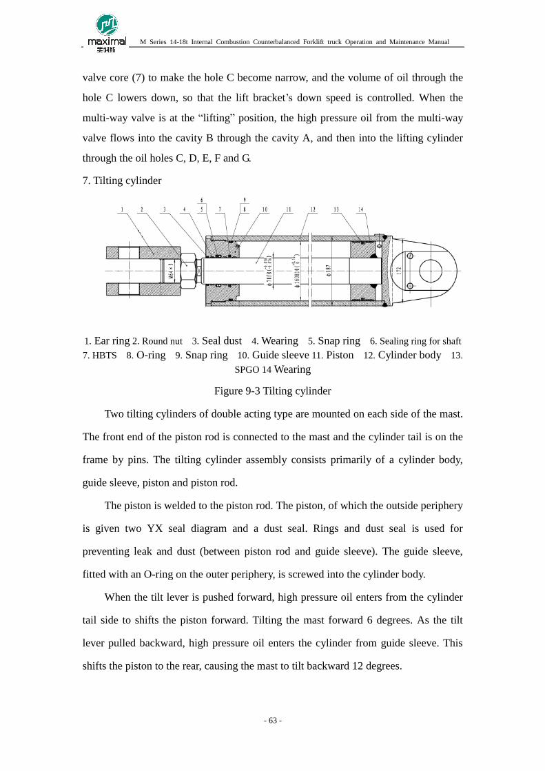
M Series 14-18t Internal Combustion Counterbalanced Forklift truck Operation and Maintenance Manual
- 63 -
valve core (7) to make the hole C become narrow, and the volume of oil through the
hole C lowers down, so that the lift bracket’s down speed is controlled. When the
multi-way valve is at the “lifting” position, the high pressure oil from the multi-way
valve flows into the cavity B through the cavity A, and then into the lifting cylinder
through the oil holes C, D, E, F and G.
7. Tilting cylinder
1. Ear ring 2. Round nut 3. Seal dust 4. Wearing 5. Snap ring 6. Sealing ring for shaft
7. HBTS 8. O-ring 9. Snap ring 10. Guide sleeve 11. Piston 12. Cylinder body 13.
SPGO 14 Wearing
Figure 9-3 Tilting cylinder
Two tilting cylinders of double acting type are mounted on each side of the mast.
The front end of the piston rod is connected to the mast and the cylinder tail is on the
frame by pins. The tilting cylinder assembly consists primarily of a cylinder body,
guide sleeve, piston and piston rod.
The piston is welded to the piston rod. The piston, of which the outside periphery
is given two YX seal diagram and a dust seal. Rings and dust seal is used for
preventing leak and dust (between piston rod and guide sleeve). The guide sleeve,
fitted with an O-ring on the outer periphery, is screwed into the cylinder body.
When the tilt lever is pushed forward, high pressure oil enters from the cylinder
tail side to shifts the piston forward. Tilting the mast forward 6 degrees. As the tilt
lever pulled backward, high pressure oil enters the cylinder from guide sleeve. This
shifts the piston to the rear, causing the mast to tilt backward 12 degrees.

M Series 14-18t Internal Combustion Counterbalanced Forklift truck Operation and Maintenance Manual
- 64 -
Sino-American Zhejiang Maximal Forklift Co., Ltd.
Address: No.1 Jinxin Road, Lushan Street, Fuyang, Zhejiang
Tel: 0571-63160118/63486999
Fax: 0571-63160107
Website: www.maxforklift.cn
E-mail: [email protected]
Zhejiang Maximal Forklift Co., Ltd. reserves the right and power of interpretation, modification and deletion of
the content of this manual. In case of any doubt, please contact company promptly.


