154
7.0 M Series Installation Guide

7.0
M Series Installation Guide

Lenel OnGuard® 7.0 M Series Installation GuideThis guide is item number DOC-1042-EN-US, revision 4.012, July 2014Copyright © 1997-2014 Lenel Systems International, Inc. Information in this document is subject to change without notice. No part of this document may be reproduced or transmitted in any form or by any means, electronic or mechanical, for any purpose, without the express written permission of Lenel Systems International, Inc.Non-English versions of Lenel documents are offered as a service to our global audiences. We have attempted to provide an accurate translation of the text, but the official text is the English text, and any differences in the translation are not binding and have no legal effect.The software described in this document is furnished under a license agreement and may only be used in accordance with the terms of that agreement. Lenel and OnGuard are registered trademarks of Lenel Systems International, Inc. Microsoft, Windows, and Windows Server are either registered trademarks or trademarks of Microsoft Corporation in the United States and/or other countries. Integral and FlashPoint are trademarks of Integral Technologies, Inc. Crystal Reports for Windows is a trademark of Crystal Computer Services, Inc. Oracle is a registered trademark of Oracle Corporation. Other product names mentioned in this User Guide may be trademarks or registered trademarks of their respective companies and are hereby acknowledged. Portions of this product were created using LEADTOOLS © 1991-2014 LEAD Technologies, Inc. ALL RIGHTS RESERVED.OnGuard includes ImageStream® Graphic Filters. Copyright © 1991-2014 Inso Corporation. All rights reserved. ImageStream Graphic Filters and ImageStream are registered trademarks of Inso Corporation.WarrantyLenel warrants that the product is free from defects in material and workmanship under normal use and service with proper maintenance for one year from the date of factory shipment. Lenel assumes no responsibility for products damaged by improper handling, misuse, neglect, improper installation, over-voltages, repair, alteration, or accident. This warranty is limited to the repair or replacement of the defective unit. In no event shall Lenel Systems International be liable for loss of use or consequential damages of any kind, however occasioned.There are no expressed warranties other than those set forth herein. Warranty expressly excludes third party additions, deletions and/or upgrades to this product, including those contained herein. Lenel does not make, nor intends, nor does it authorize any agent or representative to make any other warranties or implied warranties, and expressly excludes and disclaims all implied warranties of merchantability or fitness for a particular purpose.Returned units are repaired or replaced from a stock of reconditioned units. All returns must be accompanied by a return authorization number (RMA) obtained from the Lenel customer service department prior to returning or exchanging any product. The RMA number must appear on the outside of the shipping box and on the packing slip. Any items returned without an RMA number will not be accepted and will be returned at the customer’s expense. All returns must have transportation, insurance, and custom brokers’ fees prepaid.LiabilityIt is expressly understood and agreed that the interface should only be used to control exits from areas where an alternative method for exit is available. This product is not intended for, nor is rated for operation in life-critical control applications. Lenel Systems International is not liable under any circumstances for loss or damage caused by or partially caused by the misapplication or malfunction of the product. Lenel’s liability does not extend beyond the purchase price of the product.

M Series Installation Guide
Table of Contents
Hardware Installation Guidelines .........................................71. Introduction ............................................................................................ 9
2. Installation ............................................................................................ 102.1 Installation Outline .............................................................................................. 102.2 General Installation Rules ................................................................................... 112.3 Signal Transmission ........................................................................................... 112.4 Cabling ................................................................................................................ 122.5 Mounting ............................................................................................................. 122.6 Power Setup ....................................................................................................... 152.7 Wiring Controller Tamper and AC Power Fail Inputs .......................................... 18
3. Pre-Power Up Testing ......................................................................... 20
4. Troubleshooting ................................................................................... 214.1 Power Problems ................................................................................................. 214.2 Reader Problems ................................................................................................ 224.3 Door Strike Problems .......................................................................................... 234.4 Communication Problems ................................................................................... 244.5 Contacting Technical Support ............................................................................. 24
5. UL Certified Installations ...................................................................... 255.1 Power .................................................................................................................. 275.2 UL Certified Power Supplies ............................................................................... 275.3 Typical Combinations for UL Installations ........................................................... 285.4 UL Evaluated Readers and Card Formats .......................................................... 285.5 Additional UL Requirements ............................................................................... 29
LNL-3300-M5 Intelligent System Controller .......................316. Overview of the LNL-3300-M5 ............................................................. 33
7. Jumpers and Switches ......................................................................... 357.1 J4 Termination Jumper ....................................................................................... 357.2 DIP Switches ...................................................................................................... 357.3 Reset Switch ....................................................................................................... 35
8. Dual NIC Operation ............................................................................. 368.1 LNL-ETHLAN-MICR (Micro Serial Server) ......................................................... 368.2 ETHLAN-MCR Standoffs .................................................................................... 36
revision 4 — 3
Table of Contents
8.3 ETHLAN-MICR Addressing ................................................................................ 368.4 Establish Network Communication ..................................................................... 38
9. Wiring ................................................................................................... 399.1 Communication Wiring ........................................................................................ 399.2 Input Power, Enclosure Tamper, and Power Fault Input Wiring ......................... 40
10. Configuration ..................................................................................... 4110.1 Web Configuration ............................................................................................ 4110.2 Configuring the LNL-3300-M5 in the Host Application ...................................... 44
11. Other Functions ................................................................................. 4511.1 Memory and Real Time Clock Backup Battery ................................................. 4511.2 Bulk Erase Function .......................................................................................... 45
12. Status LEDs ....................................................................................... 46
13. Specifications ..................................................................................... 47
LNL-1100-20DI Input Control Module ................................4914. Overview of the LNL-1100-20DI ........................................................ 51
15. Setting the Device Address and Baud Rate ...................................... 53
16. Alarm Input Wiring ............................................................................. 55
17. Status LEDs ....................................................................................... 57
18. Specifications ..................................................................................... 58
LNL-1200-16DO Output Control Module ............................5919. Overview of the LNL-1200-16DO ...................................................... 61
20. Setting the Device Address and Baud Rate ...................................... 63
21. Digital Output Wiring .......................................................................... 65
22. Status LEDs ....................................................................................... 67
23. Specifications ..................................................................................... 68
4 — revision 4
M Series Installation Guide
LNL-1200-16DOR Output Control Module .........................6924. Overview of the LNL-1200-16DOR .................................................... 71
25. Setting the Device Address and Baud Rate ...................................... 73
26. Relay Output Wiring ........................................................................... 75
27. Status LEDs ....................................................................................... 78
28. Specifications ..................................................................................... 79
LNL-1320-2RP Dual Door Control Module .........................8129. Overview of the LNL-1320-2RP ......................................................... 83
30. Configuration ..................................................................................... 8530.1 Setting the Device Address and Baud Rate ..................................................... 8530.2 Setting the Reader Power Selection Jumper (J5) ............................................. 86
31. Reader Wiring .................................................................................... 8831.1 LNL-1320-2RP to Reader Wiring ...................................................................... 8831.2 Door Position Monitor and REX Input Wiring .................................................... 9131.3 Door Strike Wiring ............................................................................................. 94
32. Status LEDs ..................................................................................... 100
33. Specifications ................................................................................... 101
LNL-1320-S2RP Dual Door Control Module ....................10334. Overview of the LNL-1320-S2RP .................................................... 105
35. Configuration ................................................................................... 10735.1 Setting the Device Address and Baud Rate ................................................... 10735.2 Setting the Reader Power Selection Jumper (J5) ........................................... 108
36. Reader Wiring .................................................................................. 11036.1 LNL-1320-S2RP to Reader Wiring ................................................................. 11036.2 Door Position Monitor and REX Input Wiring .................................................. 11336.3 Door Strike Wiring ........................................................................................... 117
37. Status LEDs ..................................................................................... 123
38. Specifications ................................................................................... 124
revision 4 — 5

Table of Contents
LNL-1380-8RP Reader Interface Module .........................12539. Overview of the LNL-1380-8RP ....................................................... 127
40. Configuration ................................................................................... 12940.1 Setting the Device Address and Baud Rate ................................................... 12940.2 Setting the Reader Interface Power Selection Jumper (J3) ............................ 13040.3 Wiring .............................................................................................................. 131
41. Status LEDs ..................................................................................... 138
42. Specifications ................................................................................... 139
LNL-8000-MCOM RS-485 Interface Module ....................14143. Overview of the LNL-8000-MCOM .................................................. 143
44. Wiring ............................................................................................... 14444.1 Communication Wiring .................................................................................... 14444.2 Input Power Wiring ......................................................................................... 14544.3 Enclosure Tamper and Power Fault Wiring .................................................... 146
45. Specifications ................................................................................... 147
Index ................................................................................................................ 149
6 — revision 4

HARDWARE INSTALLATION GUIDELINES


M Series Installation Guide
1 Introduction
Important: In order to use the LNL-3300-M5 Intelligent System Controller (ISC), the Migration Controllers (CASI) license bit must be enabled.
The Lenel M Series is a user-configurable controller enclosure for use with the OnGuard access control and alarm management software platforms. The M5 controller provides distributed processing for the interface of access control readers, keypads, alarm inputs and outputs back to a host system computer. Distributed processing from the PXNplus CPU board within the M5 enclosure allows the controller to operate independent of the host system computer with the majority of access control and alarm monitoring decisions made locally at the controller.
The Lenel M Series provides instant response for door control and alarm sensing in the field, while leaving the host system computer with more processing power for quickly executing daily operations such as alarm response, database updates and reporting.
The Lenel M Series has five (5) card slots for controller boards. All boards plug into the controller backplane making field configuration and maintenance easy and economical.
The Lenel M Series additionally incorporates flash memory technology that provides the ability to receive its operating system and application remotely from the host system over the already established communications path. This allows future firmware upgrades centrally from the host system without requiring costly service trips to each location for firmware replacement. Both the modular design and the flash memory technology of the Lenel M Series provide a simple migration path when considering future host system upgrades.
The M5 controller consists of the following:
• Enclosure (all steel cabinet with key lock and tamper-switch-protected door)• Power supply (user-provided)• Battery backup power supply (user-provided)• LNL-3300-M5 Intelligent System Controller (ISC)
Options include:
• LNL-1100-20DI Input/Output Control Module• LNL-8000-MCOM RS-485 Interface Module• Reader Processing boards:
- LNL-1320-2RP Dual Door Control Module- LNL-1320-S2RP Supervised Dual Door Control Module- LNL-1380-8RP Reader Interface Module
• Output boards:- LNL-1200-16DO Digital Output Control Module- LNL-1200-16DOR Relay Output Control Module
revision 4 — 9

Hardware Installation Guidelines
2 Installation
2.1 Installation Outline
The following is a basic outline for installing and setting up the Lenel M Series system. Some steps may have been done depending on what was ordered. Some steps are optional, depending on the additional equipment to be used. These steps are noted.
Important: Do not apply power to any component until the installation is complete. Damage to the components may occur if power is incorrectly applied.
1. Determine the cable clamps needed and obtain them before starting the installation.During the installation, remember to:• Label all connections/cables for ease of maintenance.• Leave enough slack in the wiring so the cables can be “dressed”. This minimizes interference
during board removal or replacement.
2. Unpack your system. Refer to Introduction on page 9.
3. Mount the enclosure. Refer to Mounting on page 12.
4. Mount and install the power supply. Refer to Installing the Power Supply on page 15.
5. Mount and install the battery backup. Refer to Installing the Battery Backup on page 17.
6. Wire up the LNL-3300-M5 ISC. Be sure to configure and verify the switch settings. Refer to Wiring on page 39.
7. If using networked controllers, verify that your network is up and running.
8. Install the reader board(s) into the enclosure and wire up the readers to the controller. Be sure to configure and verify the switch settings, jumpers, and/or resistor packs.
9. If using digital inputs, insert the LNL-1100-DI into the enclosure and wire the inputs to the board. Be sure to configure and verify the switch settings. Refer to Overview of the LNL-1100-20DI on page 51.
10. If using digital outputs, insert either the LNL-1200-16DO or LNL-1200-16DOR into the enclosure and wire the outputs to the board. Be sure to configure and verify the switch settings. Refer to Overview of the LNL-1200-16DO on page 61 and Overview of the LNL-1200-16DOR on page 71.
11. Test the wiring before you apply power. Refer to Pre-Power Up Testing on page 20
12. Configure your controller. Configure the controller using the Integrated Configuration Tool (ICT). Refer to Web Configuration on page 41.
10 — revision 4

M Series Installation Guide
2.2 General Installation Rules
Important: This equipment is to be installed, maintained and serviced by authorized service persons only.
The authorized installation contractor should comply with the following rules:
• Neatly label cables at both ends.(For example, labels should include: controller address number/device or reader number)
• Use individually shielded pairs of cables only. All wiring must comply with local, state, and federal electrical codes and fire codes.
• Obey all national, state, and local electrical and safety codes.• Obtain any required permits and/or inspections. Contact the local fire marshal for assistance if
necessary.• Safety of customer personnel is the primary consideration of the installation.• Neatly dress and tie or lace all wiring in a professional manner.• Gather together and tape all unused conductors in multiple conductor cables.• Shield all cabling and terminate properly.
Notes: This is an FCC Class A product. In a domestic environment, this product may cause radio interference in which case the user may be required to take adequate measures.
Circuit board components are vulnerable to damage by electrostatic discharge (ESD). ESD can cause immediate or subtle damage to sensitive electronic parts. An electrostatic charge can build up on the human body and then discharge when you touch a board. A discharge can be produced when walking across a carpet and touching a board, for example. Before handling any board, make sure you dissipate your body’s charge by touching ground. This discharges any static electricity build-up.
2.3 Signal Transmission
• Where practical, keep cables well separated from each other. Separate power cables from signal cables.• Keep the break-out at the ends of signal cables as short as possible.• Ground all shield drain wire(s) at the M5 controller using the grounding studs provided outside the
cabinet enclosure. • For communication cables between controllers, ground shield to the upstream controller only.
Note: Do not ground both cable ends.
revision 4 — 11
Hardware Installation Guidelines
2.4 Cabling
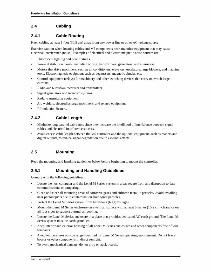
2.4.1 Cable RoutingKeep cabling at least 1 foot (30.5 cm) away from any power line or other AC voltage source.
Exercise caution when locating cables and M5 components near any other equipment that may cause electrical interference (noise). Examples of electrical and electro-magnetic noise sources are:
• Fluorescent lighting and neon fixtures.• Power distribution panels, including wiring, transformers, generators, and alternators.• Motors that drive machinery, such as air conditioners, elevators, escalators, large blowers, and machine
tools. Electromagnetic equipment such as degaussers, magnetic chucks, etc. • Control equipment (relays) for machinery and other switching devices that carry or switch large
currents.• Radio and television receivers and transmitters. • Signal generators and intercom systems. • Radar transmitting equipment.• Arc welders, electrodischarge machinery, and related equipment.• RF induction heaters.
2.4.2 Cable Length• Minimize long parallel cable runs since they increase the likelihood of interference between signal
cables and electrical interference sources.• Avoid excess cable length between the M5 controller and the optional equipment, such as readers and
digital outputs, to reduce signal degradation due to external effects.
2.5 Mounting
Read the mounting and handling guidelines below before beginning to mount the controller.
2.5.1 Mounting and Handling GuidelinesComply with the following guidelines:
• Locate the host computer and the Lenel M Series system in areas secure from any disruption to data communications or tampering.
• Clean and clear all mounting areas of corrosive gases and airborne metallic particles. Avoid installing near photocopiers due to contamination from toner particles.
• Protect the Lenel M Series system from hazardous (high) voltages.• Mount the Lenel M Series enclosure on a vertical surface with at least 6 inches (15.2 cm) clearance on
all four sides to support thermal air cooling.• Locate the Lenel M Series enclosure in a place that provides dedicated AC earth ground. The Lenel M
Series system must be earth grounded.• Keep interior and exterior housing of all Lenel M Series enclosures and other components free of wire
remnants.• Avoid temperatures outside range specified for Lenel M Series operating environment. Do not leave
boards or other components in direct sunlight.• To avoid mechanical damage, do not drop or stack boards.
12 — revision 4

M Series Installation Guide
• Do not subject printed circuit boards to electrostatic discharge.
2.5.2 Mounting Instructions
Note: Do not apply power to any component during installation. Damage to components may occur if power is incorrectly applied.
Mount the controller enclosure using the following steps.
1. Remove the packing material from the enclosure.
2. Unscrew four (4) nuts to remove card cage. Use socket wrench for #10 nuts.
3. Using the template provided, mark and drill four (4) mounting holes.
4. Using customer furnished 1/4-in. (6 mm) threaded lag bolts or equivalent and washers, secure the enclosure to the wall. Replace the card cage.
5. If required, install cable conduit to the enclosure knockout holes.The enclosure has knockout holes on three sides. To open the holes, strike the knockouts from outside the cabinet. Then pull the cable through the holes.
6. Fit and tighten approved strain relief clamp in each knockout hole to be used.
Note: The enclosure must be grounded.
7. Find the nearest earth ground (electrical box, ground bus, etc.). Run wire from the M5 cabinet ground terminal (cabinet bottom left) to earth ground point. Use wire size in accordance with local and national electrical codes.
revision 4 — 13

Hardware Installation Guidelines
Controller and Components Assembly Drawing in Standard Enclosure
Controller and Components Assembly Drawing in Standard Enclosure Callouts
Callout Description
1 Mounting surface
2 Lenel M Series enclosure
3 Tamper switch
4 Card cage for printed circuit boards
5 Slot J7
6 LNL-3300-M5 in Slot J7 (first controller enclosure)LNL-8000-MCOM in Slot J7 (downstream controller enclosures)
7 Slot J6 (empty)
1
2
34
5 6
7
8
9
10
11
12
13
14
15
14 — revision 4

M Series Installation Guide
The Lenel M Series requires a 12 VDC, 3 A minimum, power supply. Depending on system configuration, a larger power supply may be required.
Note: For downstream controller enclosures, connect power to the LNL-8000-MCOM using the same steps and guidelines to connect power to the LNL-3300-M5.
2.6 Power Setup
2.6.1 Installing the Power Supply
Notes: A readily accessible disconnect device shall be incorporated in the building installation wiring.
This equipment has been designed for connection to an IT power distribution system.
1. Mount the power supply as close to the controller enclosure as possible.
2. Run the wire through the knockout hold to the following terminals on the LNL-3300-M5 ISC:• TB1-3: VIN (+12 VDC)• TB1-4: GND (12 VDC return)Connect power with 18 AWG minimum.
Note: There are three pairs of power connections on the LNL-3300-M5 ISC, all are in parallel. If needed the other two pairs can supply power to the I/O boards.
8 Slots J1 through J5: printed circuit boards
9 Component side of printed circuit boards
10 Solder side of printed circuit boards
11 Slot J1
12 Internal ground stud bracket
13 Ground for cable shield termination
14 Enclosure height: 12.700 in. (322.58 mm)
15 Enclosure width: 7.875 in. (200.02 mm)
Controller and Components Assembly Drawing in Standard Enclosure Callouts
Callout Description
revision 4 — 15

Hardware Installation Guidelines
Power Supply Wiring
3. Install the enclosure ground complying with the following guidelines:• Provide a dedicated AC ground for each controller.• Find the nearest earth ground, such as an electrical box or a ground bus.• Run a 14-18 AWG wire from the controller enclosure ground stud (located at the enclosure bottom
left) to the earth ground point.
Notes: Controller earth grounding (AC grounding) is a critical element for proper operation.
Connect the GND signal to earth ground in one location within the system. Multiple earth ground connections are not recommended and can cause ground loop problems.
Test AC power ground to ensure proper earth grounding. Using an ohmmeter, measure the resistance between the enclosure ground stud and a known good earth ground (metal water
Power Supply Wiring Callouts
Callout Description
1 Power supply (110/220 VAC input)
2 TB1 terminal block on LNL-3300-M5 ISC
3 TB1-3: +12 VDC connection
4 TB1-4: Ground (12 VDC return)
1
2
GND
VIN
TB1
VIN
GND
GND
VIN
PFLT
TMPR
+
-
3
4
3
4
16 — revision 4

M Series Installation Guide
pipe or building structural steel frame). If resistance is greater than 50 ohms, it indicates poor AC ground. A good earth ground must be made before completing the installation.
Do not ground both cable ends.
Observe polarity on the 12 VDC input. If the polarity is reversed, the fuse will blow to prevent damage. If the fuse blows, replace with a fuse of the same type and rating.
2.6.2 Installing the Battery BackupThe battery backup acts as a temporary power supply to the Lenel M Series when AC power is lost. Figure X shows a typical wiring between a battery backup power supply and an LNL-3300-M5 ISC. For specific wiring information, refer to the documentation supplied with the battery backup unit.
Note: Make sure all power (AC input and battery backup) is disconnected before installing any of the printed circuit boards.
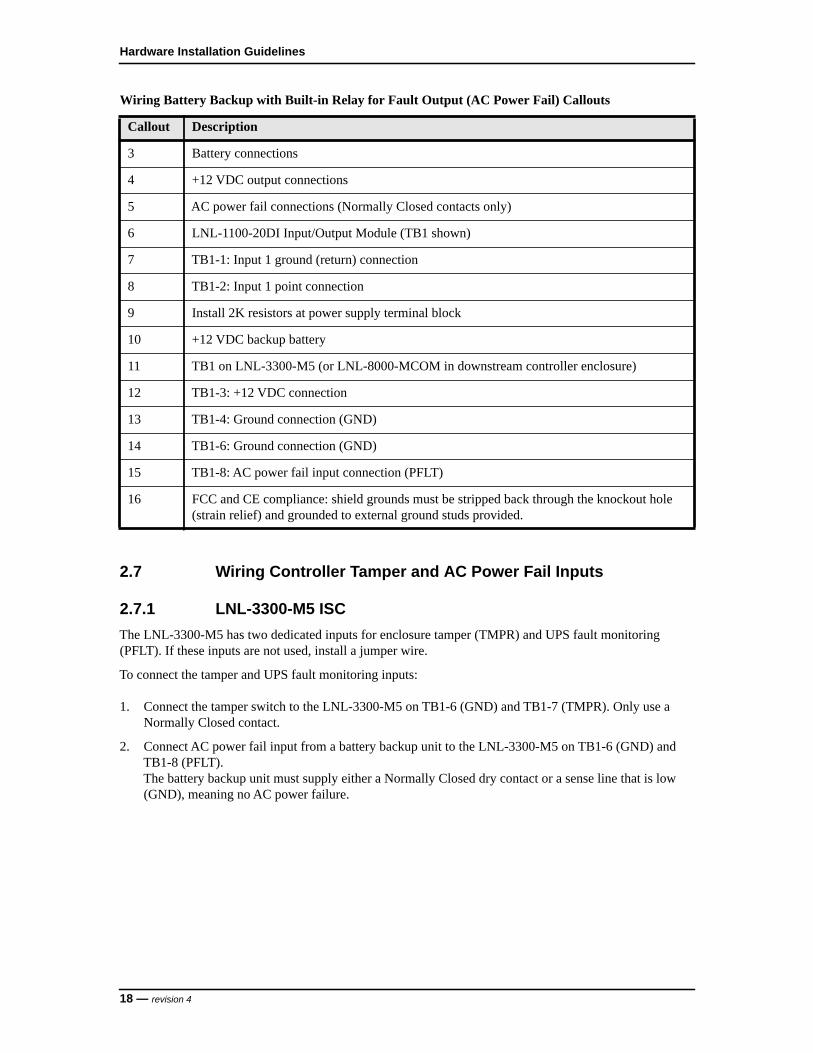
Wiring Battery Backup with Built-in Relay for Fault Output (AC Power Fail)
Wiring Battery Backup with Built-in Relay for Fault Output (AC Power Fail) Callouts
Callout Description
1 Battery backup power supply (installer supplied)
2 Low battery connections (Normally Closed contacts only)
1
2
3
4
NC
COM
NO
NC
COM
+
-+
-
8
3
4
TB1
6
1
TB1
22K 2K
+
-
GND
5
6
7
89
10
11
12
13
14
15
16
revision 4 — 17
Hardware Installation Guidelines
2.7 Wiring Controller Tamper and AC Power Fail Inputs
2.7.1 LNL-3300-M5 ISCThe LNL-3300-M5 has two dedicated inputs for enclosure tamper (TMPR) and UPS fault monitoring (PFLT). If these inputs are not used, install a jumper wire.
To connect the tamper and UPS fault monitoring inputs:
1. Connect the tamper switch to the LNL-3300-M5 on TB1-6 (GND) and TB1-7 (TMPR). Only use a Normally Closed contact.
2. Connect AC power fail input from a battery backup unit to the LNL-3300-M5 on TB1-6 (GND) and TB1-8 (PFLT).The battery backup unit must supply either a Normally Closed dry contact or a sense line that is low (GND), meaning no AC power failure.
3 Battery connections
4 +12 VDC output connections
5 AC power fail connections (Normally Closed contacts only)
6 LNL-1100-20DI Input/Output Module (TB1 shown)
7 TB1-1: Input 1 ground (return) connection
8 TB1-2: Input 1 point connection
9 Install 2K resistors at power supply terminal block
10 +12 VDC backup battery
11 TB1 on LNL-3300-M5 (or LNL-8000-MCOM in downstream controller enclosure)
12 TB1-3: +12 VDC connection
13 TB1-4: Ground connection (GND)
14 TB1-6: Ground connection (GND)
15 TB1-8: AC power fail input connection (PFLT)
16 FCC and CE compliance: shield grounds must be stripped back through the knockout hole (strain relief) and grounded to external ground studs provided.
Wiring Battery Backup with Built-in Relay for Fault Output (AC Power Fail) Callouts
Callout Description
18 — revision 4
M Series Installation Guide
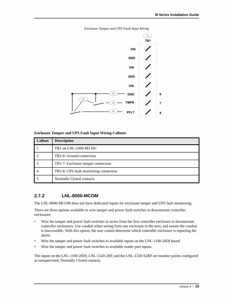
Enclosure Tamper and UPS Fault Input Wiring
2.7.2 LNL-8000-MCOMThe LNL-8000-MCOM does not have dedicated inputs for enclosure tamper and UPS fault monitoring.
There are three options available to wire tamper and power fault switches in downstream controller enclosures:
• Wire the tamper and power fault switches in series from the first controller enclosure to downstream controller enclosures. Use conduit when wiring from one enclosure to the next, and ensure the conduit is inaccessible. With this option, the user cannot determine which controller enclosure is reporting the alarm.
• Wire the tamper and power fault switches to available inputs on the LNL-1100-20DI board.• Wire the tamper and power fault switches to available reader port inputs.
The inputs on the LNL-1100-20DI, LNL-1320-2RP, and the LNL-1320-S2RP are monitor points configured as unsupervised, Normally Closed contacts.
Enclosure Tamper and UPS Fault Input Wiring Callouts
Callout Description
1 TB1 on LNL-3300-M5 ISC
2 TB1-6: Ground connection
3 TB1-7: Enclosure tamper connection
4 TB1-8: UPS fault monitoring connection
5 Normally Closed contacts
1
GND
VIN
TB1
VIN
GND
GND
VIN
PFLT
TMPR
8
6
7
2
3
4
5
revision 4 — 19

Hardware Installation Guidelines
3 Pre-Power Up Testing
Follow the steps below before powering up the controller.
1. Measure the AC power supplied to the power supply (110 VAC or 220 VAC, depending on the power supply installed).
Note: The power supply must have a dedicated circuit breaker. Do not plug into an outlet that is controlled by an on/off switch.
2. Using an ohmmeter, test the reader power wiring to determine if a short circuit exists. Unplug each reader connector and measure, from the reader connector going out to the readers between the + pin (VO or 12V) to chassis and the + pin to the ground pin. Refer to the following list of terminal blocks and pins for more information:
- LNL-1320-2RP and LNL-1320-S2RP:– Reader Port 1: TB1-1: VO; TB1-2: GND– Reader Port 2: TB3-1: VO; TB3-2: GND
- LNL-1380-8RP:– Reader Port 1: TB1-1: 12V; TB1-2: GND– Reader Port 2: TB1-5: 12V; TB1-6: GND– Reader Port 3: TB2-1: 12V; TB2-2: GND– Reader Port 4: TB2-5: 12V; TB2-6: GND– Reader Port 5: TB3-1: 12V; TB3-2: GND– Reader Port 6: TB3-5: 12V; TB3-6: GND– Reader Port 7: TB4-1: 12V; TB4-2: GND– Reader Port 8: TB4-5: 12V; TB4-6: GND
Result: A measurement of less than 100 ohms indicates a short circuit. Correct this condition before applying power to the system.
3. If an LNL-1200-16DO is installed, check for a short circuit. Unplug each connector and measure from chassis ground to all pins on the LNL-1200-16DO connector.Result: A measurement of less than 100 ohms indicates a short circuit. Trace out the wiring to locate the short circuit.
4. Reconnect all connectors.
5. On the LNL-3300-M5, disconnect the power input connector from Terminal Block 1 (TB1).
6. Use a voltmeter to measure the input voltage across TB1-3 (VIN) and TB1-4 (GND) on the LNL-3300-M5.Result: If the voltmeter reads -12 to -15 VDC, the wires are reversed.
Solution: Reverse the wires on TB1-3 (VIN) and TB1-4 (GND) so TB1-3 is the + voltage. The voltmeter should read +12 to +15 VDC.
7. Reconnect the power input connector from TB1 connector removed in Step 5.
8. Apply power to the system.
20 — revision 4
M Series Installation Guide
4 Troubleshooting
This section provides information to help diagnose and solve various problems that may arise while configuring or using the Lenel M Series and offers technical support contacts in case assistance is needed.
Refer to the appropriate section:
• Power Problems on page 21 • Reader Problems on page 22 • Door Strike Problems on page 23 • Communication Problems on page 24• Contacting Technical Support on page 24
4.1 Power Problems
Problem: The Lenel M Series does not power up correctly.
Resolution: Verify that the Status LEDs on the LNL-3300-M5 ISC are on. Refer to figure LNL-3300-M5 Board on page 33. If these LEDs are not ON per the stated operation in Status LEDs on page 46, do the following:
1. Use a voltmeter to check the power supply output. It should read 12 to 15 VDC. If there is no output, make sure the power supply is not on a switched outlet. Be sure the circuit breaker for the power supply is not tripped.
2. Make sure the power input connector is properly seated in TB1 on the LNL-3300-M5.
3. Make sure the LNL-3300-M5 is seated properly into the backplane and that no pins are bent on J6, the 48-pin connector.
4. Disconnect the power input connector from TB1 on the LNL-3300-M5. Remove the LNL-3300-M5 and inspect the fuse. If the fuse is blown, replace it.
Note: Replace the fuse with one of the same type and rating. Do not power the unit back on until the problem is identified and corrected.
a. Make sure that the wiring connections from the power supply to the LNL-3300-M5 are not reversed. If these connections are OK, go to Step 4b.
b. Use an ohmmeter to check the resistance between TB1-3 (VIN) and TB1-4 (GND) on the LNL-3300-M5. If the resistance is less than 200 ohms, there is a short from power to ground. Isolate the fault by doing the following:– Remove all boards from the backplane except the LNL-3300-M5. Add each board while
measuring the resistance on J6 pins 3 and 4. When the resistance falls below 200 ohms while a board is plugged in, isolate the board. Continue checking the remaining boards for other ground faults.
– Remove connectors one by one on the faulty boards until the fault condition disappears (resistance goes above 200 ohms). Trace out wiring on these connectors to find and correct the problem.
revision 4 — 21

Hardware Installation Guidelines
4.2 Reader Problems
Consult your reader installation manual for potential problems that are not related to the LNL-3300-M5 controller. Also refer to the following sections:
• Using the LNL-1320-2RP on page 22• Using the LNL-1320-S2RP on page 22• Using the LNL-1380-8RP on page 23
4.2.1 Using the LNL-1320-2RPProblem: The reader does not power up.
Resolution:
1. Make sure that the reader selection voltage jumper (JP5) on the LNL-1320-2RP is properly set. Refer to Setting the Reader Power Selection Jumper (J5) on page 86.
Caution: Do not set JP5 to 12 V for a 5 V reader. Doing so may permanently damage the reader.
2. Make sure that the proper resistor packs are installed in the LNL-1320-2RP. Refer to Installing Resistor Packs on page 34.
3. Check the wiring between the LNL-1320-2RP board and the reader. Refer to Reader Wiring on page 88 and the reader installation manual.
4. Make sure the connectors are firmly seated in TB1 (Reader Port 1) and TB3 (Reader Port 2) on the LNL-1320-2RP board.
Problem: The reader has power, but the Status LEDs 1 (Reader Port 1) and 2 (Reader Port 2) on the LNL-1320-2RP do not flash at all (no reader activity).
Resolution:
1. Make sure that the resistor packs are installed and are the correct value for the reader type being used.
2. Make sure that the DIP switch settings on the LNL-1320-2RP for address and reader technology/format are correct. Refer to Setting the Device Address and Baud Rate on page 85.
3. Check the wiring between the reader and the LNL-1320-2RP. Refer to Reader Wiring on page 88 and the reader installation manual.
4.2.2 Using the LNL-1320-S2RPProblem: The reader does not power up.
Resolution:
1. Make sure that the reader selection voltage jumper (JP5) on the LNL-1320-S2RP is properly set. Refer to Setting the Reader Power Selection Jumper (J5) on page 108.
22 — revision 4
M Series Installation Guide
Caution: Do not set JP5 to 12 V for a 5 V reader. Doing so may permanently damage the reader.
2. Make sure that the proper resistor packs are installed in the LNL-1320-S2RP. Refer to Installing Resistor Packs on page 34.
3. Check the wiring between the LNL-1320-S2RP board and the reader. Refer to Reader Wiring on page 110 and the reader installation manual.
4. Make sure the connectors are firmly seated in TB1 (Reader Port 1) and TB3 (Reader Port 2) on the LNL-1320-S2RP board.
Problem: The reader has power, but the Status LEDs 1 (Reader Port 1) and 2 (Reader Port 2) on the LNL-1320-S2RP do not flash at all (no reader activity).
Resolution:
1. Make sure that the resistor packs are installed and are the correct value for the reader type being used.
2. Make sure that the DIP switch settings on the LNL-1320-S2RP for address and reader technology/format are correct. Refer to Setting the Device Address and Baud Rate on page 107.
3. Check the wiring between the reader and the LNL-1320-S2RP. Refer to Reader Wiring on page 110 and the reader installation manual.
4.2.3 Using the LNL-1380-8RPProblem: The reader does not power up.
Resolution:
1. Check the wiring between the LNL-1380-8RP board and the reader. Refer to Wiring on page 131 and the reader installation manual.
2. Make sure the connectors are firmly seated in the terminal block for the affected reader on the LNL-1380-8RP board.
Problem: The reader has power, but Status LED 3 on the LNL-1380-8RP do not flash at all (no reader activity).
Resolution:
1. Make sure that the DIP switch settings on the LNL-1380-8RP for address and reader technology/format are correct. Setting the Device Address and Baud Rate on page 129.
2. Check the wiring between the reader and the LNL-1380-8RP. Refer to Wiring on page 131 and the reader installation manual.
4.3 Door Strike Problems
Problem: The door reader LED lights on the reader, but the door strike does not operate.
Resolution:
1. Check the wiring from the door strike to the reader board. Also refer to the door strike manufacturer’s installation instructions.
revision 4 — 23
Hardware Installation Guidelines
Make sure the door strike power supply is operating properly.
4.4 Communication Problems
Problem: The central supervisory station received a “Communication Loss” message.
Resolution: A compromise attempt may have occurred on the communication line. Check the line for integrity. Ensure all connections are made and are intact.
4.5 Contacting Technical Support
For assistance installing, operating, maintaining, and troubleshooting this product, refer to this document and any other documentation provided. If you still have questions, contact Lenel Technical Support during normal business hours (Monday through Friday, excluding holidays, between 8:30 a.m. and 5:30 p.m., Eastern Time).
Please be ready at the equipment before calling for technical support.
• Toll Free: 866-788-5095• Fax Line: +1 585-248-9185• Email: [email protected]• Web site: www.lenel.com
24 — revision 4

M Series Installation Guide
5 UL Certified Installations
The system is to be installed within a protected premise. In a subassembly, the operating temperature range must be 0° to 49°C (32° to 120°F); the humidity range must be 0 to 85% RH.
This system must be installed in accordance with the National Electrical Code (NFPA 70), and the local authority having jurisdiction.
For UL Installations, the central supervisory station equipment must be UL Listed to:
• Information Technology Equipment, UL 60950
For UL Installations, use UL Listed information technology equipment. The computer minimum platform requirements are as follows:
• Intel Pentium 4 dual core processor
• 3.4 GHz clock speed
• 4 GB RAM
• 6 GB of hard drive space for OnGuard
• DVD-ROM drive
• One (1) USB port
• Operating systems:- Windows Server 2012 R2- Windows Server 2012- Windows Server 2008 R2- Windows 8/Windows 8.1- Windows 7 SP1
• Database systems:- Microsoft SQL Server 2014 (32 and 64-bit) and Express- Microsoft SQL Server 2012 SP1 (32 and 64-bit), or SQL 2012 Express- Microsoft SQL Server 2008 R2 SP2 (32 and 64-bit)- Microsoft SQL Server 2008 R2 SP1 (32 and 64-bit)- Microsoft SQL Server 2008 SP2, SP3 (32 and 64-bit)- Oracle 12cR1 Server 64-bit (12.1.0.1) with 32-bit Client installed if OnGuard is running on the
same server as the database- Oracle 11g R2 Server 64-bit (11.2.03 and 11.2.04) with 32-bit Client installed if OnGuard is
running on the same server as the database- Oracle 11g R2 Server 32-bit (11.2.03 and 11.2.04)- Oracle 11g R1 Server 64-bit (11.1.0.7) with 32-bit Client installed if OnGuard is running on the
same server as the database- Oracle 11g R1 Server 32-bit (11.1.0.6)
• Access control/proprietary burglary systems:- OnGuard 7.x (7.x.xxx) using DOC-1042-EN-US M Series Installation Guide
• The LNL-3300-M5 ISC must have firmware version 1.188 or later installed
• NEC ExpressCluster X R3 Fault Tolerant software (pending)
The following devices must be incorporated into the system:
revision 4 — 25

Hardware Installation Guidelines
• Supply line transient protection complying with the Standard for Transient Voltage Surge Suppressors, UL 1449, with a maximum marked rating of 330 V.
• Signal line transient protection complying with the Standard for Protectors for Data Communications and Fire Alarm Circuits, UL 497B, with a maximum marked rating of 50 V.
Equipment must be installed in a temperature controlled environment, maintained between 0° and 49°C (32° and 120°F) by the HVAC system. 24 hours of standby must be provided for the HVAC system.
HVAC rated modules were not evaluated by UL for Lenel OnGuard UL1076 product Listing.
In addition to the main power supply and secondary power supply that are required to be provided at the central supervisory station, the system must be provided with an uninterruptable power supply (UPS) with sufficient capacity to operate the computer equipment for a minimum of 15 minutes. If more than 15 minutes is required for the secondary power supply to supply the UPS input power, the UPS must be capable of providing input power for at least that amount of time. A means for disconnecting the input to the UPS while maintaining continuity of power to the automation system must be provided, in order to perform maintenance and repair service.
The UPS must comply with the Standard for Uninterruptable Power Supply Equipment, UL1778 or the Standard for Fire Protective Signaling Devices, UL1481.
Be sure to use the recommended cabling, which is the shielded wiring required for use on all modules.
Communication circuits and network components connected to the telecommunications network shall be protected by secondary protectors for communication circuits. These protectors shall comply with the Standard for Secondary Protectors or Communications Circuits, UL 497A. These protectors shall be used only in the protected side of the telecommunications network.
A metal conduit must be used when connecting all UL enclosures. This is required for all UL installations.
Do not exceed 1000 receiver accounts for UL.
All receiving equipment shall be completely duplicated with provision for switchover to the backup system within 30 seconds. The backup system shall be fully operational within 6 minutes of the loss of the primary system. This allows 30 seconds for the backup system to be fully energized and connected to the necessary communication lines and other devices, followed by 5-1/2 minutes for the system to boot up, conduct memory tests, file system check, security verifications, and prepare for full system operation. The backup computer must have the capabilities of the primary, such as memory, speed, and the like.
Failure of the main computer system, hard disk, and alarm monitor must be programmed to switchover to the backup system, and indicate an audible, or obvious visual indication.
A fault tolerant system may be used in lieu of complete duplication of the system if every component in the fault tolerant system, including the software and power supply, is duplicated.
All OnGuard system solutions that are to be UL1076 compliant systems must also meet the requirements specified in Section 25A of the UL1076 (Proprietary Burglar Alarm Units and Systems Standard for Safety). This requirement outlines the need for host monitoring redundancy. Host monitoring redundancy can be accomplished in many ways, but the standard is clear as to receiving equipment methods, recovery time, surge suppression and system configurations. Contact Lenel if configuration assistance is required.
All inputs must be supervised for UL1076 installations.
26 — revision 4
M Series Installation Guide
Priority features (alarm, loss of line voltage, opens, shorts, etc.) must be programmed for an audio and a visual indication at the central supervisory station equipment, and to create a printout. The condition must be recorded. This indication shall not be silenced without acknowledgment.
Bypass of protective features, such as auto-bypass for forced arm, must not be programmed for UL.
The Ethernet connection must be maintained continuously.
Use Marking — Commercial, Proprietary, Multiplex, Encrypted Line Security Burglar Alarm System Control Unit and Access Control Unit.
Lenel AES Firmware is embedded (installed) in the LNL-3300-M5 (firmware version 1.188) for suitability as “Encrypted Line Security Equipment.”
Note: If the central supervisory station receives a “Communication Loss” message, a compromise attempt on the communication line may have occurred.
Network addressing of devices shall not make use of public domain name servers.
Panic hardware must be UL 305 Listed.
5.1 Power
The standby power system for the HVAC system may be supplied by an engine-driven generator alone. Use of a standby battery is not required.
All external interconnecting power sources must be UL Listed access control/proprietary burglar power limited power supplies. AC supply lines shall not be routed in the same conduit or harness as low voltage lines.
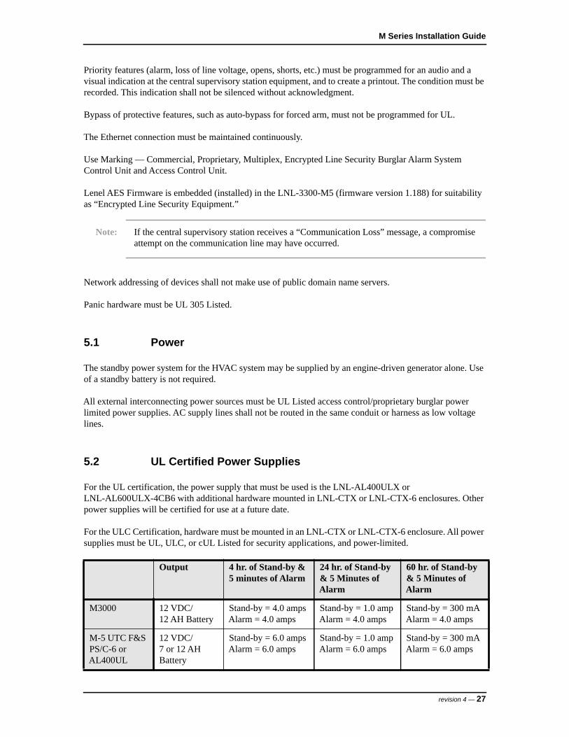
5.2 UL Certified Power Supplies
For the UL certification, the power supply that must be used is the LNL-AL400ULX or LNL-AL600ULX-4CB6 with additional hardware mounted in LNL-CTX or LNL-CTX-6 enclosures. Other power supplies will be certified for use at a future date.
For the ULC Certification, hardware must be mounted in an LNL-CTX or LNL-CTX-6 enclosure. All power supplies must be UL, ULC, or cUL Listed for security applications, and power-limited.
Output 4 hr. of Stand-by & 5 minutes of Alarm
24 hr. of Stand-by & 5 Minutes of Alarm
60 hr. of Stand-by & 5 Minutes of Alarm
M3000 12 VDC/12 AH Battery
Stand-by = 4.0 ampsAlarm = 4.0 amps
Stand-by = 1.0 ampAlarm = 4.0 amps
Stand-by = 300 mAAlarm = 4.0 amps
M-5 UTC F&S PS/C-6 or AL400UL
12 VDC/7 or 12 AH Battery
Stand-by = 6.0 ampsAlarm = 6.0 amps
Stand-by = 1.0 ampAlarm = 6.0 amps
Stand-by = 300 mAAlarm = 6.0 amps
revision 4 — 27

Hardware Installation Guidelines
5.3 Typical Combinations for UL Installations
The following combinations must be used in a UL type installation with OnGuard 7.x or later, which are approved for use. For UL certification, a UL Listed power supply and one of the following enclosures must be used:
- M/5- M/5-E- M/5-P- M5-PX- M/5-PXN- M/5-PXNplus- Micro5- Micro5-E- Micro5-P- Micro5-PX- Micro5-PXN- Micro5-PXNplus- Mirco/5- Micro/5-E- Micro/5-P- Micro/5-PX- Micro/5-PXN- Micro/5-PXN- Micro/5-PXNplus- M5- M5-E- M5-P- M5-PX- M5-PX- M5-PXN- M5-PXNplus- M3000- M3000-PXNplus- M3PPMSP- M3PPMSP-DN- M3PPMPP
Multiple combinations of Lenel access hardware can be used within the UL approved enclosure.
The minimum configuration for the M Series consists of a UL approved enclosure and the LNL-3300-M5 ISC.
For proprietary burglar alarm applications, the LNL-1100-20DI Input Control Module is required.
For access control applications, one of the following is required:- LNL-1320-2RP Dual Door Control Modules- LNL-1320-S2RP Supervised Dual Door Control Module- LNL-1380-8RP Reader Interface Module is required
5.4 UL Evaluated Readers and Card Formats
All card readers must be evaluated by UL, must be ULC or cUL Listed, and be Wiegand compatible.
28 — revision 4
M Series Installation Guide
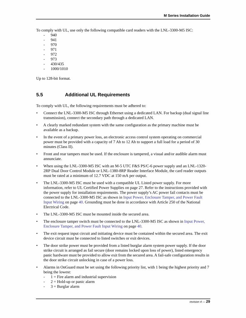
To comply with UL, use only the following compatible card readers with the LNL-3300-M5 ISC:- 940- 941- 970- 971- 972- 973- 430/435- 1000/1010
Up to 128-bit format.
5.5 Additional UL Requirements
To comply with UL, the following requirements must be adhered to:
• Connect the LNL-3300-M5 ISC through Ethernet using a dedicated LAN. For backup (dual signal line transmission), connect the secondary path through a dedicated LAN.
• A clearly marked redundant system with the same configuration as the primary machine must be available as a backup.
• In the event of a primary power loss, an electronic access control system operating on commercial power must be provided with a capacity of 7 Ah to 12 Ah to support a full load for a period of 30 minutes (Class II).
• Front and rear tampers must be used. If the enclosure is tampered, a visual and/or audible alarm must annunciate.
• When using the LNL-3300-M5 ISC with an M-5 UTC F&S PS/C-6 power supply and an LNL-1320-2RP Dual Door Control Module or LNL-1380-8RP Reader Interface Module, the card reader outputs must be rated at a minimum of 12.7 VDC at 150 mA per output.
• The LNL-3300-M5 ISC must be used with a compatible UL Listed power supply. For more information, refer to UL Certified Power Supplies on page 27. Refer to the instructions provided with the power supply for installation requirements. The power supply’s AC power fail contacts must be connected to the LNL-3300-M5 ISC as shown in Input Power, Enclosure Tamper, and Power Fault Input Wiring on page 40. Grounding must be done in accordance with Article 250 of the National Electrical Code.
• The LNL-3300-M5 ISC must be mounted inside the secured area.
• The enclosure tamper switch must be connected to the LNL-3300-M5 ISC as shown in Input Power, Enclosure Tamper, and Power Fault Input Wiring on page 40.
• The exit request input circuit and initiating device must be contained within the secured area. The exit device circuit must be connected to listed switches or exit devices.
• The door strike power must be provided from a listed burglar alarm system power supply. If the door strike circuit is arranged as fail secure (door remains locked upon loss of power), listed emergency panic hardware must be provided to allow exit from the secured area. A fail-safe configuration results in the door strike circuit unlocking in case of a power loss.
• Alarms in OnGuard must be set using the following priority list, with 1 being the highest priority and 7 being the lowest:- 1 = Fire alarm and industrial supervision- 2 = Hold-up or panic alarm- 3 = Burglar alarm
revision 4 — 29

Hardware Installation Guidelines
- 4 = Watchman or guard tour- 5 = Fire-alarm supervision- 6 = Burglar-alarm supervision- 7 = Industrial supervision
• The number of separate signals on a single channel must be limited to 1000.
30 — revision 4
LNL-3300-M5 INTELLIGENT SYSTEM CONTROLLER

M Series Installation Guide
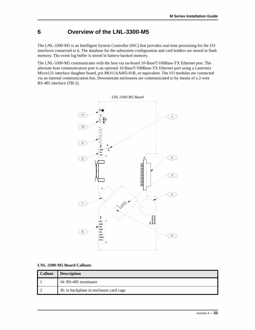
6 Overview of the LNL-3300-M5
The LNL-3300-M5 is an Intelligent System Controller (ISC) that provides real-time processing for the I/O interfaces connected to it. The database for the subsystem configuration and card holders are stored in flash memory. The event log buffer is stored in battery-backed memory.
The LNL-3300-M5 communicates with the host via on-board 10-BaseT/100Base-TX Ethernet port. The alternate host communication port is an optional 10-BaseT/100Base-TX Ethernet port using a Lantronix Micro125 interface daughter board, p/n MO11AA003-01R, or equivalent. The I/O modules are connected via an internal communication bus. Downstream enclosures are communicated to by means of a 2-wire RS-485 interface (TB-2).
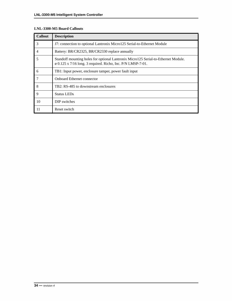
LNL-3300-M5 Board
LNL-3300-M5 Board Callouts
Callout Description
1 J4: RS-485 terminator
2 J6: to backplane in enclosure card cage
11
9
8
6
4
2
3
5
7
1
10
S22
34
12
64
53
1S1
ON
J4
BT1
J6
TB1
J1
BR
/CR
2325
BR
/CR
2330
TB2
J7
18
13
VINGNDVINGNDVINGNDTMPRPFLT
GNDTR-TR+
revision 4 — 33
LNL-3300-M5 Intelligent System Controller
3 J7: connection to optional Lantronix Micro125 Serial-to-Ethernet Module
4 Battery: BR/CR2325, BR/CR2330 replace annually
5 Standoff mounting holes for optional Lantronix Micro125 Serial-to-Ethernet Module.ø 0.125 x 7/16 long. 3 required. Richo, Inc. P/N LMSP-7-01.
6 TB1: Input power, enclosure tamper, power fault input
7 Onboard Ethernet connector
8 TB2: RS-485 to downstream enclosures
9 Status LEDs
10 DIP switches
11 Reset switch
LNL-3300-M5 Board Callouts
Callout Description
34 — revision 4
M Series Installation Guide
7 Jumpers and Switches
7.1 J4 Termination Jumper
Install jumper J4 to terminate the 2-wire RS485 communication bus on TB2. Only terminate the units at each end of the communication bus. For more information, refer to Communication Wiring on page 39.
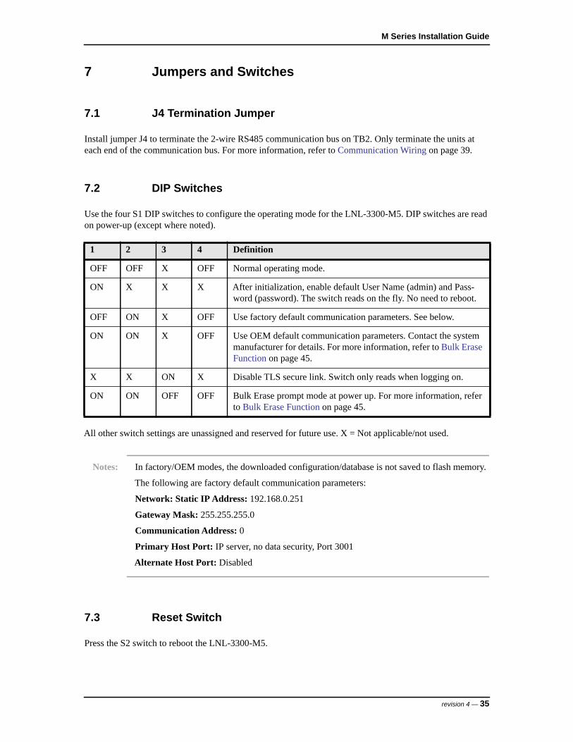
7.2 DIP Switches
Use the four S1 DIP switches to configure the operating mode for the LNL-3300-M5. DIP switches are read on power-up (except where noted).
All other switch settings are unassigned and reserved for future use. X = Not applicable/not used.
Notes: In factory/OEM modes, the downloaded configuration/database is not saved to flash memory.
The following are factory default communication parameters:
Network: Static IP Address: 192.168.0.251
Gateway Mask: 255.255.255.0
Communication Address: 0
Primary Host Port: IP server, no data security, Port 3001
Alternate Host Port: Disabled
7.3 Reset Switch
Press the S2 switch to reboot the LNL-3300-M5.
1 2 3 4 Definition
OFF OFF X OFF Normal operating mode.
ON X X X After initialization, enable default User Name (admin) and Pass-word (password). The switch reads on the fly. No need to reboot.
OFF ON X OFF Use factory default communication parameters. See below.
ON ON X OFF Use OEM default communication parameters. Contact the system manufacturer for details. For more information, refer to Bulk Erase Function on page 45.
X X ON X Disable TLS secure link. Switch only reads when logging on.
ON ON OFF OFF Bulk Erase prompt mode at power up. For more information, refer to Bulk Erase Function on page 45.
revision 4 — 35
LNL-3300-M5 Intelligent System Controller
8 Dual NIC Operation
Unless otherwise stated, use the following information to configure the LNL-3300-M5 for dual network card interface (NIC) operation.
8.1 LNL-ETHLAN-MICR (Micro Serial Server)
The ETHLAN-LITE/ETHLAN-MICR device plugs directly onto the LNL-3300-M5 panel and provides the ability to configure the controller for dual NIC operation.
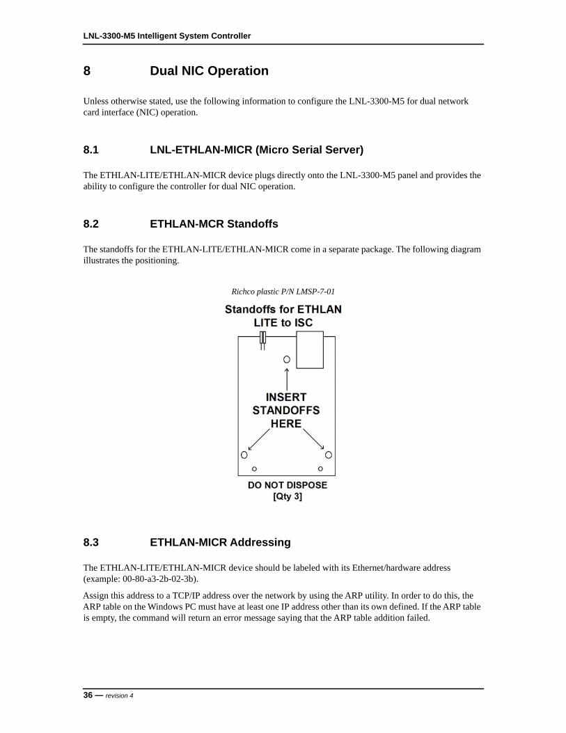
8.2 ETHLAN-MCR Standoffs
The standoffs for the ETHLAN-LITE/ETHLAN-MICR come in a separate package. The following diagram illustrates the positioning.
Richco plastic P/N LMSP-7-01
8.3 ETHLAN-MICR Addressing
The ETHLAN-LITE/ETHLAN-MICR device should be labeled with its Ethernet/hardware address (example: 00-80-a3-2b-02-3b).
Assign this address to a TCP/IP address over the network by using the ARP utility. In order to do this, the ARP table on the Windows PC must have at least one IP address other than its own defined. If the ARP table is empty, the command will return an error message saying that the ARP table addition failed.
36 — revision 4
M Series Installation Guide
Note: Using the ARP utility may require administrator rights.
To assign the Ethernet/hardware address using the ARP utility:
1. At the command prompt, type ARP-A to verify that there is at least one entry in the ARP table. If there is at least one entry, proceed to Step 3.
2. If there is no other entry listed in the ARP table besides the local machine, ping another IP machine on the network to build the ARP table. You must ping a host other than the machine on which you are working.
3. After the entry is listed in the ARP table, use the following command to ARP the IP address:arp -s <IP Address> <Ethernet/Hardware Address>
where the <IP address> is the numerical address (example: 192.168.002.203) and the <Ethernet/Hardware Address> is the address labeled on the Micro Serial Server device (example: 00-80-a3-2b-02-3b).
Note: The ARP/ping method only works during the first two minutes of LNL-ETHLAN-MICR operation. If this process is not completed in time, then the LNL-ETHLAN-MICR must be rebooted and the ARP/ping process redone.
4. Ping the IP address to have the device acknowledge the IP assignment. There should be replies from the IP address if the ARP command was accepted.
Note: The ETHLAN-MICR will not save this learned IP address permanently; this procedure is intended as a temporary measure to allow an administrator to Telnet into the LNL-ETHLAN-MICR for configuration. Once the power is recycled on the device, the IP programming that is done with the arp command will be lost.
After doing this, telnet into the IP address to complete the rest of the device configuration. For more information, refer to Establish Network Communication on page 38.
Important: In Establish Network Communication, it is critical to perform Step 3 (change ipaddress <your ip address>) in order to lock in the temporary IP address assigned by the ARP process. This step makes the IP address static within the device.
Note: BOOTP and RARP are disabled using commands when configuring the device for use. DHCP is disabled when the device is shipped from Lenel. However, if an NVR reset is performed on the device, DHCP, BOOTP, and RARP will all be re-enabled and if there is a DHCP server on the network the unit will obtain an IP address automatically and you will not be able to use the ARP command for programming. If there is no DHCP server on the network, the DHCP option
revision 4 — 37
LNL-3300-M5 Intelligent System Controller
within the device will be disabled again once a static IP address is successfully programmed into the device.
5. Remove all power from the LNL-3300-M5 for at least 15 seconds and then reapply power.
6. Use the access control software to define the LNL-3300-M5 as a LAN panel at the IP address that was assigned. The panel will come online.
8.4 Establish Network Communication
After a factory default reset, the following changes must be made:
1. At the prompt, type:set privileged and press <Enter>.
2. Type in the password:system and press <Enter>.
3. Determine and set the IP address. Type:change ipaddress [IP ADDRESS] and press <Enter>.
4. Set the Gateway. Type: change gateway [GATEWAY] and press <Enter>.
5. Set the boot flags. Type: change bootp disabled and press <Enter>change dhcp disabled and press <Enter>change rarp disabled and press <Enter>
6. Set the access type to remote. Type:change access remote and press <Enter>
7. At the prompt, type:logout and press <Enter>.
8. Exit from HyperTerminal and cycle power to the device.
38 — revision 4
M Series Installation Guide
9 Wiring
9.1 Communication Wiring
The LNL-3300-M5 communicates to the host via: on-board Ethernet 10-BaseT/100Base-TX port and/or the optional Lantronix Ethernet 10-BaseT/100Base-TX Micro125 interface.
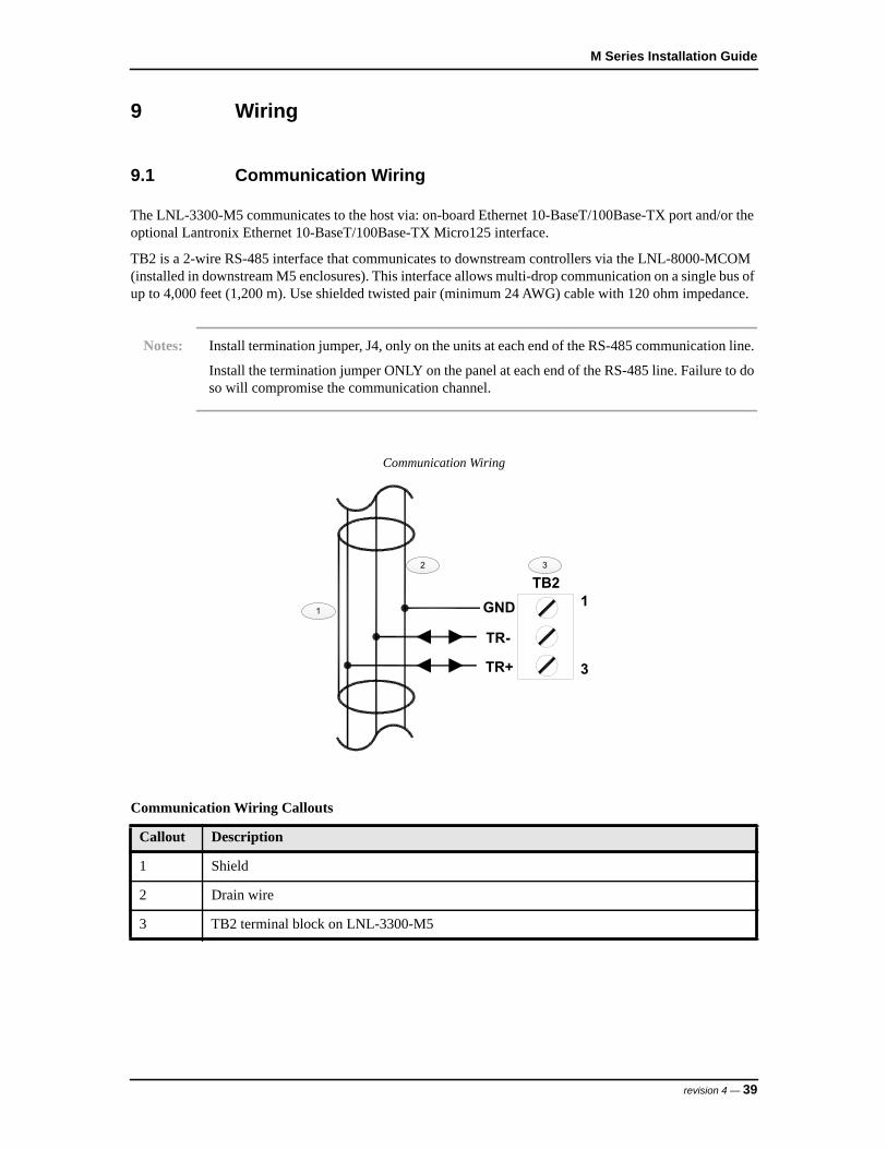
TB2 is a 2-wire RS-485 interface that communicates to downstream controllers via the LNL-8000-MCOM (installed in downstream M5 enclosures). This interface allows multi-drop communication on a single bus of up to 4,000 feet (1,200 m). Use shielded twisted pair (minimum 24 AWG) cable with 120 ohm impedance.
Notes: Install termination jumper, J4, only on the units at each end of the RS-485 communication line.
Install the termination jumper ONLY on the panel at each end of the RS-485 line. Failure to do so will compromise the communication channel.
Communication Wiring
Communication Wiring Callouts
Callout Description
1 Shield
2 Drain wire
3 TB2 terminal block on LNL-3300-M5
1
2 3
TB2GND
TR-
TR+
1
3
revision 4 — 39

LNL-3300-M5 Intelligent System Controller
9.2 Input Power, Enclosure Tamper, and Power Fault Input Wiring
The LNL-3300-M5 requires 12 VDC power, 3 A minimum. Depending on system configuration, a larger power supply may be required.
There are three pairs of connections for power, all are in parallel. If needed, the other two pairs can supply power to other I/O boards.
Connect the incoming +12 VDC power to TB1-3, and ground (12 VDC return) to TB1-4. Locate power source as close to the unit as possible. Connect power with minimum 18 gauge wire.
Input Power, Enclosure Tamper, and Power Fault Input Wiring
Notes: Connect the GND signal to earth ground in one location within the system. Multiple earth ground connections can cause ground loop problems and are not recommended.
Observe polarity on 12 VDC input.
There are two dedicated inputs for cabinet tamper (TMPR) and UPS fault monitoring (PFLT). Normal (safe) condition is a closed contact. If these inputs are not used, install a jumper wire.
Figure Input Power, Enclosure Tamper, and Power Fault Input Wiring Callouts
Callout Description
1 12 VDC power supply; 3 A minimum
2 TB1 terminal block on LNL-3300-M5
3 +12 VDC input power connection
4 Ground (12 VEC return) connection
5 Enclosure tamper and power fault input wiring connections
1
2
3
4
5
GND
VIN
TB1VIN 1
GND
GND
VIN
PFLT
TMPR
+
-
8
3
4
40 — revision 4
M Series Installation Guide
10 Configuration
To configure the LNL-3300-M5 ISC, use the embedded web configuration page to complete basic configuration, such as:
• Communication address• Connection type• Data security• Port number• User accounts
For more advanced configuration options, use a host application, such as the OnGuard software.
10.1 Web Configuration
10.1.1 Logging in for the First TimeThere is one pre-defined default user available on the LNL-3300-M5. To enable the default user, place DIP switch SW1 in the ON position after power-up. For more information, refer to DIP Switches on page 35.
Since there are no other users defined yet when logging on for the first time, use the default user name (admin) and password (password) to configure the ISC.
Notes: After configuring the LNL-3300-M5 using the web interface, make sure to place DIP switch SW1 in the OFF position to enable the settings made.
All boards have a static certificate that reflects a static IP address. This causes a warning to initially appear when trying to log in that states a problem with this website’s security certificate. Although it is not recommended, proceed to the website.
10.1.2 Configuration via Web PageThe configuration web page can be launched in one of two ways:
• From within System Administration (only if an IP address or host name is specified).• By using a browser to access the programmed IP address.
Depending on proxy settings, the configuration web page may need to be allowed. For more information, consult the browser’s online help or system administrator.
To configure the LNL-33300-M5 via the web page:
1. In System Administration, open Access Folders and select the LNL-3300-M5 tab.
2. Click [Configuration Web Page].The configuration web page launches in a browser.
You may also access the configuration web page by going to the device IP address from within the browser.
3. Click the link to the Login page. Log in using your user name and password.If DIP switch SW1 is in the ON position, use the default user name and password:
- Default user name: admin
revision 4 — 41

LNL-3300-M5 Intelligent System Controller
- Default password: passwordIf DIP switch SW1 is in the OFF position, use the login that was programmed in the device.
Click [Login].
4. The Home page indicates the type of device and has a Notes field. Enter a description here and click [Save Notes].
5. To configure network settings, click [Network].• If you are using DHCP, specify a host name.
By default, the host name consists of “MAC” followed by the numbers of the device MAC address. With DHCP, IP settings will be automatically configured.
• For a static IP address, specify the IP address, subnet mask, and default gateway.
6. Click [Accept].
7. To configure the host, click [Host Comm].a. Specify the controller’s communication address. This is the address used for RS-485, also must
match the setting in the access control software, even for IP communications.b. Configure the following:
– Connection Type: Choose from IP Server, Serial-RS232, Serial-modem, Serial-RS485 (LNL-3300-M5 only) and Serial-Cobox (LNL-3300-M5 only). Currently, the IP Client connection type is not supported.
– Data Security: The controller is capable of Password/AES encryption.– Port Number (default 3001): Must match setting in the access control software.
When using an IP Server connection, the controller may be configured to allow all IP addresses or only authorized IP addresses.
c. Configure an alternate host port if needed. Dual path communication is available on the LNL-3300-M5 only. If you opt not to use dual path communication, set this option to Disabled.
d. Click [Accept].
8. To view information, click [Device Info].You may view the time and product ID, as well as properties that have been configured, such as firmware version, serial number, device name, DIP switches, etc.
9. To configure user accounts, click [Users].User accounts may be created, edited, or deleted. Each user account has an associated user name and password, as well as a level and notes.
a. One of three different levels may be assigned to users. Level 1 provides full control. For Levels 2 and 3, refer to the following table.
Access View allowed Edit allowed
Home page Level 2: Yes (cannot edit notes)Level 3: Yes (cannot edit notes)
Level 2: NoLevel 3: No
Network page Level 2: YesLevel 3: No
Level 2: NoLevel 3: No
Host Port page Level 2: YesLevel 3: No
Level 2: NoLevel 3: No
Device Info page Level 2: YesLevel 3: Yes
N/A
42 — revision 4

M Series Installation Guide
For pages that cannot be viewed, the message is displayed when users attempt to access the page: “This page is unavailable due to one of the following reasons: your user level is not authorized to view this page, or another level 1 user is logged in at this time.”
b. Select the password strength.– Low: The minimum password length must be six characters. None of the password strength
criteria will be enforced.– Medium: The minimum password length must be six characters. Two of the password strength
criteria must be met.– High: The minimum password length is eight characters. Three of the password strength
criteria must be met. Additionally, strong passwords are checked to make sure that they are not based on the user name.
Password strength criteria:– Uppercase alphabet characters– Lowercase alphabet characters– Arabic numerals (0-9)– Non alphanumeric characters ` ! ? $ ^ * ( ) _ - + = { [ } ] : ; @ ~ # | < , > . ? /
Characters " , \, &, = and % are invalid characters and cannot be used for passwords.c. Specify the Session Timer (5 to 60 minutes). Click [Save].d. You may disable the web server by selecting the check box. When this option is selected and DIP
switch SW1 is off, all ports except for the host communication port are disabled. The configuration web page cannot be used to access the device.
e. Select the Enable door forced open filter check box if you do not want a forced open alarm if the door is opened within three seconds of it being closed.
10. For configuration of auto-save, click [Auto-Save].a. On this page, you may restore the last save or clear all the settings.b. Choose to disable or enable Auto-Save.
If Auto-Save is enabled, volatile memory is written to flash. The frequency of this action is specified in the timer (30 seconds to 30 minutes). Click [Save Settings].
11. You may click [Restore/Default] if you need to reload the factory settings or the current operating settings.
12. When you have completed configuring the device, click [Apply Settings], [Apply Settings, Reboot], and then [Log Out]. If the IP address has changed, you will need to log in with the new IP address to continue.
Users page Level 2: NoLevel 3: No
Level 2: NoLevel 3: No
Restore/Default page Level 2: NoLevel 3: No
Level 2: NoLevel 3: No
Apply Setting page Level 2: NoLevel 3: No
Level 2: NoLevel 3: No
Access View allowed Edit allowed
revision 4 — 43
LNL-3300-M5 Intelligent System Controller
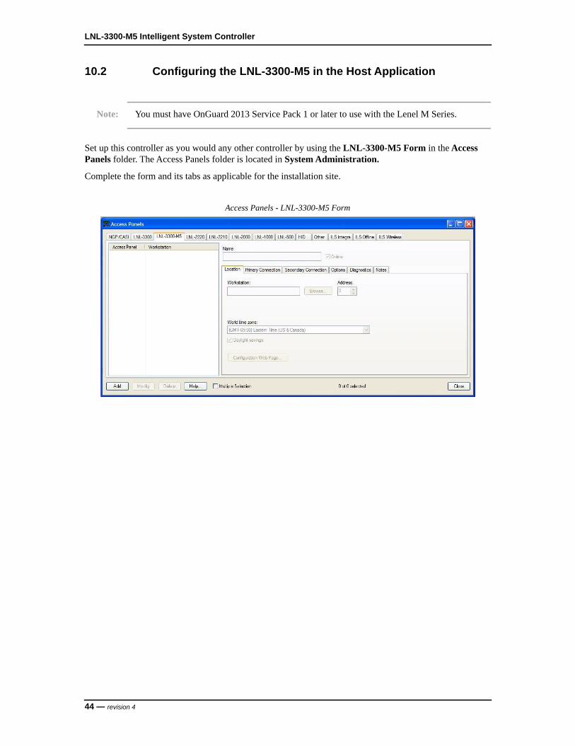
10.2 Configuring the LNL-3300-M5 in the Host Application
Note: You must have OnGuard 2013 Service Pack 1 or later to use with the Lenel M Series.
Set up this controller as you would any other controller by using the LNL-3300-M5 Form in the Access Panels folder. The Access Panels folder is located in System Administration.
Complete the form and its tabs as applicable for the installation site.
Access Panels - LNL-3300-M5 Form
44 — revision 4
M Series Installation Guide
11 Other Functions
11.1 Memory and Real Time Clock Backup Battery
A lithium backup battery powers the static RAM and the real time clock when input power is removed. This battery should be replaced annually.
The LNL-3300-M5 is typically shipped with an insulator installed between the battery holder and the battery. Remove the insulator from the battery holder after installation. Reinstall the insulator if the LNL-3300-M5 will be stored for a long period of time.
Use battery types BR2325, CR2325, BR2330, or CR2330.
Note: If data in the static RAM is determined to be corrupt after power up, all downloaded configuration database is considered invalid and is erased. All configuration data must be re-downloaded.
11.2 Bulk Erase Function
Use the bulk erase function to:
- Erase all configuration and cardholder database (sanitize board).- Update OEM default parameters after OEM code has been changed.- Recover from database corruption causing the LNL-3300-M5 to continuously reboot.
Note: If clearing the memory does not correct the initialization problem, contact Technical Support.
To use the bulk erase function:
1. Set the S1 DIP switches as follows:• 1 and 2 = ON• 3 and 4 = OFF
2. Apply power to the LNL-3300-M5.
3. Watch for LEDs 1 and 2, and 3 and 4 to alternately flash at a 0.5 second rate.
4. Within 10 seconds of powering up, change switches 1 or 2 to OFF. If these switches are not changed, the LNL-3300-M5 will power up using the OEM default communication parameters.
5. LED 2 flashes to indicate that the configuration memory is being erased. Full memory erase takes approximately 60 seconds.
6. When complete, only LEDs 1 and 4 flash for 8 seconds.
7. The LNL-3300-M5 reboots 8 seconds after LEDs 1 and 4 stop flashing (no LEDs are on during this time).
Do not remove power when performing this procedure.
revision 4 — 45

LNL-3300-M5 Intelligent System Controller
12 Status LEDs
• Power-up: All LEDs are OFF• Initialization:
- LED's 1 through 6 are sequenced during initialization.- LED's 1, 3, and 5 turn ON for approximately 1.5 seconds after the hardware initialization is
completed.- The application code then initializes. The length of initialization time depends on the size of
database (about 3 seconds without a card database). Each 10,000 cards adds about 3 seconds to the initialization.
- When LED's 1 through 4 flash at the same time, data is written to or read from flash memory.
Note: Do not cycle power while data is written to, or read from, the flash memory.
• Running: See the following table.
LED Description
1 Offline/online and battery status
Offline = 200 mS ON/800 mS OFF
Online = 800 mS ON/200 mS OFF
Double flash if battery is low
2 Host communication activity
3 Internal communication bus activity
4 TB2 communication activity (downstream enclosures)
5 Unassigned
6 Unassigned
YEL Onboard Ethernet speed:OFF = 10 Mb/sON = 100 Mb/s (yellow LED)
GRN OFF = no linkON = good link (green LED)Flashing = Ethernet activity
46 — revision 4
M Series Installation Guide
13 Specifications
The LNL-3300-M5 is intended for use in low voltage, Class 2 circuits only.
The following specifications are subject to change without notice.
• Primary Power: 12 VDC, ± 10 %, 330 mA maximum (does not include other I/O modules connected to the backplane)
• Memory and Clock Backup: 3 Volt Lithium, type BR2325, CR2325, BR2330, or CR2330• Host:
- Primary: Onboard 10-BaseT/100Base-TX Ethernet- Alternate: Optional 10-BaseT/100Base-TX using a Lantronix Micro125 Serial-to-Ethernet
interface daughter board, p/n MO11AA003-01R, or equivalent• Internal: Communication to M5 I/O boards: 9,600 to 115,200 bps, asynchronous• External:
- TB2: 2-wire RS-485 to downstream controller enclosures- 9600, 19200, 38400, or 115200 bps, asynchronous
• Inputs: Two (2) non-supervised, dedicated for cabinet tamper and power fault monitoring• Cable Requirements:
- Power: One (1) twisted pair, 18 AWG- RS-485: 24 AWG, 4,000 ft (1,200 m) maximum, shielded twisted pair, 120 ohm impedance- Ethernet: Cat 5 minimum- Alarm Input: One (1) twisted pair, 30 ohms maximum loop resistance
• Environmental:- Storage Temperature: -67 to +185°F (-55 to +85°C)- Operating Temperature: +32 to +158°F (0 to +70°C)- Humidity: 5 to 95% RHNC
• Mechanical:- Width: 4.56 in. (115.8 mm)- Length: 10.25 in. (260.4 mm)- Height: 0.8 in. (20.3 mm)- Weight (without connectors): 5.3 oz. (150 g) nominal
The following specifications apply to the LNL-3300-M5 with the Lantronix Serial-to-Ethernet Module:
• Mechanical:- Width: 4.56 in. (115.8 mm)- Length: 10.25 in. (260.4 mm)- Height: 1.27 in. (32.26 mm)- Weight (without connectors): 6.2 oz. (175 g) nominal
• Lantronix Serial-to-Ethernet Module Support:- Standoff size: Diameter 125 inch x 7/16 inch long- Supplier: Richco, Inc. part number LMSP-7-01, 3 pieces (not supplied)
revision 4 — 47

LNL-3300-M5 Intelligent System Controller
48 — revision 4

LNL-1100-20DI INPUT CONTROL MODULE


M Series Installation Guide
14 Overview of the LNL-1100-20DI
The LNL-1100-20DI is an Input Control Module that provides sensor monitoring via twenty (20) digital inputs that can be configured to support unsupervised or supervised alarm input circuits.
The LNL-1100-20DI includes two (2) processors, each monitoring ten input circuits. The first processor (A) monitors inputs 1IN through 10IN. The second processor (B) monitors inputs 11IN through 20IN. This board occupies two consecutive addresses on the communication bus.
LNL-1100-20DI Input Control Module
LNL-1100-20DI Input Control Module Callouts
Callout Description
1 Status LEDs
2 J1: to backplane in enclosure card cage
3 S1 DIP switches
4
5 1
2
3
ON
S1
12345678
A1
A2
A3
A4
B3
B4
B2
B1
4IN
4IN
3IN
3IN
2IN
2IN
1IN
1IN
TB1
5IN
5IN
110
1TB
210
1TB
310
1TB
410
10IN
8IN
9IN
10IN
9IN
8IN
7IN
7IN
6IN
6IN
15IN
13IN
14IN
15IN
14IN
13IN
12IN
12IN
11IN
11IN
20IN
20IN
17IN
18IN
19IN
19IN
18IN
17IN
16IN
16IN
revision 4 — 51

LNL-1100-20DI Input Control Module
4 Inputs monitored by Processor BCommunication address defined by S1 incremented by one
5 Inputs monitored by Processor ACommunication address defined by S1
LNL-1100-20DI Input Control Module Callouts
Callout Description
52 — revision 4
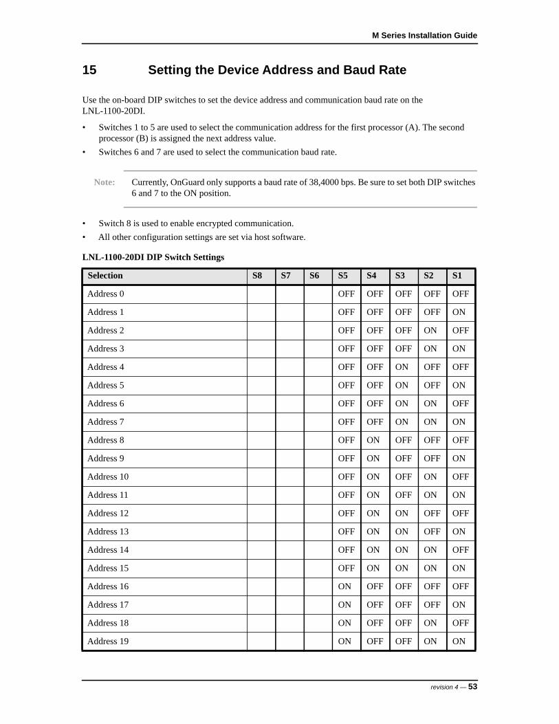
M Series Installation Guide
15 Setting the Device Address and Baud Rate
Use the on-board DIP switches to set the device address and communication baud rate on the LNL-1100-20DI.
• Switches 1 to 5 are used to select the communication address for the first processor (A). The second processor (B) is assigned the next address value.
• Switches 6 and 7 are used to select the communication baud rate.
Note: Currently, OnGuard only supports a baud rate of 38,4000 bps. Be sure to set both DIP switches 6 and 7 to the ON position.
• Switch 8 is used to enable encrypted communication.• All other configuration settings are set via host software.
LNL-1100-20DI DIP Switch Settings
Selection S8 S7 S6 S5 S4 S3 S2 S1
Address 0 OFF OFF OFF OFF OFF
Address 1 OFF OFF OFF OFF ON
Address 2 OFF OFF OFF ON OFF
Address 3 OFF OFF OFF ON ON
Address 4 OFF OFF ON OFF OFF
Address 5 OFF OFF ON OFF ON
Address 6 OFF OFF ON ON OFF
Address 7 OFF OFF ON ON ON
Address 8 OFF ON OFF OFF OFF
Address 9 OFF ON OFF OFF ON
Address 10 OFF ON OFF ON OFF
Address 11 OFF ON OFF ON ON
Address 12 OFF ON ON OFF OFF
Address 13 OFF ON ON OFF ON
Address 14 OFF ON ON ON OFF
Address 15 OFF ON ON ON ON
Address 16 ON OFF OFF OFF OFF
Address 17 ON OFF OFF OFF ON
Address 18 ON OFF OFF ON OFF
Address 19 ON OFF OFF ON ON
revision 4 — 53
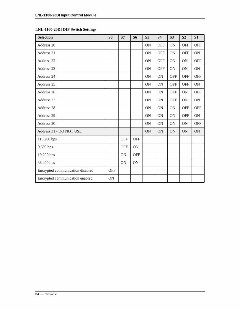
LNL-1100-20DI Input Control Module
Address 20 ON OFF ON OFF OFF
Address 21 ON OFF ON OFF ON
Address 22 ON OFF ON ON OFF
Address 23 ON OFF ON ON ON
Address 24 ON ON OFF OFF OFF
Address 25 ON ON OFF OFF ON
Address 26 ON ON OFF ON OFF
Address 27 ON ON OFF ON ON
Address 28 ON ON ON OFF OFF
Address 29 ON ON ON OFF ON
Address 30 ON ON ON ON OFF
Address 31 - DO NOT USE ON ON ON ON ON
115,200 bps OFF OFF
9,600 bps OFF ON
19,200 bps ON OFF
38,400 bps ON ON
Encrypted communication disabled OFF
Encrypted communication enabled ON
LNL-1100-20DI DIP Switch Settings
Selection S8 S7 S6 S5 S4 S3 S2 S1
54 — revision 4
M Series Installation Guide
16 Alarm Input Wiring
Typically, these inputs are used to monitor door position, request to exit, or alarm contacts. Input circuits can be configured as unsupervised or supervised. When unsupervised, reporting consists of only the open or closed states.
When an input circuit is configured for supervision, the LNL-1100-20DI also monitors the following abnormal circuit conditions:
• open circuit,• shorted circuit,• grounding of either side of the circuit*• the introduction of a foreign voltage*
* Grounded and foreign voltage states are not UL 294 required and therefore not verified by UL.
A supervised input circuit requires adding two resistors to the circuit to facilitate proper reporting. The standard supervised circuit requires 1K Ohm, 1% resistors and should be located as close to the sensor as possible. Custom end of line (EOL) resistances may be configured via the host software.
The input circuit wiring configurations shown are supported, but may not be typical.
revision 4 — 55
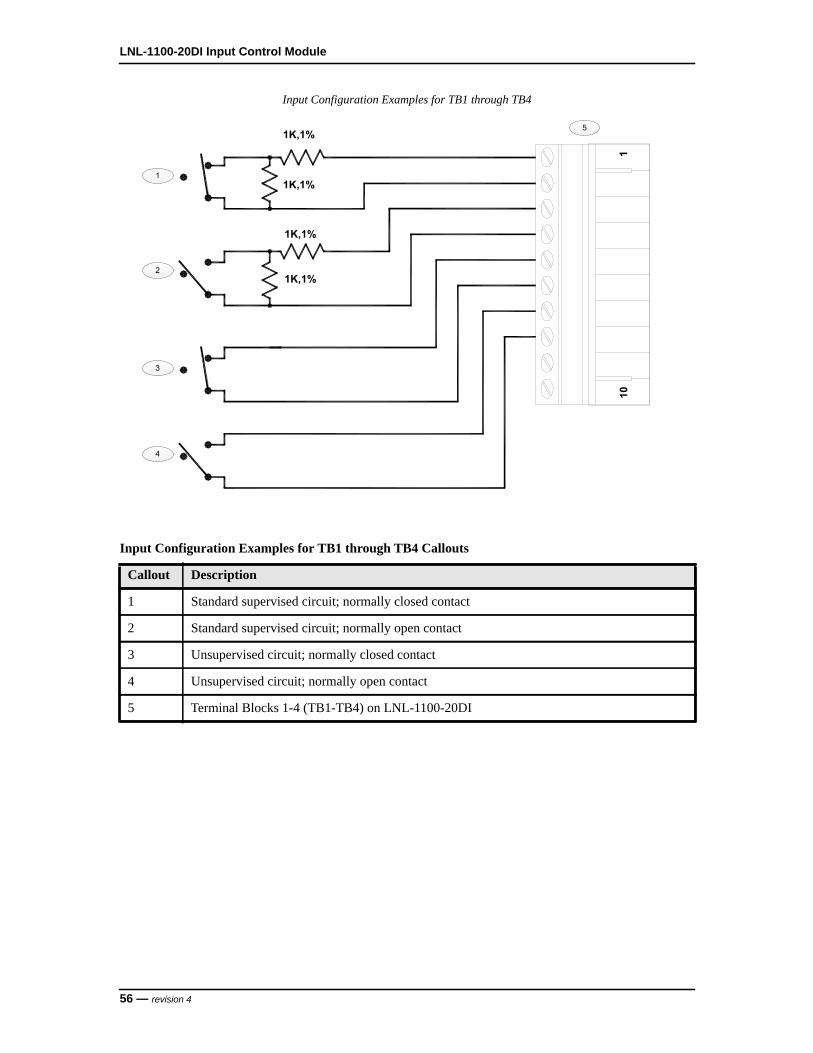
LNL-1100-20DI Input Control Module
Input Configuration Examples for TB1 through TB4
Input Configuration Examples for TB1 through TB4 Callouts
Callout Description
1 Standard supervised circuit; normally closed contact
2 Standard supervised circuit; normally open contact
3 Unsupervised circuit; normally closed contact
4 Unsupervised circuit; normally open contact
5 Terminal Blocks 1-4 (TB1-TB4) on LNL-1100-20DI
1
2
3
4
1K,1%
1K,1%
1K,1%
1K,1%
5
110
56 — revision 4

M Series Installation Guide
17 Status LEDs
• Power-up: All LEDs are OFF- Initialization: After power is applied, the board initializes- Initialization complete: LEDs 1-4 briefly turn ON then OFF- Run time: See the following descriptions for LEDs A1-A4 and B1-B4.
• LED A1/B1: Heartbeat and online status:- Offline: 1 second cycle, 200 mS ON/800 mS OFF- Online (non-encrypted communication): Flash cycle of 800 mS ON/200 mS OFF- Online (encrypted communication): 4 flash cycles of 700 mS ON/300 mS OFF- Error indication: Waiting for firmware to download; flash cycle of 100 mS ON/100 mS OFF
• LED A2/B2: SIO communication port status; indicates activity on the communication port• LED A3B3: OFF, not defined, for future use• LED A4/B4: OFF, not defined, for future use
revision 4 — 57
LNL-1100-20DI Input Control Module
18 Specifications
The LNL-1100-20DI is intended for use in low voltage, Class 2 circuits only.
The following specifications are subject to change without notice.• Primary Power: From the LNL-3300-M5; 12 VDC, ± 10 %, 165 mA maximum• Inputs: 20 unsupervised/supervised; Standard EOL: 1K/1K ohm, 1%, 1/4 watt• Communication: 9600, 19200, 38400, or 115200 bps, asynchronous• Alarm Input Cable Requirements: 1 twisted pair per input, 22 AWG shielded. 30 ohms maximum
loop resistance• Environmental:
- Storage Temperature: -67 to +185°F (-55 to +85°C)- Operating Temperature: +32 to +158°F (0 to +70°C)- Humidity: 5 to 95% RHNC
• Mechanical:- Width: 3.5 in. (88.9 mm) - Length: 10.25 in. (260.4 mm)- Height: 0.69 in. (17.5 mm)- Weight (without connectors): 4 oz (113 g) nominal
58 — revision 4

LNL-1200-16DO OUTPUT CONTROL MODULE

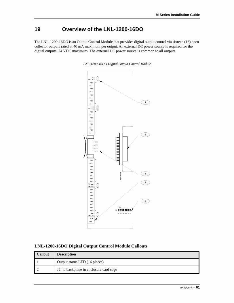
M Series Installation Guide
19 Overview of the LNL-1200-16DO
The LNL-1200-16DO is an Output Control Module that provides digital output control via sixteen (16) open collector outputs rated at 40 mA maximum per output. An external DC power source is required for the digital outputs, 24 VDC maximum. The external DC power source is common to all outputs.
LNL-1200-16DO Digital Output Control Module
LNL-1200-16DO Digital Output Control Module Callouts
Callout Description
1 Output status LED (16 places)
2 J2: to backplane in enclosure card cage
1
2
3
4
5
87
ON
S1
21 53 4 6
32
14
+VDC
DO-1
+VDC
DO-2
+VDC
DO-3
+VDC
DO-4
DO-8
DO-7
+VDC
+VDC
DO-6
+VDC
DO-5
+VDC
DO-12
DO-11
+VDC
+VDC
DO-10
+VDC
DO-9
+VDC
DO-16
DO-15
+VDC
+VDC
DO-14
+VDC
DO-13
+VDC
DC IN
GND
1
TB1
88
18
18
1
TB2
TB3
TB5
D9
D7
D10
D8
D11
D13
D12
D14
D15
D17
D17
D16
TB4
D5
D19D20
D6
revision 4 — 61

LNL-1200-16DO Output Control Module
3 Status LEDs
4 External power source (24 VDC maximum)
5 DIP switches
LNL-1200-16DO Digital Output Control Module Callouts
Callout Description
62 — revision 4

M Series Installation Guide
20 Setting the Device Address and Baud Rate
Use the on-board DIP switches to set the device address and communication baud rate on the LNL-1200-16DO.
• Switches 1 to 5 select the device address.• Switches 6 and 7 select the communication baud rate.
Note: Currently, OnGuard only supports a baud rate of 38,4000 bps. Be sure to set both DIP Switches 6 and 7 to the ON position.
• Switch 8 enables encrypted communication.
All other configuration settings are set in the host software.
DIP Switch Settings for the LNL-1200-16DO
Selection S1 S2 S3 S4 S5 S6 S7 S8
Address 0 OFF OFF OFF OFF OFF
Address 1 ON OFF OFF OFF OFF
Address 2 OFF ON OFF OFF OFF
Address 3 ON ON OFF OFF OFF
Address 4 OFF OFF ON OFF OFF
Address 5 ON OFF ON OFF OFF
Address 6 OFF ON ON OFF OFF
Address 7 ON ON ON OFF OFF
Address 8 OFF OFF OFF ON OFF
Address 9 ON OFF OFF ON OFF
Address 10 OFF ON OFF ON OFF
Address 11 ON ON OFF ON OFF
Address 12 OFF OFF ON ON OFF
Address 13 ON OFF ON ON OFF
Address 14 OFF ON ON ON OFF
Address 15 ON ON ON ON OFF
Address 16 OFF OFF OFF OFF ON
Address 17 ON OFF OFF OFF ON
Address 18 OFF ON OFF OFF ON
Address 19 ON ON OFF OFF ON
revision 4 — 63

LNL-1200-16DO Output Control Module
Address 20 OFF OFF ON OFF ON
Address 21 ON OFF ON OFF ON
Address 22 OFF ON ON OFF ON
Address 23 ON ON ON OFF ON
Address 24 OFF OFF OFF ON ON
Address 25 ON OFF OFF ON ON
Address 26 OFF ON OFF ON ON
Address 27 ON ON OFF ON ON
Address 28 OFF OFF ON ON ON
Address 29 ON OFF ON ON ON
Address 30 OFF ON ON ON ON
Address 31 ON ON ON ON ON
115,200 bps OFF OFF
119,600 bps ON OFF
19,200 bps OFF ON
38,400 bps ON ON
Encrypted communication disabled OFF
Encrypted communication enabled ON
DIP Switch Settings for the LNL-1200-16DO
Selection S1 S2 S3 S4 S5 S6 S7 S8
64 — revision 4
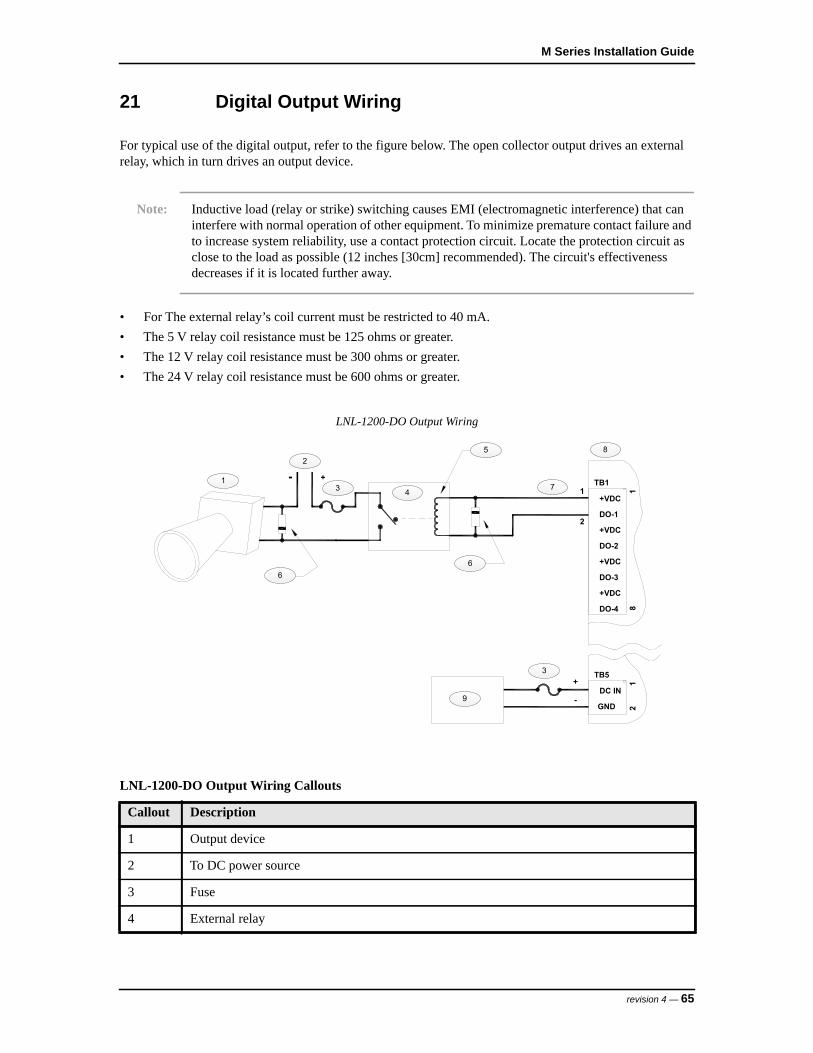
M Series Installation Guide
21 Digital Output Wiring
For typical use of the digital output, refer to the figure below. The open collector output drives an external relay, which in turn drives an output device.
Note: Inductive load (relay or strike) switching causes EMI (electromagnetic interference) that can interfere with normal operation of other equipment. To minimize premature contact failure and to increase system reliability, use a contact protection circuit. Locate the protection circuit as close to the load as possible (12 inches [30cm] recommended). The circuit's effectiveness decreases if it is located further away.
• For The external relay’s coil current must be restricted to 40 mA.• The 5 V relay coil resistance must be 125 ohms or greater.• The 12 V relay coil resistance must be 300 ohms or greater.• The 24 V relay coil resistance must be 600 ohms or greater.
LNL-1200-DO Output Wiring
LNL-1200-DO Output Wiring Callouts
Callout Description
1 Output device
2 To DC power source
3 Fuse
4 External relay
1
2
4
5
66
73
3
8
9
DO-1
+VDC
+VDC
+VDC
+VDC
DO-3
DO-2
DO-4 811
2
TB1
1
GND
DC IN
TB5
2
+
+
-
revision 4 — 65
LNL-1200-16DO Output Control Module
Suppression Diode Selection Notes:
- Diode current rating: > 1x strike current- Diode break down voltage: 4x strike voltage- 12 VDC or 24 VDC strike, use diode 1N4002 (100 V / 1A) typical
5 Coil resistance (125 ohm minimum)
6 Suppression diode (see Suppression Diode Selection Notes below)
7 +5 to +24 VDC; 40 mA maximum
8 TB1 and TB5 terminal blocks on LNL-1200-16DO
9 Digital output power source (+5 to +24 VDC)
LNL-1200-DO Output Wiring Callouts
Callout Description
66 — revision 4
M Series Installation Guide
22 Status LEDs
• Power-up: All LEDs are OFF- Initialization: After power is applied, the board initializes- Initialization complete: LEDs 1-4 briefly turn ON then OFF- Run time: See the following descriptions for LEDs 1-4
• LED 1: Heartbeat and online status:- Offline: 1 second cycle, 200 mS ON/800 mS OFF- Online (non-encrypted communication): Flash cycle of 800 mS ON/200 mS OFF- Online (encrypted communication): 4 flash cycles of 700 mS ON/300 mS OFF- Error indication: Waiting for firmware to download; flash cycle of 100 mS ON/100 mS OFF
• LED 2: SIO communication port status; indicates activity on the communication port• LED 3: OFF, not defined, for future use• LED 4: OFF, not defined, for future use
revision 4 — 67
LNL-1200-16DO Output Control Module
23 Specifications
The LNL-1200-16DO is intended for use in low voltage, Class 2 circuits only.
The following specifications are subject to change without notice.• Primary Power (from LNL-3300-M5): 12 VDC, ± 10 %, 30 mA maximum• Power for Digital Outputs: 24 VDC maximum, 640 mA maximum• Communication: 9600, 19200, 38400, or 115200 bps, asynchronous• Output Cable Requirements: As required for the load• Environmental:
- Storage Temperature: -67 to +185°F (-55 to +85°C)- Operating Temperature: +32 to +158°F (0 to +70°C- Humidity: 5 to 95% RHNC
• Mechanical:- Width: 3.5 in. (88.9 mm)- Length: 10.25 in. (260.4 mm)- Height: 0.69 in. (17.5 mm)- Weight (without connectors): 3.7 oz. (105 g) nominal
68 — revision 4

LNL-1200-16DOR OUTPUT CONTROL MODULE


M Series Installation Guide
24 Overview of the LNL-1200-16DOR
The LNL-1200-16DO is an Output Control Module that provides digital output control via sixteen (16) open collector outputs rated at 40 mA maximum per output. An external DC power source is required for the digital outputs, 24 VDC maximum. The external DC power source is common to all outputs.
LNL-1200-16DOR Relay Output Control Module
LNL-1200-16DOR Relay Output Control Module Callouts
Callout Description
1 J6: to backplane in enclosure card cage
2 Status LEDs
43
21
TB3
1
K1
87
ON
S1
21 53 4 6
K2
K3
K4
K5
K6
K7
K8
K9
K10
K11
K12
K13
K14
K15
K16
TB2
11
1TB
1TB
4
C
C
NO
K3
NO
C
K2
NC
NO
C
NC
K1
NO
K4
NO
C
NO
C
NC
NC
NO
C
C
NO
K8
K7
K5
K6
NO
C
NO
C
NC
NC
NO
C
C
NO
K11
K9
K10
NO
C
C
NO
NC
NC
C
NO
C
NO
K12
K13
K14
NO
NO
K15
K16
1010
1010
16D
OR
1
2
3
revision 4 — 71

LNL-1200 Output Control Module
3 DIP switches
LNL-1200-16DOR Relay Output Control Module Callouts
Callout Description
72 — revision 4
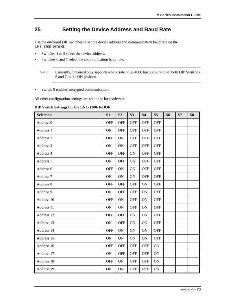
M Series Installation Guide
25 Setting the Device Address and Baud Rate
Use the on-board DIP switches to set the device address and communication baud rate on the LNL-1200-16DOR.
• Switches 1 to 5 select the device address.• Switches 6 and 7 select the communication baud rate.
Note: Currently, OnGuard only supports a baud rate of 38,4000 bps. Be sure to set both DIP Switches 6 and 7 to the ON position.
• Switch 8 enables encrypted communication.
All other configuration settings are set in the host software.
DIP Switch Settings for the LNL-1200-16DOR
Selection S1 S2 S3 S4 S5 S6 S7 S8
Address 0 OFF OFF OFF OFF OFF
Address 1 ON OFF OFF OFF OFF
Address 2 OFF ON OFF OFF OFF
Address 3 ON ON OFF OFF OFF
Address 4 OFF OFF ON OFF OFF
Address 5 ON OFF ON OFF OFF
Address 6 OFF ON ON OFF OFF
Address 7 ON ON ON OFF OFF
Address 8 OFF OFF OFF ON OFF
Address 9 ON OFF OFF ON OFF
Address 10 OFF ON OFF ON OFF
Address 11 ON ON OFF ON OFF
Address 12 OFF OFF ON ON OFF
Address 13 ON OFF ON ON OFF
Address 14 OFF ON ON ON OFF
Address 15 ON ON ON ON OFF
Address 16 OFF OFF OFF OFF ON
Address 17 ON OFF OFF OFF ON
Address 18 OFF ON OFF OFF ON
Address 19 ON ON OFF OFF ON
revision 4 — 73

LNL-1200 Output Control Module
Address 20 OFF OFF ON OFF ON
Address 21 ON OFF ON OFF ON
Address 22 OFF ON ON OFF ON
Address 23 ON ON ON OFF ON
Address 24 OFF OFF OFF ON ON
Address 25 ON OFF OFF ON ON
Address 26 OFF ON OFF ON ON
Address 27 ON ON OFF ON ON
Address 28 OFF OFF ON ON ON
Address 29 ON OFF ON ON ON
Address 30 OFF ON ON ON ON
Address 31 ON ON ON ON ON
115,200 bps OFF OFF
119,600 bps ON OFF
19,200 bps OFF ON
38,400 bps ON ON
Encrypted communication disabled OFF
Encrypted communication enabled ON
DIP Switch Settings for the LNL-1200-16DOR
Selection S1 S2 S3 S4 S5 S6 S7 S8
74 — revision 4

M Series Installation Guide
26 Relay Output Wiring
Eight (8) Form-C and eight Form-A contact relays control door lock mechanisms or alarm signaling devices. The relay contacts are rated at 2 A @ 30 VAC/DC, dry contact configuration.
When controlling power to the door strike, the Normally Open and Common poles are used. When momentarily removing power to unlock the door, as with a magnetic lock, the Normally Closed and Common poles are used. If the relay does not have a Normally Closed pole, the relay must be configured by the host to be energized when in the locked state. Check with local building codes for proper egress door installation.
Note: Excessive load switching causes contact wear and premature failure. Inductive load (strike) switching causes EMI (electromagnetic interference) which may interfere with normal operation of other equipment. To minimize premature contact failure and to increase system reliability, use a contact protection circuit. Locate the protection circuit as close to the load as possible [12 inches (30cm) recommended]. The circuit’s effectiveness decreases if it is located further away.
Use a sufficiently large gauge wire to avoid voltage loss on the load current.
LNL-1200-16DOR Relay Definitions
Relay Terminal Block Description
1 TB1-1TB1-2TB1-3
Normally Closed (NC)Common (C)Normally Open (NO)
2 TB1-4TB1-5TB1-6
Normally Closed (NC)Common (C)Normally Open (NO)
3 TB1-7TB1-8
Common (C)Normally Open (NO)
4 TB1-9TB1-10
Common (C)Normally Open (NO)
5 TB2-1TB2-2TB2-3
Normally Closed (NC)Common (C)Normally Open (NO)
6 TB2-4TB2-5TB2-6
Normally Closed (NC)Common (C)Normally Open (NO)
7 TB2-7TB2-8
Common (C)Normally Open (NO)
8 TB2-9TB2-10
Common (C)Normally Open (NO)
9 TB3-1TB3-2TB3-3
Normally Closed (NC)Common (C)Normally Open (NO)
revision 4 — 75

LNL-1200 Output Control Module
DC Door Strike Wiring
10 TB3-4TB3-5TB3-6
Normally Closed (NC)Common (C)Normally Open (NO)
11 TB3-7TB3-8
Common (C)Normally Open (NO)
12 TB3-9TB3-10
Common (C)Normally Open (NO)
13 TB4-1TB4-2TB4-3
Normally Closed (NC)Common (C)Normally Open (NO)
14 TB4-4TB4-5TB4-6
Normally Closed (NC)Common (C)Normally Open (NO)
15 TB4-7TB4-8
Common (C)Normally Open (NO)
16 TB4-9TB4-10
Common (C)Normally Open (NO)
DC Door Strike Wiring Callouts
Callout Description
1 DC strike
2 To DC power source
LNL-1200-16DOR Relay Definitions
Relay Terminal Block Description
1 2
3
4
5
NC
NO
C
NO 10
K4
C
NO
C
K3
K2
NO
C
NC
K1
TB1
76 — revision 4
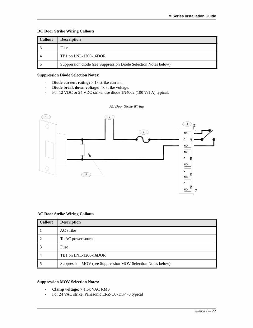
M Series Installation Guide
Suppression Diode Selection Notes:
- Diode current rating: > 1x strike current.- Diode break down voltage: 4x strike voltage.- For 12 VDC or 24 VDC strike, use diode 1N4002 (100 V/1 A) typical.
AC Door Strike Wiring
Suppression MOV Selection Notes:
- Clamp voltage: > 1.5x VAC RMS- For 24 VAC strike, Panasonic ERZ-C07DK470 typical
3 Fuse
4 TB1 on LNL-1200-16DOR
5 Suppression diode (see Suppression Diode Selection Notes below)
AC Door Strike Wiring Callouts
Callout Description
1 AC strike
2 To AC power source
3 Fuse
4 TB1 on LNL-1200-16DOR
5 Suppression MOV (see Suppression MOV Selection Notes below)
DC Door Strike Wiring Callouts
Callout Description
1 2
3
4
NO
NC
C
NO
NC
C
NO
NO
C
C
110
K4
K3
K2
K1
TB1
5
revision 4 — 77

LNL-1200 Output Control Module
27 Status LEDs
• Power-up: All LEDs are OFF- Initialization: After power is applied, the board initializes- Initialization complete: LEDs 1-4 briefly turn ON then OFF- Run time: See the following descriptions for LEDs 1-4
• LED 1: Heartbeat and online status:- Offline: 1 second cycle, 200 mS ON/800 mS OFF- Online (non-encrypted communication): Flash cycle of 800 mS ON/200 mS OFF- Online (encrypted communication): 4 flash cycles of 700 mS ON/300 mS OFF- Error indication: Waiting for firmware to download; flash cycle of 100 mS ON/100 mS OFF
• LED 2: SIO communication port status; indicates activity on the communication port• LED 3: OFF, not defined, for future use• LED 4: OFF, not defined, for future use
78 — revision 4
M Series Installation Guide
28 Specifications
The LNL-1200-16DOR is intended for use in low voltage, Class 2 circuits only.
The following specifications are subject to change without notice.• Primary Power (from LNL-3300-M5): 12 VDC, ± 10 %, 300 mA maximum• Power for Digital Outputs: 24 VDC maximum, 640 mA maximum• Relay Contacts:
- Eight (8) Form-C, 2 A @ 30 VAC/DC, resistive- Eight (8) Form-A, 2 A @ 30 VAC/DC, resistive
• Communication: 9600, 19200, 38400, or 115200 bps, asynchronous• Output Cable Requirements: As required for the load• Environmental:
- Storage Temperature: -67 to +185°F (-55 to +85°C)- Operating Temperature: +32 to +158°F (0 to +70°C- Humidity: 5 to 95% RHNC
• Mechanical:- Width: 3.5 in. (88.9 mm)- Length: 10.25 in. (260.4 mm)- Height: 0.69 in. (17.5 mm)- Weight (without connectors): 5 oz. (144 g) nominal
revision 4 — 79

LNL-1200 Output Control Module
80 — revision 4
LNL-1320-2RP DUAL DOOR CONTROL MODULE


M Series Installation Guide
29 Overview of the LNL-1320-2RP
The LNL-1320-2RP is a Dual Door Control Module that provides two (2) reader interface ports.
The LNL-1320-2RP accepts data from readers with Clock/Data, Wiegand, F/2F, supervised F/2F signaling and door hardware. The LNL-1320-2RP provides LED status, strike control and reader power of 5 VDC or 12 VDC.
Each of the two reader interface ports provides inputs for door position monitoring and request-to-exit (REX). The LNL-1320-2RP also has three Form-C relay outputs used for strike control, alarm contact shunting and auxiliary device control for each reader.
LNL-1320-2RP Dual Door Control Module
LNL-1320-2RP Dual Door Control Module Callouts
Callout Desscription
1 J5: Reader voltage selection jumper
2 J6: to backplane in enclosure card cage
1
2
3
4
5
6
24
31
TB2
TB3
J5+5V
+12V
K3
K2
K1
K4
K5
K6
TB4
TB1
S1
J621 3 4 76 85
ON
10VO
GND
DISP
LED
REX+
WD0
WD1DC+
NUDC-
REX-CLK DO
1
DC-
CLK DOREX-NU
DC+WD1
REX+
WD0
LED
DISP
GNDVO
101
11
99
NC
C
NO
C
NC
NO
C
NC
NO
K1
K2K3
C
NO
K6NC
K5
NO
NC
C
NO
K4C
NC
revision 4 — 83

LNL-1320-2RP Dual Door Control Module
3 Status LEDs
4 DIP switches
5 Reader Port 2
6 Reader Port 1
LNL-1320-2RP Dual Door Control Module Callouts
Callout Desscription
84 — revision 4
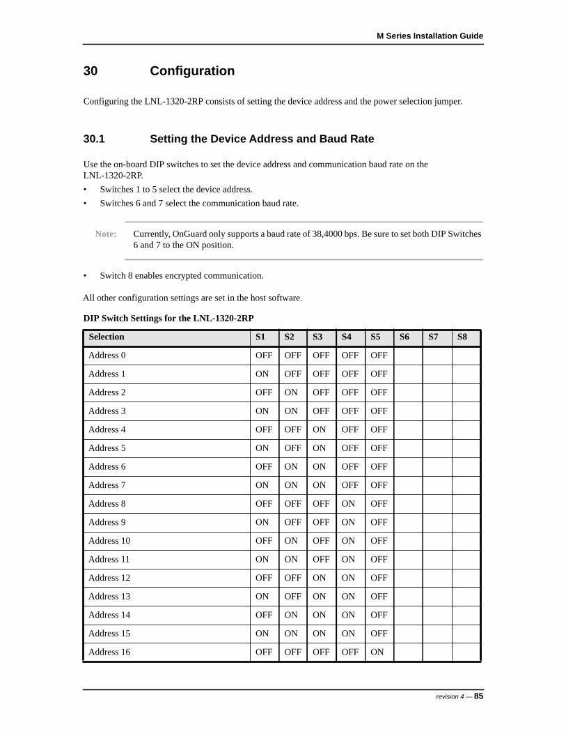
M Series Installation Guide
30 Configuration
Configuring the LNL-1320-2RP consists of setting the device address and the power selection jumper.
30.1 Setting the Device Address and Baud Rate
Use the on-board DIP switches to set the device address and communication baud rate on the LNL-1320-2RP.• Switches 1 to 5 select the device address.• Switches 6 and 7 select the communication baud rate.
Note: Currently, OnGuard only supports a baud rate of 38,4000 bps. Be sure to set both DIP Switches 6 and 7 to the ON position.
• Switch 8 enables encrypted communication.
All other configuration settings are set in the host software.
DIP Switch Settings for the LNL-1320-2RP
Selection S1 S2 S3 S4 S5 S6 S7 S8
Address 0 OFF OFF OFF OFF OFF
Address 1 ON OFF OFF OFF OFF
Address 2 OFF ON OFF OFF OFF
Address 3 ON ON OFF OFF OFF
Address 4 OFF OFF ON OFF OFF
Address 5 ON OFF ON OFF OFF
Address 6 OFF ON ON OFF OFF
Address 7 ON ON ON OFF OFF
Address 8 OFF OFF OFF ON OFF
Address 9 ON OFF OFF ON OFF
Address 10 OFF ON OFF ON OFF
Address 11 ON ON OFF ON OFF
Address 12 OFF OFF ON ON OFF
Address 13 ON OFF ON ON OFF
Address 14 OFF ON ON ON OFF
Address 15 ON ON ON ON OFF
Address 16 OFF OFF OFF OFF ON
revision 4 — 85
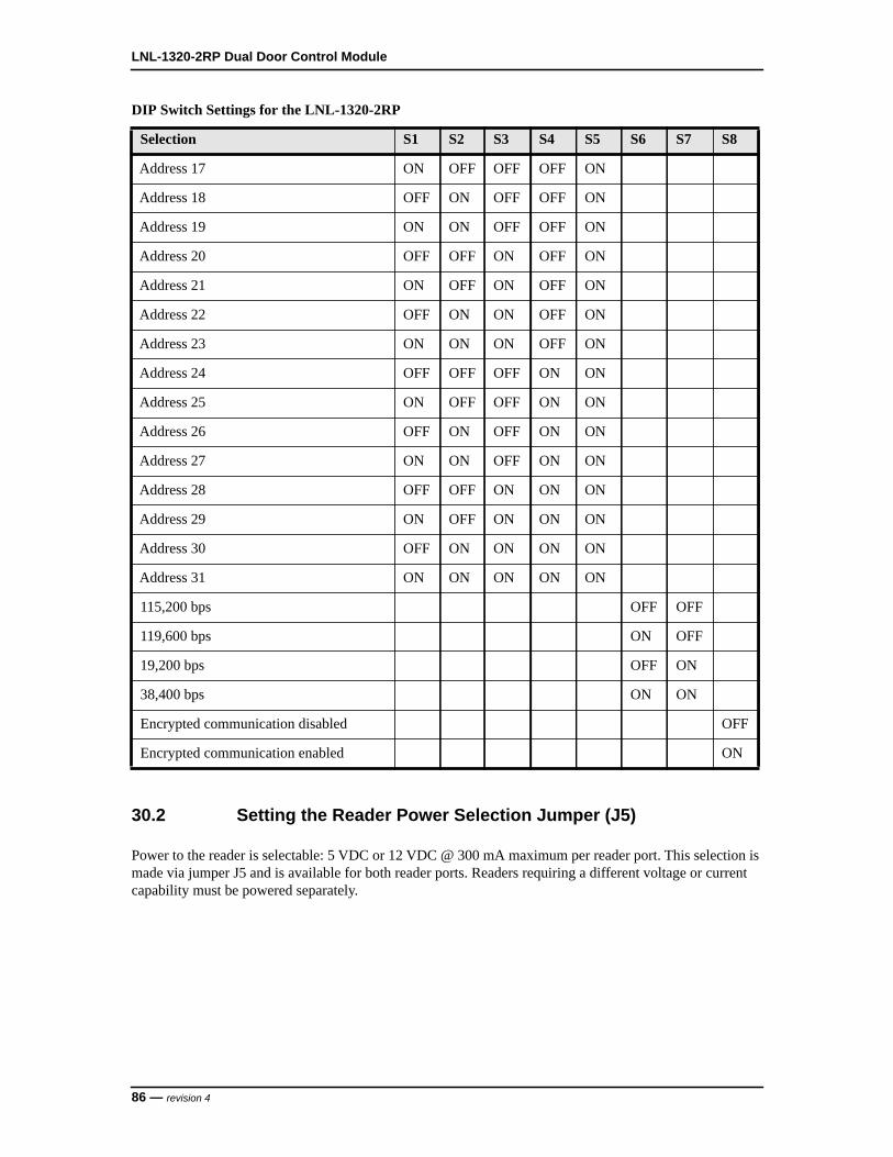
LNL-1320-2RP Dual Door Control Module
30.2 Setting the Reader Power Selection Jumper (J5)
Power to the reader is selectable: 5 VDC or 12 VDC @ 300 mA maximum per reader port. This selection is made via jumper J5 and is available for both reader ports. Readers requiring a different voltage or current capability must be powered separately.
Address 17 ON OFF OFF OFF ON
Address 18 OFF ON OFF OFF ON
Address 19 ON ON OFF OFF ON
Address 20 OFF OFF ON OFF ON
Address 21 ON OFF ON OFF ON
Address 22 OFF ON ON OFF ON
Address 23 ON ON ON OFF ON
Address 24 OFF OFF OFF ON ON
Address 25 ON OFF OFF ON ON
Address 26 OFF ON OFF ON ON
Address 27 ON ON OFF ON ON
Address 28 OFF OFF ON ON ON
Address 29 ON OFF ON ON ON
Address 30 OFF ON ON ON ON
Address 31 ON ON ON ON ON
115,200 bps OFF OFF
119,600 bps ON OFF
19,200 bps OFF ON
38,400 bps ON ON
Encrypted communication disabled OFF
Encrypted communication enabled ON
DIP Switch Settings for the LNL-1320-2RP
Selection S1 S2 S3 S4 S5 S6 S7 S8
86 — revision 4

M Series Installation Guide
J5 Reader Power Selection
J5 Reader Power Selection Callouts
Callout Description
1 5 VDC is available on both reader interface ports
2 12 VDC is available on both reader interface ports
+12V
+5V
1
2
revision 4 — 87

LNL-1320-2RP Dual Door Control Module
31 Reader Wiring
The reader ports on the LNL-1320-2RP support the following reader types:
• Clock/Data• Wiegand• F/2F• Supervised F/2F
The following are basic reader cable requirements. For more information, refer to Specifications on page 101.
• F/2F and supervised F/2F readers require a shielded 4-conductor cable. • Clock/Data and Wiegand readers require a shielded 5-conductor cable.
Reader port configuration is defined by the host software.
31.1 LNL-1320-2RP to Reader Wiring
Wiegand Reader
Wiegand Reader Callouts
Callout Description
1 Wiegand reader
2 TB1 or TB3 on LNL-1320-2RP
3 Terminal 1: +5 VDC/+12 VDC connection
4 Terminal 2: Ground connection
1 2
TB1
or TB3
REX-CLK DO
DC+
NUDC-
4
7
6 WD0
WD1
LED
REX+
1
2
VO
GND
DISP
101
3
5
7
4
6
88 — revision 4

M Series Installation Guide
Magnetic Reader
5 Terminal 4: Door DO (Reader LED) connection
6 Terminal 6: Data 0 connection
7 Terminal 7: Data 1 connection
Magnetic Reader Callouts
Callout Description
1 Magnetic reader
2 TB1 or TB3 on LNL-1320-2RP
3 Terminal 1: +5 VDC/+12 VDC connection
4 Terminal 2: Ground connection
5 Terminal 4: Door DO (Reader LED) connection
6 Terminal 6: Data connection
7 Terminal 7: Clock connection
Wiegand Reader Callouts
Callout Description
1 2
TB1
or TB3
REX-CLK DO
DC+
NUDC-
4
7
6 WD0
WD1
LED
REX+
1
2VO
GND
DISP
101
3
4
7
5
6
revision 4 — 89
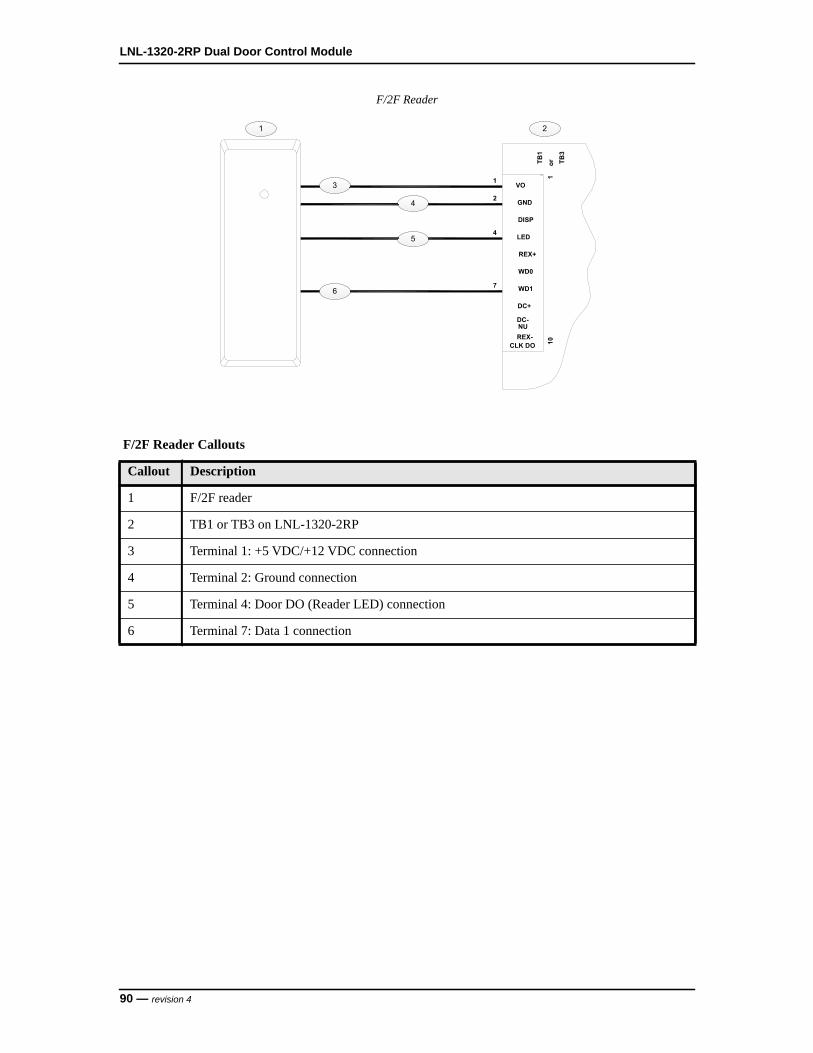
LNL-1320-2RP Dual Door Control Module
F/2F Reader
F/2F Reader Callouts
Callout Description
1 F/2F reader
2 TB1 or TB3 on LNL-1320-2RP
3 Terminal 1: +5 VDC/+12 VDC connection
4 Terminal 2: Ground connection
5 Terminal 4: Door DO (Reader LED) connection
6 Terminal 7: Data 1 connection
1 2
REX-CLK DO 10
WD0
WD1
DC+
DC-NU
7
DISP
REX+
4 LED
1VO
2 GND
TB1
or TB3
1
3
4
6
5
90 — revision 4

M Series Installation Guide
Supervised F/2F Reader
31.2 Door Position Monitor and REX Input Wiring
Typically, the door position monitor switch uses the Normally Closed (NC) contact and the REX uses the Normally Open (NO) contact.
For the LNL-1320-2RP, the door position monitor and REX switches can be wired in several different configurations.
These configurations are downloaded from the host and may be changed.
Supervised F/2F Reader Callouts
Callout Description
1 Supervised F/2F reader
2 TB1 or TB3 on LNL-1320-2RP
3 Terminal 1: +5 VDC/+12 VDC connection
4 Terminal 2: Ground connection
5 Terminal 3: Display DO connection
6 Terminal 4: Door DO (Reader LED) connection
7 Terminal 7: Data 1 connection
8 Wire jumper to Terminal 3 (Display DO)
1 2
REX+
WD1
WD0
DC-
CLK DOREX-
DC+
7
10
NU
GND
VO
DISP
LED
1
4
2
TB1
or TB3
1
3
3
4
5
6
8
7
revision 4 — 91

LNL-1320-2RP Dual Door Control Module
31.2.1 Unsupervised Inputs wired to the LNL-1320-2RP
Unsupervised inputs for the door position monitor and REX switches are wired to TB1 for the first reader, and TB3 for the second reader. End-of-Line (EOL) resistors are not required.
Unsupervised Input Wiring on LNL-1320-2RP
31.2.2 Unsupervised Inputs wired to the F/2F Reader
Unsupervised inputs for the door position monitor and REX switches are wired directly to the F/2F reader configured for 2-State Supervision. See the reader’s documentation for the proper connection terminals. End-Of-Line (EOL) resistors are not required.
Unsupervised Input Wiring on LNL-1320-2RP Callouts
Callout Description
1 TB1 or TB3 on LNL-1320-2RP
2 Normally Open contact for Request-to-Exit (REX) switch
3 Normally Closed contact for door monitor switch
1
2
3
GND
DISP
REX+
WD1
WD0
LED
CLK DOREX-
DC+
NUDC-
VO
101
TB1
or TB3
2
5
8
92 — revision 4

M Series Installation Guide
Unsupervised Input Wiring on F/2F Reader
31.2.3 Supervised Inputs wired to the F/2F Reader
Supervised inputs for the door position monitor and REX switches are wired directly to the F/2F reader configured for 4-State Supervision: open, closed, short, and cut. See the reader’s documentation for the proper connection terminals. EOL resistors typically require two 1K ohm resistors as shown in the figure below. Install the EOL resistors as close to the switch as possible.
Unsupervised Input Wiring on F/2F Reader Callouts
Callout Description
1 F/2F reader
2 To LNL-1320-2RP
3 +5 VDC/+12 VDC connection
4 Ground connection
5 Door DO (reader LED) connection
6 Data 1 connection
7 Normally Closed contact for door monitor switch
8 Normally Open contact for Request-to-Exit (REX) switch
1
2
3
4
5
6
7
8
revision 4 — 93

LNL-1320-2RP Dual Door Control Module
Supervised Input Wiring on F/2F Reader
31.3 Door Strike Wiring
There are two options for door strike wiring on the LNL-1320-2RP: internal relay and external relay.
Each relay option can be wired for AC or DC current.
31.3.1 Internal Relay Door Strike WiringEach reader port on the LNL-1320-2RP has three Form-C contact relays for controlling door strikes or other devices. Relay contact rating: 2 A @ 30 VAC/DC maximum.
Supervised Input Wiring on F/2F Reader Callouts
Callout Description
1 Supervised F/2F reader
2 To LNL-1320-2RP
3 +5 VDC/+12 VDC connection
4 Ground connection
5 Door DO (reader LED) connection
6 Data 1 connection
7 Normally Closed contact for door monitor switch
8 Normally Open contact for REX switch
1
2
7
8
1K,1%
1K,1%
1K,1%
1K,1%
3
4
5
6
94 — revision 4
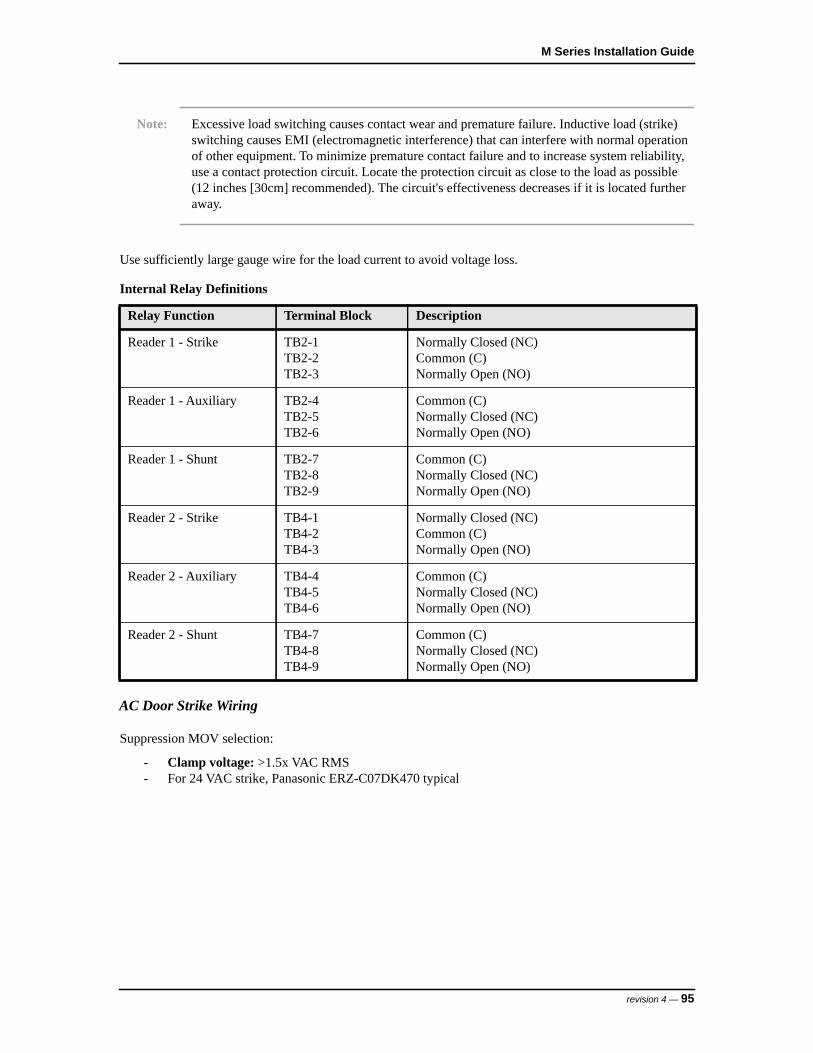
M Series Installation Guide
Note: Excessive load switching causes contact wear and premature failure. Inductive load (strike) switching causes EMI (electromagnetic interference) that can interfere with normal operation of other equipment. To minimize premature contact failure and to increase system reliability, use a contact protection circuit. Locate the protection circuit as close to the load as possible (12 inches [30cm] recommended). The circuit's effectiveness decreases if it is located further away.
Use sufficiently large gauge wire for the load current to avoid voltage loss.
AC Door Strike Wiring
Suppression MOV selection:
- Clamp voltage: >1.5x VAC RMS- For 24 VAC strike, Panasonic ERZ-C07DK470 typical
Internal Relay Definitions
Relay Function Terminal Block Description
Reader 1 - Strike TB2-1TB2-2TB2-3
Normally Closed (NC)Common (C)Normally Open (NO)
Reader 1 - Auxiliary TB2-4TB2-5TB2-6
Common (C)Normally Closed (NC)Normally Open (NO)
Reader 1 - Shunt TB2-7TB2-8TB2-9
Common (C)Normally Closed (NC)Normally Open (NO)
Reader 2 - Strike TB4-1TB4-2TB4-3
Normally Closed (NC)Common (C)Normally Open (NO)
Reader 2 - Auxiliary TB4-4TB4-5TB4-6
Common (C)Normally Closed (NC)Normally Open (NO)
Reader 2 - Shunt TB4-7TB4-8TB4-9
Common (C)Normally Closed (NC)Normally Open (NO)
revision 4 — 95

LNL-1320-2RP Dual Door Control Module
AC Door Strike Wiring using Internal Relay
DC Door Strike Wiring
Suppression diode selection:
- Diode current rating: >1x strike current- Diode breakdown voltage: 4x strike voltage- For 12 VDC or 24 VDC strike, use diode 1N4002 (100 V/1 A) typical
AC Door Strike Wiring using Internal Relay Callouts
Callout Description
1 AC strike
2 To AC power source
3 Fuse
4 TB2 or TB4 on LNL-1320-2RP
5 Suppression MOV
96 — revision 4
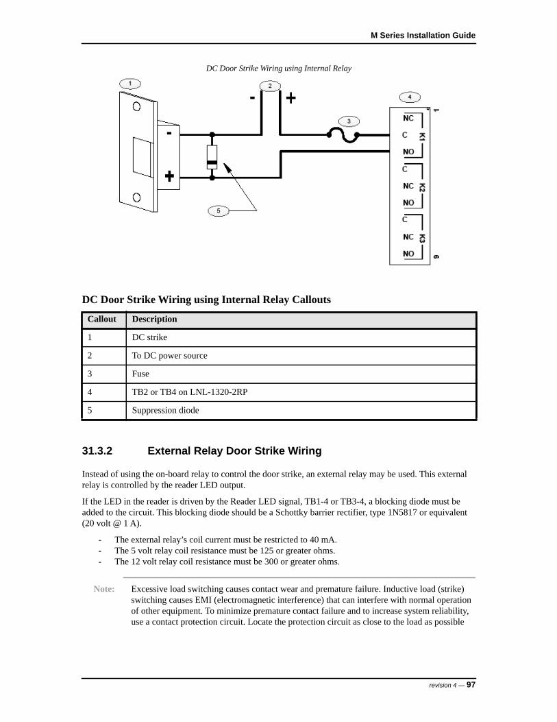
M Series Installation Guide
DC Door Strike Wiring using Internal Relay
31.3.2 External Relay Door Strike Wiring
Instead of using the on-board relay to control the door strike, an external relay may be used. This external relay is controlled by the reader LED output.
If the LED in the reader is driven by the Reader LED signal, TB1-4 or TB3-4, a blocking diode must be added to the circuit. This blocking diode should be a Schottky barrier rectifier, type 1N5817 or equivalent (20 volt @ 1 A).
- The external relay’s coil current must be restricted to 40 mA.- The 5 volt relay coil resistance must be 125 or greater ohms.- The 12 volt relay coil resistance must be 300 or greater ohms.
Note: Excessive load switching causes contact wear and premature failure. Inductive load (strike) switching causes EMI (electromagnetic interference) that can interfere with normal operation of other equipment. To minimize premature contact failure and to increase system reliability, use a contact protection circuit. Locate the protection circuit as close to the load as possible
DC Door Strike Wiring using Internal Relay Callouts
Callout Description
1 DC strike
2 To DC power source
3 Fuse
4 TB2 or TB4 on LNL-1320-2RP
5 Suppression diode
revision 4 — 97
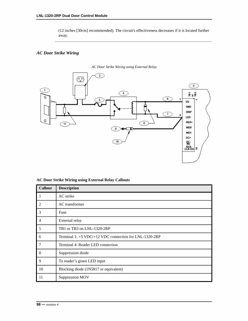
LNL-1320-2RP Dual Door Control Module
(12 inches [30cm] recommended). The circuit's effectiveness decreases if it is located further away.
AC Door Strike Wiring
AC Door Strike Wiring using External Relay
AC Door Strike Wiring using External Relay Callouts
Callout Description
1 AC strike
2 AC transformer
3 Fuse
4 External relay
5 TB1 or TB3 on LNL-1320-2RP
6 Terminal 1: +5 VDC/+12 VDC connection for LNL-1320-2RP
7 Terminal 4: Reader LED connection
8 Suppression diode
9 To reader’s green LED input
10 Blocking diode (1N5817 or equivalent)
11 Suppression MOV
98 — revision 4

M Series Installation Guide
DC Door Strike Wiring
DC Door Strike Wiring using External Relay
DC Door Strike Wiring using External Relay Callouts
Callout Description
1 DC strike
2 To DC power source
3 Fuse
4 External relay
5 TB1 or TB3 on LNL-1320-2RP
6 Terminal 1: +5 VDC/+12 VDC connection for LNL-1320-S2RP
7 Terminal 4: Reader LED connection
8 Suppression diode
9 To reader’s green LED input
10 Blocking diode (1N5817 or equivalent)
revision 4 — 99
LNL-1320-2RP Dual Door Control Module
32 Status LEDs
• Power-up: All LEDs are OFF- Initialization: After power is applied, the board initializes- Initialization complete: LEDs 1-4 briefly turn ON then OFF- Run time: See the following descriptions for LEDs 1-4
• LED 1: Heartbeat and online status:- Offline: 1 second cycle, 200 mS ON/800 mS OFF- Online (non-encrypted communication): Flash cycle of 800 mS ON/200 mS OFF- Online (encrypted communication): 4 flash cycles of 700 mS ON/300 mS OFF- Error indication: Waiting for firmware to download; flash cycle of 100 mS ON/100 mS OFF
• LED 2: SIO communication port status; indicates activity on the communication port• LED 3 (Reader Port 1): Flashes when receiving data from the reader (either input)• LED 4 (Reader Port 2): Flashes when data is received from the reader (either input)
100 — revision 4

M Series Installation Guide
33 Specifications
• Primary Power (from LNL-3300-M5): 12 VDC, ± 10 %, 155 mA maximum (plus reader current)• Relay Outputs: 6 outputs, Form-C, 2 A @ 30 VAC/DC, resistive• Inputs: 4 unsupervised, two per reader port• Reader Interface:
- Reader Power: 5 VDC or 12 VDC regulated (jumper selectable), 300 mA maximum each reader port
- Reader LED Output/External Relay: Open collector, 40 mA sink maximum- Reader Data Input: TTL compatible inputs- Communication: 9600, 19200, 38400, or 115200 bps, asynchronous
• Cable Requirements:- Alarm Inputs: 1 twisted pair per input, 22 AWG shielded. 30 ohms maximum loop resistance- Outputs: As required for the load- Reader Data: Use shielded cables;
– 5 VDC: 18 AWG, 200 ft. maximum, reader powered by reader processing board– 12 VDC: 20 AWG, 500 ft. maximum, reader powered by LNL-1320-2RP; 18 AWG, 3000 ft.
maximum, reader powered locally
Notes: The above specifications are based on the typical 12 volt reader drawing 125 mA. Reader power requirements vary between different models.
Excessive voltage drop on long cable runs may require a larger cable gauge or powering the reader from a local power source. Refer to the power specification for the reader being installed.
• Environmental:- Storage Temperature: -67 to +185°F (-55 to +85°C)- Operating Temperature: +32 to +158°F (0 to +70°C)- Humidity: 5 to 95% RHNC
• Mechanical:- Width: 3.5 in. (88.9 mm) - Length: 10.25 in. (260.4 mm)- Height: 0.69 in. (17.5 mm)- Weight (without connectors): 4.5 oz (126 g) nominal
revision 4 — 101

LNL-1320-2RP Dual Door Control Module
102 — revision 4

LNL-1320-S2RP DUAL DOOR CONTROL MODULE


M Series Installation Guide
34 Overview of the LNL-1320-S2RP
The LNL-1320-S2RP is a Dual Door Control Module that provides four (4) supervised inputs (two per reader interface port).
The LNL-1320-S2RP accepts data from readers with Clock/Data, Wiegand, F/2F, supervised F/2F signaling and door hardware. The LNL-1320-S2RP provides LED status, strike control and reader power of 5 VDC or 12 VDC.
Each of the two reader interface ports provides inputs for door position monitoring and request-to-exit (REX). The LNL-1320-S2RP also has three Form-C relay outputs used for strike control, alarm contact shunting and auxiliary device control for each reader.
LNL-1320-S2RP Dual Door Control Module
LNL-1320-S2RP Dual Door Control Module Callouts
Callout Desscription
1 J5: Reader voltage selection jumper
1
2
3
4
5
6
24
31
TB2
TB3
J5+5V
+12V
K3
K2
K1
K4
K5
K6
TB4
TB1
S1
J621 3 4 76 85
ON
10
VO
GND
DISP
LED
REX+
WD0
WD1DC+
NUDC-
REX-CLK DO
1
DC-
CLK DOREX-NU
DC+WD1
REX+
WD0
LED
DISP
GNDVO
101
11
99
NC
C
NO
C
NC
NO
C
NC
NO
K1
K2K3
C
NO
K6NC
K5
NO
NC
C
NO
K4C
NC
revision 4 — 105

LNL-1320-S2RP Dual Door Control Module
2 J6: to backplane in enclosure card cage
3 Status LEDs
4 DIP switches
5 Reader Port 2
6 Reader Port 1
LNL-1320-S2RP Dual Door Control Module Callouts
Callout Desscription
106 — revision 4

M Series Installation Guide
35 Configuration
Configuring the LNL-1320-S2RP consists of setting the device address and the power selection jumper.
35.1 Setting the Device Address and Baud Rate
Use the on-board DIP switches to set the device address and communication baud rate on the LNL-1320-S2RP.• Switches 1 to 5 select the device address.• Switches 6 and 7 select the communication baud rate.
Note: Currently, OnGuard only supports a baud rate of 38,4000 bps. Be sure to set both DIP Switches 6 and 7 to the ON position.
• Switch 8 enables encrypted communication.
All other configuration settings are set in the host software.
DIP Switch Settings for the LNL-1320-S2RP
Selection S1 S2 S3 S4 S5 S6 S7 S8
Address 0 OFF OFF OFF OFF OFF
Address 1 ON OFF OFF OFF OFF
Address 2 OFF ON OFF OFF OFF
Address 3 ON ON OFF OFF OFF
Address 4 OFF OFF ON OFF OFF
Address 5 ON OFF ON OFF OFF
Address 6 OFF ON ON OFF OFF
Address 7 ON ON ON OFF OFF
Address 8 OFF OFF OFF ON OFF
Address 9 ON OFF OFF ON OFF
Address 10 OFF ON OFF ON OFF
Address 11 ON ON OFF ON OFF
Address 12 OFF OFF ON ON OFF
Address 13 ON OFF ON ON OFF
Address 14 OFF ON ON ON OFF
Address 15 ON ON ON ON OFF
Address 16 OFF OFF OFF OFF ON
revision 4 — 107
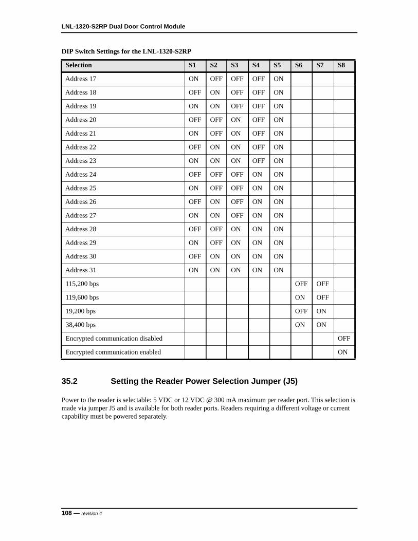
LNL-1320-S2RP Dual Door Control Module
35.2 Setting the Reader Power Selection Jumper (J5)
Power to the reader is selectable: 5 VDC or 12 VDC @ 300 mA maximum per reader port. This selection is made via jumper J5 and is available for both reader ports. Readers requiring a different voltage or current capability must be powered separately.
Address 17 ON OFF OFF OFF ON
Address 18 OFF ON OFF OFF ON
Address 19 ON ON OFF OFF ON
Address 20 OFF OFF ON OFF ON
Address 21 ON OFF ON OFF ON
Address 22 OFF ON ON OFF ON
Address 23 ON ON ON OFF ON
Address 24 OFF OFF OFF ON ON
Address 25 ON OFF OFF ON ON
Address 26 OFF ON OFF ON ON
Address 27 ON ON OFF ON ON
Address 28 OFF OFF ON ON ON
Address 29 ON OFF ON ON ON
Address 30 OFF ON ON ON ON
Address 31 ON ON ON ON ON
115,200 bps OFF OFF
119,600 bps ON OFF
19,200 bps OFF ON
38,400 bps ON ON
Encrypted communication disabled OFF
Encrypted communication enabled ON
DIP Switch Settings for the LNL-1320-S2RP
Selection S1 S2 S3 S4 S5 S6 S7 S8
108 — revision 4
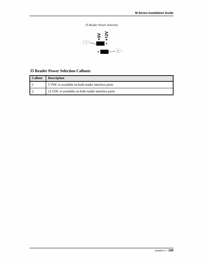
M Series Installation Guide
J5 Reader Power Selection
J5 Reader Power Selection Callouts
Callout Description
1 5 VDC is available on both reader interface ports
2 12 VDC is available on both reader interface ports
+12V
+5V
1
2
revision 4 — 109

LNL-1320-S2RP Dual Door Control Module
36 Reader Wiring
The reader ports on the LNL-1320-S2RP support the following reader types:
• Clock/Data• Wiegand• F/2F• Supervised F/2F
The following are basic reader cable requirements. For more information, refer to Specifications on page 124.
• F/2F and supervised F/2F readers require a shielded 4-conductor cable. • Clock/Data and Wiegand readers require a shielded 5-conductor cable.
Reader port configuration is defined by the host software.
36.1 LNL-1320-S2RP to Reader Wiring
Wiegand Reader
Wiegand Reader Callouts
Callout Description
1 Wiegand reader
2 TB1 or TB3 on LNL-1320-S2RP
3 Terminal 1: +5 VDC/+12 VDC connection
4 Terminal 2: Ground connection
1 2
TB1
or TB3
REX-CLK DO
DC+
NUDC-
4
7
6 WD0
WD1
LED
REX+
1
2
VO
GND
DISP
101
3
5
7
4
6
110 — revision 4

M Series Installation Guide
Magnetic Reader
5 Terminal 4: Door DO (Reader LED) connection
6 Terminal 6: Data 0 connection
7 Terminal 7: Data 1 connection
Magnetic Reader Callouts
Callout Description
1 Magnetic reader
2 TB1 or TB3 on LNL-1320-S2RP
3 Terminal 1: +5 VDC/+12 VDC connection
4 Terminal 2: Ground connection
5 Terminal 4: Door DO (Reader LED) connection
6 Terminal 6: Data connection
7 Terminal 7: Clock connection
Wiegand Reader Callouts
Callout Description
1 2
TB1
or TB3
REX-CLK DO
DC+
NUDC-
4
7
6 WD0
WD1
LED
REX+
1
2VO
GND
DISP
101
3
4
7
5
6
revision 4 — 111

LNL-1320-S2RP Dual Door Control Module
F/2F Reader
F/2F Reader Callouts
Callout Description
1 F/2F reader
2 TB1 or TB3 on LNL-1320-S2RP
3 Terminal 1: +5 VDC/+12 VDC connection
4 Terminal 2: Ground connection
5 Terminal 4: Door DO (Reader LED) connection
6 Terminal 7: Data 1 connection
1 2
REX-CLK DO 10
WD0
WD1
DC+
DC-NU
7
DISP
REX+
4 LED
1VO
2 GND
TB1
or TB3
1
3
4
6
5
112 — revision 4

M Series Installation Guide
Supervised F/2F Reader
36.2 Door Position Monitor and REX Input Wiring
Typically, the door position monitor switch uses the Normally Closed (NC) contact and the REX uses the Normally Open (NO) contact.
For the LNL-1320-S2RP, the door position monitor and REX switches can be wired in several different configurations.
These configurations are downloaded from the host and may be changed.
Supervised F/2F Reader Callouts
Callout Description
1 Supervised F/2F reader
2 TB1 or TB3 on LNL-1320-S2RP
3 Terminal 1: +5 VDC/+12 VDC connection
4 Terminal 2: Ground connection
5 Terminal 3: Display DO connection
6 Terminal 4: Door DO (Reader LED) connection
7 Terminal 7: Data 1 connection
8 Wire jumper to Terminal 3 (Display DO)
1 2
REX+
WD1
WD0
DC-
CLK DOREX-
DC+
7
10
NU
GND
VO
DISP
LED
1
4
2
TB1
or TB3
1
3
3
4
5
6
8
7
revision 4 — 113

LNL-1320-S2RP Dual Door Control Module
36.2.1 Supervised Inputs wired to the LNL-1320-S2RPSupervised inputs for the door position monitor and REX switches are wired to TB1 for the first reader, and TB3 for the second reader. Two sets of End-Of-Line (EOL) resistor pairs are supported by the S2RP board.
Either two 1K ohm resistors, or a 6.8K and 18K ohm resistor set must be installed as shown in the following figures. Install the EOL resistors as close to the switch as possible to maximize supervision’s effectiveness.
In addition to detecting contact open or contact closed, the LNL-1320-S2RP also monitors for the following abnormal circuit conditions: open circuit, shorted circuit, grounding of either side of the circuit, or the introduction of a foreign voltage.
Note: Grounded and foreign voltage states are not required by UL 294 and therefore not verified by UL.
Supervised Input Wiring with 1K/1K EOL
Supervised Input Wiring with 1K/1K EOL Callouts
Callout Description
1 TB1 or TB3 on LNL-1320-S2RP
2 Normally Open contact for REX switch
114 — revision 4

M Series Installation Guide
Supervised Input Wiring with 6.8K/18K EOL
36.2.2 Unsupervised Inputs wired to the F/2F Reader
Unsupervised inputs for the door position monitor and REX switches are wired directly to the F/2F reader configured for 2-State Supervision. See the reader’s documentation for the proper connection terminals. End-Of-Line (EOL) resistors are not required.
3 Normally Closed contact for door monitor switch
Supervised Input Wiring with 6.8K/18K EOL Callouts
Callout Description
1 TB1 or TB3 on LNL-1320-S2RP
2 Normally Open contact for REX switch
3 Normally Closed contact for door monitor switch
Supervised Input Wiring with 1K/1K EOL Callouts
Callout Description
revision 4 — 115
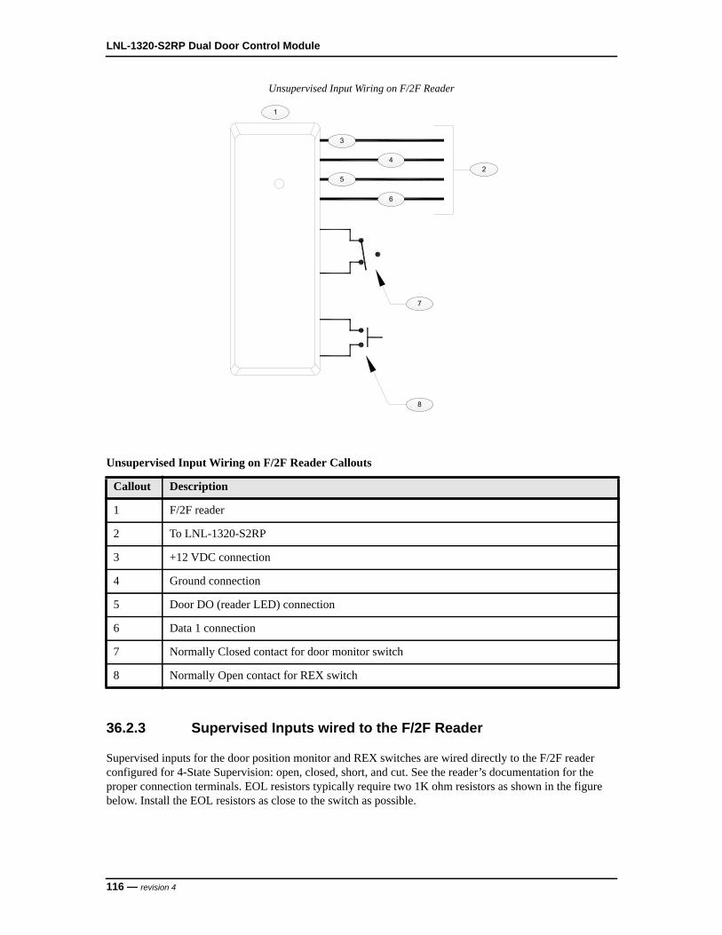
LNL-1320-S2RP Dual Door Control Module
Unsupervised Input Wiring on F/2F Reader
36.2.3 Supervised Inputs wired to the F/2F Reader
Supervised inputs for the door position monitor and REX switches are wired directly to the F/2F reader configured for 4-State Supervision: open, closed, short, and cut. See the reader’s documentation for the proper connection terminals. EOL resistors typically require two 1K ohm resistors as shown in the figure below. Install the EOL resistors as close to the switch as possible.
Unsupervised Input Wiring on F/2F Reader Callouts
Callout Description
1 F/2F reader
2 To LNL-1320-S2RP
3 +12 VDC connection
4 Ground connection
5 Door DO (reader LED) connection
6 Data 1 connection
7 Normally Closed contact for door monitor switch
8 Normally Open contact for REX switch
1
2
3
4
5
6
7
8
116 — revision 4

M Series Installation Guide
Supervised Input Wiring on F/2F Reader
36.3 Door Strike Wiring
There are two options for door strike wiring on the LNL-1320-S2RP: internal relay and external relay.
Each relay option can be wired for AC or DC current.
36.3.1 Internal Relay Door Strike WiringEach reader port on the LNL-1320-S2RP has three Form-C contact relays for controlling door strikes or other devices. Relay contact rating: 2 A @ 30 VAC/DC maximum.
Supervised Input Wiring on F/2F Reader Callouts
Callout Description
1 Supervised F/2F reader
2 To LNL-1320-S2RP
3 +5 VDC/+12 VDC connection
4 Ground connection
5 Door DO (reader LED) connection
6 Data 1 connection
7 Normally Closed contact for door monitor switch
8 Normally Open contact for REX switch
1
2
7
8
1K,1%
1K,1%
1K,1%
1K,1%
3
4
5
6
revision 4 — 117
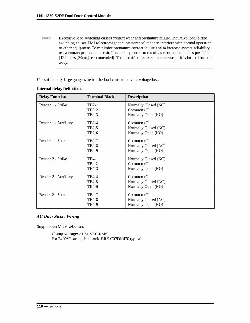
LNL-1320-S2RP Dual Door Control Module
Note: Excessive load switching causes contact wear and premature failure. Inductive load (strike) switching causes EMI (electromagnetic interference) that can interfere with normal operation of other equipment. To minimize premature contact failure and to increase system reliability, use a contact protection circuit. Locate the protection circuit as close to the load as possible (12 inches [30cm] recommended). The circuit's effectiveness decreases if it is located further away.
Use sufficiently large gauge wire for the load current to avoid voltage loss.
AC Door Strike Wiring
Suppression MOV selection:
- Clamp voltage: >1.5x VAC RMS- For 24 VAC strike, Panasonic ERZ-C07DK470 typical
Internal Relay Definitions
Relay Function Terminal Block Description
Reader 1 - Strike TB2-1TB2-2TB2-3
Normally Closed (NC)Common (C)Normally Open (NO)
Reader 1 - Auxiliary TB2-4TB2-5TB2-6
Common (C)Normally Closed (NC)Normally Open (NO)
Reader 1 - Shunt TB2-7TB2-8TB2-9
Common (C)Normally Closed (NC)Normally Open (NO)
Reader 2 - Strike TB4-1TB4-2TB4-3
Normally Closed (NC)Common (C)Normally Open (NO)
Reader 2 - Auxiliary TB4-4TB4-5TB4-6
Common (C)Normally Closed (NC)Normally Open (NO)
Reader 2 - Shunt TB4-7TB4-8TB4-9
Common (C)Normally Closed (NC)Normally Open (NO)
118 — revision 4

M Series Installation Guide
AC Door Strike Wiring using Internal Relay
DC Door Strike Wiring
Suppression diode selection:
- Diode current rating: >1x strike current- Diode breakdown voltage: 4x strike voltage- For 12 VDC or 24 VDC strike, use diode 1N4002 (100 V/1 A) typical
AC Door Strike Wiring using Internal Relay Callouts
Callout Description
1 AC strike
2 To AC power source
3 Fuse
4 TB2 or TB4 on LNL-1320-S2RP
5 Suppression MOV
revision 4 — 119

LNL-1320-S2RP Dual Door Control Module
DC Door Strike Wiring using Internal Relay
36.3.2 External Relay Door Strike Wiring
Instead of using the on-board relay to control the door strike, an external relay may be used. This external relay is controlled by the reader LED output.
If the LED in the reader is driven by the Reader LED signal, TB1-4 or TB3-4, a blocking diode must be added to the circuit. This blocking diode should be a Schottky barrier rectifier, type 1N5817 or equivalent (20 volt @ 1 A).
- The external relay’s coil current must be restricted to 40 mA.- The 5 volt relay coil resistance must be 125 or greater ohms.- The 12 volt relay coil resistance must be 300 or greater ohms.
Note: Excessive load switching causes contact wear and premature failure. Inductive load (strike) switching causes EMI (electromagnetic interference) that can interfere with normal operation of other equipment. To minimize premature contact failure and to increase system reliability, use a contact protection circuit. Locate the protection circuit as close to the load as possible
DC Door Strike Wiring using Internal Relay Callouts
Callout Description
1 DC strike
2 To DC power source
3 Fuse
4 TB2 or TB4 on LNL-1320-S2RP
5 Suppression diode
120 — revision 4

M Series Installation Guide
(12 inches [30cm] recommended). The circuit's effectiveness decreases if it is located further away.
AC Door Strike Wiring
AC Door Strike Wiring using External Relay
AC Door Strike Wiring using External Relay Callouts
Callout Description
1 AC strike
2 AC transformer
3 Fuse
4 External relay
5 TB1 or TB3 on LNL-1320-S2RP
6 Terminal 1: +5 VDC/+12 VDC connection for LNL-1320-S2RP
7 Terminal 4: Reader LED connection
8 Suppression diode
9 To reader’s green LED input
10 Blocking diode (1N5817 or equivalent)
11 Suppression MOV
revision 4 — 121

LNL-1320-S2RP Dual Door Control Module
DC Door Strike Wiring
DC Door Strike Wiring using External Relay
DC Door Strike Wiring using External Relay Callouts
Callout Description
1 DC strike
2 To DC power source
3 Fuse
4 External relay
5 TB1 or TB3 on LNL-1320-S2RP
6 Terminal 1: +5 VDC/+12 VDC connection for LNL-1320-S2RP
7 Terminal 4: Reader LED connection
8 Suppression diode
9 To reader’s green LED input
10 Blocking diode (1N5817 or equivalent)
122 — revision 4

M Series Installation Guide
37 Status LEDs
• Power-up: All LEDs are OFF- Initialization: After power is applied, the board initializes- Initialization complete: LEDs 1-4 briefly turn ON then OFF- Run time: See the following descriptions for LEDs 1-4
• LED 1: Heartbeat and online status:- Offline: 1 second cycle, 200 mS ON/800 mS OFF- Online (non-encrypted communication): Flash cycle of 800 mS ON/200 mS OFF- Online (encrypted communication): 4 flash cycles of 700 mS ON/300 mS OFF- Error indication: Waiting for firmware to download; flash cycle of 100 mS ON/100 mS OFF
• LED 2: SIO communication port status; indicates activity on the communication port• LED 3 (Reader Port 1): Flashes when receiving data from the reader (either input)• LED 4 (Reader Port 2): Flashes when data is received from the reader (either input)
revision 4 — 123
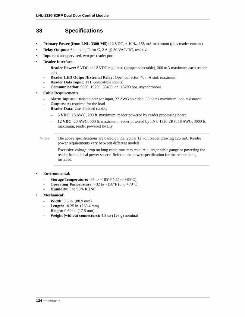
LNL-1320-S2RP Dual Door Control Module
38 Specifications
• Primary Power (from LNL-3300-M5): 12 VDC, ± 10 %, 155 mA maximum (plus reader current)• Relay Outputs: 6 outputs, Form-C, 2 A @ 30 VAC/DC, resistive• Inputs: 4 unsupervised, two per reader port• Reader Interface:
- Reader Power: 5 VDC or 12 VDC regulated (jumper selectable), 300 mA maximum each reader port
- Reader LED Output/External Relay: Open collector, 40 mA sink maximum- Reader Data Input: TTL compatible inputs- Communication: 9600, 19200, 38400, or 115200 bps, asynchronous
• Cable Requirements:- Alarm Inputs: 1 twisted pair per input, 22 AWG shielded. 30 ohms maximum loop resistance- Outputs: As required for the load- Reader Data: Use shielded cables;
– 5 VDC: 18 AWG, 200 ft. maximum, reader powered by reader processing board– 12 VDC: 20 AWG, 500 ft. maximum, reader powered by LNL-1320-2RP; 18 AWG, 3000 ft.
maximum, reader powered locally
Notes: The above specifications are based on the typical 12 volt reader drawing 125 mA. Reader power requirements vary between different models.
Excessive voltage drop on long cable runs may require a larger cable gauge or powering the reader from a local power source. Refer to the power specification for the reader being installed.
• Environmental:- Storage Temperature: -67 to +185°F (-55 to +85°C)- Operating Temperature: +32 to +158°F (0 to +70°C)- Humidity: 5 to 95% RHNC
• Mechanical:- Width: 3.5 in. (88.9 mm) - Length: 10.25 in. (260.4 mm)- Height: 0.69 in. (17.5 mm)- Weight (without connectors): 4.5 oz (126 g) nominal
124 — revision 4

LNL-1380-8RP READER INTERFACE MODULE

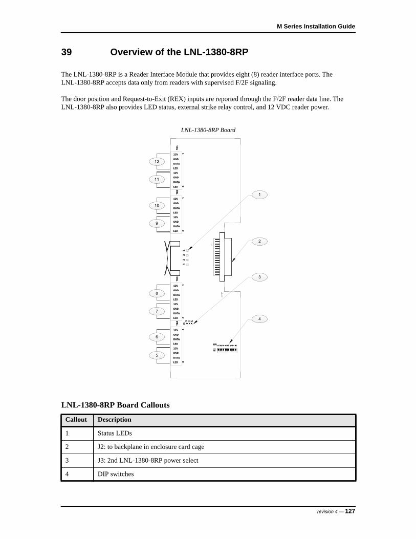
M Series Installation Guide
39 Overview of the LNL-1380-8RP
The LNL-1380-8RP is a Reader Interface Module that provides eight (8) reader interface ports. The LNL-1380-8RP accepts data only from readers with supervised F/2F signaling.
The door position and Request-to-Exit (REX) inputs are reported through the F/2F reader data line. The LNL-1380-8RP also provides LED status, external strike relay control, and 12 VDC reader power.
LNL-1380-8RP Board
LNL-1380-8RP Board Callouts
Callout Description
1 Status LEDs
2 J2: to backplane in enclosure card cage
3 J3: 2nd LNL-1380-8RP power select
4 DIP switches
S1
4
5321 4ON 76 8
43
21
DATA
LED
12V
GND
DATA
LED
12V
GND
TB1
18
TB2
2
18LED
DATA
GND
12V
12V
DATA
LED
GND
12V
GND
LED
DATA
12V
GND
DATA
LED
18
TB3
12V
GND
LED
DATA
12V
GND
DATA
LED
18
TB4
J3
123
1
3
12
9
11
10
5
6
7
8
revision 4 — 127

LNL-1380-8RP Reader Interface Module
5 Reader 8
6 Reader 7
7 Reader 6
8 Reader 5
9 Reader 4
10 Reader 3
11 Reader 2
12 Reader 1
LNL-1380-8RP Board Callouts
Callout Description
128 — revision 4

M Series Installation Guide
40 Configuration
Configuring the LNL-1380-8RP consists of setting the device address and the power selection jumper.
40.1 Setting the Device Address and Baud Rate
Use the on-board DIP switches to set the device address and communication baud rate on the LNL-1380-8RP.• Switches 1 to 5 select the device address.• Switches 6 and 7 select the communication baud rate.
Note: Currently, OnGuard only supports a baud rate of 38,4000 bps. Be sure to set both DIP Switches 6 and 7 to the ON position.
• Switch 8 enables encrypted communication.
All other configuration settings are set in the host software.
DIP Switch Settings for the LNL-1320-S2RP
Selection S1 S2 S3 S4 S5 S6 S7 S8
Address 0 OFF OFF OFF OFF OFF
Address 1 ON OFF OFF OFF OFF
Address 2 OFF ON OFF OFF OFF
Address 3 ON ON OFF OFF OFF
Address 4 OFF OFF ON OFF OFF
Address 5 ON OFF ON OFF OFF
Address 6 OFF ON ON OFF OFF
Address 7 ON ON ON OFF OFF
Address 8 OFF OFF OFF ON OFF
Address 9 ON OFF OFF ON OFF
Address 10 OFF ON OFF ON OFF
Address 11 ON ON OFF ON OFF
Address 12 OFF OFF ON ON OFF
Address 13 ON OFF ON ON OFF
Address 14 OFF ON ON ON OFF
Address 15 ON ON ON ON OFF
Address 16 OFF OFF OFF OFF ON
revision 4 — 129
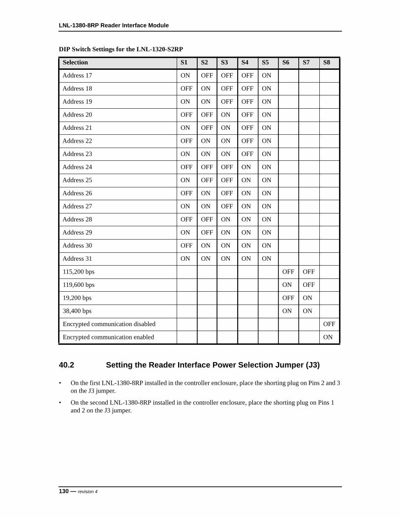
LNL-1380-8RP Reader Interface Module
40.2 Setting the Reader Interface Power Selection Jumper (J3)
• On the first LNL-1380-8RP installed in the controller enclosure, place the shorting plug on Pins 2 and 3 on the J3 jumper.
• On the second LNL-1380-8RP installed in the controller enclosure, place the shorting plug on Pins 1 and 2 on the J3 jumper.
Address 17 ON OFF OFF OFF ON
Address 18 OFF ON OFF OFF ON
Address 19 ON ON OFF OFF ON
Address 20 OFF OFF ON OFF ON
Address 21 ON OFF ON OFF ON
Address 22 OFF ON ON OFF ON
Address 23 ON ON ON OFF ON
Address 24 OFF OFF OFF ON ON
Address 25 ON OFF OFF ON ON
Address 26 OFF ON OFF ON ON
Address 27 ON ON OFF ON ON
Address 28 OFF OFF ON ON ON
Address 29 ON OFF ON ON ON
Address 30 OFF ON ON ON ON
Address 31 ON ON ON ON ON
115,200 bps OFF OFF
119,600 bps ON OFF
19,200 bps OFF ON
38,400 bps ON ON
Encrypted communication disabled OFF
Encrypted communication enabled ON
DIP Switch Settings for the LNL-1320-S2RP
Selection S1 S2 S3 S4 S5 S6 S7 S8
130 — revision 4
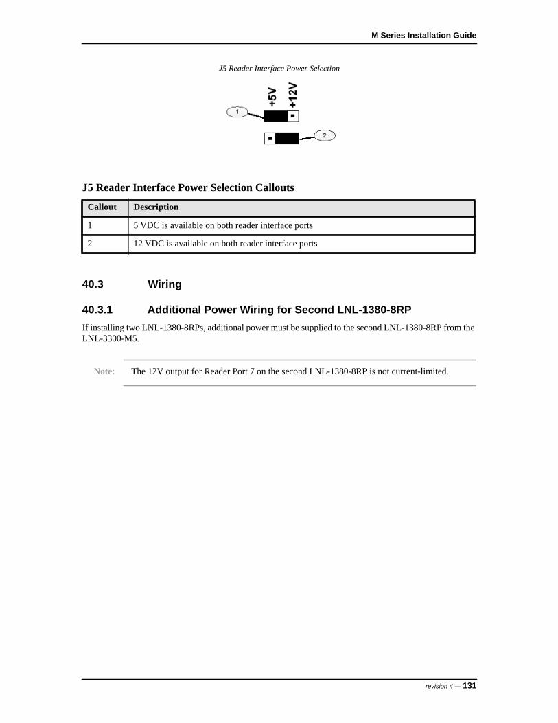
M Series Installation Guide
J5 Reader Interface Power Selection
40.3 Wiring
40.3.1 Additional Power Wiring for Second LNL-1380-8RPIf installing two LNL-1380-8RPs, additional power must be supplied to the second LNL-1380-8RP from the LNL-3300-M5.
Note: The 12V output for Reader Port 7 on the second LNL-1380-8RP is not current-limited.
J5 Reader Interface Power Selection Callouts
Callout Description
1 5 VDC is available on both reader interface ports
2 12 VDC is available on both reader interface ports
revision 4 — 131
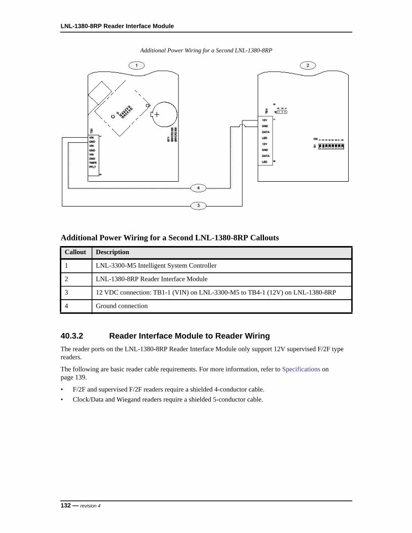
LNL-1380-8RP Reader Interface Module
Additional Power Wiring for a Second LNL-1380-8RP
40.3.2 Reader Interface Module to Reader WiringThe reader ports on the LNL-1380-8RP Reader Interface Module only support 12V supervised F/2F type readers.
The following are basic reader cable requirements. For more information, refer to Specifications on page 139.
• F/2F and supervised F/2F readers require a shielded 4-conductor cable. • Clock/Data and Wiegand readers require a shielded 5-conductor cable.
Additional Power Wiring for a Second LNL-1380-8RP Callouts
Callout Description
1 LNL-3300-M5 Intelligent System Controller
2 LNL-1380-8RP Reader Interface Module
3 12 VDC connection: TB1-1 (VIN) on LNL-3300-M5 to TB4-1 (12V) on LNL-1380-8RP
4 Ground connection
132 — revision 4
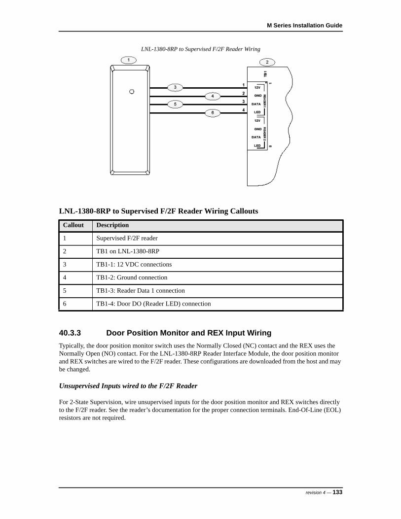
M Series Installation Guide
LNL-1380-8RP to Supervised F/2F Reader Wiring
40.3.3 Door Position Monitor and REX Input WiringTypically, the door position monitor switch uses the Normally Closed (NC) contact and the REX uses the Normally Open (NO) contact. For the LNL-1380-8RP Reader Interface Module, the door position monitor and REX switches are wired to the F/2F reader. These configurations are downloaded from the host and may be changed.
Unsupervised Inputs wired to the F/2F Reader
For 2-State Supervision, wire unsupervised inputs for the door position monitor and REX switches directly to the F/2F reader. See the reader’s documentation for the proper connection terminals. End-Of-Line (EOL) resistors are not required.
LNL-1380-8RP to Supervised F/2F Reader Wiring Callouts
Callout Description
1 Supervised F/2F reader
2 TB1 on LNL-1380-8RP
3 TB1-1: 12 VDC connections
4 TB1-2: Ground connection
5 TB1-3: Reader Data 1 connection
6 TB1-4: Door DO (Reader LED) connection
revision 4 — 133

LNL-1380-8RP Reader Interface Module
Unsupervised Input Wiring on the F/2F Reader
Supervised Inputs wired to the F/2F Reader
For 4-State Supervision, wire supervised inputs for the door position monitor and REX switches directly to the F/2F reader. See the reader’s documentation for the proper connection terminals. EOL resistors typically require two 1K ohm resistors. Install the EOL resistors as close to the switch as possible (within 12 inches [30cm] recommended).
Unsupervised Input Wiring on the F/2F Reader Callouts
Callout Description
1 F/2F reader
2 To LNL-1380-8RP
3 +5 VDC/+12 VDC connection
4 Ground connection
5 Door DO (reader LED) connection
6 Data 1 connection
7 Normally Closed contact for door monitor switch
8 Normally Open contact for REX switch
134 — revision 4

M Series Installation Guide
Supervised Input Wiring on the F/2F Reader
40.3.4 Door Strike Wiring using an External Relay
An external relay may be used to control a door strike. This external relay is controlled by the reader LED output on the LNL-1380-8RP. The external relay can be wired for AC or DC current.
If the LED in the reader is driven by the Reader LED signal, TB1-4 or TB3-4, a blocking diode must be added to the circuit. This blocking diode should be a Schottky barrier rectifier, type 1N5817 or equivalent (20 volt @ 1 A).
- The external relay’s coil current must be restricted to 40 mA.- The 5 volt relay coil resistance must be 125 or greater ohms.
Supervised Input Wiring on the F/2F Reader Callouts
Callout Description
1 Supervised F/2F reader
2 To LNL-1380-8RP
3 +12 VDC connection
4 Ground connection
5 Door DO (reader LED) connection
6 Data 1 connection
7 Normally Closed contact for door monitor switch
8 Normally Open contact for REX switch
revision 4 — 135

LNL-1380-8RP Reader Interface Module
The 12 volt relay coil resistance must be 300 or greater ohms.
Note: Excessive load switching causes contact wear and premature failure. Inductive load (strike) switching causes EMI (electromagnetic interference) that can interfere with normal operation of other equipment. To minimize premature contact failure and to increase system reliability, use a contact protection circuit. Locate the protection circuit as close to the load as possible (12 inches [30cm] recommended). The circuit's effectiveness decreases if it is located further away.
AC Door Strike Wiring using External Relay
AC Door Strike Wiring using External Relay Callouts
Callout Description
1 AC strike
2 AC transformer
3 Fuse
4 External relay
5 TB1 on LNL-1380-8RP
6 Terminal 1: +12 VDC connection for LNL-1380-8RP
7 Terminal 4: Reader LED connection
8 Suppression diode
9 To reader’s green LED input
136 — revision 4

M Series Installation Guide
DC Door Strike Wiring
DC Door Strike Wiring using External Relay
10 Blocking diode (1N5817 or equivalent)
11 Suppression MOV
DC Door Strike Wiring using External Relay Callouts
Callout Description
1 DC strike
2 To DC power source
3 Fuse
4 External relay
5 TB1 on LNL-1380-8RP
6 Terminal 1: +12 VDC connection for LNL-1380-8RP
7 Terminal 4: Reader LED connection
8 Suppression diode
9 To reader’s green LED input
10 Blocking diode (1N5817 or equivalent)
AC Door Strike Wiring using External Relay Callouts
Callout Description
revision 4 — 137

LNL-1380-8RP Reader Interface Module
41 Status LEDs
• Power-up: All LEDs are OFF- Initialization: After power is applied, the board initializes- Initialization complete: LEDs 1-4 briefly turn ON then OFF- Run time: See the following descriptions for LEDs 1-4
• LED 1: Heartbeat and online status:- Offline: 1 second cycle, 200 mS ON/800 mS OFF- Online (non-encrypted communication): Flash cycle of 800 mS ON/200 mS OFF- Online (encrypted communication): 4 flash cycles of 700 mS ON/300 mS OFF- Error indication: Waiting for firmware to download; flash cycle of 100 mS ON/100 mS OFF
• LED 2: SIO communication port status; indicates activity on the communication port• LED 3 (Reader Port 1): Flashes when receiving data from the reader (any of the eight reader ports)• LED 4 (Reader Port 2): Flashes when supervised F/2F reader acknowledgment is sent on any of the
eight readers, indicating that a reader port is configured for supervised F/2F.
138 — revision 4
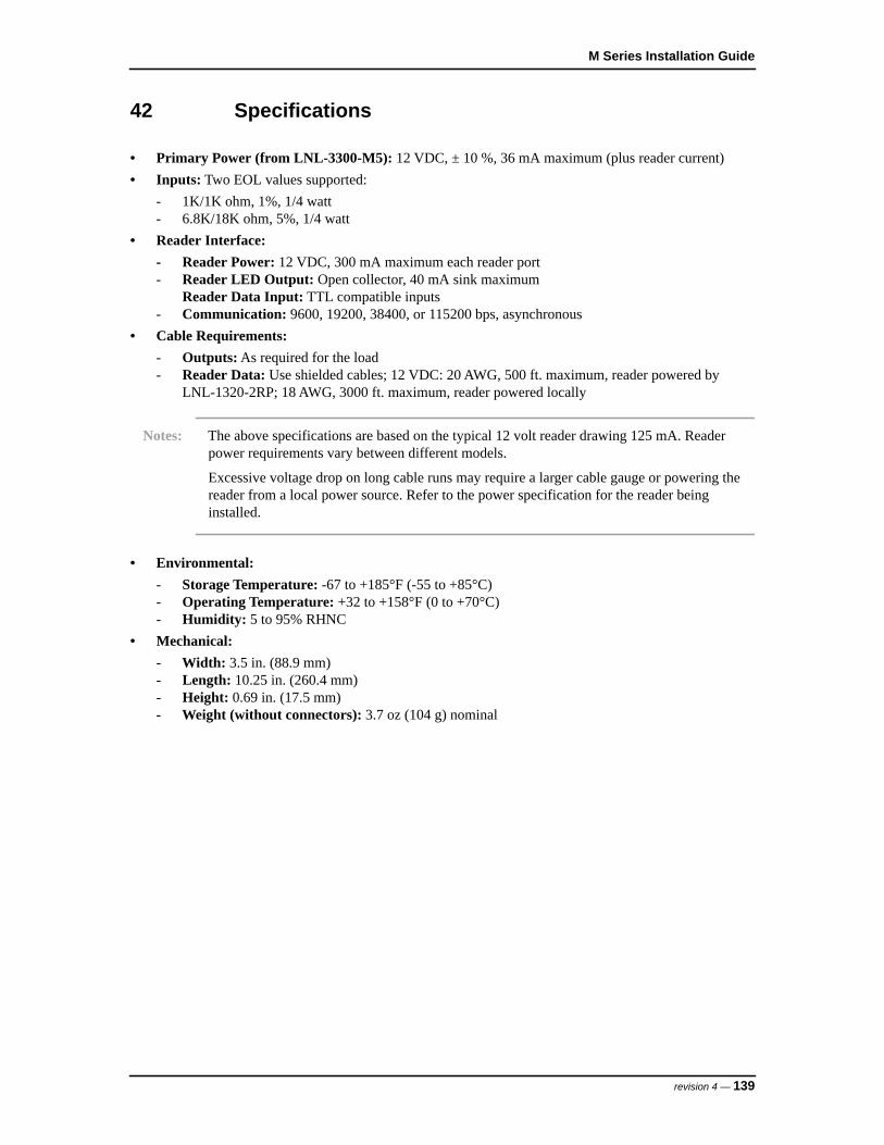
M Series Installation Guide
42 Specifications
• Primary Power (from LNL-3300-M5): 12 VDC, ± 10 %, 36 mA maximum (plus reader current)• Inputs: Two EOL values supported:
- 1K/1K ohm, 1%, 1/4 watt- 6.8K/18K ohm, 5%, 1/4 watt
• Reader Interface:- Reader Power: 12 VDC, 300 mA maximum each reader port- Reader LED Output: Open collector, 40 mA sink maximum
Reader Data Input: TTL compatible inputs- Communication: 9600, 19200, 38400, or 115200 bps, asynchronous
• Cable Requirements:- Outputs: As required for the load- Reader Data: Use shielded cables; 12 VDC: 20 AWG, 500 ft. maximum, reader powered by
LNL-1320-2RP; 18 AWG, 3000 ft. maximum, reader powered locally
Notes: The above specifications are based on the typical 12 volt reader drawing 125 mA. Reader power requirements vary between different models.
Excessive voltage drop on long cable runs may require a larger cable gauge or powering the reader from a local power source. Refer to the power specification for the reader being installed.
• Environmental:- Storage Temperature: -67 to +185°F (-55 to +85°C)- Operating Temperature: +32 to +158°F (0 to +70°C)- Humidity: 5 to 95% RHNC
• Mechanical:- Width: 3.5 in. (88.9 mm) - Length: 10.25 in. (260.4 mm)- Height: 0.69 in. (17.5 mm)- Weight (without connectors): 3.7 oz (104 g) nominal
revision 4 — 139

LNL-1380-8RP Reader Interface Module
140 — revision 4
LNL-8000-MCOM RS-485 INTERFACE MODULE


M Series Installation Guide
43 Overview of the LNL-8000-MCOM
The LNL-8000-MCOM is an RS-485 Interface Module that connects the first controller enclosure, which contains the LNL-3300-M5 Intelligent System Controller (ISC), to downstream controller enclosures.
The LNL-8000-MCOM accepts 12 VDC power and two-wire RS-485 communication.
A local 12 VDC power supply powers the I/O modules in the controller enclosure. The LNL-3300-M5 (located in the first controller enclosure) communicates with the downstream controller enclosure using multi-drop two-wire RS-485.
LNL-8000-MCOM RS-485 Interface Module
LNL-8000-MCOM RS-485 Interface Module Callouts
Callout Description
1 J1: to backplane in enclosure card cage
2 Terminal Block 1 (TB1): 12 VDC power inputs
3 Terminal Block 2 (TB2): to/from upstream/downstream enclosures
revision 4 — 143

LNL-8000-MCOM RS-485 Interface Module
44 Wiring
Wiring the LNL-8000-MCOM consists of:
• Communication Wiring on page 144• Input Power Wiring on page 145• Enclosure Tamper and Power Fault Wiring on page 146
44.1 Communication Wiring
Terminal Block 2 (TB2) is a two-wire RS-485 interface that communicates to upstream and downstream controller enclosures.
TB2 on the LNL-3300-M5 (located in the first M5 enclosure) is wired to TB2 on the LNL-8000-MCOM in each downstream enclosure.
This interface allows multi-drop communication on a single bus up to 4,000 ft. (1,200 m).
Use shielded twisted pair (24 AWG minimum) cable with 120 ohm impedance.
LNL-8000-MCOM Communication Wiring
LNL-8000-MCOM Communication Wiring Callouts
Callout Description
1 Shield
2 Drain wire
3 TB2 on LNL-8000-MCOM
144 — revision 4

M Series Installation Guide
44.2 Input Power Wiring
The LNL-8000-MCOM requires 12 VDC power, 3 A minimum. This power is passed through to the back plane to power the I/O modules in the M5 enclosure.
There are three pairs of connections for power, all in parallel, on Terminal Block 1 (TB1). If needed, the other two pairs can supply power to the other I/O boards.
To wire the input power:
1. Locate the power source as close to the LNL-8000-MCOM as possible.
2. Connect the incoming +12 VDC to TB1-3, and ground (12 VDC return) to TB1-4. Use at least 18 AWG wire.
Notes: Depending on the system configuration, a larger power supply may be required.
Connect the GND signal to earth ground in one location within the system. Multiple earth ground connections are not recommended as they can cause group loop problems.
Observe polarity on the 12 VDC input.
LNL-8000-MCOM Input Power Wiring
LNL-8000-MCOM Input Power Wiring Callouts
Callout Description
1 12 VDC power supply, 3 A minimum
2 TB1 on LNL-8000-MCOM
3 TB1-3: +12 VDC connection
4 TB1-4: Ground (12 VDC return) connection
revision 4 — 145
LNL-8000-MCOM RS-485 Interface Module
44.3 Enclosure Tamper and Power Fault Wiring
The LNL-3300-M5 has two dedicated inputs for enclosure tamper (TMPR) and UPS fault monitoring (PFLT). The LNL-8000-MCOM installed in downstream controller enclosures does not have these dedicated inputs.
There are three options available to wire tamper and power fault switches in downstream controller enclosures:
• Wire the tamper and power fault switches in series from the first controller enclosure to downstream controller enclosures. Use conduit when wiring from one enclosure to the next, and ensure the conduit is inaccessible. With this option, the user cannot determine which controller enclosure is reporting the alarm.
• Wire the tamper and power fault switches to available inputs on the LNL-1100-20DI board.• Wire the tamper and power fault switches to available reader port inputs.
The inputs on the LNL-1100-20DI, LNL-1320-2RP, and the LNL-1320-S2RP are monitor points configured as unsupervised, Normally Closed contacts.
For more information regarding wiring details, refer to:
• LNL-1320-2RP Reader Wiring on page 88• LNL-1320-S2RP Reader Wiring on page 110• LNL-1100-20DI Alarm Input Wiring on page 55
146 — revision 4
M Series Installation Guide
45 Specifications
• Primary Power: Not applicable. Power is passed through and supplies power to the controller enclosure back plane.
• Communication: Two-wire RS-485 at 9600, 19200, 38400, or 115200 bps, asynchronous, passed through to the back plane.
• Cable Requirements:- Power: 1 twisted pair, 18 AWG- RS-485: 24 AWG; 4,000 ft. (1,200 m) maximum; shielded twisted pair; 120 ohm impedance
• Environmental:- Storage Temperature: -67 to +185 °F (-55 to +85 °C)- Operating Temperature: +32 to +158 °F (0 to +70 °C)- Humidity: 5 to 95% RHNC
• Mechanical:- Width: 3.5 in. (88.9 mm)- Length: 10.25 in. (260.4 mm)- Height: 0.6 in. (15.24 mm)- Weight (without connectors): 3.4 oz (96.5 g) nominal
revision 4 — 147

LNL-8000-MCOM RS-485 Interface Module
148 — revision 4
M Series Installation Guide
Index
AAC
door strike wiringexternal relay ...................... 98, 121, 136internal relay................ 95, 96, 118, 119LNL-1200-16DOR ............................... 77
Alarminput wiring, LNL-1100-20DI ..................... 55
Alarm priorityUL................................................................ 29
BBattery
clockbackup
LNL-3300-M5............................... 45install backup ............................................... 17memory
backupLNL-3300-M5............................... 45
Baud Ratesetting
LNL-1100-20DI ................................... 53LNL-1200-16DO.................................. 63LNL-1200-16DOR ............................... 73LNL-1320-2RP..................................... 85LNL-1320-S2RP................................. 107LNL-1380-8RP................................... 129
Bulk erase functionLNL-3300-M5 ............................................. 45
CCable
length ........................................................... 12routing.......................................................... 12
Card formatsUL evaluated................................................ 28
Certified installationsUL requirements .......................................... 25
Clockreal time
LNL-3300-M5 ...................................... 45Communication
troubleshooting ............................................ 24wiring
LNL-3300-M5 ...................................... 39LNL-8000-MCOM............................. 144
Configurationhost application
LNL-3300-M5 ...................................... 44LNL-1320-2RP............................................ 85LNL-1320-S2RP........................................ 107web
first-time login ...................................... 41web page ...................................................... 41
DDC
door strike wiringexternal relay ...................... 99, 122, 137internal relay................ 96, 97, 119, 120
Device addresssetting
LNL-1100-20DI ................................... 53LNL-1200-16DO.................................. 63LNL-1200-16DOR ............................... 73LNL-1320-2RP..................................... 85LNL-1320-S2RP................................. 107LNL-1380-8RP................................... 129
DIP switchesLNL-1100-20DI........................................... 53LNL-1200-16DO ......................................... 63LNL-1200-16DOR ...................................... 73LNL-1320-2RP............................................ 85LNL-1320-S2RP........................................ 107LNL-1380-8RP.......................................... 129LNL-3300-M5 ............................................. 35
DoorAC strike wiring
external relay ...................... 98, 121, 136internal relay................ 95, 96, 118, 119LNL-1200-16DOR ............................... 77
DC strike wiringexternal relay ...................... 99, 122, 137internal relay................ 96, 97, 119, 120LNL-1200-16DOR ............................... 76
dual control moduleLNL-1320-2RP..................................... 83LNL-1320-S2RP................................. 105wire to reader ............................... 88, 110
external relay strike wiring ................. 97, 120internal relay strike wiring.................. 94, 117position monitor wiring ...................... 91, 113
Door striketroubleshooting ............................................ 23
EElectrostatic Discharge (ESD) ............................ 11
revision 4 — 149

Index
Enclosure tamperLNL-3300-M5 ............................................. 18LNL-8000-MCOM ...................................... 19wiring
LNL-3300-M5 ...................................... 40LNL-8000-MCOM............................. 146
FF/2F reader
REX input wiringunsupervised inputs ..................... 92, 115
supervised input wiring...... 91, 93, 113, 116, 134
unsupervised input wiring.......... 92, 115, 133
HHardware installation guidelines........................... 7
IInput control module
LNL-1100-20DI........................................... 51Installation
battery backup.............................................. 17cable length.................................................. 12cable routing ................................................ 12general rules................................................. 11mounting ...................................................... 12mounting instructions .................................. 13noise prevention........................................... 11outline .......................................................... 10power setup.................................................. 15power supply................................................ 15signal transmission....................................... 11UL typical combinations.............................. 28
Intelligent system controllerLNL-3300-M5 ............................................. 33
JJumpers
LNL-1320-2RPJ5 reader power selection ..................... 86
LNL-1320-S2RPJ5 reader power selection ................... 108
LNL-1380-8RPJ3 reader interface power selection .... 130
LNL-3300-M5J4 termination jumper........................... 35
LLEDs
statusLNL-3300-M5 ...................................... 46
LNL-1100-20DIalarm inputs ................................................. 55DIP switches ................................................ 53setting the baud rate ..................................... 53setting the device address ............................ 53specifications ............................................... 58status LEDs.................................................. 57
LNL-1200-16DODIP switches ................................................ 63setting the baud rate ..................................... 63setting the device address ............................ 63specifications ............................................... 68status LEDs........................................... 67, 78
LNL-1200-16DORDIP switches ................................................ 73relay output wiring....................................... 75setting the baud rate ..................................... 73setting the device address ............................ 73specifications ............................................... 79status LEDs.................................................. 78
LNL-1320-2RPconfiguration................................................ 85DIP switches ................................................ 85dual door control module............................. 83F/2F reader, supervised input wiring ........... 93REX input wiring
unsupervised inputs .............................. 92setting the baud rate ..................................... 85setting the device address ............................ 85specifications ............................................. 101status LEDs................................................ 100troubleshooting ............................................ 22wire to magnetic reader ...................... 89, 111wire to supervised F/2F reader ........... 91, 113wire to Wiegand reader....................... 88, 110
LNL-1320-S2RPconfiguration.............................................. 107DIP switches .............................................. 107dual door control module........................... 105F/2F reader, supervised input wiring ......... 116REX input wiring
supervised inputs ................................ 114setting the baud rate ................................... 107setting the device address .......................... 107specifications ............................................. 124status LEDs................................................ 123supervised input wiring, 6.8K/18K EOL... 115troubleshooting ............................................ 22wire to magnetic reader ...................... 89, 111wire to supervised F/2F reader ........... 91, 113wire to Wiegand reader....................... 88, 110
LNL-1380-8RPDIP switches .............................................. 129F/2F reader, supervised input wiring ......... 134
150 — revision 4

M Series Installation Guide
reader interface module ............................. 127setting the baud rate ................................... 129setting the device address .......................... 129specifications ............................................. 139status LEDs................................................ 138troubleshooting ............................................ 23
LNL-3300-M5backup battery
memory................................................. 45real time clock ...................................... 45
bulk erase function....................................... 45configuration via host application ............... 44configuration via web page.......................... 41DIP switches ................................................ 35intelligent system controller ........................ 33J4 termination jumper .................................. 35overview ...................................................... 33reset switch .................................................. 35specifications ............................................... 47status LEDs.................................................. 46web configuration
first-time login ...................................... 41wire enclosure tamper.................................. 18wire power fault input.................................. 18wiring
communication ..................................... 39enclosure tamper................................... 40input power........................................... 40power fault input................................... 40
LNL-8000-MCOMcommunication wiring ............................... 144enclosure tamper wiring ............................ 146input power wiring..................................... 145power fault switch options........................... 19power fault wiring...................................... 146RS-485 interface module ........................... 143specifications ............................................. 147tamper options ............................................. 19wiring......................................................... 144
Loginfirst time
web configuration................................. 41
MMemory
LNL-3300-M5 ............................................. 45Minimum computer requirements
UL................................................................ 25Mounting
guidelines..................................................... 12instructions................................................... 13
OOperating temperature range
UL................................................................ 25Output control module
LNL-1200-16DO .................................. 61, 71Overview
installation.................................................... 10LNL-1100-20DI........................................... 51
PPower
fault inputwiring
LNL-3300-M5............................... 40LNL-8000-MCOM...................... 146
fault monitoringLNL-3300-M5 ...................................... 18LNL-8000-MCOM............................... 19
inputwiring
LNL-3300-M5............................... 40LNL-8000-MCOM...................... 145
install battery backup................................... 17install supply................................................ 15reader interface selection ........................... 130reader selection
LNL-1320-2RP..................................... 86LNL-1320-S2RP................................. 108
troubleshooting ............................................ 21UL requirements .......................................... 27wire AC fail inputs....................................... 18
Power suppliesUL certified.................................................. 27
RRadio interference............................................... 11Reader
F/2Fwiring........................................... 90, 112
interface moduleLNL-1380-8RP................................... 127
interface module to reader wiring.............. 132interface power selection ........................... 130magnetic
wiring........................................... 89, 111power selection
LNL-1320-2RP............................ 86, 108LNL-1320-S2RP................................. 108
supervised F/2F wiring ....................... 91, 113troubleshooting ............................................ 22Wiegand
wiring........................................... 88, 110wiring.................................................. 88, 110
revision 4 — 151

Index
ReadersUL evaluated................................................ 28
Relayexternal, AC door strike wiring . 98, 121, 136external, DC door strike wiring . 99, 122, 137external, door strike wiring................. 97, 120internal, AC door strike wiring........... 96, 119internal, DC door strike wiring........... 97, 120internal, door strike wiring ................. 94, 117LNL-1200-16DOR, AC door strike wiring . 77LNL-1200-16DOR, DC door strike wiring . 76
Requirements for certified installationsUL................................................................ 25
REX inputsupervised inputs
wire to LNL-1320-S2RP .................... 114unsupervised inputs
wire to F/2F reader ...................... 92, 115wire to LNL-1320-2RP......................... 92
wiring.................................................. 91, 113RS-485
interface moduleLNL-8000-MCOM............................. 143
SS2 switch
LNL-3300-M5reset....................................................... 35
Safetyinstallation.................................................... 11
Signaltransmission ................................................. 11
SpecificationsLNL-1100-20DI........................................... 58LNL-1200-16DO ......................................... 68LNL-1200-16DOR ...................................... 79LNL-1320-2RP.......................................... 101LNL-1320-S2RP........................................ 124LNL-1380-8RP.......................................... 139LNL-3300-M5 ............................................. 47LNL-8000-MCOM .................................... 147
Status LEDsLNL-1100-20DI........................................... 57LNL-1200-16DO .................................. 67, 78LNL-1200-16DOR ...................................... 78LNL-1320-2RP.......................................... 100LNL-1320-S2RP........................................ 123LNL-1380-8RP.......................................... 138LNL-3300-M5 ............................................. 46
SupervisedF/2F reader wiring
to LNL-1320-S2RP ..................... 91, 113inputs
LNL-1320-S2RP................................. 105Switches
LNL-3300-M5reset....................................................... 35
TTechnical support
contact.......................................................... 24Testing
pre-power up................................................ 20Transmission
signal............................................................ 11Troubleshooting
communication problems............................. 24door strike problems .................................... 23power problems ........................................... 21reader problems ........................................... 22
UUL
additional requirements ............................... 29alarm priority ............................................... 29certified power supplies............................... 27evaluated readers and card formats.............. 28minimum computer requirements................ 25operating temperature range ........................ 25power requirements ..................................... 27requirements for certified installations ........ 25typical installation combinations ................. 28
WWeb
configuration................................................ 41first-time login ...................................... 41
Wiegand readerwire to LNL-1320-2RP....................... 88, 110wire to LNL-1320-S2RP..................... 88, 110
WiringAC door strike
external relay ...................... 98, 121, 136internal relay................ 95, 96, 118, 119LNL-1200-16DOR ............................... 77
AC power fail inputs.................................... 18alarm input ................................................... 55communication
LNL-3300-M5 ...................................... 39LNL-8000-MCOM............................. 144
controller tamper.......................................... 18DC door strike
external relay ...................... 99, 122, 137internal relay................ 96, 97, 119, 120LNL-1200-16DOR ............................... 76
door position monitor ......................... 91, 113
152 — revision 4

M Series Installation Guide
dual door control module to reader..... 88, 110enclosure tamper
LNL-3300-M5 ...................................... 40LNL-8000-MCOM............................. 146
external relay door strike .................... 97, 120input power
LNL-8000-MCOM............................. 145internal relay door strike..................... 94, 117LNL-8000-MCOM .................................... 144outputs
relay ...................................................... 75power
LNL-3300-M5 ...................................... 40power fault
LNL-8000-MCOM............................. 146power fault input
LNL-3300-M5 ...................................... 40reader interface module to reader .............. 132supervised inputs to F/2F reader. 93, 94, 116,
117supervised inputs to LNL-1320-S2RP....... 114supervised inputs to LNL-1320-S2RP, 1K/1K
EOL .................................................... 114supervised inputs to LNL-1320-S2RP, 6.8K/
18K EOL ............................................ 115supervised inputs to LNL-1380-8RP......... 134unsupervised inputs to F/2F reader..... 92, 115unsupervised inputs to LNL-1320-2RP....... 92unsupervised inputs to LNL-1380-8RP..... 133
revision 4 — 153

Lenel Systems International, Inc.1212 Pittsford-Victor RoadPittsford, New York 14534 USATel 866.788.5095 Fax [email protected]


