Page 1
M-Series - MSZ-FH High Performance Systems (July 2015) MSZ-FH-1© 2014 Mitsubishi Electric US, Inc.
Due to continuing improvement, above specification may be subject to change without notice.
M-SERIES SINGLE ZONE SYSTEMS
MSZ-FH High Performance Wall-Mount Heat Pump Systems1. INDOOR UNITS .................................................................................................................................................. MSZ-FH-3
2. OUTDOOR UNITS .............................................................................................................................................. MSZ-FH-4
3. SYSTEM .............................................................................................................................................................. MSZ-FH-5
3-1. SPECIFICATIONS ..................................................................................................................................... MSZ-FH-6 MSZ-FH09NA MSZ-FH12NA MSZ-FH15NA MSZ-FH18NA ................................................................. MSZ-FH-6 MUZ-FH09NA MUZ-FH12NA MUZ-FH15NA ........................................................................................ MSZ-FH-7 MUZ-FH18NA .......................................................................................................................................... MSZ-FH-8 Efficiency Ratings .................................................................................................................................... MSZ-FH-9
3-2. EXTERNAL DIMENSIONS ...................................................................................................................... MSZ-FH-10 MSZ-FH09NA MSZ-FH12NA MSZ-FH15NA MSZ-FH18NA ......................................................... MSZ-FH-10 MUZ-FH09NA MUZ-FH12NA ..............................................................................................................MSZ-FH-11 MUZ-FH15NA MUZ-FH18NA ............................................................................................................. MSZ-FH-12
3-3. CENTER OF GRAVITY ............................................................................................................................ MSZ-FH-13 MSZ-FH09NA MSZ-FH12NA MSZ-FH15NA MSZ-FH18NA ............................................................ MSZ-FH-13 MUZ-FH09NA MUZ-FH12NA MUZ-FH15NA MUZ-FH18NA ............................................................ MSZ-FH-13
3-4. ELECTRICAL WIRING DIAGRAMS ........................................................................................................ MSZ-FH-14 MSZ-FH09NA MSZ-FH12NA MSZ-FH15NA MSZ-FH18NA ............................................................. MSZ-FH-14 MUZ-FH09NA MUZ-FH12NA ............................................................................................................. MSZ-FH-15 MUZ-FH15NA MUZ-FH18NA ............................................................................................................... MSZ-FH-16
3-5. REFRIGERANT SYSTEM DIAGRAMS ................................................................................................... MSZ-FH-17 MSZ-FH09NA MSZ-FH12NA ............................................................................................................. MSZ-FH-17 MSZ-FH15NA MSZ-FH18NA ............................................................................................................. MSZ-FH-17 MUZ-FH09NA MUZ-FH12NA ............................................................................................................. MSZ-FH-18 MUZ-FH15NA MUZ-FH18NA ............................................................................................................. MSZ-FH-18
3-6. CAPACITY CORRECTION CURVE BY TEMPERATURE ....................................................................... MSZ-FH-19 (1) Cooling ............................................................................................................................................. MSZ-FH-19 MUZ-FH09NA ........................................................................................................................................ MSZ-FH-19 MUZ-FH15NA ........................................................................................................................................ MSZ-FH-19 MUZ-FH12NA ........................................................................................................................................ MSZ-FH-19 MUZ-FH18NA ........................................................................................................................................ MSZ-FH-19 (2) Heating ............................................................................................................................................ MSZ-FH-20 MUZ-FH09NA ........................................................................................................................................ MSZ-FH-20 MUZ-FH12NA ...................................................................................................................................... MSZ-FH-20 MUZ-FH15NA ....................................................................................................................................... MSZ-FH-20 MUZ-FH18NA ....................................................................................................................................... MSZ-FH-20
3-7. CAPACITY CORRECTION TABLE BY TEMPERATURE ......................................................................... MSZ-FH-21 (1) Cooling Capacity .............................................................................................................................. MSZ-FH-21 (2) Heating Capacity ............................................................................................................................. MSZ-FH-22 (3) M-Series Cooling Correction ............................................................................................................ MSZ-FH-23 (4) M-Series Defrost Correction ............................................................................................................ MSZ-FH-23 (5) M-Series Heating Correction ........................................................................................................... MSZ-FH-24
3-8. CAPACITY CORRECTION CURVE BY TEMPERATURE ....................................................................... MSZ-FH-26
3-9. CAPACITY CORRECTION CURVE BY REFRIGERANT PIPING LENGTH ........................................... MSZ-FH-27 (1) Cooling Capacity Correction ............................................................................................................ MSZ-FH-28 (2) Maximum Refrigerant Piping Length & Maximum Height Difference ............................................... MSZ-FH-28
Page 2
MSZ-FH-2 M-Series - MSZ-FH High Performance Systems (July 2015)
Due to continuing improvement, above specification may be subject to change without notice.
© 2014 Mitsubishi Electric US, Inc.
3-10. CHARGE CALCULATIONS ................................................................................................................... MSZ-FH-29 (1) Additional Refrigerant Charge (R410A: oz.) .................................................................................... MSZ-FH-29
3-11. AIR FLOW DATA .................................................................................................................................... MSZ-FH-30 Outlet Air Speed And Coverage ............................................................................................................ MSZ-FH-30
3-12. SOUND PRESSURE LEVELS ............................................................................................................... MSZ-FH-31 (1) Indoor Unit ....................................................................................................................................... MSZ-FH-31 MSZ-FH09NA ....................................................................................................................................... MSZ-FH-31 MSZ-FH12NA ........................................................................................................................................ MSZ-FH-31 MSZ-FH15NA ....................................................................................................................................... MSZ-FH-32 MSZ-FH18NA ........................................................................................................................................ MSZ-FH-32 (2) Outdoor Unit .................................................................................................................................... MSZ-FH-33 MUZ-FH09NA ........................................................................................................................................ MSZ-FH-33 MUZ-FH12NA ........................................................................................................................................ MSZ-FH-33 MUZ-FH15NA ........................................................................................................................................ MSZ-FH-34 MUZ-FH18NA ........................................................................................................................................ MSZ-FH-34
3-13. STANDARD OPERATION RANGE ........................................................................................................ MSZ-FH-35
3-14. MAXIMUM HEATING CAPACITY IN LOW AMBIENT TEMPERATURE ................................................ MSZ-FH-36 MUZ-FH09NA ........................................................................................................................................ MSZ-FH-36 MUZ-FH12NA ........................................................................................................................................ MSZ-FH-36 MUZ-FH15NA ........................................................................................................................................ MSZ-FH-37 MUZ-FH18NA ........................................................................................................................................ MSZ-FH-37
3-15. ACCESSORIES ..................................................................................................................................... MSZ-FH-38 (1) Indoor Unit ....................................................................................................................................... MSZ-FH-38 (2) Outdoor Unit .................................................................................................................................... MSZ-FH-40
M-SERIES SINGLE ZONE SYSTEMS
Page 3
M-Series - MSZ-FH High Performance Systems (July 2015) MSZ-FH-3© 2014 Mitsubishi Electric US, Inc.
Due to continuing improvement, above specification may be subject to change without notice.
3-10. CHARGE CALCULATIONS ................................................................................................................... MSZ-FH-29 (1) Additional Refrigerant Charge (R410A: oz.) .................................................................................... MSZ-FH-29
3-11. AIR FLOW DATA .................................................................................................................................... MSZ-FH-30 Outlet Air Speed And Coverage ............................................................................................................ MSZ-FH-30
3-12. SOUND PRESSURE LEVELS ............................................................................................................... MSZ-FH-31 (1) Indoor Unit ....................................................................................................................................... MSZ-FH-31 MSZ-FH09NA ....................................................................................................................................... MSZ-FH-31 MSZ-FH12NA ........................................................................................................................................ MSZ-FH-31 MSZ-FH15NA ....................................................................................................................................... MSZ-FH-32 MSZ-FH18NA ........................................................................................................................................ MSZ-FH-32 (2) Outdoor Unit .................................................................................................................................... MSZ-FH-33 MUZ-FH09NA ........................................................................................................................................ MSZ-FH-33 MUZ-FH12NA ........................................................................................................................................ MSZ-FH-33 MUZ-FH15NA ........................................................................................................................................ MSZ-FH-34 MUZ-FH18NA ........................................................................................................................................ MSZ-FH-34
3-13. STANDARD OPERATION RANGE ........................................................................................................ MSZ-FH-35
3-14. MAXIMUM HEATING CAPACITY IN LOW AMBIENT TEMPERATURE ................................................ MSZ-FH-36 MUZ-FH09NA ........................................................................................................................................ MSZ-FH-36 MUZ-FH12NA ........................................................................................................................................ MSZ-FH-36 MUZ-FH15NA ........................................................................................................................................ MSZ-FH-37 MUZ-FH18NA ........................................................................................................................................ MSZ-FH-37
3-15. ACCESSORIES ..................................................................................................................................... MSZ-FH-38 (1) Indoor Unit ....................................................................................................................................... MSZ-FH-38 (2) Outdoor Unit .................................................................................................................................... MSZ-FH-40
1. INDOOR UNITS
• MSZ-FH09NA• MSZ-FH12NA• MSZ-FH15NA• MSZ-FH18NA
Page 4
MSZ-FH-4 M-Series - MSZ-FH High Performance Systems (July 2015)
Due to continuing improvement, above specification may be subject to change without notice.
© 2014 Mitsubishi Electric US, Inc.
2. OUTDOOR UNITS
• MUZ-FH09NA• MUZ-FH12NA• MUZ-FH15NA• MUZ-FH18NA
Page 5
M-Series - MSZ-FH High Performance Systems (July 2015) MSZ-FH-5© 2014 Mitsubishi Electric US, Inc.
Due to continuing improvement, above specification may be subject to change without notice.
• Highly energy-efficient system that features: MSZ-FH09NA/MUZ-FH09NA: 98% heating capacity at 5˚F, 83% at -4˚F, and 67% at -13˚F MSZ-FH12NA/MUZ-FH12NA: 100% heating capacity at 5˚F, 86% at -4˚F, and 73% at -13˚F MSZ-FH15NA/MUZ-FH15NA: 100% heating capacity at 5˚F, 90% at -4˚F, and 81% at -13˚F MSZ-FH18NA/MUZ-FH18NA: 100% heating capacity at 5˚F, 85% at -4˚F, and 70% at -13˚F
• Standard Hybrid Catechin Prefilter and anti-allergy enzyme filter for high air-purification abilities• Updated sleek, compact indoor unit design• “Powerful mode” function permits system to temporarily run at a lower/higher temperature with an increased fan
speed, which quickly brings the room to the optimum comfort level• Integrated i-see Sensor automatically adjusts the unit’s operation according to the temperature differences detected
between the floor and the intake air, ensuring optimum comfort and energy usage• Base heater is available as an option• Auto fan speed control: Quiet, Low, Medium, High, and Super High• Hand-held Wireless Remote Controller• Advanced microprocessor control• Auto restart following a power outage• Catalyst Deodorizing Filter• Limited warranty: five years parts and seven years compressor
3. SYSTEM
Page 6
MSZ-FH-6 M-Series - MSZ-FH High Performance Systems (July 2015)
Due to continuing improvement, above specification may be subject to change without notice.
© 2014 Mitsubishi Electric US, Inc.
3-1. SPECIFICATIONS
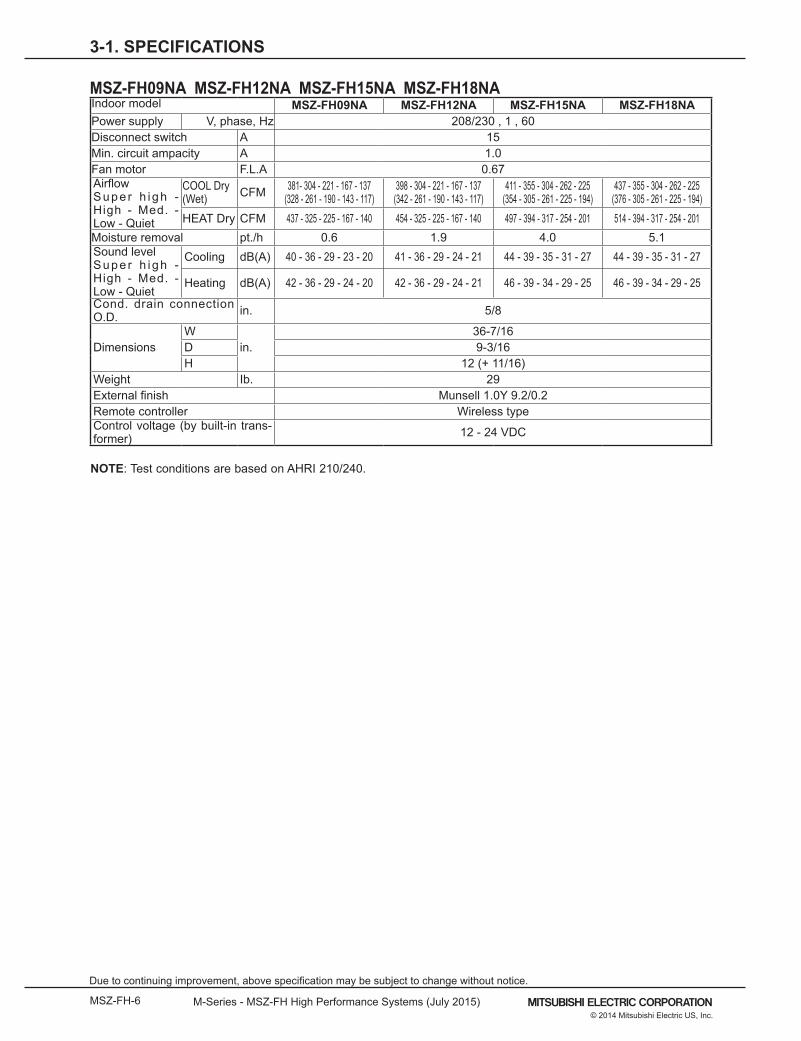
MSZ-FH09NA MSZ-FH12NA MSZ-FH15NA MSZ-FH18NAIndoor model MSZ-FH09NA MSZ-FH12NA MSZ-FH15NA MSZ-FH18NAPower supply V, phase, Hz 208/230 , 1 , 60Disconnect switch A 15Min. circuit ampacity A 1.0Fan motor F.L.A 0.67Airflow Supe r h i gh - High - Med. - Low - Quiet
COOL Dry (Wet) CFM 381- 304 - 221 - 167 - 137
(328 - 261 - 190 - 143 - 117)398 - 304 - 221 - 167 - 137
(342 - 261 - 190 - 143 - 117)411 - 355 - 304 - 262 - 225
(354 - 305 - 261 - 225 - 194)437 - 355 - 304 - 262 - 225
(376 - 305 - 261 - 225 - 194)HEAT Dry CFM 437 - 325 - 225 - 167 - 140 454 - 325 - 225 - 167 - 140 497 - 394 - 317 - 254 - 201 514 - 394 - 317 - 254 - 201
Moisture removal pt./h 0.6 1.9 4.0 5.1Sound level Supe r h i gh - High - Med. - Low - Quiet
Cooling dB(A) 40 - 36 - 29 - 23 - 20 41 - 36 - 29 - 24 - 21 44 - 39 - 35 - 31 - 27 44 - 39 - 35 - 31 - 27
Heating dB(A) 42 - 36 - 29 - 24 - 20 42 - 36 - 29 - 24 - 21 46 - 39 - 34 - 29 - 25 46 - 39 - 34 - 29 - 25
Cond. drain connection O.D. in. 5/8
DimensionsW
in.36-7/16
D 9-3/16H 12 (+ 11/16)
Weight Ib. 29External finish Munsell 1.0Y 9.2/0.2Remote controller Wireless typeControl voltage (by built-in trans-former) 12 - 24 VDC
NOTE: Test conditions are based on AHRI 210/240.
Page 7
M-Series - MSZ-FH High Performance Systems (July 2015) MSZ-FH-7© 2014 Mitsubishi Electric US, Inc.
Due to continuing improvement, above specification may be subject to change without notice.
3-1. SPECIFICATIONS
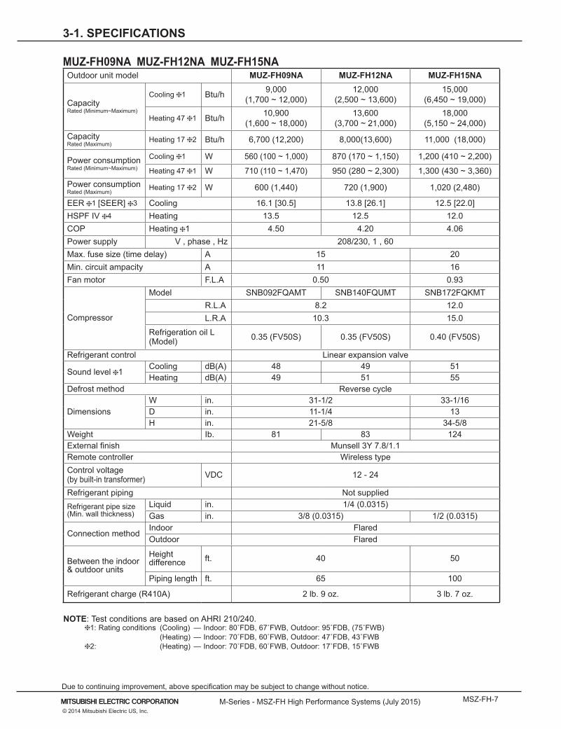
MUZ-FH09NA MUZ-FH12NA MUZ-FH15NAOutdoor unit model MUZ-FH09NA MUZ-FH12NA MUZ-FH15NA
Capacity Rated (Minimum~Maximum)
Cooling 1 Btu/h 9,000 (1,700 ~ 12,000)
12,000 (2,500 ~ 13,600)
15,000 (6,450 ~ 19,000)
Heating 47 1 Btu/h 10,900(1,600 ~ 18,000)
13,600 (3,700 ~ 21,000)
18,000 (5,150 ~ 24,000)
Capacity Rated (Maximum)
Heating 17 2 Btu/h 6,700 (12,200) 8,000(13,600) 11,000 (18,000)
Power consumption Rated (Minimum~Maximum)
Cooling 1 W 560 (100 ~ 1,000) 870 (170 ~ 1,150) 1,200 (410 ~ 2,200)
Heating 47 1 W 710 (110 ~ 1,470) 950 (280 ~ 2,300) 1,300 (430 ~ 3,360)Power consumption Rated (Maximum)
Heating 17 2 W 600 (1,440) 720 (1,900) 1,020 (2,480)
EER 1 [SEER] 3 Cooling 16.1 [30.5] 13.8 [26.1] 12.5 [22.0]HSPF IV 4 Heating 13.5 12.5 12.0COP Heating 1 4.50 4.20 4.06Power supply V , phase , Hz 208/230, 1 , 60Max. fuse size (time delay) A 15 20Min. circuit ampacity A 11 16Fan motor F.L.A 0.50 0.93
Compressor
Model SNB092FQAMT SNB140FQUMT SNB172FQKMTR.L.A 8.2 12.0L.R.A 10.3 15.0
Refrigeration oil L (Model) 0.35 (FV50S) 0.35 (FV50S) 0.40 (FV50S)
Refrigerant control Linear expansion valve
Sound level 1Cooling dB(A) 48 49 51Heating dB(A) 49 51 55
Defrost method Reverse cycle
Dimensions W in. 31-1/2 33-1/16D in. 11-1/4 13H in. 21-5/8 34-5/8
Weight Ib. 81 83 124External finish Munsell 3Y 7.8/1.1Remote controller Wireless typeControl voltage (by built-in transformer) VDC 12 - 24
Refrigerant piping Not suppliedRefrigerant pipe size (Min. wall thickness)
Liquid in. 1/4 (0.0315)Gas in. 3/8 (0.0315) 1/2 (0.0315)
Connection method Indoor FlaredOutdoor Flared
Between the indoor & outdoor units
Height difference ft. 40 50
Piping length ft. 65 100
Refrigerant charge (R410A) 2 lb. 9 oz. 3 lb. 7 oz.
NOTE: Test conditions are based on AHRI 210/240. 1: Rating conditions (Cooling) — Indoor: 80˚FDB, 67˚FWB, Outdoor: 95˚FDB, (75˚FWB) (Heating) — Indoor: 70˚FDB, 60˚FWB, Outdoor: 47˚FDB, 43˚FWB 2: (Heating) — Indoor: 70˚FDB, 60˚FWB, Outdoor: 17˚FDB, 15˚FWB
Page 8
MSZ-FH-8 M-Series - MSZ-FH High Performance Systems (July 2015)
Due to continuing improvement, above specification may be subject to change without notice.
© 2014 Mitsubishi Electric US, Inc.
3-1. SPECIFICATIONS
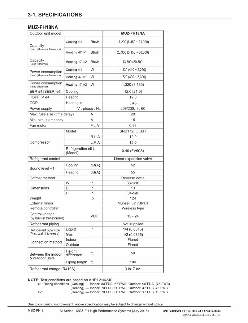
MUZ-FH18NAOutdoor unit model MUZ-FH18NA
Capacity Rated (Minimum~Maximum)
Cooling 1 Btu/h 17,200 (6,450 ~ 21,000)
Heating 47 1 Btu/h 20,300 (5,150 ~ 30,000)
Capacity Rated (Maximum)
Heating 17 2 Btu/h 13,700 (20,300)
Power consumption Rated (Minimum~Maximum)
Cooling 1 W 1,430 (410 ~ 2,220)
Heating 47 1 W 1,720 (430 ~ 3,390)
Power consumption Rated (Maximum)
Heating 17 2 W 1,320 (3,180)
EER 1 [SEER] 3 Cooling 12.0 [21.0]HSPF IV 4 Heating 12.0COP Heating 1 3.46Power supply V , phase , Hz 208/230, 1 , 60Max. fuse size (time delay) A 20Min. circuit ampacity A 16Fan motor F.L.A 0.93
Compressor
Model SNB172FQKMTR.L.A 12.0L.R.A 15.0
Refrigeration oil L (Model) 0.40 (FV50S)
Refrigerant control Linear expansion valve
Sound level 1Cooling dB(A) 52
Heating dB(A) 55Defrost method Reverse cycle
Dimensions W in. 33-1/16D in. 13H in. 34-5/8
Weight Ib. 124External finish Munsell 3Y 7.8/1.1Remote controller Wireless typeControl voltage (by built-in transformer) VDC 12 - 24
Refrigerant piping Not suppliedRefrigerant pipe size (Min. wall thickness)
Liquid in. 1/4 (0.0315)Gas in. 1/2 (0.0315)
Connection method Indoor FlaredOutdoor Flared
Between the indoor & outdoor units
Height difference ft. 50
Piping length ft. 100
Refrigerant charge (R410A) 3 lb. 7 oz.
NOTE: Test conditions are based on AHRI 210/240. 1: Rating conditions (Cooling) — Indoor: 80˚FDB, 67˚FWB, Outdoor: 95˚FDB, (75˚FWB) (Heating) — Indoor: 70˚FDB, 60˚FWB, Outdoor: 47˚FDB, 43˚FWB 2: (Heating) — Indoor: 70˚FDB, 60˚FWB, Outdoor: 17˚FDB, 15˚FWB
Page 9
M-Series - MSZ-FH High Performance Systems (July 2015) MSZ-FH-9© 2014 Mitsubishi Electric US, Inc.
Due to continuing improvement, above specification may be subject to change without notice.
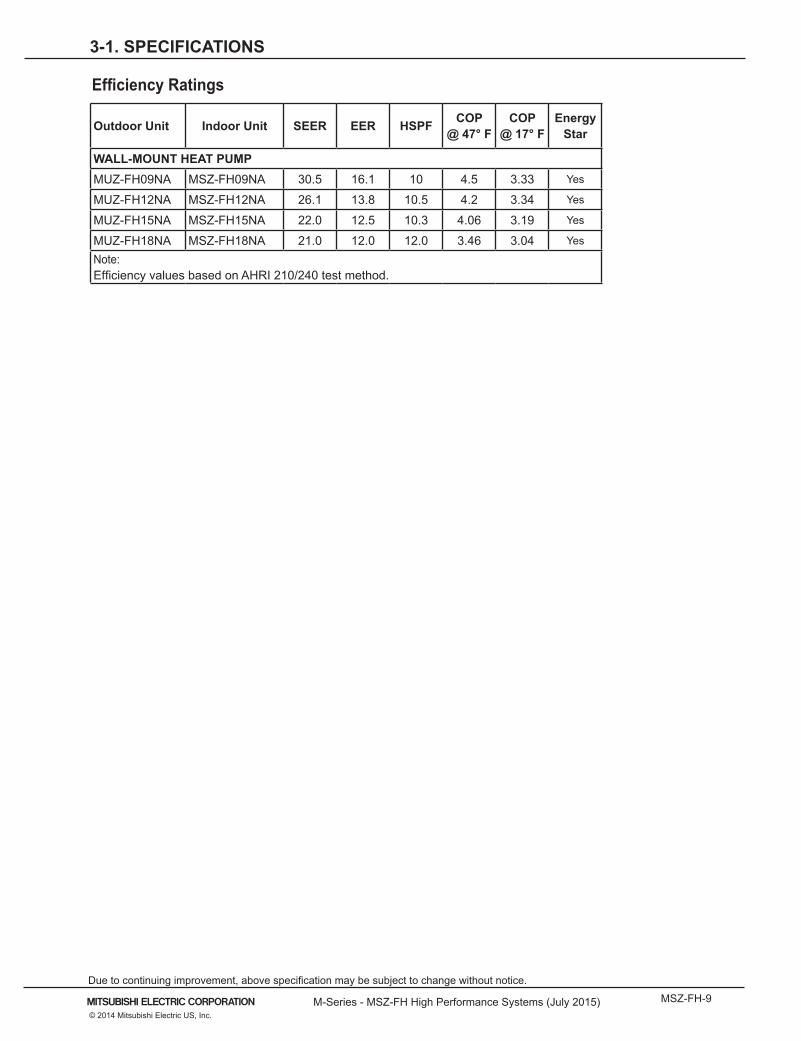
Efficiency Ratings
Outdoor Unit Indoor Unit SEER EER HSPF COP @ 47° F
COP @ 17° F
Energy Star
WALL-MOUNT HEAT PUMPMUZ-FH09NA MSZ-FH09NA 30.5 16.1 10 4.5 3.33 Yes
MUZ-FH12NA MSZ-FH12NA 26.1 13.8 10.5 4.2 3.34 Yes
MUZ-FH15NA MSZ-FH15NA 22.0 12.5 10.3 4.06 3.19 Yes
MUZ-FH18NA MSZ-FH18NA 21.0 12.0 12.0 3.46 3.04 Yes
Note:Efficiency values based on AHRI 210/240 test method.
3-1. SPECIFICATIONS
Page 10
MSZ-FH-10 M-Series - MSZ-FH High Performance Systems (July 2015)
Due to continuing improvement, above specification may be subject to change without notice.
© 2014 Mitsubishi Electric US, Inc.
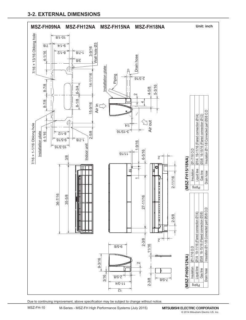
3-2. EXTERNAL DIMENSIONS
MSZ-FH09NA MSZ-FH12NA MSZ-FH15NA MSZ-FH18NA Unit: inch
2-3/
8 7-5/8
11/1
6
4-1/
16
6-3/
48-
1/8
4-1/
16
10-3/16
9-5/16
8-1/2
1-7/8 2-5/
815
-9/1
614
-11/
163-
9/16
3/8
1-7/88-1/2
10-1/8
7/8
8-7/
88-
7/8
36-7
/16
35-5
/83/
8
9-1/4
4
4-5/
8
1/4
3-15/16
2
2-3/16
5-3/
16
2-5/
82-
11/1
6
2
2
3/16
9-3/
16 2
2-5/8
11-3/4
12
9-5/8 2-3/
827
-11/
166-
5/16
1-9/
161
11/16
Piping
Insu
lation
Ø1-7
/16
O.D
Liquid
line
Ø1/4
19-
11/1
6 (F
lared
conn
ectio
n Ø1
/4)
Gas l
ineØ3
/8 1
6-15
/16
(Flar
ed co
nnec
tion
Ø3/8
)Dr
ain h
ose
Insu
lation
Ø1-
1/8
Conn
ecte
d pa
rt Ø5
/8 O
.D
Piping
Insu
lation
Ø1-7
/16
O.D
Liquid
line
Ø1/4
19-
11/1
6 (F
lared
conn
ectio
n Ø1
/4)
Gas l
ineØ3
/8 1
6-15
/16
(Flar
ed co
nnec
tion
Ø1/2
)Dr
ain h
ose
Insu
lation
Ø1-
1/8
Conn
ecte
d pa
rt Ø5
/8 O
.D
Pip
ing
Dra
in h
ose
Inst
alla
tion
plat
e
Indo
or u
nit
7/16
× 1
3/16
Obl
ong
hole
Inst
alla
tion
plat
e
7/16
× 1
-1/1
6 O
blon
g ho
le
Wal
l hol
e Ø
3A
ir in
Air
out
(MSZ
-FH
09/1
2NA
)(M
SZ-F
H15
/18N
A)
Page 11
M-Series - MSZ-FH High Performance Systems (July 2015) MSZ-FH-11© 2014 Mitsubishi Electric US, Inc.
Due to continuing improvement, above specification may be subject to change without notice.
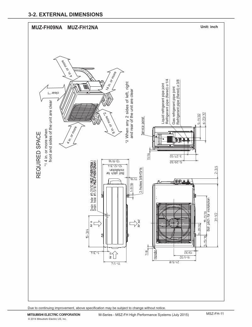
3-2. EXTERNAL DIMENSIONS
MUZ-FH09NA MUZ-FH12NA Unit: inch
clear *1
*1 4
in. o
r mor
e w
hen
front
and
sid
es o
f the
uni
t are
cle
ar
*2 W
hen
any
2 si
des
of le
ft, r
ight
an
d re
ar o
f the
uni
t are
cle
ar
hole
s
REQ
UIR
ED S
PAC
E
Liqu
id re
frige
rant
pip
e jo
int
Ref
riger
ant p
ipe
(flar
ed) Ø
1/4
Gas
refri
gera
nt p
ipe
join
tR
efrig
eran
t pip
e (fl
ared
) Ø 3
/8
4 in
. or m
ore
14 in
. or m
ore
8 in
. or m
ore
*2
4 in
. or m
ore
Page 12
MSZ-FH-12 M-Series - MSZ-FH High Performance Systems (July 2015)
Due to continuing improvement, above specification may be subject to change without notice.
© 2014 Mitsubishi Electric US, Inc.
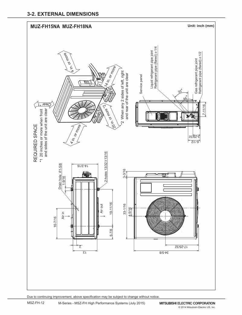
3-2. EXTERNAL DIMENSIONS
MUZ-FH15NA MUZ-FH18NA Unit: inch (mm)
16-7
/16
1-9/
161-
5/8
Dra
in h
ole
6-7/
819
-11/
16
13
2A
ir in A
ir ou
t2-
hole
s 13
/32
13/
16
14-3/16
33-1
/16
4-5/
16
3-3/
16
34-5/8
17-25/32
Ser
vice
pan
el
3-29/326-1/2
7-11
/16
35
44
Liqu
id re
frige
rant
pip
e jo
int
Ref
riger
ant p
ipe
(flar
ed) Ø
1/4
Gas
refri
gera
nt p
ipe
join
tR
efrig
eran
t pip
e (fl
ared
) Ø 1
/2
14 in
. or m
ore
4 in
. or m
ore
REQ
UIR
ED S
PAC
E
4 in
. or m
ore
20 in
. or m
ore
*2
*1 2
0 in
ches
or m
ore
whe
n fro
nt
and
side
s of
the
unit
are
clea
r
*2 W
hen
any
2 si
des
of le
ft, ri
ght
an
d re
ar o
f the
uni
t are
cle
ar
Clear *1
Page 13
M-Series - MSZ-FH High Performance Systems (July 2015) MSZ-FH-13© 2014 Mitsubishi Electric US, Inc.
Due to continuing improvement, above specification may be subject to change without notice.
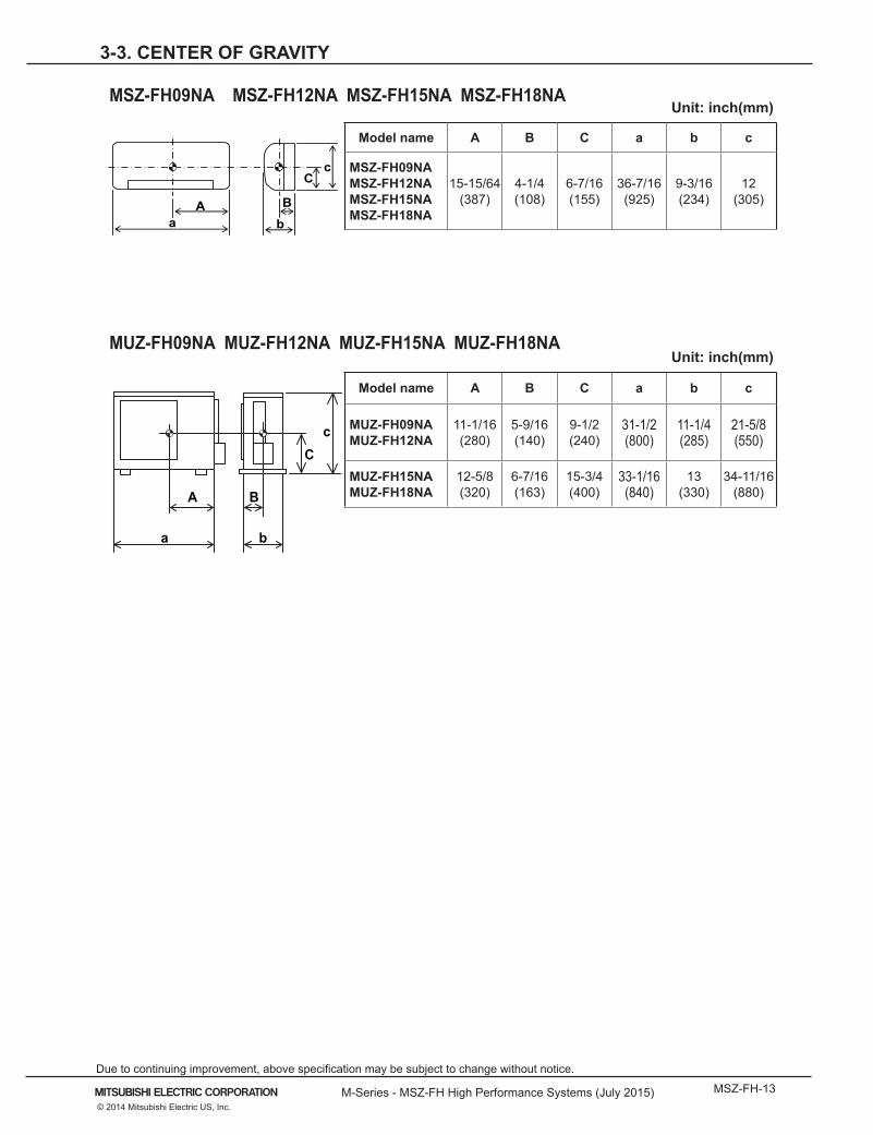
3-3. CENTER OF GRAVITY
cC
A
a b
B
a bB
cC
A
Unit: inch(mm)
Model name A B C a b c
MSZ-FH09NAMSZ-FH12NAMSZ-FH15NAMSZ-FH18NA
15-15/64(387)
4-1/4(108)
6-7/16(155)
36-7/16(925)
9-3/16(234)
12(305)
Unit: inch(mm)
Model name A B C a b c
MUZ-FH09NAMUZ-FH12NA
11-1/16(280)
5-9/16(140)
9-1/2(240)
31-1/2(800)
11-1/4(285)
21-5/8(550)
MUZ-FH15NAMUZ-FH18NA
12-5/8(320)
6-7/16(163)
15-3/4(400)
33-1/16(840)
13(330)
34-11/16(880)
MUZ-FH09NA MUZ-FH12NA MUZ-FH15NA MUZ-FH18NA
MSZ-FH09NA MSZ-FH12NA MSZ-FH15NA MSZ-FH18NA
Page 14
MSZ-FH-14 M-Series - MSZ-FH High Performance Systems (July 2015)
Due to continuing improvement, above specification may be subject to change without notice.
© 2014 Mitsubishi Electric US, Inc.
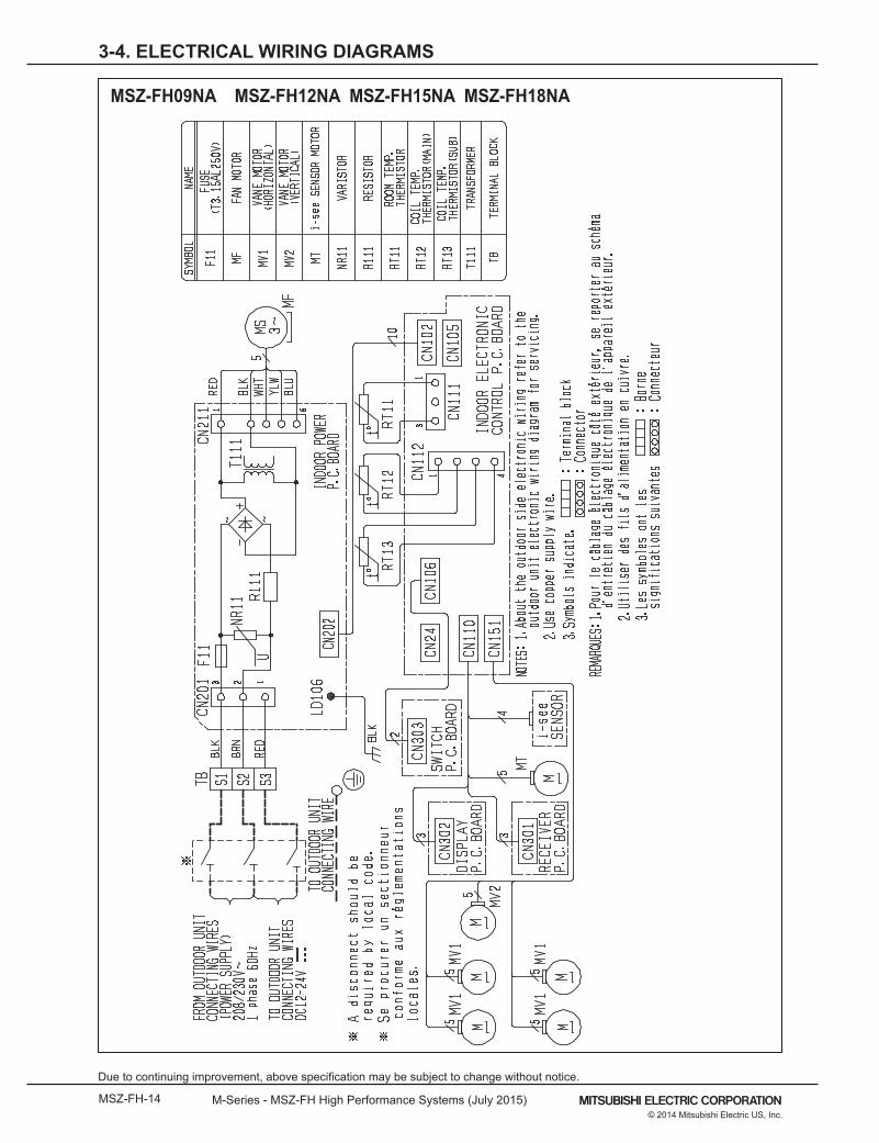
3-4. ELECTRICAL WIRING DIAGRAMS
MSZ-FH09NA MSZ-FH12NA MSZ-FH15NA MSZ-FH18NA
Page 15
M-Series - MSZ-FH High Performance Systems (July 2015) MSZ-FH-15© 2014 Mitsubishi Electric US, Inc.
Due to continuing improvement, above specification may be subject to change without notice.
3-4. ELECTRICAL WIRING DIAGRAMS
MUZ-FH09NA MUZ-FH12NA
Page 16
MSZ-FH-16 M-Series - MSZ-FH High Performance Systems (July 2015)
Due to continuing improvement, above specification may be subject to change without notice.
© 2014 Mitsubishi Electric US, Inc.
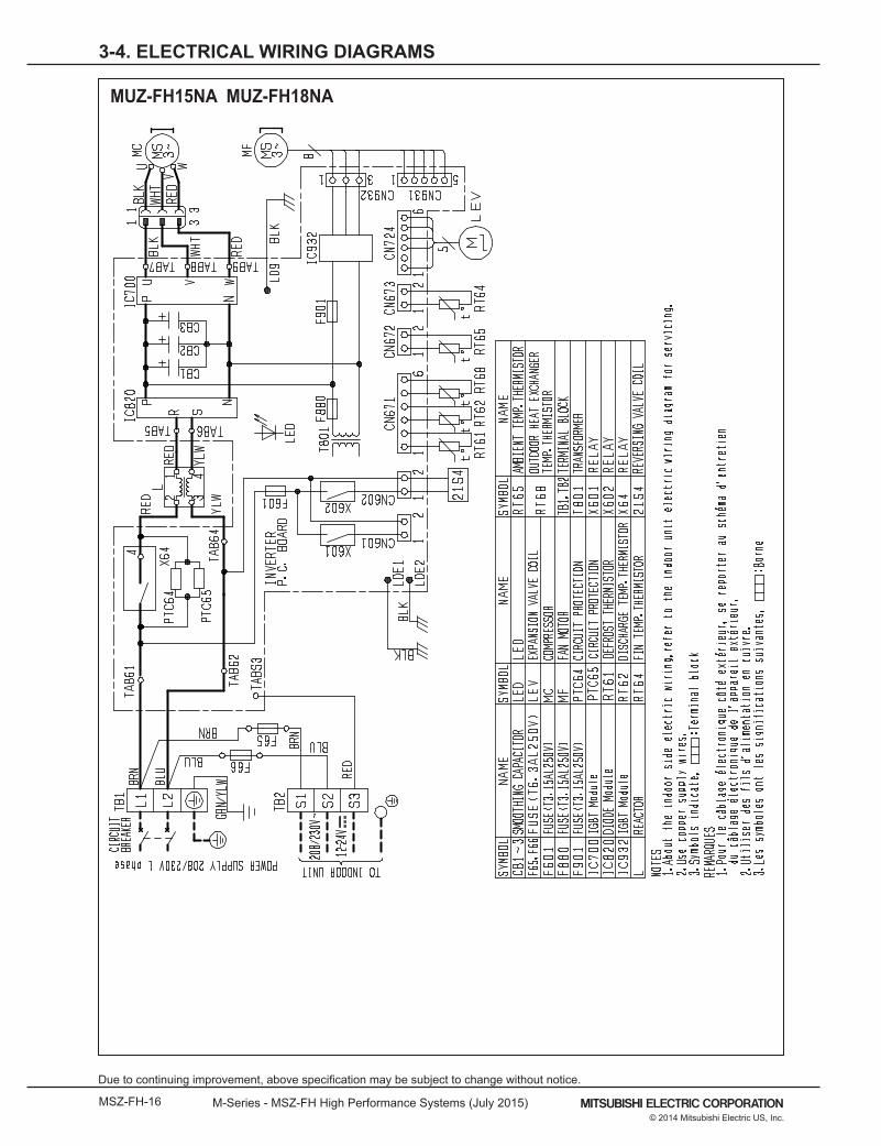
3-4. ELECTRICAL WIRING DIAGRAMS
MUZ-FH15NA MUZ-FH18NA
Page 17
M-Series - MSZ-FH High Performance Systems (July 2015) MSZ-FH-17© 2014 Mitsubishi Electric US, Inc.
Due to continuing improvement, above specification may be subject to change without notice.
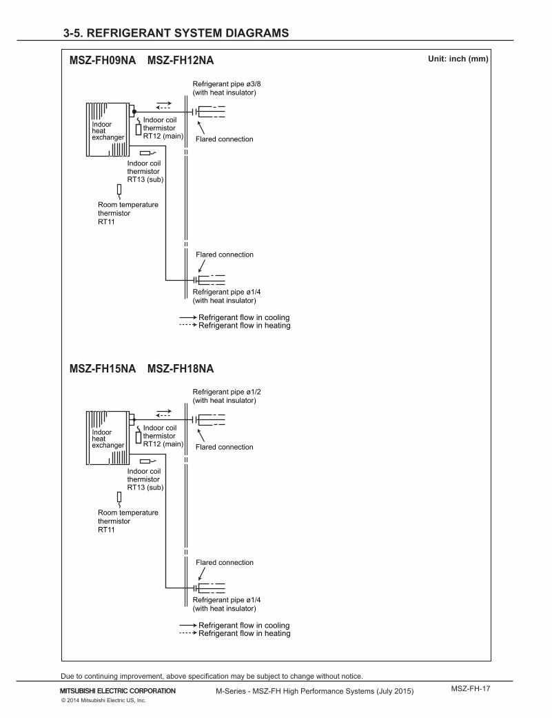
3-5. REFRIGERANT SYSTEM DIAGRAMS
Unit: inch (mm)MSZ-FH09NA MSZ-FH12NA
MSZ-FH15NA MSZ-FH18NA
Indoorheatexchanger Flared connection
Room temperaturethermistorRT11
Flared connection
Refrigerant pipe ø3/8(with heat insulator)
Refrigerant pipe ø1/4(with heat insulator)
Indoor coil thermistorRT12 (main)
Indoor coil thermistorRT13 (sub)
Refrigerant flow in coolingRefrigerant flow in heating
Indoorheatexchanger Flared connection
Room temperaturethermistorRT11
Flared connection
Refrigerant pipe ø1/2(with heat insulator)
Refrigerant pipe ø1/4(with heat insulator)
Indoor coil thermistorRT12 (main)
Indoor coil thermistorRT13 (sub)
Refrigerant flow in coolingRefrigerant flow in heating
Page 18
MSZ-FH-18 M-Series - MSZ-FH High Performance Systems (July 2015)
Due to continuing improvement, above specification may be subject to change without notice.
© 2014 Mitsubishi Electric US, Inc.
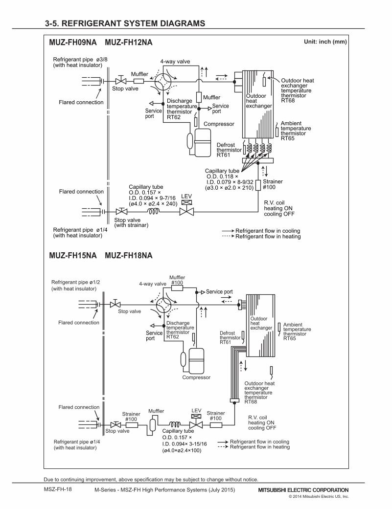
3-5. REFRIGERANT SYSTEM DIAGRAMS
Unit: inch (mm)MUZ-FH09NA MUZ-FH12NA
MUZ-FH15NA MUZ-FH18NA
Outdoorheatexchanger
Flared connection
DefrostthermistorRT61
DischargetemperaturethermistorRT62
Flared connection
Stop valve
Stop valve
Capillary tubeO.D. 0.157 × I.D. 0.094× 3-15/16(ø4.0×ø2.4×100)
Refrigerant flow in cooling
Compressor
Service port4-way valve
Refrigerant flow in heating
Refrigerant pipe ø1/2(with heat insulator)
Refrigerant pipe ø1/4(with heat insulator)
LEVMufflerR.V. coilheating ONcooling OFF
Muffler#100
Strainer#100
Outdoor heat exchanger temperaturethermistorRT68
AmbienttemperaturethermistorRT65
Strainer#100
Serviceport
OutdoorheatexchangerFlared connection
DefrostthermistorRT61
DischargetemperaturethermistorRT62
Flared connection
Stop valve(with strainar)
Stop valve
Refrigerant flow in cooling
Compressor
4-way valve
Refrigerant flow in heating
Refrigerant pipe ø3/8(with heat insulator)
Refrigerant pipe ø1/4(with heat insulator)
R.V. coilheating ONcooling OFF
Strainer#100
LEV
Ambient temperature thermistorRT65
Muffler
Capillary tubeO.D. 0.157 × I.D. 0.094 × 9-7/16(ø4.0 × ø2.4 × 240)
Outdoor heatexchangertemperature thermistorRT68
Capillary tube O.D. 0.118 × I.D. 0.079 × 8-9/32(ø3.0 × ø2.0 × 210)
ServiceportService
port
Muffler
Page 19
M-Series - MSZ-FH High Performance Systems (July 2015) MSZ-FH-19© 2014 Mitsubishi Electric US, Inc.
Due to continuing improvement, above specification may be subject to change without notice.
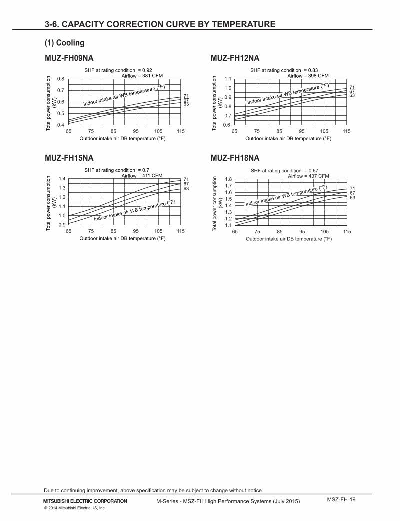
3-6. CAPACITY CORRECTION CURVE BY TEMPERATURE
(1) Cooling
716763
65 75 85 95 105 1150.4
0.5
0.6
0.7
0.8
Indoor intake air WB temperature (°F)
SHF at rating condition = 0.92= 381 CFMAirflow
Outdoor intake air DB temperature (°F)
Tota
l pow
er c
onsu
mpt
ion
(kW
)
716763
65 75 85 95 105 1150.6
0.7
0.8
0.9
1.0
1.1
Indoor intake air WB temperature (°F)
SHF at rating condition = 0.83= 398 CFMAirflow
Outdoor intake air DB temperature (°F)
Tota
l pow
er c
onsu
mpt
ion
(kW
)
MUZ-FH09NA MUZ-FH12NA
MUZ-FH15NA MUZ-FH18NA
716763
65 75 85 95 105 1150.9
1.0
1.1
1.2
1.3
1.4
Indoor intake air WB temperature (°F)
SHF at rating condition = 0.7= 411 CFMAirflow
Outdoor intake air DB temperature (°F)
Tota
l pow
er c
onsu
mpt
ion
(kW
)
716763
65 75 85 95 105 1151.11.21.31.41.51.61.71.8
Indoor intake air WB temperature (°F)
SHF at rating condition = 0.67= 437 CFMAirflow
Outdoor intake air DB temperature (°F)
Tota
l pow
er c
onsu
mpt
ion
(kW
)
Page 20
MSZ-FH-20 M-Series - MSZ-FH High Performance Systems (July 2015)
Due to continuing improvement, above specification may be subject to change without notice.
© 2014 Mitsubishi Electric US, Inc.
3-6. CAPACITY CORRECTION CURVE BY TEMPERATURE
(2) Heating
657075
-5 5 15 25 35 45 55 650.2
0.4
0.6
0.8
Indoor intake air DB temperature (°F)
= 437 CFMAirflow
Outdoor intake air WB temperature (°F)
Tota
l pow
er c
onsu
mpt
ion
(kW
)
657075
-5 5 15 25 35 45 55 650.3
0.6
0.9
1.2
Indoor intake air DB temperature (°F)
= 454 CFMAirflow
Outdoor intake air WB temperature (°F)
Tota
l pow
er c
onsu
mpt
ion
(kW
)
MUZ-FH15NA
MUZ-FH18NA
657075
-5 5 15 25 35 45 55 650.50
0.75
1.00
1.25
1.50
Indoor intake air DB temperature (°F)
= 454 CFMAirflow
Outdoor intake air WB temperature (°F)
Tota
l pow
er c
onsu
mpt
ion
(kW
)
657075
-5 5 15 25 35 45 55 650.50
0.75
1.00
1.25
1.50
1.75
2.00
Indoor intake air DB temperature (°F)
= 514 CFMAirflow
Outdoor intake air WB temperature (°F)
Tota
l pow
er c
onsu
mpt
ion
(kW
)MUZ-FH09NA
MUZ-FH12NA
Page 21
M-Series - MSZ-FH High Performance Systems (July 2015) MSZ-FH-21© 2014 Mitsubishi Electric US, Inc.
Due to continuing improvement, above specification may be subject to change without notice.
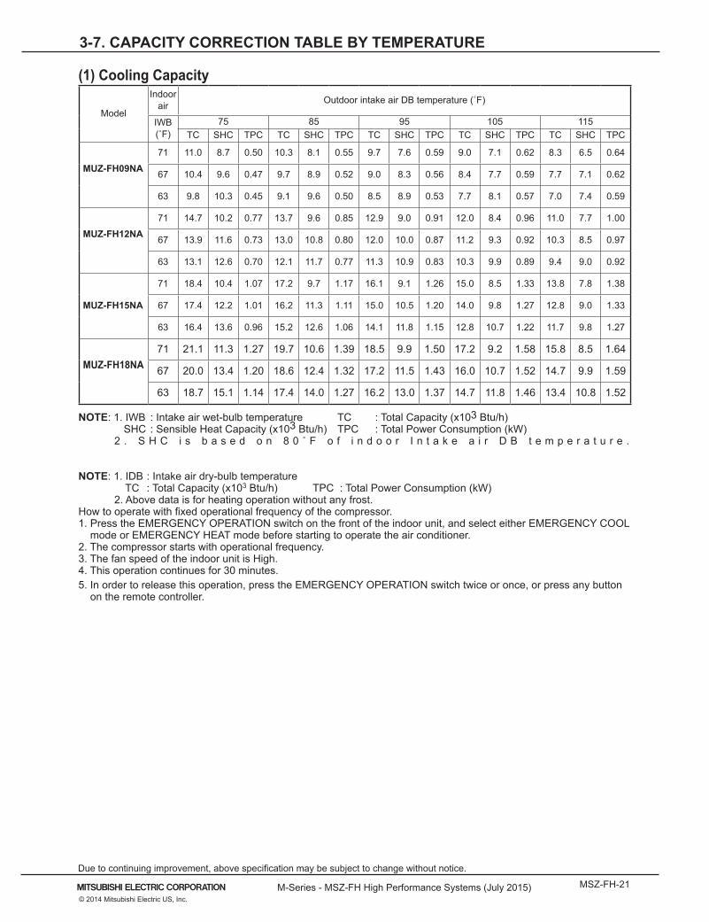
3-7. CAPACITY CORRECTION TABLE BY TEMPERATURE
(1) Cooling Capacity
Model
Indoor air Outdoor intake air DB temperature (˚F)
IWB (˚F)
75 85 95 105 115TC SHC TPC TC SHC TPC TC SHC TPC TC SHC TPC TC SHC TPC
MUZ-FH09NA71 11.0 8.7 0.50 10.3 8.1 0.55 9.7 7.6 0.59 9.0 7.1 0.62 8.3 6.5 0.64
67 10.4 9.6 0.47 9.7 8.9 0.52 9.0 8.3 0.56 8.4 7.7 0.59 7.7 7.1 0.62
63 9.8 10.3 0.45 9.1 9.6 0.50 8.5 8.9 0.53 7.7 8.1 0.57 7.0 7.4 0.59
MUZ-FH12NA71 14.7 10.2 0.77 13.7 9.6 0.85 12.9 9.0 0.91 12.0 8.4 0.96 11.0 7.7 1.00
67 13.9 11.6 0.73 13.0 10.8 0.80 12.0 10.0 0.87 11.2 9.3 0.92 10.3 8.5 0.97
63 13.1 12.6 0.70 12.1 11.7 0.77 11.3 10.9 0.83 10.3 9.9 0.89 9.4 9.0 0.92
MUZ-FH15NA
71 18.4 10.4 1.07 17.2 9.7 1.17 16.1 9.1 1.26 15.0 8.5 1.33 13.8 7.8 1.38
67 17.4 12.2 1.01 16.2 11.3 1.11 15.0 10.5 1.20 14.0 9.8 1.27 12.8 9.0 1.33
63 16.4 13.6 0.96 15.2 12.6 1.06 14.1 11.8 1.15 12.8 10.7 1.22 11.7 9.8 1.27
MUZ-FH18NA71 21.1 11.3 1.27 19.7 10.6 1.39 18.5 9.9 1.50 17.2 9.2 1.58 15.8 8.5 1.64
67 20.0 13.4 1.20 18.6 12.4 1.32 17.2 11.5 1.43 16.0 10.7 1.52 14.7 9.9 1.59
63 18.7 15.1 1.14 17.4 14.0 1.27 16.2 13.0 1.37 14.7 11.8 1.46 13.4 10.8 1.52
NOTE: 1. IWB : Intake air wet-bulb temperature TC : Total Capacity (x103 Btu/h)SHC : Sensible Heat Capacity (x103 Btu/h) TPC : Total Power Consumption (kW)
2 . S H C i s b a s e d o n 8 0 ˚ F o f i n d o o r I n t a k e a i r D B t e m p e r a t u r e .
NOTE: 1. IDB : Intake air dry-bulb temperatureTC : Total Capacity (x103 Btu/h) TPC : Total Power Consumption (kW)
2. Above data is for heating operation without any frost.How to operate with fixed operational frequency of the compressor.1. Press the EMERGENCY OPERATION switch on the front of the indoor unit, and select either EMERGENCY COOL
mode or EMERGENCY HEAT mode before starting to operate the air conditioner.2. The compressor starts with operational frequency.3. The fan speed of the indoor unit is High.4. This operation continues for 30 minutes.5. In order to release this operation, press the EMERGENCY OPERATION switch twice or once, or press any button
on the remote controller.
Page 22
MSZ-FH-22 M-Series - MSZ-FH High Performance Systems (July 2015)
Due to continuing improvement, above specification may be subject to change without notice.
© 2014 Mitsubishi Electric US, Inc.
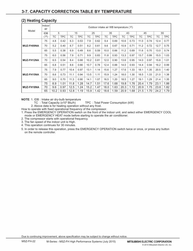
3-7. CAPACITY CORRECTION TABLE BY TEMPERATURE
(2) Heating Capacity
Model
Indoor air Outdoor intake air WB temperature (˚F)
IDB (˚F)
5 15 25 35 43 45 55TC TPC TC TPC TC TPC TC TPC TC TPC TC TPC TC TPC
MUZ-FH09NA
75 4.8 0.42 6.3 0.53 7.9 0.62 9.4 0.69 10.6 0.73 11.0 0.74 12.4 0.77
70 5.2 0.40 6.7 0.51 8.2 0.61 9.6 0.67 10.9 0.71 11.2 0.72 12.7 0.75
65 5.5 0.38 6.9 0.49 8.6 0.59 10.0 0.66 11.2 0.69 11.6 0.70 13.0 0.74
MUZ-FH12NA
75 6.0 0.56 7.9 0.71 9.9 0.83 11.8 0.93 13.3 0.97 13.7 0.99 15.5 1.03
70 6.5 0.54 8.4 0.68 10.2 0.81 12.0 0.90 13.6 0.95 14.0 0.97 15.8 1.01
65 6.8 0.51 8.6 0.66 10.7 0.78 12.4 0.88 14.0 0.93 14.4 0.94 16.2 0.99
MUZ-FH15NA
75 7.9 0.77 10.4 0.97 13.1 1.14 15.6 1.27 17.6 1.33 18.1 1.35 20.5 1.40
70 8.6 0.73 11.1 0.94 13.5 1.11 15.9 1.24 18.0 1.30 18.5 1.33 21.0 1.38
65 9.0 0.70 11.3 0.90 14.1 1.07 16.5 1.20 18.5 1.27 19.1 1.29 21.4 1.35
MUZ-FH18NA75 8.9 1.01 11.8 1.28 14.7 1.51 17.6 1.68 19.8 1.76 20.4 1.79 23.1 1.8670 9.6 0.97 12.5 1.24 15.2 1.47 18.0 1.63 20.3 1.72 20.9 1.75 23.6 1.8265 10.2 0.93 12.8 1.19 15.9 1.42 18.6 1.59 20.9 1.68 21.5 1.70 24.2 1.79
NOTE: 1. IDB : Intake air dry-bulb temperature
TC : Total Capacity (x103 Btu/h) TPC : Total Power Consumption (kW)2. Above data is for heating operation without any frost.
How to operate with fixed operational frequency of the compressor.1. Press the EMERGENCY OPERATION switch on the front of the indoor unit, and select either EMERGENCY COOL
mode or EMERGENCY HEAT mode before starting to operate the air conditioner.2. The compressor starts with operational frequency.3. The fan speed of the indoor unit is High.4. This operation continues for 30 minutes.5. In order to release this operation, press the EMERGENCY OPERATION switch twice or once, or press any button
on the remote controller.
Page 23
M-Series - MSZ-FH High Performance Systems (July 2015) MSZ-FH-23© 2014 Mitsubishi Electric US, Inc.
Due to continuing improvement, above specification may be subject to change without notice.
70 77 81 86 95 104 11560 1.11 1.06 1.01 0.97 0.91 0.83 0.76
63 1.16 1.10 1.06 1.02 0.96 0.88 0.81
64 1.18 1.13 1.08 1.04 0.98 0.90 0.83
68 1.23 1.18 1.14 1.10 1.03 0.96 0.89
72 1.28 1.23 1.20 1.15 1.09 1.02 0.95
75 1.34 1.29 1.26 1.22 1.15 1.08 1.02
79 1.38 1.34 1.32 1.28 1.21 1.14 1.07
(3) M-Series Cooling Correction
Outdoor intake
temperature W.B. [° F]
43 39 36 32 28 25 21 18 14
Outdoor intake
temperature W.B. [° C]
6 4 2 0 -2 -4 -6 -8 -10
Correction factor 1.00 0.80 0.82 0.84 0.87 0.90 0.93 0.96 1.00
(4) M-Series Defrost Correction
3-7. CAPACITY CORRECTION TABLE BY TEMPERATURE
Page 24
MSZ-FH-24 M-Series - MSZ-FH High Performance Systems (July 2015)
Due to continuing improvement, above specification may be subject to change without notice.
© 2014 Mitsubishi Electric US, Inc.
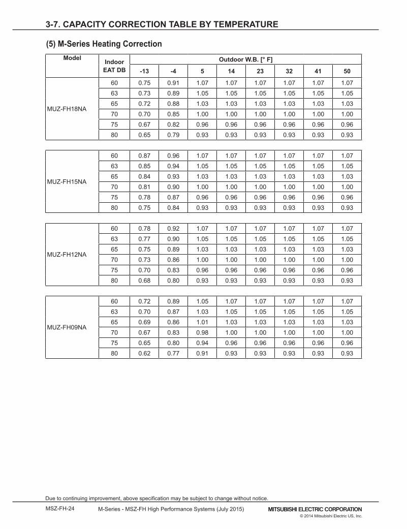
(5) M-Series Heating CorrectionModel Indoor
EAT DBOutdoor W.B. [° F]
-13 -4 5 14 23 32 41 50
MUZ-FH18NA
60 0.75 0.91 1.07 1.07 1.07 1.07 1.07 1.07
63 0.73 0.89 1.05 1.05 1.05 1.05 1.05 1.05
65 0.72 0.88 1.03 1.03 1.03 1.03 1.03 1.03
70 0.70 0.85 1.00 1.00 1.00 1.00 1.00 1.00
75 0.67 0.82 0.96 0.96 0.96 0.96 0.96 0.96
80 0.65 0.79 0.93 0.93 0.93 0.93 0.93 0.93
MUZ-FH15NA
60 0.87 0.96 1.07 1.07 1.07 1.07 1.07 1.07
63 0.85 0.94 1.05 1.05 1.05 1.05 1.05 1.05
65 0.84 0.93 1.03 1.03 1.03 1.03 1.03 1.03
70 0.81 0.90 1.00 1.00 1.00 1.00 1.00 1.00
75 0.78 0.87 0.96 0.96 0.96 0.96 0.96 0.96
80 0.75 0.84 0.93 0.93 0.93 0.93 0.93 0.93
MUZ-FH12NA
60 0.78 0.92 1.07 1.07 1.07 1.07 1.07 1.07
63 0.77 0.90 1.05 1.05 1.05 1.05 1.05 1.05
65 0.75 0.89 1.03 1.03 1.03 1.03 1.03 1.03
70 0.73 0.86 1.00 1.00 1.00 1.00 1.00 1.00
75 0.70 0.83 0.96 0.96 0.96 0.96 0.96 0.96
80 0.68 0.80 0.93 0.93 0.93 0.93 0.93 0.93
MUZ-FH09NA
60 0.72 0.89 1.05 1.07 1.07 1.07 1.07 1.07
63 0.70 0.87 1.03 1.05 1.05 1.05 1.05 1.05
65 0.69 0.86 1.01 1.03 1.03 1.03 1.03 1.03
70 0.67 0.83 0.98 1.00 1.00 1.00 1.00 1.00
75 0.65 0.80 0.94 0.96 0.96 0.96 0.96 0.96
80 0.62 0.77 0.91 0.93 0.93 0.93 0.93 0.93
3-7. CAPACITY CORRECTION TABLE BY TEMPERATURE
Page 25
M-Series - MSZ-FH High Performance Systems (July 2015) MSZ-FH-25© 2014 Mitsubishi Electric US, Inc.
Due to continuing improvement, above specification may be subject to change without notice.
Indoor EAT DB Model
Outdoor W.B. [°F]-13 -4 5 14 23 32 41 50
60
MUZ-FH09NA 0.75 0.91 1.07 1.07 1.07 1.07 1.07 1.07
MUZ-FH12NA 0.87 0.96 1.07 1.07 1.07 1.07 1.07 1.07
MUZ-FH15NA 0.78 0.92 1.07 1.07 1.07 1.07 1.07 1.07MUZ-FH18NA 0.72 0.89 1.05 1.07 1.07 1.07 1.07 1.07
63
MUZ-FH09NA 0.73 0.89 1.05 1.05 1.05 1.05 1.05 1.05
MUZ-FH12NA 0.85 0.94 1.05 1.05 1.05 1.05 1.05 1.05
MUZ-FH15NA 0.77 0.90 1.05 1.05 1.05 1.05 1.05 1.05MUZ-FH18NA 0.70 0.87 1.03 1.05 1.05 1.05 1.05 1.05
65
MUZ-FH09NA 0.72 0.88 1.03 1.03 1.03 1.03 1.03 1.03
MUZ-FH12NA 0.84 0.93 1.03 1.03 1.03 1.03 1.03 1.03
MUZ-FH15NA 0.75 0.89 1.03 1.03 1.03 1.03 1.03 1.03MUZ-FH18NA 0.69 0.86 1.01 1.03 1.03 1.03 1.03 1.03
70
MUZ-FH09NA 0.70 0.85 1.00 1.00 1.00 1.00 1.00 1.00
MUZ-FH12NA 0.81 0.90 1.00 1.00 1.00 1.00 1.00 1.00
MUZ-FH15NA 0.73 0.86 1.00 1.00 1.00 1.00 1.00 1.00MUZ-FH18NA 0.67 0.83 0.98 1.00 1.00 1.00 1.00 1.00
75
MUZ-FH09NA 0.67 0.82 0.96 0.96 0.96 0.96 0.96 0.96
MUZ-FH12NA 0.78 0.87 0.96 0.96 0.96 0.96 0.96 0.96
MUZ-FH15NA 0.70 0.83 0.96 0.96 0.96 0.96 0.96 0.96
MUZ-FH18NA 0.65 0.80 0.94 0.96 0.96 0.96 0.96 0.96
80
MUZ-FH09NA 0.65 0.79 0.93 0.93 0.93 0.93 0.93 0.93
MUZ-FH12NA 0.75 0.84 0.93 0.93 0.93 0.93 0.93 0.93
MUZ-FH15NA 0.68 0.80 0.93 0.93 0.93 0.93 0.93 0.93
MUZ-FH18NA 0.62 0.77 0.91 0.93 0.93 0.93 0.93 0.93
3-7. CAPACITY CORRECTION TABLE BY TEMPERATURE
(5) M-Series Heating Correction cont.
Page 26
MSZ-FH-26 M-Series - MSZ-FH High Performance Systems (July 2015)
Due to continuing improvement, above specification may be subject to change without notice.
© 2014 Mitsubishi Electric US, Inc.
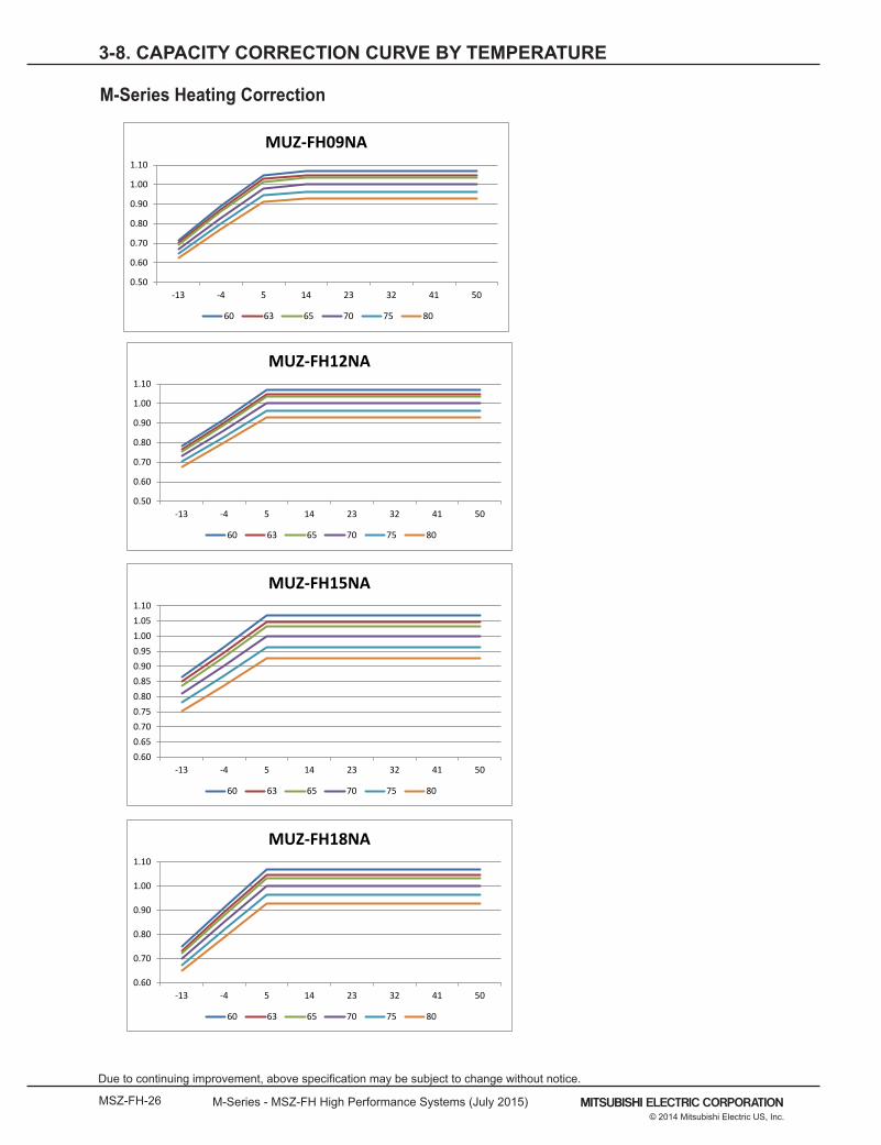
3-8. CAPACITY CORRECTION CURVE BY TEMPERATURE
Correction FactorsBelow 70 1.034025
Above 70 0.963249
0.60 0.65 0.70 0.75 0.80 0.85 0.90 0.95 1.00 1.05 1.10
-13 -4 5 14 23 32 41 50
MUZ-FH15NA
60 63 65 70 75 80
0.50
0.60
0.70
0.80
0.90
1.00
1.10
-13 -4 5 14 23 32 41 50
MUZ-FH12NA
60 63 65 70 75 80
0.50
0.60
0.70
0.80
0.90
1.00
1.10
-13 -4 5 14 23 32 41 50
MUZ-FH09NA
60 63 65 70 75 80
0.60
0.70
0.80
0.90
1.00
1.10
-13 -4 5 14 23 32 41 50
MUZ-FH18NA
60 63 65 70 75 80
M-Series Heating Correction
Page 27
M-Series - MSZ-FH High Performance Systems (July 2015) MSZ-FH-27© 2014 Mitsubishi Electric US, Inc.
Due to continuing improvement, above specification may be subject to change without notice.
3-9. CAPACITY CORRECTION CURVE BY REFRIGERANT PIPING LENGTH
DUE TO CONTINUING RESEARCH AND PRODUCT IMPROVEMENT,
SPECIFICATIONS AND DATA ARE STILL UNDER REVIEW
Page 28
MSZ-FH-28 M-Series - MSZ-FH High Performance Systems (July 2015)
Due to continuing improvement, above specification may be subject to change without notice.
© 2014 Mitsubishi Electric US, Inc.
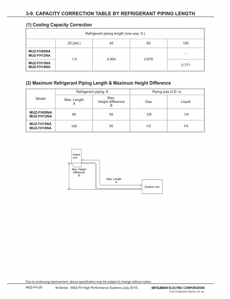
3-9. CAPACITY CORRECTION TABLE BY REFRIGERANT PIPING LENGTH
Max. Length A
Max. Heightdifference
B
Indoorunit
Outdoor unit
Model
Refrigerant piping: ft. Piping size O.D: in.
Max. Length A
Max. Height difference
B Gas Liquid
MUZ-FH09NAMUZ-FH12NA 65 40 3/8 1/4
MUZ-FH15NA MUZ-FH18NA 100 50 1/2 1/4
Refrigerant piping length (one way: ft.)
25 (std.) 40 65 100
MUZ-FH09NAMUZ-FH12NA
1.0 0.954 0.878
-
MUZ-FH15NAMUZ-FH18NA 0.771
(2) Maximum Refrigerant Piping Length & Maximum Height Difference
(1) Cooling Capacity Correction
Page 29
M-Series - MSZ-FH High Performance Systems (July 2015) MSZ-FH-29© 2014 Mitsubishi Electric US, Inc.
Due to continuing improvement, above specification may be subject to change without notice.
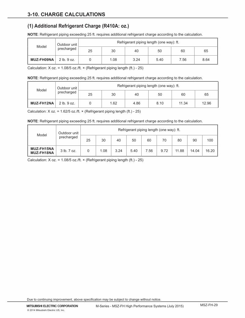
3-10. CHARGE CALCULATIONS
(1) Additional Refrigerant Charge (R410A: oz.) NOTE: Refrigerant piping exceeding 25 ft. requires additional refrigerant charge according to the calculation.
Model Outdoor unit precharged
Refrigerant piping length (one way): ft.
25 30 40 50 60 65
MUZ-FH09NA 2 lb. 9 oz. 0 1.08 3.24 5.40 7.56 8.64
Calculation: X oz. = 1.08/5 oz./ft. × (Refrigerant piping length (ft.) - 25)
NOTE: Refrigerant piping exceeding 25 ft. requires additional refrigerant charge according to the calculation.
Model Outdoor unit precharged
Refrigerant piping length (one way): ft.
25 30 40 50 60 65
MUZ-FH12NA 2 lb. 9 oz. 0 1.62 4.86 8.10 11.34 12.96
Calculation: X oz. = 1.62/5 oz./ft. × (Refrigerant piping length (ft.) - 25)
NOTE: Refrigerant piping exceeding 25 ft. requires additional refrigerant charge according to the calculation.
Model Outdoor unit precharged
Refrigerant piping length (one way): ft.
25 30 40 50 60 70 80 90 100
MUZ-FH15NAMUZ-FH18NA 3 lb. 7 oz. 0 1.08 3.24 5.40 7.56 9.72 11.88 14.04 16.20
Calculation: X oz. = 1.08/5 oz./ft. × (Refrigerant piping length (ft.) - 25)
Page 30
MSZ-FH-30 M-Series - MSZ-FH High Performance Systems (July 2015)
Due to continuing improvement, above specification may be subject to change without notice.
© 2014 Mitsubishi Electric US, Inc.
3-11. AIR FLOW DATA
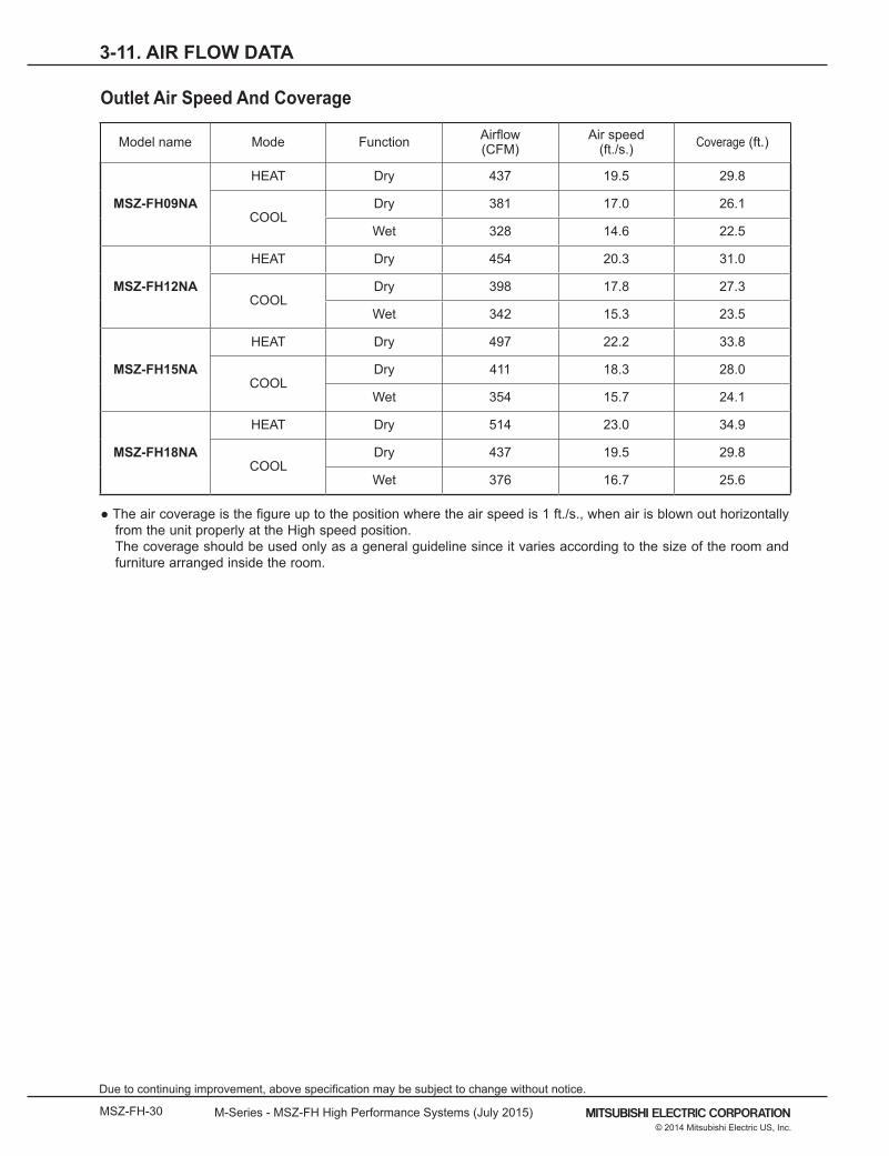
● The air coverage is the figure up to the position where the air speed is 1 ft./s., when air is blown out horizontally from the unit properly at the High speed position.
The coverage should be used only as a general guideline since it varies according to the size of the room and furniture arranged inside the room.
Model name Mode Function Airflow(CFM)
Air speed(ft./s.) Coverage (ft.)
MSZ-FH09NA
HEAT Dry 437 19.5 29.8
COOLDry 381 17.0 26.1
Wet 328 14.6 22.5
MSZ-FH12NA
HEAT Dry 454 20.3 31.0
COOLDry 398 17.8 27.3
Wet 342 15.3 23.5
MSZ-FH15NA
HEAT Dry 497 22.2 33.8
COOLDry 411 18.3 28.0
Wet 354 15.7 24.1
MSZ-FH18NA
HEAT Dry 514 23.0 34.9
COOLDry 437 19.5 29.8
Wet 376 16.7 25.6
Outlet Air Speed And Coverage
Page 31
M-Series - MSZ-FH High Performance Systems (July 2015) MSZ-FH-31© 2014 Mitsubishi Electric US, Inc.
Due to continuing improvement, above specification may be subject to change without notice.
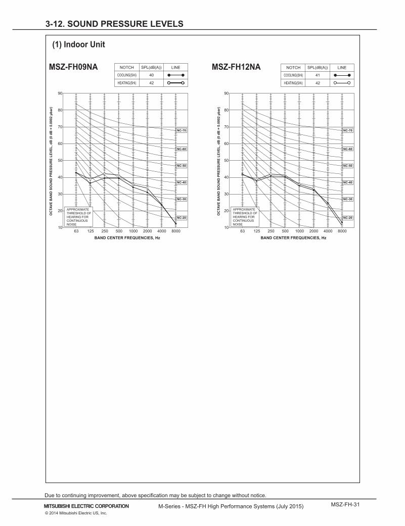
3-12. SOUND PRESSURE LEVELS
(1) Indoor Unit
90
80
70
60
50
40
30
20
1063 125 250 500 1000 2000 4000 8000
NC-60
NC-50
NC-40
NC-30
NC-20
NC-70
BAND CENTER FREQUENCIES, Hz
APPROXIMATETHRESHOLD OF HEARING FORCONTINUOUSNOISE
COOLING(SHi)
SPL(dB(A)) LINE
HEATING(SHi)
40
42
OC
TAVE
BA
ND
SO
UN
D P
RES
SUR
E LE
VEL,
dB
(0 d
B =
0.0
002
µbar
)
MSZ-FH09NA
90
80
70
60
50
40
30
20
1063 125 250 500 1000 2000 4000 8000
NC-60
NC-50
NC-40
NC-30
NC-20
NC-70
BAND CENTER FREQUENCIES, Hz
SPL(dB(A)) LINE
41
42
OC
TAVE
BA
ND
SO
UN
D P
RES
SUR
E LE
VEL,
dB
(0 d
B =
0.0
002
µbar
)
MSZ-FH12NA
APPROXIMATETHRESHOLD OF HEARING FORCONTINUOUSNOISE
NOTCH
COOLING(SHi)
HEATING(SHi)
NOTCHMSZ-FH09NA MSZ-FH12NA
Page 32
MSZ-FH-32 M-Series - MSZ-FH High Performance Systems (July 2015)
Due to continuing improvement, above specification may be subject to change without notice.
© 2014 Mitsubishi Electric US, Inc.
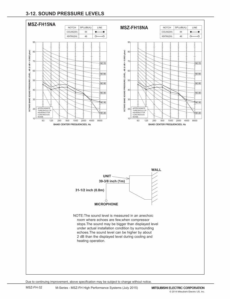
3-12. SOUND PRESSURE LEVELS
NOTE: The sound level is measured in an anechoic room where echoes are few, when compressor stops. The soundmay be bigger than displayed level under actual installation condition by surrounding echoes. The sound levelcan be higher by about 2 dB than the displayed level during cooling and heating operation.
WALL
UNIT
31-1/2 inch (0.8m)
39-3/8 inch (1m)
MICROPHONE
90
80
70
60
50
40
30
20
1063 125 250 500 1000 2000 4000 8000
NC-60
NC-50
NC-40
NC-30
NC-20
NC-70
BAND CENTER FREQUENCIES, Hz
APPROXIMATETHRESHOLD OF HEARING FORCONTINUOUSNOISE
SPL(dB(A)) LINE
53O
CTA
VE B
AN
D S
OU
ND
PR
ESSU
RE
LEVE
L, d
B (0
dB
= 0
.000
2 µb
ar)
MSZ-FE18NA
90
80
70
60
50
40
30
20
1063 125 250 500 1000 2000 4000 8000
NC-60
NC-50
NC-40
NC-30
NC-20
NC-70
BAND CENTER FREQUENCIES, Hz
SPL(dB(A)) LINE
49
OC
TAVE
BA
ND
SO
UN
D P
RES
SUR
E LE
VEL,
dB
(0 d
B =
0.0
002
µbar
)
MSZ-D30NAMSZ-D36NAMSY-D30NAMSY-D36NA
APPROXIMATETHRESHOLD OF HEARING FORCONTINUOUSNOISE
53
COOLING(Rated)
HEATING(Rated)
NOTCH
COOLING(Hi)
HEATING(Hi)
NOTCH
NOTE:The sound level is measured in an anechoic room where echoes are few,when compressor stops.The sound may be bigger than displayed level under actual installation condition by surrounding echoes.The sound level can be higher by about 2 dB than the displayed level during cooling and heating operation.
90
80
70
60
50
40
30
20
1063 125 250 500 1000 2000 4000 8000
NC-60
NC-50
NC-40
NC-30
NC-20
NC-70
BAND CENTER FREQUENCIES, Hz
SPL(dB(A)) LINE
44
46
OC
TAVE
BA
ND
SO
UN
D P
RES
SUR
E LE
VEL,
dB
(0 d
B =
0.0
002
µbar
)MSZ-FH15NA
APPROXIMATETHRESHOLD OF HEARING FORCONTINUOUSNOISE
COOLING(SHi)
HEATING(SHi)
NOTCH
90
80
70
60
50
40
30
20
1063 125 250 500 1000 2000 4000 8000
NC-60
NC-50
NC-40
NC-30
NC-20
NC-70
BAND CENTER FREQUENCIES, Hz
SPL(dB(A)) LINE
44
46
OC
TAVE
BA
ND
SO
UN
D P
RES
SUR
E LE
VEL,
dB
(0 d
B =
0.0
002
µbar
)
MSZ-FH18NA
APPROXIMATETHRESHOLD OF HEARING FORCONTINUOUSNOISE
COOLING(SHi)
HEATING(SHi)
NOTCHMSZ-FH18NAMSZ-FH15NA
Page 33
M-Series - MSZ-FH High Performance Systems (July 2015) MSZ-FH-33© 2014 Mitsubishi Electric US, Inc.
Due to continuing improvement, above specification may be subject to change without notice.
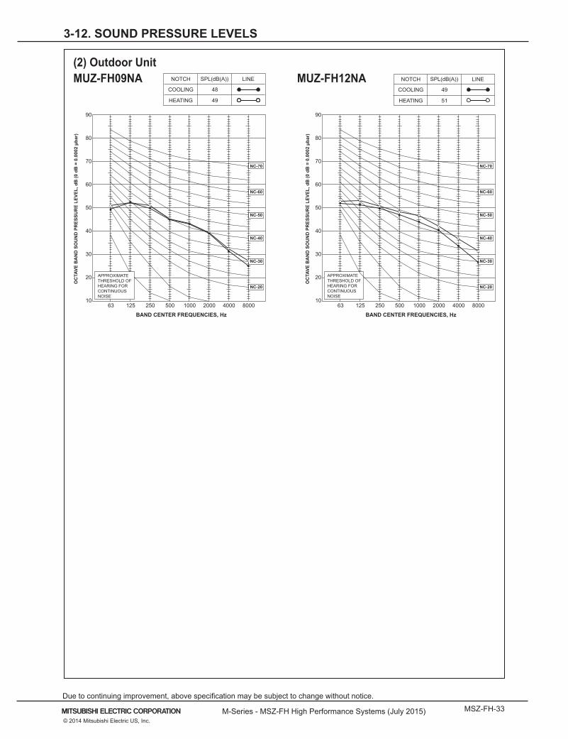
3-12. SOUND PRESSURE LEVELS
(2) Outdoor Unit
90
80
70
60
50
40
30
20
1063 125 250 500 1000 2000 4000 8000
NC-60
NC-50
NC-40
NC-30
NC-20
NC-70
BAND CENTER FREQUENCIES, Hz
APPROXIMATETHRESHOLD OF HEARING FORCONTINUOUSNOISE
COOLING
SPL(dB(A)) LINE
HEATING
48
49
OC
TAVE
BA
ND
SO
UN
D P
RES
SUR
E LE
VEL,
dB
(0 d
B =
0.0
002
µbar
)MUZ-FH09NAMUZ-FH09NAH
90
80
70
60
50
40
30
20
1063 125 250 500 1000 2000 4000 8000
NC-60
NC-50
NC-40
NC-30
NC-20
NC-70
BAND CENTER FREQUENCIES, Hz
SPL(dB(A)) LINE
49
51
OC
TAVE
BA
ND
SO
UN
D P
RES
SUR
E LE
VEL,
dB
(0 d
B =
0.0
002
µbar
)
MUZ-FH12NAMUZ-FH12NAH
APPROXIMATETHRESHOLD OF HEARING FORCONTINUOUSNOISE
NOTCH
COOLING
HEATING
NOTCHMUZ-FH09NA MUZ-FH12NA
Page 34
MSZ-FH-34 M-Series - MSZ-FH High Performance Systems (July 2015)
Due to continuing improvement, above specification may be subject to change without notice.
© 2014 Mitsubishi Electric US, Inc.
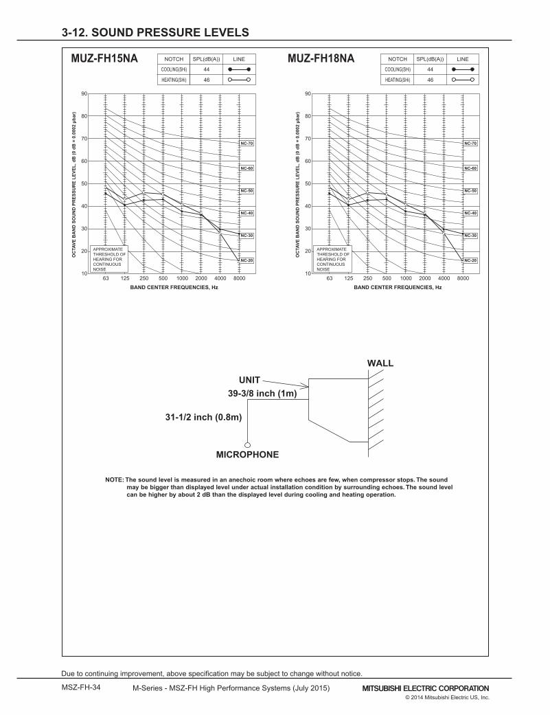
90
80
70
60
50
40
30
20
1063 125 250 500 1000 2000 4000 8000
NC-60
NC-50
NC-40
NC-30
NC-20
NC-70
BAND CENTER FREQUENCIES, Hz
SPL(dB(A)) LINE
44
46O
CTA
VE B
AN
D S
OU
ND
PR
ESSU
RE
LEVE
L, d
B (0
dB
= 0
.000
2 µb
ar)
MSZ-FH15NA
APPROXIMATETHRESHOLD OF HEARING FORCONTINUOUSNOISE
COOLING(SHi)
HEATING(SHi)
NOTCH
90
80
70
60
50
40
30
20
1063 125 250 500 1000 2000 4000 8000
NC-60
NC-50
NC-40
NC-30
NC-20
NC-70
BAND CENTER FREQUENCIES, Hz
SPL(dB(A)) LINE
44
46
OC
TAVE
BA
ND
SO
UN
D P
RES
SUR
E LE
VEL,
dB
(0 d
B =
0.0
002
µbar
)
MSZ-FH18NA
APPROXIMATETHRESHOLD OF HEARING FORCONTINUOUSNOISE
COOLING(SHi)
HEATING(SHi)
NOTCHMUZ-FH15NA MUZ-FH18NA
NOTE: The sound level is measured in an anechoic room where echoes are few, when compressor stops. The soundmay be bigger than displayed level under actual installation condition by surrounding echoes. The sound levelcan be higher by about 2 dB than the displayed level during cooling and heating operation.
WALL
UNIT
31-1/2 inch (0.8m)
39-3/8 inch (1m)
MICROPHONE
90
80
70
60
50
40
30
20
1063 125 250 500 1000 2000 4000 8000
NC-60
NC-50
NC-40
NC-30
NC-20
NC-70
BAND CENTER FREQUENCIES, Hz
APPROXIMATETHRESHOLD OF HEARING FORCONTINUOUSNOISE
SPL(dB(A)) LINE
53
OC
TAVE
BA
ND
SO
UN
D P
RES
SUR
E LE
VEL,
dB
(0 d
B =
0.0
002
µbar
)
MSZ-FE18NA
90
80
70
60
50
40
30
20
1063 125 250 500 1000 2000 4000 8000
NC-60
NC-50
NC-40
NC-30
NC-20
NC-70
BAND CENTER FREQUENCIES, Hz
SPL(dB(A)) LINE
49
OC
TAVE
BA
ND
SO
UN
D P
RES
SUR
E LE
VEL,
dB
(0 d
B =
0.0
002
µbar
)
MSZ-D30NAMSZ-D36NAMSY-D30NAMSY-D36NA
APPROXIMATETHRESHOLD OF HEARING FORCONTINUOUSNOISE
53
COOLING(Rated)
HEATING(Rated)
NOTCH
COOLING(Hi)
HEATING(Hi)
NOTCH
3-12. SOUND PRESSURE LEVELS
Page 35
M-Series - MSZ-FH High Performance Systems (July 2015) MSZ-FH-35© 2014 Mitsubishi Electric US, Inc.
Due to continuing improvement, above specification may be subject to change without notice.
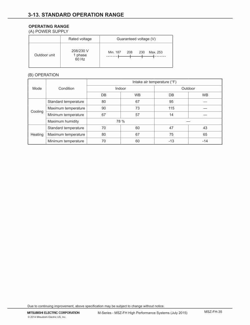
3-13. STANDARD OPERATION RANGE
(B) OPERATION
Mode Condition
Intake air temperature (°F)
Indoor Outdoor
DB WB DB WB
Cooling
Standard temperature 80 67 95 —
Maximum temperature 90 73 115 —
Minimum temperature 67 57 14 —
Maximum humidity 78 % —
Heating
Standard temperature 70 60 47 43
Maximum temperature 80 67 75 65
Minimum temperature 70 60 -13 -14
OPERATING RANGE(A) POWER SUPPLY
Rated voltage Guaranteed voltage (V)
Outdoor unit 208/230 V 1 phase 60 Hz
Min. 187 208 230 Max. 253
Page 36
MSZ-FH-36 M-Series - MSZ-FH High Performance Systems (July 2015)
Due to continuing improvement, above specification may be subject to change without notice.
© 2014 Mitsubishi Electric US, Inc.
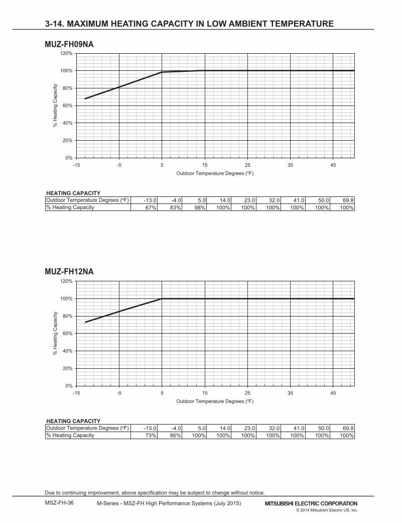
3-14. MAXIMUM HEATING CAPACITY IN LOW AMBIENT TEMPERATURE
MUZ-FH09NA
MUZ-FH12NA
HEATING CAPACITY-13.0 -4.0 5.0 14.0 23.0 32.0 41.0 50.0 69.8
0%
20%
40%
60%
80%
100%
120%
-15 -5 5 15 25 35 45
Outdoor Temperature Degrees (oF)
% H
eatin
g C
apac
ity
Outdoor Temperature Degrees (oF)% Heating Capacity 67% 83% 98% 100% 100% 100% 100% 100% 100%
HEATING CAPACITY-13.0 -4.0 5.0 14.0 23.0 32.0 41.0 50.0 69.8
0%
20%
40%
60%
80%
100%
120%
-15 -5 5 15 25 35 45
Outdoor Temperature Degrees (oF)
% H
eatin
g C
apac
ity
Outdoor Temperature Degrees (oF)% Heating Capacity 73% 86% 100% 100% 100% 100% 100% 100% 100%
Page 37
M-Series - MSZ-FH High Performance Systems (July 2015) MSZ-FH-37© 2014 Mitsubishi Electric US, Inc.
Due to continuing improvement, above specification may be subject to change without notice.
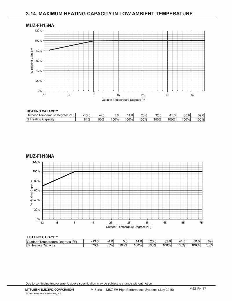
3-14. MAXIMUM HEATING CAPACITY IN LOW AMBIENT TEMPERATURE
MUZ-FH15NA
HEATING CAPACITY-13.0 -4.0 5.0 14.0 23.0 32.0 41.0 50.0 69.8
0%
20%
40%
60%
80%
100%
120%
-15 -5 5 15 25 35 45
Outdoor Temperature Degrees (oF)
% H
eatin
g C
apac
ity
Outdoor Temperature Degrees (oF)% Heating Capacity 81% 90% 100% 100% 100% 100% 100% 100% 100%
MUZ-FH18NA
HEATING CAPACITYOutdoor Temperature Degrees (oF) -13.0 -4.0 5.0 14.0 23.0 32.0 41.0 50.0 69.8 75.0
%001%001%001%001%001%001%001%001%58%07yticapaC gnitaeH %
0%
20%
40%
60%
80%
100%
120%
% H
eatin
g C
apac
ity
-13 -5 5 15 25 35 45 55 65 75Outdoor Temperature Degrees (ºF)
Page 38
MSZ-FH-38 M-Series - MSZ-FH High Performance Systems (July 2015)
Due to continuing improvement, above specification may be subject to change without notice.
© 2014 Mitsubishi Electric US, Inc.
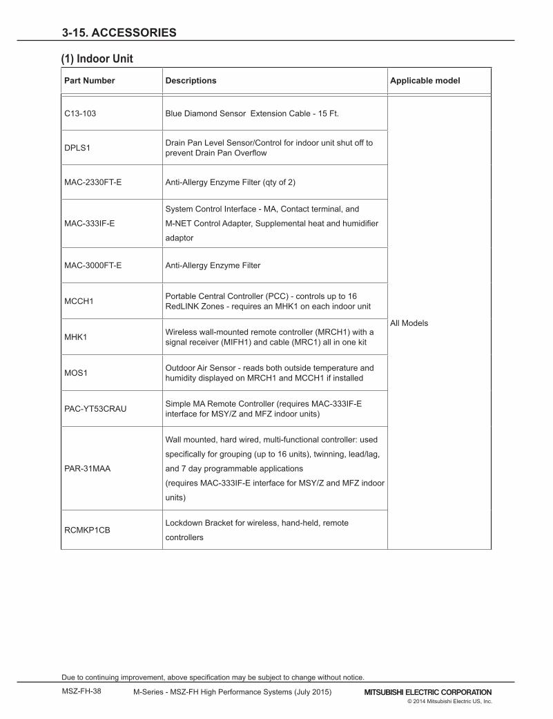
(1) Indoor Unit
Part Number Descriptions Applicable model
C13-103 Blue Diamond Sensor Extension Cable - 15 Ft.
All Models
DPLS1 Drain Pan Level Sensor/Control for indoor unit shut off to prevent Drain Pan Overflow
MAC-2330FT-E Anti-Allergy Enzyme Filter (qty of 2)
MAC-333IF-E
System Control Interface - MA, Contact terminal, and
M-NET Control Adapter, Supplemental heat and humidifier
adaptor
MAC-3000FT-E Anti-Allergy Enzyme Filter
MCCH1 Portable Central Controller (PCC) - controls up to 16 RedLINK Zones - requires an MHK1 on each indoor unit
MHK1 Wireless wall-mounted remote controller (MRCH1) with a signal receiver (MIFH1) and cable (MRC1) all in one kit
MOS1 Outdoor Air Sensor - reads both outside temperature and humidity displayed on MRCH1 and MCCH1 if installed
PAC-YT53CRAU Simple MA Remote Controller (requires MAC-333IF-E interface for MSY/Z and MFZ indoor units)
PAR-31MAA
Wall mounted, hard wired, multi-functional controller: used
specifically for grouping (up to 16 units), twinning, lead/lag,
and 7 day programmable applications
(requires MAC-333IF-E interface for MSY/Z and MFZ indoor
units)
RCMKP1CBLockdown Bracket for wireless, hand-held, remote
controllers
3-15. ACCESSORIES
Page 39
M-Series - MSZ-FH High Performance Systems (July 2015) MSZ-FH-39© 2014 Mitsubishi Electric US, Inc.
Due to continuing improvement, above specification may be subject to change without notice.
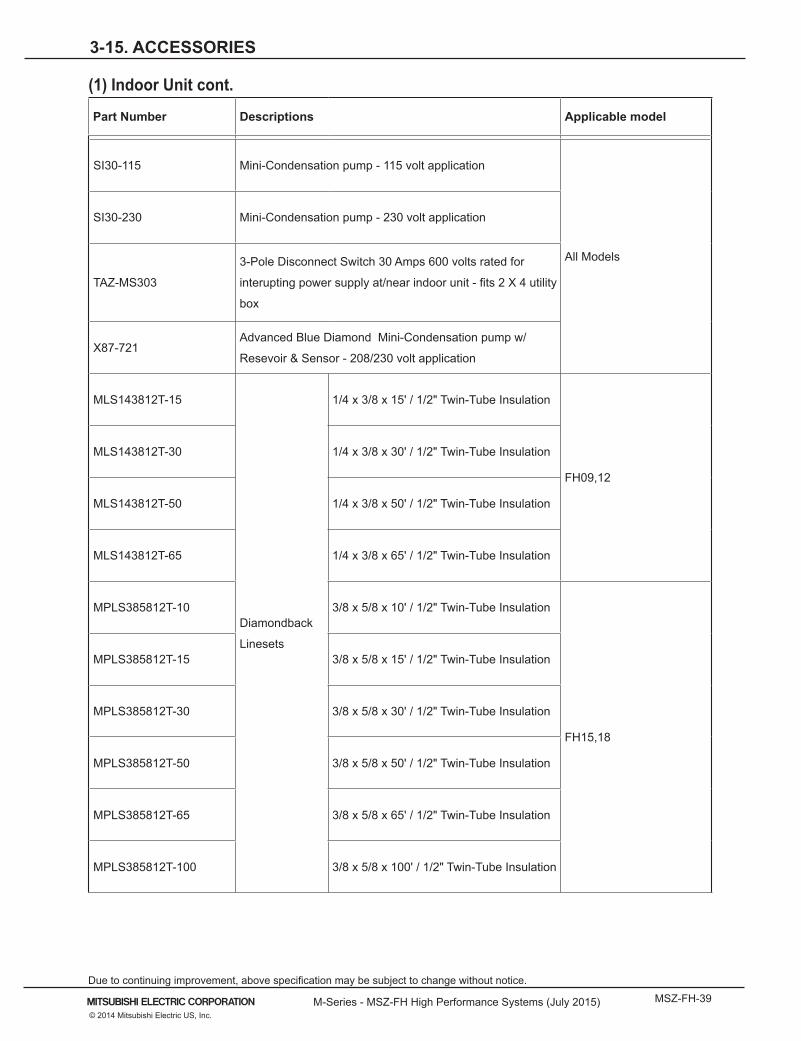
(1) Indoor Unit cont.
Part Number Descriptions Applicable model
SI30-115 Mini-Condensation pump - 115 volt application
All Models
SI30-230 Mini-Condensation pump - 230 volt application
TAZ-MS303
3-Pole Disconnect Switch 30 Amps 600 volts rated for
interupting power supply at/near indoor unit - fits 2 X 4 utility
box
X87-721Advanced Blue Diamond Mini-Condensation pump w/
Resevoir & Sensor - 208/230 volt application
MLS143812T-15
Diamondback
Linesets
1/4 x 3/8 x 15' / 1/2" Twin-Tube Insulation
FH09,12
MLS143812T-30 1/4 x 3/8 x 30' / 1/2" Twin-Tube Insulation
MLS143812T-50 1/4 x 3/8 x 50' / 1/2" Twin-Tube Insulation
MLS143812T-65 1/4 x 3/8 x 65' / 1/2" Twin-Tube Insulation
MPLS385812T-10 3/8 x 5/8 x 10' / 1/2" Twin-Tube Insulation
FH15,18
MPLS385812T-15 3/8 x 5/8 x 15' / 1/2" Twin-Tube Insulation
MPLS385812T-30 3/8 x 5/8 x 30' / 1/2" Twin-Tube Insulation
MPLS385812T-50 3/8 x 5/8 x 50' / 1/2" Twin-Tube Insulation
MPLS385812T-65 3/8 x 5/8 x 65' / 1/2" Twin-Tube Insulation
MPLS385812T-100 3/8 x 5/8 x 100' / 1/2" Twin-Tube Insulation
3-15. ACCESSORIES
Page 40
MSZ-FH-40 M-Series - MSZ-FH High Performance Systems (July 2015)
Due to continuing improvement, above specification may be subject to change without notice.
© 2014 Mitsubishi Electric US, Inc.
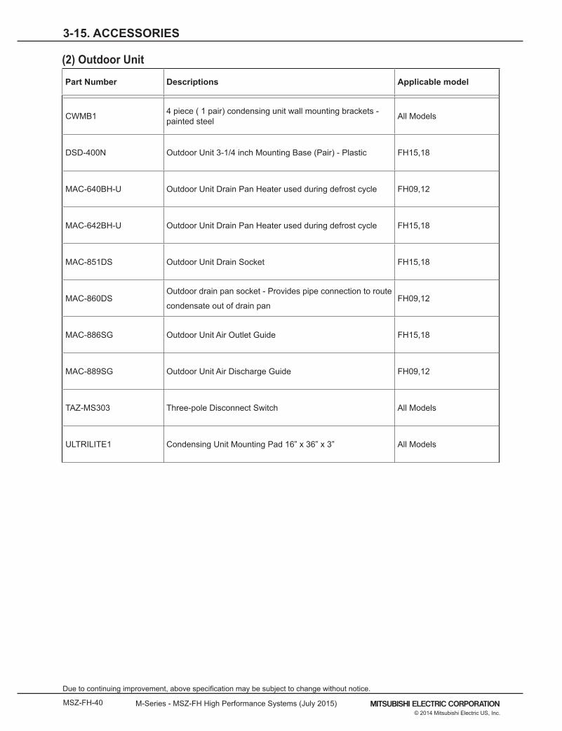
3-15. ACCESSORIES
(2) Outdoor Unit
Part Number Descriptions Applicable model
CWMB1 4 piece ( 1 pair) condensing unit wall mounting brackets - painted steel All Models
DSD-400N Outdoor Unit 3-1/4 inch Mounting Base (Pair) - Plastic FH15,18
MAC-640BH-U Outdoor Unit Drain Pan Heater used during defrost cycle FH09,12
MAC-642BH-U Outdoor Unit Drain Pan Heater used during defrost cycle FH15,18
MAC-851DS Outdoor Unit Drain Socket FH15,18
MAC-860DSOutdoor drain pan socket - Provides pipe connection to route
condensate out of drain panFH09,12
MAC-886SG Outdoor Unit Air Outlet Guide FH15,18
MAC-889SG Outdoor Unit Air Discharge Guide FH09,12
TAZ-MS303 Three-pole Disconnect Switch All Models
ULTRILITE1 Condensing Unit Mounting Pad 16” x 36” x 3” All Models