STEAM BATH® RESIDENTIAL STEAM GENERATORS R R R E E E S S S I I I D D D E E E N N N T T T I I I A A A L L L S S S T T T E E E A A A M M M G G G E E E N N N E E E R R R A A A T T T O O O R R R S S S I I I N N N S S S T T T A A A L L L L L L A A A T T T I I I O O O N N N , , , O O O P P P E E E R R R A A A T T T I I I O O O N N N A A A N N N D D D M M M A A A I I I N N N T T T E E E N N N A A A N N N C C C E E E M M M A A A N N N U U U A A A L L L STEAM STEAM STEAM STEAM BATH® BATH® BATH® BATH®
Transcript
STEAM BATH®
RESIDENTIAL STEAM GENERATORS
RR REE ESS SII I DD DEE ENN NTT TII I AA ALL L SS STT TEE EAA AMM M GG GEE ENN NEE ERR RAA ATT TOO ORR RSS S
II I NN NSS STT TAA ALL LLL LAA ATT TII I OO ONN N,, , OO OPP PEE ERR RAA ATT TII I OO ONN N AA ANN NDD D MM MAA AII I NN NTT TEE ENN NAA ANN NCC CEE E MM MAA ANN NUU UAA ALL L
Steam Sauna Inc manufactures steam generators for any steam bath need. They are the result of many years of continued research. From the smallest residential unit to the largest commercial unit, our products are manufactured to the same rigid quality standard. We also custom build for those specialized applications e.g. yachts, Recreational Vehicles (RV’s), specialized home or commercial use, executive fitness rooms etc. Your Steam Bath® residential steam generator has been tested and approved by CSA and listed with UL, also manufactured as per ISO 9001:2000 Quality Management System, so you are assured of the highest quality and safety standard.
1. Read all instructions in this guide prior to installing your steam generator. 2. Always ground the unit properly. 3. Make sure there are no restrictions in the steam line(s). 4. Always turn off the electrical supply and close the water line before doing any
work on the unit. 5. Use caution when near the steam head(s). They are very hot and may cause
personal injury. 6. If you become overheated while in the steam bath, you should turn on the
cold shower, open the door and step out of the bath. 7. If you are pregnant, have heart problems, high blood pressure or physical
symptoms other than normal, consult with your doctor to determine if you should currently use a steam room.
8. Never use a steam bath after consuming alcohol or mind altering drugs. 9. Do not allow children to use a steam bath without adult supervision. 10. This unit is designed for steam baths only. If you wish to use it for other
purposes, contact the manufacturer to find out if it is suited for your application.
If you are using an existing tiled shower or bathtub enclosure, make sure that it is enclosed to the ceiling.
Locating the Unit Plan the location of your steam unit carefully. Place it for convenient installation and easy access. A good location, when possible, is a furnace or storage room. Do not bury the unit in walls or other inconvenient locations as it may require periodic maintenance. It may be placed up to 50 ft.(15m) from the steam room. A gravity drain will be necessary for all units requiring drainage. Never locate the unit in an area that may be exposed to frost.
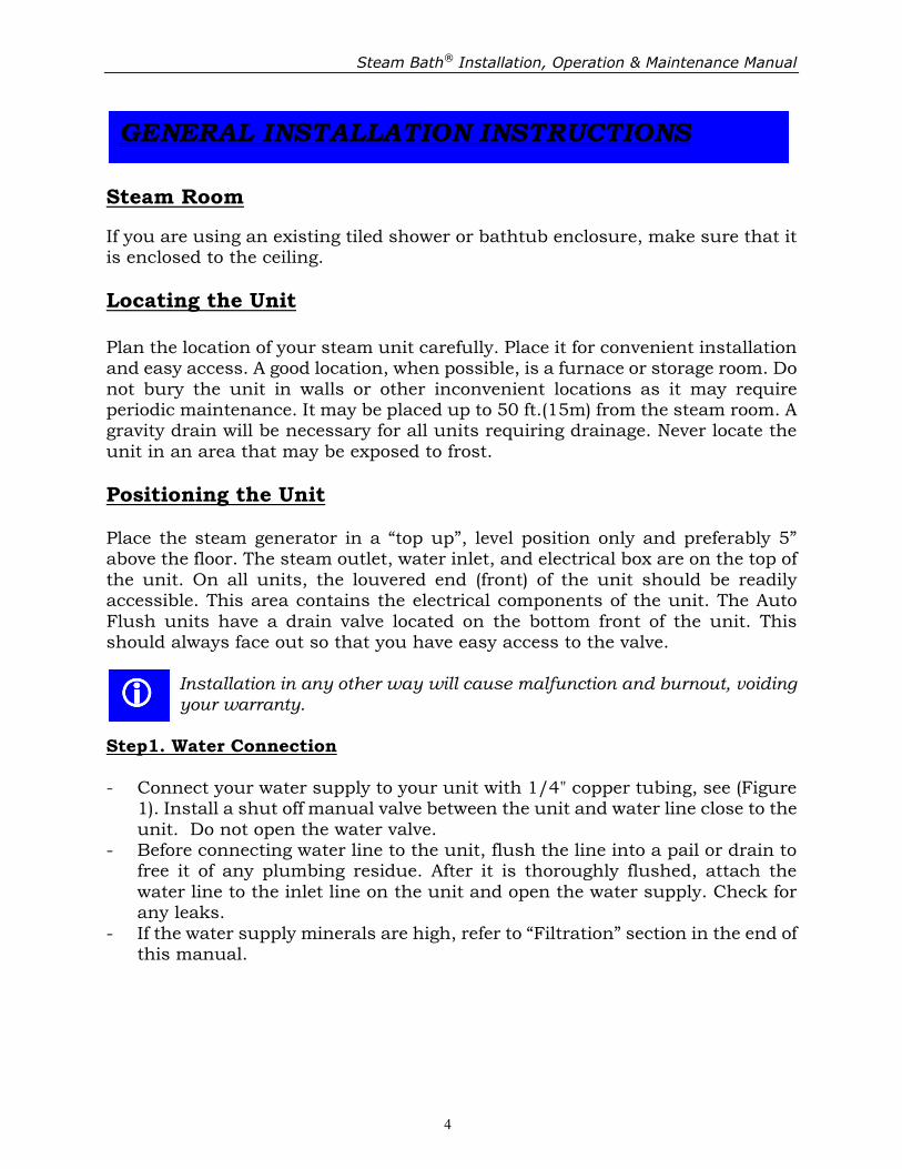
Positioning the Unit Place the steam generator in a “top up”, level position only and preferably 5” above the floor. The steam outlet, water inlet, and electrical box are on the top of the unit. On all units, the louvered end (front) of the unit should be readily accessible. This area contains the electrical components of the unit. The Auto Flush units have a drain valve located on the bottom front of the unit. This should always face out so that you have easy access to the valve.
Installation in any other way will cause malfunction and burnout, voiding your warranty.
Step1. Water Connection - Connect your water supply to your unit with 1/4" copper tubing, see (Figure
1). Install a shut off manual valve between the unit and water line close to the unit. Do not open the water valve.
- Before connecting water line to the unit, flush the line into a pail or drain to free it of any plumbing residue. After it is thoroughly flushed, attach the water line to the inlet line on the unit and open the water supply. Check for any leaks.
- If the water supply minerals are high, refer to “Filtration” section in the end of this manual.
Step2. Steam Connection - A compression fitting is supplied at the steam outlet(s) on the top of the
steam generator and a ½" copper pipe fits this fitting, see (Figure 1). Plumb from this point to the location of the steam head or vice versa. Do not have any low points in this line that will allow condensation to sit in the pipe. Insulate the steam pipe to prevent temperature loss in output steam, caused by heat exchange between pipe and surrounding air.
- Drill a 3/4" hole into your steam room, 6"-12" above the floor or approximately 6" above the edge of your bathtub. Locate the steam head in an area where you will easily avoid physical contact. Connect the steam head to the pipe that you have brought through the hole into the steam room. Direct the steam outlet slot in the steam head down toward the floor.
����Do not install any valves or limiter between the unit and the steam head that
will cause the pressure to build up in the unit. Step3. Drain Connection
This is a gravity drain on all units with Auto Flush option. A compression fitting is supplied with the unit and is to be installed on a ½" copper pipe that slopes slightly downward and away from the unit. It may run to an open floor drain or it can be plumbed into an existing drain line.
����The draining water is hot, avoid touching the drain pipe that it may cause
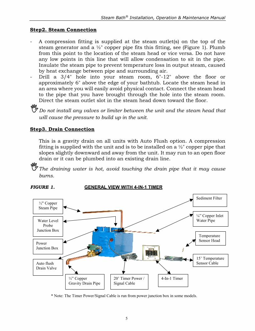
burns. FIGURE 1. GENERAL VIEW WITH 4-IN-1 TIMER
½" Copper
Steam Pipe
Power
Junction Box
Auto flush
Drain Valve
½” Copper
Gravity Drain Pipe 20’ Timer Power /
Signal Cable
4-In-1 Timer
Sediment Filter
¼” Copper Inlet
Water Pipe
Temperature
Sensor Head
15’ Temperature
Sensor Cable
* Note: The Timer Power/Signal Cable is run from power junction box in some models.
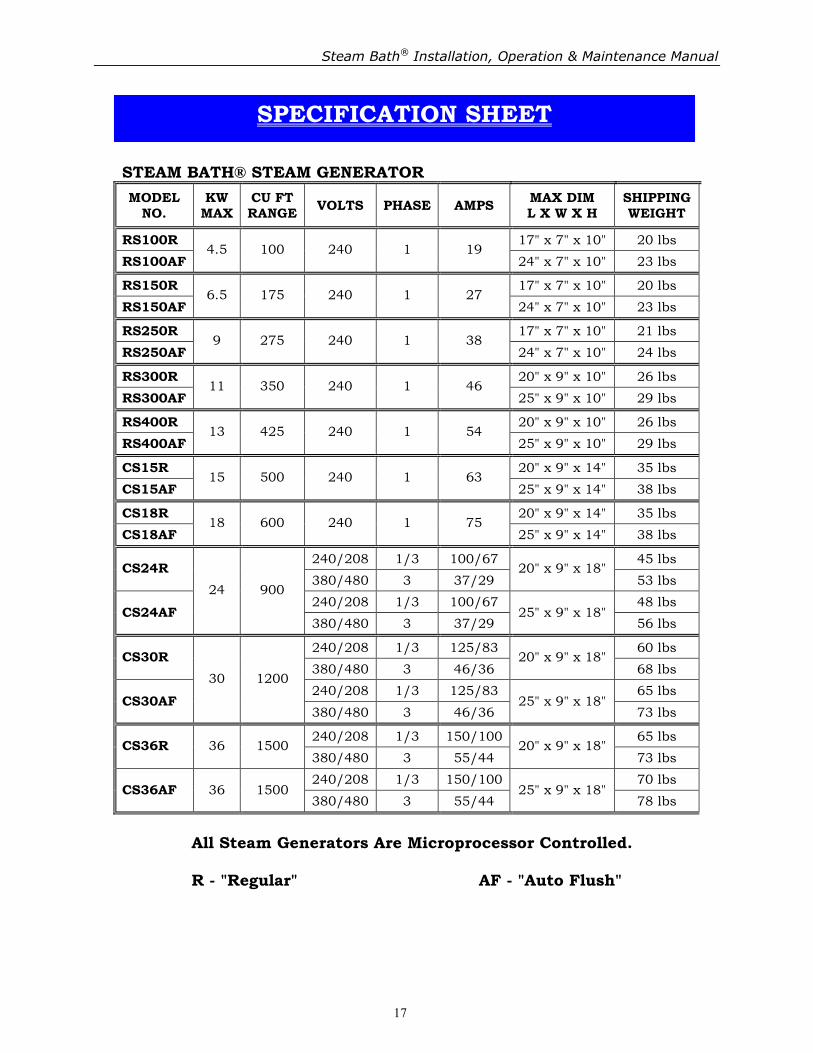
Have a qualified electrician connect the unit. The power cable size and breaker size is to be determined by an electrician. Use the specification sheet at the end of this manual to find the voltage and wattage rating of your unit. All applicable electrical codes must be strictly adhered to. Check your supply voltage to ensure it is compatible with the voltage listed on your unit’s label.
A. Steam Generators with regular 30 Minutes Timer or ON/OFF Switch or Thermostat
A-1. Electrical Power Connection - Install a Circuit Breaker in your Power Distribution Panel. Label that breaker
as “Steam Gen” Select Circuit Breaker size according to electrical codes. Run the power cable from Circuit breaker to the unit and connect it to L1 and L2 (and L3 in 3 phase models) in the electrical box on top of the unit (240 Volts or 208 Volts in 3 phase models) (Figure 2). Fasten the ground wire to the ground terminal in electrical box.
����Do not connect Neutral to the Ground Terminal.
����Do not connect the 30 min. timer to L1 & L2 power source, as this will cause
some models of our steam generators to malfunction. A-2. The Timer / Thermostat Connection - In Power Junction Box, you will find 2 orange wires: Connect them to 30
Minuets timer or your timer/thermostat leads (Figure 2). - You can only connect the orange wires to a power free contact, because these
wires are powered from the circuit board (DC Volts) within the unit, do not connect any other power source to the timer/thermostat.
If it is necessary to power your timer/thermostat, a separate relay must be used to isolate the circuits. Failure to follow this instruction will void the warranty on the unit.
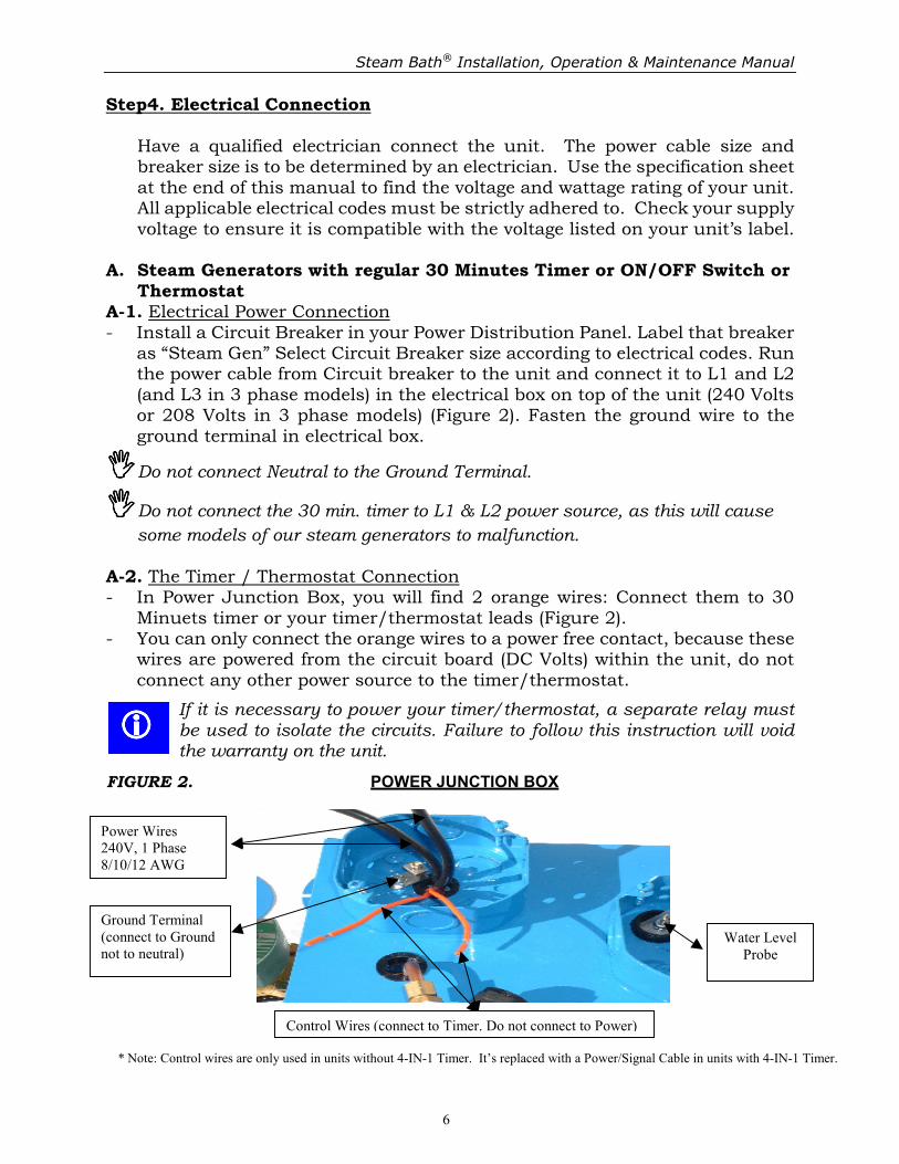
FIGURE 2. POWER JUNCTION BOX
Power Wires
240V, 1 Phase
8/10/12 AWG
Ground Terminal
(connect to Ground
not to neutral)
Control Wires (connect to Timer. Do not connect to Power)
* Note: Control wires are only used in units without 4-IN-1 Timer. It’s replaced with a Power/Signal Cable in units with 4-IN-1 Timer.
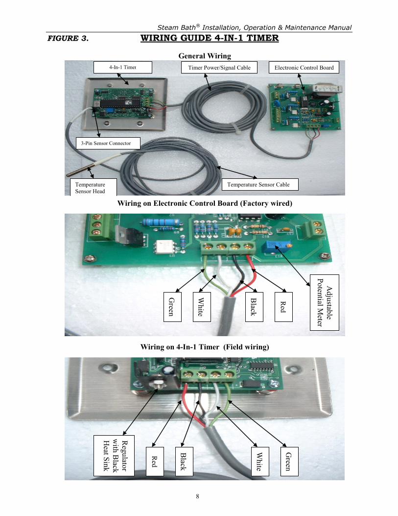
B. Steam Generators with “Four-In-One” Digital Timer B-1. Same as “Step 4. A-1.” above. B-2. Install the Box for “Four-In-One” Digital Timer outside the steam room and
in the vicinity of the door, and then connect the following cables: - Run “Timer’s power/signal cable” from the steam generator to
“Four-In-One” Digital Timer and connect the wires according to (Figure 3) to the 4 slot terminal on the board.
- Install the temperature sensor in the steam room. It has to be installed in the opposite corner to where the steam head is installed and 5” above the door. The probe has to be exposed 1.5” outside the wall (inside room). Run the sensor cable from steam room to the “Four-In-One” Digital Timer and connect it to the 3pin connector on the board. It can only be inserted in one direction.
- Put the “Four-In-One” Digital Timer in its box and secure it with 4 screws. Step5. Testing
Now that your Steam Bath® steam generator is connected, you are ready to test it.
A. Steam Generators with regular 30 Minutes Timer or Thermostat A-1. Open the water supply and recheck for leaks. A-2. Turn on the circuit breaker at the panel and test to be sure the unit is
receiving power. A-3. Set the timer to the desired time and/or set the thermostat to the desired
temperature, within minutes you will have steam. - Make sure the steam line does not leak.
B. Steam Generators with “Four-In-One” Digital Timer B-1. Same as “Step 5. A-1.” above. B-2. Same as “Step 5. A-2.” above. B-3. Touch the “ON” button on “Four-In-One” Digital Timer to turn on the unit
(see page 8 for more details). Safety Note: Regarding the safety of users, an “Automatic Safety Shut Off” feature shuts down the unit after one hour continuous usage. If you need to restart the unit, first reset the timer, then set it for desired time again.
The timer is capable of performing 8 different functions: ���� Clock: Displays the current time. ���� Clock Set: Sets the clock. ���� Auto Start (option): Sets the Auto Start time, which turns on the unit at the
desired time automatically. ���� Auto Stop (option): Sets the Auto Stop time, which turns off the unit at a
time interval after Auto Start Time. ���� Time: Displays the time period that unit will be ON, which by
default is set to 30 minutes. ���� Timer Set: Sets the Timer to run the unit for a longer or shorter
period than 30 minutes but at the end of the period it sets back to the default (30 minutes).
���� Temp.: Displays the current temperature in the steam room. ���� Temp. Set: Sets the target temperature in the steam room, which
is 47°C/117°F by default. Buttons There are four push & release type buttons on the timer which are used to set up different functions on the timer: ���� Mode: The “Mode” button moves the lights to 8 different functions on the
timer to select the desired function. ���� Set: The “Set” button saves the value that you have entered to each
function. ���� Next: The “Next” button moves the flashing digit on display to the right,
also used to turn on the unit. ���� Inc.: The “Inc.” button increments the value of the selected digit, also
used to turn off the unit. Clock Set The clock works on military time, i.e. 2:49 PM is “14:49”. 1. Touch “Mode” to select the “Clock Set”, “1200” will be flashing on display. 2. Touch the “Inc.” button until the appropriate hour is reached, i.e. 2 PM will
read “1400”. 3. Touch the “Next” button and the next digit will be flashing. 4. Touch the “Inc.” button until the appropriate 10 minute interval is reached,
i.e. 2:40 PM will read “1440”. 5. Touch the “Next” button and the last digit will be flashing. 6. Touch the “Inc.” button until the appropriate minute is reached, i.e. 2:49 pm
will read “1449”. 7. Touch the “set” button to save this setting and the first two digits (hours) will
Turn on and off Touch the “ON” button. The Display will show “0030”. You can turn off the unit by touching the “OFF” button at any time; otherwise it will automatically shut down after the preset time (30 minutes by default). Read the temperature in steam room To check the current temperature reading, touch the “Mode” button to select “Temp.” function. You should read the current temperature in the steam room on the display. Set the target temperature
The target for the steam room temperature by default is set to 47°C or 117°F. If
you wish to change it, touch the “Mode” button until the “Temp. Set” function is selected, then follow Steps 2 to 7 above to set the desired temperature. Last digit will switch between °C and °F.
A. Installation
Install the controller outside the steam room and preferably beside the door where you can have easy access. Run the sensor wire to the steam room. The best location for sensor is 5” above the door and the sensor tip should be exposed 1.5” into the room. Plug in the connector cable. The arrow on the male and female plugs should face each other. Note: The controller is provided with a standard length of 12 ft connector cable
and 13 ft sensor cable. If you need to extend them up to 50 ft, use RG3 or RG5 cables or 2 pairs cable (22 to 18 AWG).
B. Operation
The controller performs 4 functions:
1. ON/ OFF: Turns ON or OFF the steam generator at any desired time. 2. Time control: Controls the duration of steam generator operation, which
can be set from 1 to 99 minutes. The unit will produce steam until it times out.
3. Temperature control: Controls the temperature setpoint in steam room,
which can be set from 0°C to 75°C (32°F to 167°F) 4. Temperature display: Displays the current temperature of the steam
room in Celsius or Fahrenheit. The temperature reading on the display can be changed from Celsius to Fahrenheit and vice versa.
BLUE DESIGN CONTROLLER Installation, Operation and Set up
Note: By default the temperature is programmed at 47°C (117°F), and the time is programmed at 30 minutes. The controller will keep the user programmed values until the power to the controller is lost. After power is restored it goes back to its original defaults.
C. Set up
1. To turn the controller ON or OFF: Press and release the ON/OFF button once.
2. To set the desired time: Press and release time ▲ or time ▼button while the controller is ON, until the display shows your desired time. After 5 seconds the display switches back to the current temperature in the steam room.
3. To set the desired temperature: Press and release the temp. or the temp. button while the controller is ON, until the display shows the desired temperature. After 5 seconds the display switches back to the current temperature in the steam room.
4. To switch the display reading between Celsius and Fahrenheit: Turn off the controller first, then press and hold temp. button for 5 seconds
and the LED light should switch from °C to °F and vice versa.
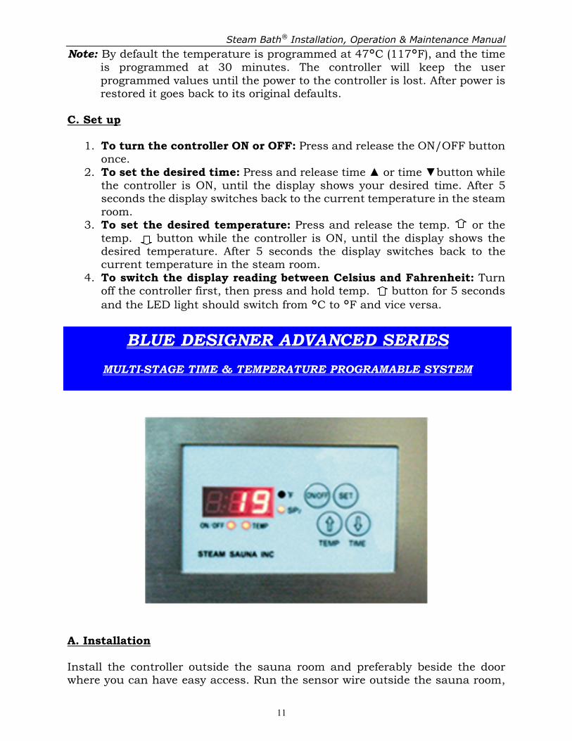
A. Installation
Install the controller outside the sauna room and preferably beside the door where you can have easy access. Run the sensor wire outside the sauna room,
and then insert the probe into the room. The best location for sensor is 5” above the door level and the sensor tip should be exposed 1.5” into the room. Note: The controller is provided with a standard length of 15 ft connector cable
and 20ft sensor cable. If you need to extend them up to 50 ft, use RG3 or RG5 cables or 2 pairs cable (22 to 18 AWG).
B. Operation
The controller can be programmed for 2 different temperature setpoints and 4 different time settings.
1. Temperature control: Controls the temperature setpoint in sauna room,
which can be set from 0°C to 99°C (32°F to 210°F). It can be set for 2 different values, SP1 and SP2. To switch between SP1 and SP2, just press the TEMP button once while the control is turned on.
Example: Lily uses SP1 and sets it for 75°C, but Brian who uses SP2, likes it a
bit hotter, so he sets SP2 for 80°C. 2. Time control: Controls the duration of sauna heater operation, which can
be set from 1 to 240 minutes. The unit will work until it times out. It can be set for 4 different values; t1, t2, t3 and t4. To switch between t1 and t2, press the TIME button once then press SET button while the control is turned on.
Example: Lily takes a short sauna bath, so she uses t1, which is set for 30 minutes. But Brian enjoys it a bit longer, so he uses t2, which is set for 45 minutes and so on. 3. ON/ OFF: Turns ON or OFF the sauna heater. When the control is turned
on, the ON/OFF light stays on. When the control is in standby mode the ON/OFF light stays off, but the °F light stays on. Before the time goes off, the indicator light will blink for 1 min, during this period, you can push the Time button to repeat the session again.
4. Temperature display: Displays the current temperature of the steam room in Celsius or Fahrenheit. The temperature reading on the display can be changed from Celsius to Fahrenheit and vice versa. To switch the display reading between Celsius and Fahrenheit: First turn off controller by pushing ON/OFF button, press the and buttons together for 5 seconds, and the display shows the C or F for 3 seconds.
Note: By default the temperature is programmed at SP1=47°C (117°F),
SP2=50°C (122°F); The time is programmed at t1=30 min, t2=45 min, t3=60min, t4=90min. The controller will keep the user programmed values in memory.
1. To change the default setting: Press and hold the SET button for 3 seconds while the controller is ON, it will show the value in SP2. Press the button or to set the desired temperature. Then press the SET button to move to the next setpoint SP1 and use the and buttons to change its value. Press the set button again and repeat the same sequence to change the settings for t1, t2, t3 and t4.
Use this steam unit as the factory set it up. Modify it only on recommendation from the manufacturer. NEVER add valves or other controls to the steam line. To do so may cause equipment failure or personal injury. If control devices other than those approved by the manufacturer are added to the steam line, the warranty will be null and void. For all models, please note the following steps: A. When you need to shut down the power –
1. Turn off the unit at the timer; 2. Wait for 15-30 seconds; 3. Shut down the main power supply.
Failure to do this may cause the microprocessor to malfunction.
���� Exceptions: Power failures or emergency.
If the unit has lost power and is not operating correctly, follow the shut down procedure but leave the power turned off for a minimum of 10 min. This will allow overcharged capacitors to drain off excess charge.
B. To start it again - 1. Turn on the power at the panel; 2. Then turn on the timer.
Calcium and other mineral deposits are your steam generator’s worst enemy. The factory installed a sediment filter on the incoming water supply line is imperative. However, a secondary filtration system to reduce or remove these components from the water prior to its entering the unit will not only extend time between service calls, it will extend the life of your unit. There are many filter options available as secondary filters. These will reduce or even eliminate the mineral buildups within the tank.
Water Softener or Reverse Osmosis (R.O.) System Either of these systems is ideally suited as a secondary system. However, even if there is a water softener set up on the house water other than R.O. System, it is set up to accommodate only the heating of water and not the boiling of water. A secondary small softener dedicated to the steam generator is generally recommended. It will need to be set up slightly differently than the house softener so that it strips all mineral impurities from the water.
Several options are available that may enhance the use of your Steam Bath®. All Steam Bath® steam units incorporate a microprocessor that utilizes state of the art technology. “Auto Flush” Series units have an added benefit of helping to keep the unit clean.
Auto Flush System
Drain system is an option that can be provided with either a manual shut off valve or an automatic solenoid valve. After each use, the unit drains automatically. It drains out the water together with suspended minerals and other impurities. This helps to minimize the buildup inside the tank, greatly reducing servicing. When you have finished your bath, the unit shuts down, and after 2 minutes, drains, then remains in a standby mode ready for the next use.
This is the top of the line system for your home. Combine a “Four-in-One” Digital Timer with your unit and your steam bath will be ready when you want it. This module comes with a temperature sensor, which controls the temperature in steam room. The built-in thermostat will hold the room at your desired temperature. When linked with our “Four-in-One” Digital Control Module, you can simply program, and forget it (see page 8 for more details).
In Room Electronic Touch Timer This system gives you more control over the steam output. You can turn on and off the steam from inside the steam room at your wish. It is an electronic timer (30 minutes auto shut off) with ON/OFF switch and indicator light that allows you to control the steam density in your steam room.
Air Switch
As an added feature, you may wish to install an air switch. This will allow you to stop or start the steam output while inside the steam room. It is a convenient feature that allows you to control the steam density in your steam room. It operates similar to “In Room Touch Timer”, the only difference is that it’s pneumatic and doesn’t need power cable, but uses a small air tube.
Thermostat
To maintain your ideal temperature, a digital thermostat is available (not used with the “Four-in-One” Digital Timer). It can automatically control the temperature in the steam room and comes with a sensor. If you are going to be using your steam room for more than ½ hour at a time, this will maintain your ideal temperature without overheating the room.
24 Hour Timer
For frequent users who may use the unit more than 30 minutes daily, a 24 hour timer can be installed on the unit when required. It automatically turns on the unit at desired time and shuts off the unit by the end of a day. Both ON and OFF times can be set by the user.
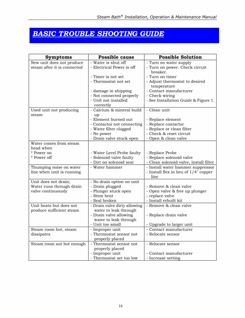
Symptoms Possible cause Possible Solution New unit does not produce steam after it is connected
- Water is shut off - Electrical Power is off - Timer is not set - Thermostat not set - damage in shipping - Not connected properly - Unit not installed
correctly
- Turn on water supply - Turn on power. Check circuit
breaker. - Turn on timer - Adjust thermostat to desired
temperature - Contact manufacturer - Check wiring - See Installation Guide & Figure 1.
Used unit not producing steam
- Calcium & mineral build up
- Element burned out - Contactor not connecting - Water filter clogged - No power - Drain valve stuck open
- Clean unit - Replace element - Replace contactor - Replace or clean filter - Check & reset circuit - Open & clean valve
Water comes from steam head when * Power on * Power off
- Water Level Probe faulty - Solenoid valve faulty - Dirt on solenoid seat
The manufacturer warrants each part to be free from defects in material and workmanship, in the course of normal use and agrees to repair or exchange any part thereof in which such defects appear, to the satisfaction of the manufacturer. This warranty is applied within the boundaries of the United States or Canada. The manufacturer’s obligation under this warranty is limited to the repairing or exchanging of any defective part, if that part is returned to the manufacturer. Postage and handling charges to and from Steam Sauna Inc for warranty repairs is to be prepaid by the purchaser. A return authorization number assigned by Steam Sauna Inc is required prior to returning any product for repair. Components returned without a return authorization number will not be repaired or replaced. Any missing parts claim must be made within 48 hours of receiving this product. This warranty does not cover any related charges for the installation/removal of these products. Warranty service can be obtained by sending your product to Steam Sauna Inc. Proof of purchase and a serial number of the product will be required before any services are performed. This warranty applied only to the original purchaser. For all residential steam units, the boiling tank is protected by a full five-year warranty against corrosion and leakage. You have a one-year warranty on all components including parts and labor from date of purchase (return freight and all “on site” work is purchaser’s obligation). If used for light duty commercial application this warranty will be limited to a full 120 days from the date of purchase with one-year on the boiling tank against corrosion and leakage. The manufacturer’s obligation under this warranty is limited to those products for which a fully completed warranty registration card is returned to the manufacturer, within thirty days of purchase, accompanied by a copy of the proof of purchase, evidencing the purchase date of the said product; failing which this warranty shall not apply.
The warranty is void if a certified plumber, electrician or authorized qualified service representative do not perform the installation and wiring.
This warranty does not apply to any product, which has been repaired or altered in any way, so as in the judgment of the manufacturer to injure the product’s stability or reliability or which has been subjected to misuse, neglect, accident or any use other than steam bath. Neither does this warranty applies to any product connected, installed or adjusted other than in accordance with the manufacturer’s instruction, or if the steam line(s) are restricted in any manner. The manufacturer will not be liable to you or anyone else for any damages, loss of profits, loss of earnings, loss of business opportunities, personal injury or other loss resulting directly or indirectly from using the equipment or services. This warranty is in lieu of any other warranties expressed or implied and no representative is authorized to assume for the manufacturer any liability in conjunction with the sale of the manufacturer’s products.