69


M V M Mobility Vehicle Mechanics
Editors: Prof. dr Jovanka Lukić; Prof. dr Čedomir Duboka
MVM Editorial Board
University of Kragujevac
Faculty of Engineering
Sestre Janjić 6, 34000 Kragujevac, Serbia
Tel.: +381/34/335990; Fax: + 381/34/333192
Prof. Dr Belingardi Giovanni
Politecnico di Torino,
Torino, ITALY
Dr Ing. Ćućuz Stojan
Visteon corporation,
Novi Jicin,
CZECH REPUBLIC
Prof. Dr Demić Miroslav
University of Kragujevac
Faculty of Engineering
Kragujevac, SERBIA
Prof. Dr Fiala Ernest
Wien, OESTERREICH
Prof. Dr Gillespie D. Thomas
University of Michigan,
Ann Arbor, Michigan, USA
Prof. Dr Grujović Aleksandar
University of Kragujevac
Faculty of Engineering
Kragujevac, SERBIA
Prof. Dr Knapezyk Josef
Politechniki Krakowskiej,
Krakow, POLAND
Prof. Dr Krstić Božidar
University of Kragujevac
Faculty of Engineering
Kragujevac, SERBIA
Prof. Dr Mariotti G. Virzi
Universita degli Studidi Palermo,
Dipartimento di Meccanica ed
Aeronautica,
Palermo, ITALY
Prof. Dr Pešić Radivoje
University of Kragujevac
Faculty of Engineering
Kragujevac, SERBIA
Prof. Dr Petrović Stojan
Faculty of Mech. Eng. Belgrade,
SERBIA
Prof. Dr Radonjić Dragoljub
University of Kragujevac
Faculty of Engineering
Kragujevac, SERBIA
Prof. Dr Radonjić Rajko
University of Kragujevac
Faculty of Engineering
Kragujevac, SERBIA
Prof. Dr Spentzas Constatinos
N. National Technical University,
GREECE
Prof. Dr Todorović Jovan
Faculty of Mech. Eng. Belgrade,
SERBIA
Prof. Dr Toliskyj Vladimir E.
Academician NAMI,
Moscow, RUSSIA
Prof. Dr Teodorović Dušan
Faculty of Traffic and Transport
Engineering,
Belgrade, SERBIA
Prof. Dr Veinović Stevan
University of Kragujevac
Faculty of Engineering
Kragujevac, SERBIA
For Publisher: Prof. dr Miroslav Živković, dean, University of Kragujevac, Faculty of
Engineering
Publishing of this Journal is financially supported from:
Ministry of Education, Science and Technological Development, Republic Serbia

Mobility & Motorna Vehicle Vozila i Mechanics Motori _____________________________________________________________
Aleksandar Peulić Željko Jovanović
SMART SYSTEM FOR VEHICLE COMFORT MONITORING AND ACTIVE SUSPENSIONS CONTROL
1-14
Perić Sreten Nedić Bogdan Stoiljković Mile Antunović Ranko
THE ANALYTICAL COMPOSITION OF THE BIODEGRADABLE UNIVERSAL TRACTOR OIL BASED ON THE VEGETABLE OILS
15-27
Snežana Petković Valentina Golubović Bugarski Zeljko Djurić Branko Miladinović
IMPROVEMENT OF VEHICLE INSPECTION TECHNOLOGY BY INTRODUCING INTEGRATED INFORMATION SYSTEM
29-39
Marko Denić Zorica Đorđević Vesna Marjanović Nenad Petrović Nenad Kostić
COMPARATIVE COMPOSITE AND CONVENTIONAL DRIVE SHAFT ANALYSIS
41-50
Slobodan Mišanović DETERMINATION THE NORMS OF FUEL CONSUMPTION FOR BUSES IN THE PUBLIC TRANSPORTATION IN REAL CONDITIONS OF EXPLOITATION
51-65
Volume 42 Number 4
2016.
Mobility & Motorna
Vehicle Vozila i Mechanics Motori
Aleksandar Peulić Željko Jovanović
PAMETNI SISTEM ZA MERENJE UDOBNOSTI VOZILA I AKTIVNU KONTROLU VEŠANJA
1-14
Perić Sreten Nedić Bogdan Stoiljković Mile Antunović Ranko
ANALITIČKA KOMPOZICIJA BIORAZGRADLJIVIH UNIVERZALNIH TRAKTORSKIH ULJA NA BAZI BILJNIH ULJA
15-27
Snežana Petković Valentina Golubović Bugarski Željko Djurić Branko Miladinović
UNAPREĐENJE TEHNIČKOG PREGLEDA VOZILA UVOĐENJEM INTEGRALNOG INFORMACIONOG SISTEMA
29-39
Marko Denić Zorica Đorđević Vesna Marjanović Nenad Petrović Nenad Kostić
KOMPARATIVNA ANALIZA KOMPOZITNOG I KONVENCIONALNOG KARDANSKOG VRATILA
41-50
Slobodan Mišanović
ODREDJIVANJE NORMATIVA POTROŠNJE GORIVA ZA AUTOBUSE U JAVNOM GRADSKOM PREVOZU U REALNIM USLOVIMA EKSPLOATACIJE
51-65
Volume 42 Number 4
2016.

Volume 42, Number 4, 2016
SMART SYSTEM FOR VEHICLE COMFORT MONITORING AND
ACTIVE SUSPENSIONS CONTROL
Aleksandar Peulić, Željko Jovanović1
UDC:629.113;534.015.1
ABSTRACT: Passengers’ comfort is one of the most important characteristics of vehicles.
Several aspects affects on it but suspension system is most important. Suspension systems
demands include a high level balance between comfortable ride, excellent high speed
directional stability and cornering performance. These demands are high and sometimes
unattainable for passive suspension systems. Active suspension system can solve the
problem by affecting on suspension characteristics according to real time measured driving
conditions. In this paper, the device for control and prediction of the suspension is proposed.
It is based on the “quarter car” model with the observer, designed to reconstruct the
immeasurable states from the available output measurement.
KEY WORDS: active suspension system, Android, optimal control, reduced-order observer
PAMETNI SISTEM ZA MERENJE UDOBNOSTI VOZILA I AKTIVNU
KONTROLU VEŠANJA
REZIME: Udobnost putnika je jedna od najvažnijih karakteristika vozila. Nekoliko
aspekata utiču na udobnost ali sistemi vešanja su najvažniji. Projektovanje sistema vešanja
zahteva balans između udobne vožnje, odlične upravljivosti pri velikim brzinama i
skretanju. Ovi zahtevi su veoma veliki i ponekad nemogući za pasivne sisteme vešanja.
Aktivni sistemi vešanja mogu da reše ovaj problem uticajući na karakteristike sistema
vešanja u realnom vremenu u zivisnosti od uslova vožnje. U ovom radu, sistem za kotrolu i
predikciju vešanja je predložen. Zasnovan je na „četvrtinskom“ modelu vozila sa
observerom, dizajniran da rekonstruiše nemerljiva stanja na osnovu dostupnih rezultata
merenja.
KLJUČNE REČI: aktivna kontrola vešanja, Android, optimalna kontrola, redukovani
observer
1 Received: October 2016, Accepted November 2016, Available on line December 2016

Intentionally blank

Volume 42, Number 4, 2016
SMART SYSTEM FOR VEHICLE COMFORT MONITORING AND
ACTIVE SUSPENSIONS CONTROL
Aleksandar Peulić 1, Željko Jovanović
2
UDC:629.113;534.015.1
1. INTRODUCTION
Vehicle movement over random road surface produces oscillations that impact
on passengers and a vehicle. Generally, it is accepted that the vibrations which
passengers feel during the ride has the greatest impact on passenger comfort. This field
is known as whole-body vibration (WBV). Current standards and regulations for WBV
are defined in:
ISO standard 2631–1 (1997), [1]
British Standard 6841 (1987), [2]
ANSI S3.18:2002 [3]
European Directive 2002/44/EC [4]
The Control of Vibration at Work Regulations [5].
An overview of current standard and regulations is presented in [6]. The
International Standard Organization (ISO) presents a criterion for ride comfort evaluation
(ISO 2631) [1] which describes the effects of vibrations on a person.
Both standards and regulations assume that acceleration magnitude, frequency
spectrum, and duration represent the principal exposure variables, which account for the
potential harmful effects. At the national level in Serbia there is standard ICS 13.160 (SRPS
ISO 2631-1:2014 Mechanical vibration and shock: Evaluation of human exposure to whole-
body vibration, Part 1: General requirements). Besides vibration exposure, duration and
direction of a vibration exposure are important for passengers comfort. According to the
ISO 2631-1 standard [1], whole-body vibration exposure is a health risk. Many jobs are
exposed to vibrations. Authors of [7] use ISO 2631 standard method for whole-body
vibration exposure in comfort determination for haulage truck operators in surface mining
operations. They showed that workers were exposed to WBV levels that exceeded safety
limits, as dictated by the ISO 2631-1 standard. The authors of [8] showed little match
between ISO 2631-1 comfort prediction results and self-reported results during heavy
machinery routines for construction, forestry, and mining vehicles. In [9] authors presented
a high correlation between whole-body vibration exposure and disability pension retirement,
while the authors of [10] concluded that mechanical vibrations affects more on older and
lighter drivers .
There are two ways to reduce the oscillations. First one is to build good quality
roads, and the second one is development of the suspension systems. Classic suspension
systems, produced only with the springs and shock absorbers, cannot change their
1 Aleksandar Peulić, Assist. prof., University of Kragujevac, Faculty of Engineering, Serbia, Sestre
Janjić 6, 34000 Kragujevac, [email protected] 2 Željko Jovanović, Teaching assist., University of Kragujevac, Faculty of Technical Sciences, Čačak,
Serbia, Svetog Save 65, 32000 Čačak, [email protected]

Aleksandar Peulić, Željko Jovanović
Volume 42, Number 4, 2016
4
characteristics during the transport. They are created to produce compromise between
comfort and vehicle stability.
Linear optimal control [11] is part of the modern control theory which enables the
design of specific types of analytical systems. This is applied in [12, 13] for the optimal
design of active vehicle suspension system based on the use of the feedback loop. In [12]
active suspension system is realized by using multivariate interactive PI control. Problem
with this method it that it is necessary to measure suspension stroke, tire stroke and speed of
a suspended and unsuspended mass. In [13] is designed regulator with full observer, which
in the feedback use estimated states instead the real ones. Measurement of only one
parameter, suspension stroke, is needed. By enabling integrators in the feedback loop, per
output, by including the state variable which represent the integral of the output (ie. the
suspension stroke) of the system, the prime response output in a stationary mode, at constant
excitation force acting on the suspended mass and the input from the road surface is
achieved.
Nowadays, accelerometers and GPS are part of almost every smart phone. This is
the main reason for becoming interesting as mobile sensing devices. Mobile technologies
may have the potential in becoming the leader of data gathering in this field. Paper [14]
described a mobile sensing system for road irregularity detection using Android OS-based
smartphones. Paper [15] considered the problem of monitoring road and traffic conditions in
a city using smartphones.
This paper describes the design of the controller which is based on an approach
[13], except estimation of the measurable state variable. For testing purposes smart system
for acceleration measurement in form of Android application is developed. Nowadays,
accelerometers, gyroscope and GPS are part of almost every smart phone. This is the main
reason they are becoming interesting as mobile monitoring devices in transportation. The
authors of [3] used high-pass filtered accelerometer data in order to detect road potholes.
Paper [6] described a mobile sensing system for road irregularity detection using Android
OS-based smartphones. Paper [7] also considered the problem of monitoring road and traffic
conditions in a city using smartphones. For simulation, two scenarios are created: “ramp” –
hitting the surface with angle slope, “step” – hitting the curb.
2. FORMULATION OF THE PROBLEM
We will assume that the active suspension system contains conventional elements
(spring and shock absorber) with hydraulic or electro-hydraulic actuator. We look at a
simplified, linear "quarter car" model of vehicle presented on the Figure 1. For this model
and its dynamic environment, we define the differential matrix equation:
ZwbuAxx (1)
where the system matrix are:

Smart system for vehicle comfort monitoring and active suspensions control
Volume 42, Number 4, 2016
5
2
2
2
2
2
2
1
2
1
2
1
1
1
2
0
0100
1100
mmm
mmmmA
bm
m
0
01
11
2
(2)
2
10
00
01
00
m
Z
wx
f
0
x is the state vector of the fourth order, u is the scalar control force, and w is a vector of
input.
Figure 1 A quarter-car model of suspension system
The output of the system is one variable, suspension stroke:
Cxy where c is: 0001C (3)
Also, it is necessary to neutralize the constant impact of the system disorders vector
w (static force f acting on the suspended weight and "ramp" from the road surface) in
stationary mode.
Therefore, it is necessary to expand the state vector of the system (1) and introduce
a new state variable, g(t):

Aleksandar Peulić, Željko Jovanović
Volume 42, Number 4, 2016
6
g y
(4)
which represents the integral of the output (3) of the system. Extended system can be
described with matrix equations:
xCy
wZubxAx
~~
~~~~~
(5)
where the matrix and vectors are formed in the following manner:
0~
0
~
0
~
0
0~~ CCZ
Zb
bC
AA
g
xx
(6)
3. OPTIMAL LINEAR CONTROL
Selection of the Riccati state controller for solving problems of optimization of the
complete system provides the analytical solution with a relatively short period of time
necessary for the design and calculation. This type of controller takes, calculates and return
system state, which is an advantage over some classic regulator structures.
By minimizing the linear quadratic performance index leads to the law of control in
a closed loop by state. For expanded system (5) performance index penalizes non-zero status
and management, ie. takes into account the limited suspension workspace, stability of the
vehicle on the road and ride comfort of passengers.
In matrix form, the performance index is given by the equation:
J x Qx u dtT
1
2
2
0
~ ~
(7)
where is:
Q
q
q
q
1
2
3
0 0 0 0
0 0 0 0
0 0 0 0 0
0 0 0 0 0
0 0 0 0
(8)
Different choice of weights coefficients in the index performance (7) can provide
different control, ie. different system performance. By solving Riccati algebraic matrix
equation:
0~~~~ 1 QPbbPPAAP TT (9)
which solution is symmetric positive definite matrix P, we get the optimal control equations:

Smart system for vehicle comfort monitoring and active suspensions control
Volume 42, Number 4, 2016
7
u b PxT 1~ ~
(10)
and row-matrix of the Kalman amplification in the feedback is:
K b PT 1~
(11)
and can be divided into proportional and integral amplification:
K K Kp i
(12)
so that the control rules (10) can be written in the form:
u K x K gp i
(13)
It is easy to show that the system is in closed loop (when all states are measurable),
~ ~ ~ ~ ~x A bK x Zw
(14)
asymptotically stable.
4. REDUCED OBSERVER
In the case of a system in which all states measurements are not available in a
simple and easy way, very often the state observer is projected that estimate the state of the
system based on the measurement and control of outputs [4]. Estimated states are used
instead of the real ones for obtaining control (13), which is justified by the separation
theorem [1].
In the adopted model, Figure 1, is a fourth order system with the one measurable
state variable so is necessary to design a reduced third-order observer [5]. For ease of
performing a mathematical relationship, we will simply break down the state vector on:
x x x x x xT
1 2 3 4
(15)
and system matrixes (2), so we have:
x A x A x b u Z w
x A x A x b u Z w
11 12 1 1
21 22 2 2
(16)
Vector of the estimated states is defined by the equation:
x h Lxe (17)
where h is new 3-dimensional state vector system, and L is the amplifying vector of the
reduced observer which need to be calculated. By swapping (17) in (16) instead of the x ,
and eliminating disturbance vector, we obtained:

Aleksandar Peulić, Željko Jovanović
Volume 42, Number 4, 2016
8
h A x A LA x b ue 21 22 12 2
(18)
Figure 2 shows the way of designing the reduced observer. Control is given by
equation:
u K x K x K gp p e i
(19)
where KP is:
K K Kp p p
(20)
Figure 3 shows the realization of complete systems with closed feedback loop.
h xe u h
x y
+ +
L A21
b2
A22-LA12
Figure 2 Generating of the immeasurable estimated states
Figure 3 System with the closed feedback loop
Estimation error of the immeasurable states is denoted by the:
exx (21)

Smart system for vehicle comfort monitoring and active suspensions control
Volume 42, Number 4, 2016
9
then from the equations (16) and (17), by subtracting and using equation (18), we get the
differential equation for the estimation errors (21):
A LA Z w22 12 2 (22)
According to the separation characteristic, set of values consists of the system
values and the reduced observer values which are zeros sir , i=1,2,3, of polynomial:
0det 1222 LAAsI (23)
arbitrarily are set by selecting the appropriate amplifying value of the reduced observer.
If we assume that the system does not operate with disorders and if self-worth
values of the observer (23) have negative real parts, error estimation (21), (22) will tend to
zero according to an exponential law, and xe will follow the x after a certain time
(which depends on the observer's values). At first glance, it is best to choose such observer
amplification L that the observer's own values have high negative real parts:
Re Res sir js 0 (24)
where s js , j=1..4 are own system values (14), ie. zero polynomial:
0det pbKAsI (25)
because then estimated sheet (17) start to follow real states (15), as fast as possible. But,
from the other side, higher observer values, in the left half plane, the bandwidth of the
observer is higher, and the effect of measurement noise is higher on the result of estimation.
Thus, the impact of noise on the measurement system that determines the upper limit of the
speed with which the estimated states can approach to the real states. Therefore, the design
of the observer consists in seeking and finding a compromise between the estimation speed
and performance loss due to noise on the measurement system.
5. ANDROID APPLICATION
Android application is developed to monitor transport parameters using
accelerometer and GPS (for storing location). Main application functionalities are developed
using RxJava [17] for accelerometer calculations, GPS monitoring, and main application in
the separate threads. The developed Android application algorithm is presented in Figure 4.
After application parameters setup, the accelerometer and GPS threads start. Next
step is accelerometer calibration, and after that, the comfort calculation is performed. During
calculations, the accelerometer axis live signals are plotted on the phone display. After the
decision time interval has passed, the user needs to choose subjective comfort level
(comfortable, little uncomfortable, and very uncomfortable). Calculated data are stored to
files while new calculations starts in the background.

Aleksandar Peulić, Željko Jovanović
Volume 42, Number 4, 2016
10
Figure 4 Algorithm of usage for the developed Android application
In order to measure the dynamic accelerations of the device, the influence of the force of
gravity must be eliminated. This is achieved by applying a high-pass filter over raw
accelerometer data, according to equation (26):
) )) (26)
where HPXi is the i-th high-pass-filtered X axis acceleration, RX is raw X axis acceleration
data, and fc=0.1 is the filter coefficient that cuts the 10% of the lower frequencies. Raw and
filtered data for all three axes are presented in Figure 5.
Figure 5 Raw and high-pass-filtered accleration data for all three axes: (a) raw XYZ; (b)
high pass XYZ

Smart system for vehicle comfort monitoring and active suspensions control
Volume 42, Number 4, 2016
11
As presented in Figure 5 the gravity influence is eliminated without loss of informations.
Since the phone was almost in an ideal vertical position the gravity impact was largest on
the Z axis. The calculation is performed over high-pass-filtered data for the all three axes.
For simulation purposes, smartphone (processor 1.2GHz, Android OS v4.2,
accelerometer, GPS) with running application is attached to the windshield using the
navigation holder which is presented on Figure 6 a). At this position, suspended mass
acceleration is measured. The accelerometer sampling is set to 20ms. Live accelerometer
axis signals are plotted on the phone display and stored to files for further analysis. Over
vertical (Z) axis calculation (26) is performed in order to calculate interval accumulated
vibrations:
√
)
(27)
where n is number of samples, azi is Z axis acceleration. During driving locations are saved
to KML files, suitable for viewing in GIS software like Google Earth. Marker color
represent accumulated vibration level in 10s interval (green < 0.33[m/s2], 0.33[m/s
2] <=
yellow < 0.66 [m/s2], red >= 066[m/s
2]). Figure 6 b) shows accumulated vibration on Cacak-
Uzice relation. Real time calculations were performed beside standard smartphone
functions.
a) b)
Figure 6 Implemented application usage, a) smartphone position, b) created KML file on
Cacak-Uzice relation
6. RESULTS AND CONCLUSIONS
In numerical calculations for the “ramp” and “step” test cases the following values
are used:
m1=28.58 kg, m2=288.9 kg, 1=155900 N/m, 2=19960 N/m, 2=1861.9 Ns/m.
With numerous simulations of systems using different selection of weighting
coefficients for the index performance (7) and by result analysis next values are chosen:
q1=1, q2=10, q3=5, =2*10-10
.
By calculating the Riccatti equation (9) amplification is calculated:
K= [-70452 87718 -961 6917 -158110].

Aleksandar Peulić, Željko Jovanović
Volume 42, Number 4, 2016
12
Because system values are (14): -2.14, -6.47j9.79, -57.02j82.84 according to (24) and the
problem of measurements noise with large system bandwidth, we will adopt next reduced
observer values: sir 80 , i=1, 2, 3. By solving (23) amplification of the reduced
observer is calculated: L= [2.52 81.02 -87.42]T.
At the Figure 5 and Figure 6 responses of the suspension with observer (all states
measurable) for excitation "ramp" and the "step" from the road surface, respectively, are
shown. It can be seen that the system with the observer has a smaller peak, but in a response
to "ramp" negative leap occurs as a result of the new arrangement of zeros and poles of the
system. Also, the system response with reduced observer is not significantly better than the
response of the system with full observer [4].
Figure 7 The response of the suspension for the "ramp" from the road surface
Figure 8 The response of the suspension for the "step" from the road surface

Smart system for vehicle comfort monitoring and active suspensions control
Volume 42, Number 4, 2016
13
Considering the extremely high sensitivity of the system with reduced observer on
noise measurement, we can conclude that the system should be developed with the full
observer [4]. Reduced observer in the estimation of the immeasurable states is used less than
complete observer because of the output measurement noise (which is random, Gaussian,
and which is unavoidable), is not filtered and is even more amplified and directed into the
system, as shown in Figure 3. The use of the reduced observer should be avoided because it
is better to increase the system with the regulator rather than introducing the system with too
big noise.
ACKNOWLEDGMENT
The work presented in this paper was funded by grant no. TR32043 for the period
2011-2016 from the Ministry of Education and Science of the Republic of Serbia.
REFERENCES
[1] ISO 2631-1:1997 - Mechanical vibration and shock -- Evaluation of human exposure
to whole-body vibration -- Part 1: General requirements, (n.d.).
http://www.iso.org/iso/home/store/catalogue_tc/catalogue_detail.htm?csnumber=7612
(accessed September 8, 2015).
[2] BSI, BS 6841:1987 Guide to measurement and evaluation of human exposure to
whole-body mechanical vibration and repeated shock, BSI. (1987).
http://www.mendeley.com/catalog/bs-68411987-guide-measurement-evaluation-
human-exposure-wholebody-mechanical-vibration-repeated-shoc/ (accessed
September 9, 2015).
[3] ASA S2.72-2002/Part 1 / ISO 2631-1:1997 (R2012), (n.d.).
http://www.techstreet.com/products/1508686 (accessed September 9, 2015).
[4] Directive 2002/44/EC - vibration - Safety and health at work - EU-OSHA, (n.d.).
https://osha.europa.eu/en/legislation/directives/19 (accessed September 9, 2015).
[5] Hand arm vibration - Control of Vibration at Work Regulations 2005, (n.d.).
http://www.hse.gov.uk/vibration/hav/regulations.htm (accessed September 9, 2015).
[6] Whole-Body Vibration Building Awareness in SH&E, (n.d.).
http://www.asse.org/assets/1/7/030_035_F1Paschold_0411Z.pdf (accessed September
8, 2015).
[7] M.P.H. Smets, T.R. Eger, S.G. Grenier, Whole-body vibration experienced by haulage
truck operators in surface mining operations: A comparison of various analysis
methods utilized in the prediction of health risks, Appl. Ergon. 41 (2010) 763–770.
doi:10.1016/j.apergo.2010.01.002.
[8] K. Plewa, T.R. Eger, M.L. Oliver, J.P. Dickey, Comparison between ISO 2631-1
Comfort Prediction Equations and Self-Reported Comfort Values during Occupational
Exposure to Whole-Body Vehicular Vibration, J. Low Freq. Noise, Vib. Act. Control.
31 (2012) 43–53. doi:10.1260/0263-0923.31.1.43.
[9] F. Tüchsen, H. Feveile, K.B. Christensen, N. Krause, The impact of self-reported
exposure to whole-body-vibrations on the risk of disability pension among men: a 15
year prospective study., BMC Public Health. 10 (2010) 305. doi:10.1186/1471-2458-
10-305.

Aleksandar Peulić, Željko Jovanović
Volume 42, Number 4, 2016
14
[10] H. Ayari, M. Thomas, S. Dor, A design of experiments for statistically predicting risk
of adverse health effects on drivers exposed to vertical vibrations, Int. J. Occup. Saf.
Ergon. 17 (2011) 221–232. doi:10.1016/j.aca.2010.11.024.
[11] B.D.O. Anderson, J.B. Moore, Optimal Control : Linear Quadratic Methods, 1989.
http://mirlyn.lib.umich.edu/Record/001956608.
[12] M.M. ELMADANY, Optimal Linear Active Suspensions with Multivariable Integral
Control, Veh. Syst. Dyn. 19 (1990) 313–329. doi:10.1080/00423119008968950.
[13] S. Jovanović, M. Ravlić, Design of A Vehicle Active Suspension System, in: 8th
Symp. MVM, 1994: pp. 19–24.
[14] A. Mednis, G. Strazdins, R. Zviedris, G. Kanonirs, L. Selavo, Real time pothole
detection using Android smartphones with accelerometers, in: 2011 Int. Conf. Distrib.
Comput. Sens. Syst. Work. DCOSS’11, 2011. doi:10.1109/DCOSS.2011.5982206.
[15] P. Mohan, V.N. Padmanabhan, R. Ramjee, TrafficSense : Rich Monitoring of Road
and Traffic Conditions using Mobile Smartphones, 6th ACM Conf. Embed.
Networked Sens. Syst. (2008) 1–29. doi:MSR-TR-2008-59.
[16] J. Eriksson, L. Girod, B. Hull, R. Newton, S. Madden, H. Balakrishnan, The Pothole
Patrol: Using a Mobile Sensor Network for Road Surface Monitoring, Proc. 6th Int.
Conf. Mob. Syst. Appl. Serv. (2008) 29–39. doi:10.1145/1378600.1378605.
[17] ReactiveX, (n.d.). http://reactivex.io/ (accessed October 5, 2015).

Volume 42, Number 4, 2016
THE ANALYTICAL COMPOSITION OF THE BIODEGRADABLE
UNIVERSAL TRACTOR OIL BASED ON THE VEGETABLE OILS
Perić Sreten1, Nedić Bogdan, Stoiljković Mile, Antunović Ranko
UDC:665.334.9;621.892
ABSTRACT: The basic function of the lubricant is the lubrication i.e. the diminishing of
the friction between two surfaces in relative motion. Besides, they are also used to transfer
power, heat transfer, cooling, corrosion protection and so on. Lubricating oils and greases
are the third tribology element and their use is necessary for the proper function of almost
every mechanical system. This paper presents development and testing of the biodegradable
universal tractor oil based on the vegetable oils. The agricultural equipment is ideal for the
use of biodegradable oils based on vegetable oils because it is used in the very proximity of
the environment where the lubricant can come into contact with the soil, water and crops.
This is the ideal opportunity to create permanent cycle where the agricultural equipment is
lubricated by the oil from the plants grown in the fields cultivated by the very same
equipment. Universal tractor oil (UTTO) is the multipurpose oil for the lubrication of the
transmission, rear axle, differential, wet brakes, and hydraulic system fed by the common oil
reservoir.
KEY WORDS: biodegradable universal tractor oil, oil analysis, physic chemical properties
ANALITIČKA KOMPOZICIJA BIORAZGRADLJIVIH UNIVERZALNIH
TRAKTORSKIH ULJA NA BAZI BILJNIH ULJA
REZIME: Osnovna funkcija maziva je podmazivanje, odnosno smanjenje trenja između
dve površine koje su u relativnom kretanju. Osim toga koriste se i za prenos snage, prenos
toplote, hlađenje, zaštitu od korozije itd. Maziva ulja i masti su treći tribološki element i
njihova upotreba je neophodna za pravilno funkcionisanje skoro svih mehaničkih sistema. U
radu je prikazan razvoj i ispitivanje biorazgradivih univerzalnih ulja za traktore (UTTO)
biljnog porekla. Poljoprivredna oprema je idealna za upotrebu biorazgradivih ulja na bazi
biljnih ulja, jer se koristi u neposrednoj blizini okoline gde mazivo lako može doći u dodir
sa zemljištem, vodom i usevima. Ovo je idealna prilika za stvaranje trajnog ciklusa u kome
se poljoprivredna oprema podmazuje uljem iz biljke koja raste na polju koje se obrađuje tom
istom opremom. Univerzalno ulje za traktore (UTTO) je višenamensko ulje za
podmazivanje transmisije, zadnjeg mosta, diferencijala, mokrih kočnica i hidrauličnog
sistema sa snabdevanjem iz zajedničkog uljnog rezervoara.
KLJUČNE REČI: biorazgradljivo univerzalno traktorsko ulje, analiza ulja, fizičko
hemijska svojstva
1 Received: November 2016, Accepted November 2016, Available on line December 2016

Intentionally blank

Volume 42, Number 4, 2016
THE ANALYTICAL COMPOSITION OF THE BIODEGRADABLE
UNIVERSAL TRACTOR OIL BASED ON THE VEGETABLE OILS
Perić Sreten 1, Nedić Bogdan
2, Stoiljković Mile
3, Antunović Ranko
4
UDC:665.334.9;621.892
1. INTRODUCTION
Lubricating oils contain up to 80 % of base oils and the properties such as
viscosity, oxidation stability, pour and flash point, volatility and others depend on them.
Lubricating oils can contain up to 20 % additives which improve base oil characteristics or
bring some new properties thus increasing exploitation and technical properties. Lubricants
made out of mineral base oils originating from the crude oil, are the most widely used.
However, these lubricants are very often toxic and are not readily biodegradable, thus being
environmentally aggressive. The annual consumption of lubricants in the world is around 40
million tons out of which less than 40% are collected and properly processed, meaning
regeneration, re-refining and controlled incineration, while the rest is disposed without
control thus contaminating soil, water and atmosphere. It has been proved that 1 liter of
spent oil contaminates 1 million liter of water or one tone of spent oil contaminates the river
water as much as waste water from a 40 000 men town.
Due to the aforementioned potential dangers, during some last twenty years the ecologically
acceptable oils are more and more used. Ecologically acceptable oils are the oils which in
contact with the environment produce the minimum of harmful effects [1-7]. The conditions
for the ecological acceptance are biodegradability and no toxicity of lubricants. Besides,
ecologically acceptable lubes are produced from the renewable sources (vegetable oil) thus
reducing the dependence of mineral oils.
The disadvantages of vegetable oils versus mineral oils are low oxidation stability, low
fluidity on low temperatures, low hydraulic stability and the price which is 1.5 to 2 times
higher than the price of mineral oils [8-13].
The features of oils based on rapeseed oil, sunflower oil, soybean oil and a mixture of
rapeseed oil with mineral oil were, after the corresponding testing, compared with the
features of the commercially available mineral-based universal tractor oil, UTTO (Table 1).
1 Perić Sreten, Ph.D., University of Defence, Military Academy, Pavla Jurišića Šturma Str. No. 33,
11000 Belgrade, Serbia, [email protected] 2 Nedić Bogdan, University of Kragujevac, Faculty of Engineering, 6 Sestre Janjic Street, 34 000
Kragujevac, Serbia, [email protected] 3 Stoiljković Mile, Ph.D., NIS GAZPROMNEFT, Serbia, [email protected] 4 Antunović Ranko, Ph.D.,University of Eastern Sarajevo, Faculty of Mechanical Engineering, 30
Vuka Karadzica Street, 71123 East Sarajevo, BiH, [email protected]

Perić Sreten, Nedić Bogdan, Stoiljković Mile, Antunović Ranko
Volume 42, Number 4, 2016
18
Table 1 Oil Samples
Sample
number Oil name Oil code
1. Rapeseed oil without additives RE
2. Soybean oil without additives SO
3. Sunflower oil without additives SU
4. Rapeseed oil with additives REA
5. Soybean oil with additives SOA
6. Sunflower oil with additives SUA
7. Rapeseed oil + additives + 10% SN150 REAM10
8. Rapeseed oil + additives + 20% SN150 REAM20
9. Mineral UTTO MIN
The ASTM D 4951 and ASTM D 4927 AAS methods have been applied to obtain
the elemental composition of the additives used in the test oils, as shown in Table 2 and
Figure 1.
Table 2 The elemental composition of the additives used in the test oils
P Ca Zn S
% m/m
REA 0.07 0.08 0.13 0.19
SOA 0.06 0.07 0.14 0.19
SUA 0.06 0.07 0.14 0.19
REAM10 0.08 0.15 0.14 0.23
REAM20 0.09 0.18 0.15 0.28
MIN 0.11 0.34 0.15 0.54
Figure 1 The elemental composition of the additives for the test oils

The analytical composition of the biodegradable universal tractor oil based on the
vegetable oils
Volume 42, Number 4, 2016
19
Vegetable oils are generally less additivated than mineral oils, because they possess
good lubricating properties due to their polar nature. This makes them good solvents for
sludge and dirt, which would otherwise deposit on metal surfaces [14-17]. Because of these
properties, it is possible to reduce the amount of friction modifiers, antiwear additive
package, and dispersants, when formulating biodegradable universal tractor oils.
2. PHYSICAL AND CHEMICAL PROPERTIES OF THE TRACTOR OIL
The physical and chemical properties of the vegetable oils were examined in
accordance with standard methods (Table 3).
Table 3 Laboratory test methods
Method
No. Physical and chemical properties Test method
1. Density, kg/m3 ASTM D 1298
2. Kinematic viscosity at 40 C, mm2/s ASTM D 445
3. Kinematic viscosity at 100 C, mm2/s ASTM D 445
4. Viscosity Index ASTM D 2270
5. Pour point, C ASTM D 97 or ISO 3016
6. Flash point, C ISO 2592, ASTM D 92
7. Foaming, ml/ml 24 C; 94 C; 24 C ASTM D 892
8. Deaeration, minutes DIN 51381
9. Oxidation stability, minutes ASTM D 2272
10. Corrosion on copper, 3 hours at 121 °C ASTM D130
11. P content, % ASTM D 4927
12. S content, % ASTM D 2622
13. Ca content, % ASTM D 4628
14. Zn content, % ASTM D 4628
15. Wear, (1h; 65 C; 40 kg and 1500 rpm), mm ASTM D 4172
16. 4-ball EP test - scuffing, kg ASTM D 2783
The results of experimental testing of physico-chemical properties are presented in
Table 4. Experimental work was carried out in accordance with the manufacturer
specifications and proper standards, by using the necessary testing equipment.

Perić Sreten, Nedić Bogdan, Stoiljković Mile, Antunović Ranko
Volume 42, Number 4, 2016
20
Table 4 Physico-chemical properties of oils
Physico-
chemical
properties
Measu
ring
unit
Methods RE SO SU REA SOA SUA REAM
10
REAM
20 MIN
Density at 15°C kg/m³ ASTM
D1298 916 918 920 918 921 922 912 907 877
Kinematic
viscosity at
40°C
mm²/s ASTM D
445 34.8 32.7 35.1 42.3 37.7 38.6 42.0 41.0 70.5
Kinematic
viscosity at
100°C
mm²/s ASTM D
445 7.9 7.82 7.93 9.49 9.17 9.27 9.23 9.18 10.05
Viscosity Index ASTM
D2270 210 224 209 218 227 226 211 201 126
Flash point °C ASTM D
92 322 326 328 254 260 250 248 246 234
Pour point °C ASTM D
97 -8 -13 -11 -23 -25 -24 -26 -27 -36
Foaming,
I sequnce, 24ºC
II sequence,
94ºC
III sequence
24ºC
ml ASTM D
892
0/0
0/0
0/0
0/0
0/0
0/0
0/0
0/0
0/0
25/0
20/0
20/0
15/0
20/0
20/0
30/0
20/0
10/0
25/0
20/0
10/0
20/0
20/0
10/0
5/0
20/0
5/0
Deaeration minute
s
DIN
51381 6 5 6 5 7 1
Oxidation
stability, RBOT
minute
s
ASTM
D2272 13 8 10 109 60 70 120 149 214
Wear,
(1h;75ºC;40kg
and 1200 rpm)
mm ASTM D
4172 0.66 0.69 0.68 0.38 0.39 0.37 0.39 0.39 0.36
4-ball EP test -
scuffing kg
ASTM D
2783 200 200 200 200 160 100
Protection
against
corrosion, Test
B
ASTM D
665 pass pass pass pass pass pass pass pass pass
Corrosion on
copper, 3 hours
at 121 ° C
ASTM
D130 1A 1A 1A 1A 1A 1A 1A 1A 1A

The analytical composition of the biodegradable universal tractor oil based on the
vegetable oils
Volume 42, Number 4, 2016
21
2.1 Kinematic viscosity
Most tractor lubricants possess kinematic viscosity between 9 and 11 mm2/s at 100
°C. This viscosity is found to provide sufficient thickness to promote good protection for the
transmission system and anti-squawk performance, yet still to be a suitable viscosity for the
hydraulic system.
Figure 2 Kinematic viscosity at 40°C, ASTM D 445
As can be seen from Table 4, viscosity of vegetable oils produced from oil seeds
falls between 32,7 and 42,3 mm2/s at 40 °C, and between 7,8 and 9,4 mm
2/s at 100 °C.
Figure 3 Kinematic viscosity at 100°C, ASTM D 445
2.2 Oxidation stability
Most vegetable oils are triglycerides constituting a complex mixture of fatty acids
with different chain length and instauration content [18-24]. The alcohol component
(glycerine) is the same in all vegetable oils. The fatty acid components are plant-specific and
therefore variable. The fatty acids differ in chain length and number of double bonds. From
the fatty acid composition of the oils, it is observed that chain length C18 is dominating
(Table 5). Main fatty acids with double bonds are linolenic, linoleic and oleic. The oxygen
absorption rate is 800:100:1 respectively, therefore less double bonds in a carbon chain
result in better oxidation stability [16]. Generally the oxidation stability of vegetable based
oils decreases with the increased level of instauration.

Perić Sreten, Nedić Bogdan, Stoiljković Mile, Antunović Ranko
Volume 42, Number 4, 2016
22
The content of polyunsaturated fatty acids (C18:2) is rather high for soybean (SO)
and sunflower (SU) oil. Under thermal conditions, the double bonds in polyunsaturated fatty
acids polymerize much faster than monounsaturated (C18:1 and C22:1) or saturated (C16:0
and C18:0) fatty acids. Unfortunately, the saturation of fatty acid degenerates the low
temperature behaviour or pour point of the oil.
Iodine value characterizes particular oil on the base of unsaturated fatty acids. Oils
with high iodine values are more problematic for oxidation processes, however values fewer
than 100 are not recommended since such oils are more problematic for changing the
characteristics at lower temperatures.
Table 5 Fatty acid content and iodine value of vegetable base oil
Physico-chemical properties Unit Rapeseed oil Soybean oil Sunflower oil
Iodine value gI2/100g 118.41 126.2 131.2
Fatty acid content %
C14:0 (Myristic acid) 0.06 0.05 0.04
C16:0 (Palmitic acid) 6.58 10.24 6.35
C16:1 (Palmitoleic acid) 0.36 0.15 0.13
C18:0 (Stearic acid) 2.88 5.24 5.35
C18:1 (Oleic acid) 53.10 29.33 27.13
C18:2 (Linoleic acid) 28.72 47.95 58.53
C18:3 (Linolenic acid) 6.54 5.35 0.16
C20:0 (Arachidic acid) 0.41 0.52 0.41
C20:1 (Eicosenoic acid) 0.73 0.29 0.20
C22:0 (Behenic acid) 0.28 0.65 1.31
C22:1 (Erucic acid) 0.17
C24:0 (Lignoceric acid) 0.10 0.20 0.35
The oxidation stability of oil samples was examined by the ASTM D2272 test
(RBOT - Rotating Bomb Oxidation Test). As concerning the neat vegetable oils (without
additives), rapeseed oil (RE) shows better oxidation stability as compared to the soybean
(SO) and sunflower (SU) oil. The reason is a high content of oleic acid and a low iodine
value present in rapeseed oil. The oxidation stability of vegetable oils without additives is
very low.
The improvement of the oxidation stability of vegetable oils was accomplished by
adding the antioxidant additives and the mineral base oil. The concentration of the additives
was the same for all vegetable oils. The oxidation stability values determined by RBOT
method for neat vegetable oils, vegetable oils with additives and vegetable oils with mineral
base oil, were compared with the values for commercial UTTO oil, as it is shown in Figure
4.
The best oxidation stability shows sample REAM20 (149 minutes). The oxidation
stability is improved by adding the antioxidant additive: for rapeseed oil, the improvement is
more than eightfold. The stability is further increased by adding a mineral oil, but the
biodegradability is reduced.

The analytical composition of the biodegradable universal tractor oil based on the
vegetable oils
Volume 42, Number 4, 2016
23
A low oxidation stability of newly formulated biodegradable oils limits their use
for the production of motor oils and other oils that require high oxidation stability.
Therefore, such oils may be used in the fields where the high oxidation stability is not
required (flow lubricating oils, hydraulic oils, universal tractor oils), or in the agriculture
and forestry, where a low toxicity and biodegradability of lubricants is mandatory [25-29].
Figure 4 Oxidation stability, ASTM D2272 (RBOT)
2.3 Flash point
Flash point is important in transport and storage due to risk of fire. Vegetable oils
have higher flash point values in comparison with mineral oils (Figure 5).
Flash point for vegetable oils is higher than 300 °C. By adding a package of
additives and mineral oil according to the formulation, the flash point is reduced, but it is far
above the allowed values according to the specifications of tractor manufacturers (Massey
Ferguson CMS M1141, Massey Ferguson CMS M1143; John Deere J20C: Flash point ≥
200 0C).
Figure 5 Flash point, ASTM D 92

Perić Sreten, Nedić Bogdan, Stoiljković Mile, Antunović Ranko
Volume 42, Number 4, 2016
24
2.4 Pour point
The flowability of vegetable oils at low temperatures is extremely low, which
limits their use at low operating temperatures (Figure 6). Vegetable oils form crystal
structures at low temperatures, by agglomeration of triglycerides, wherein the oil flowability
is reduced. In order to improve the low-temperature characteristics, vegetable oils are added
additives labeled as pour point depressants (PPD). The function of these additives is to
prevent the crystallization of the triglyceride molecules at low temperatures and their further
grouping. The optimal concentration of additive PPD of 1% in the final formulation of
vegetable oils, significantly improves their low temperature properties.
Figure 6 Pour point, ASTM D 97
2.5 Abrasion and high pressures resistance
Tests of the abrasion and high pressures resistance were carried out on the device
with four balls ("four ball" test), and the results are shown in Table 6. The wear resistance
testing was carried out according to the method ASTM D 4172.
The test conditions were as follows: the pressing force is 392 N, the top ball is
rotated at 1200 rpm for 60 min., and the temperature of the test lubricant is regulated at
75°C. The limiting value of the scar diameter worn on the ball is maximum 0.4 mm for
UTTO oil, according to the Massey Ferguson MF 1135 specification. The vegetable oil
samples without additives (RE, SO, SU) did not pass the standard test, because the wear
intensity was 70% higher than allowed. The wear parameters for other samples are
presented in Figure 7, and it is seen that they are quite uniform, and within the allowed
limits (< 40mm).
The measurement of extreme-pressure properties was performed according to the
ASTM D 2783 (Four-ball method). The load is steadily increased until welding occurs, and
the welding value of load is recorded as a maximum load which can be carried out by
lubricant. The results in Table 6 indicate that vegetable based UTTO oils possess higher
load values comparing to mineral oils, which means that they can better withstand extreme
pressures and suddenly applied stress. The laboratory tests by using four-ball method have
revealed that vegetable oils free of EP additives, possess even better results than mineral oils
with the additives, as it is seen in Figure 8.

The analytical composition of the biodegradable universal tractor oil based on the
vegetable oils
Volume 42, Number 4, 2016
25
Table 6 The wear resistance test parameters and results
Characteristics Unit RE SO SU REA SOA SUA REAM10 REAM20 MIN
Wear mm 0.66 0.69 0.68 0.38 0.39 0.37 0.39 0.39 0.39
4-ball EP test kg 140 140 140 200 200 200 200 160 100
Figure 7 Wear resistance of vegetable oils and their mixtures
Figure 8 Extreme pressure resistance of vegetable oils and their mixtures
4. CONCLUSIONS
According to the obtained results for physico-chemical properties of various oil
samples, it may be concluded that almost all the investigated properties of biodegradable
universal tractor oils, satisfy the John Deere and Massey Ferguson specifications, and some
characteristics are even better when compared to the properties of universal mineral based
oil. The vegetable oils show considerably higher viscosity index (VI > 200) than mineral
oils, allowing a reliable tractor operation at wider temperature changes. Flash point is higher

Perić Sreten, Nedić Bogdan, Stoiljković Mile, Antunović Ranko
Volume 42, Number 4, 2016
26
for vegetable oils as compared to the mineral. Low temperature fluidity of vegetable oils is
far from satisfactory, thus limiting their use at low temperatures. However, PPD additive
lowers pour point for these oils to -15 0C or even -23 0C, and these values satisfy most
standards. Some of the additives used (PPD and EP) increase foaming above the allowed
limits, but after the addition of antifoaming agent, good results are obtained. Oxidation
stability of vegetable oils without additives is very low. For instance, the result from RBOT
test for additive free soybean oil is only 8 minutes. The improvement of this characteristic of
vegetable oils has been accomplished by adding the antioxidant additive and mineral based
oil. The mineral oil addition enhances the oxidation stability, but lowers the biodegradability
of vegetable oils. The best oxidation stability was found for the rapeseed oil sample
(REA=109 minutes), which was the expected result.
The wear resistance tests were performed on “four ball” device. The results from
this examination were quite uniform for all samples and within the standard limits (< 40
mm). The extreme pressure (EP) resistance was tested by using “four ball” device. The
vegetable UTTO oils show much higher ability to withstand extreme pressures as well as
shock loads, in comparison to mineral oils. The laboratory tests give evidence that even
vegetable oils without EP additives show better results than mineral oils with the additives.
REFERENCES
[1] Becker R, Knorr A. An Evaluation of Antioxidants for Vegetable Oils at Elevated
Temperatures. Lubrication Science 1996; 8: 95-117.
[2] Adhvaryu A, Biresaw G, Sharma BK, Erhan S. Friction behavior of some seeds oils:
Biobased lubricant application. Industrial and Engineering Chemistry Research 2006;
45: 3735-3740.
[3] Adhvaryu A, Erhan SZ, Perez JM. Tribological studies of thermally and chemically
modified vegetable oils for use as environmentally friendly lubricants. Wear 2004;
257: 357-367.
[4] Adhvaryu A, Erhan SZ. Epoxidized soybean oil as a potential source of high-
temperature lubricants. Industrial Crops and Products 2002; 15: 247–254.
[5] Arnsek A, Vizintin J. Scuffing load capacity of rapeseed-based oils. Lubrication
Engineers 1999; 55: 11-18.
[6] Arnsek A, Vizintin J. Lubrication properties of rapeseed-based oils, Lubrication
Science 2000; 16: 281-296.
[7] Arnsek A, Vizintin J. Pitting resistance of rapeseed-based oils. Tribology 2000-Plus,
12th International Colloquium Esslingen 2000; 11-13: 143.
[8] ASADAUSKAS, S., ERHAN, SZ. Depression of Pour Points of Vegetable Oils by
Blending with Diluents Used for Biodegradable Lubricants. J. Am. Oil Chem. Soc.,
1999; 73, 313-316.
[9] Asadauskas S, Perez JM, Duda JL. Oxidative stability and antiwear properties of high
oleic vegetable oils. Lubrication Engineers 1996; 52: 877–882.
[10] Bartz WJ. Lubricants and the Environment. Tribology International 1998; 31: 1-3.
[11] Becker R, Knorr A. An evaluation of antioxidants for vegetable oils at elevated
temperatures. Lubrication Science 1996; 8: 95–117.
[12] Defrang M. Loss lubricating - use of vegetable oil and derivatives in concrete industry.
Proceedings of CTVO-Workshop on Lubricants and Hydraulic Fluids, 17th February
1999, Eibar, Spain.

The analytical composition of the biodegradable universal tractor oil based on the
vegetable oils
Volume 42, Number 4, 2016
27
[13] Erhan SZ, Asadauskas S. Lubricant basestocks from vegetable oils. Industrial Crops
and Products 2000; 11: 277-282.
[14] Ravasio N, Zaccheria F, Gargano M, Recchia S, Fusi A, Poli N, Psaro R.
Environmental friendly lubricants through selective hydrogenation of rapeseed oil over
supported copper catalysts. Applied Catalysis A: General 2001; 233: 1-6.
[15] Robertson AJ, Randles SJ. The use of laboratory techniques to simulate
biodegradation of lubricants in the environment. JUGOMA Professional Publications
1990; Vol. 205.
[16] Krzan B, Vizintin J. Use and development of biodegradable oils, in tribology of
mechanical systems; a guide to present and future technologies. ASME Press: New
York, 2004.
[17] Chen B, Zhang N, Liang K, Fang J. Enhanced biodegradability, lubricity and
corrosiveness of lubricating oil by oleic acid diethanolamide phosphate. Tribology in
Industry 2012; 34: 152-157.
[18] Kodali DR. High performance ester lubricants from natural oils. Industrial Lubrication
and Tribology 2002; 54: 165-170.
[19] Gapinski RE, Kernizan CF, Joseph IE. Improved gear performance through new
tractor hydraulic fluid technology. Tribology 2000-Plus, 12th International
Colloquium 2000; 3: 2269-2276.
[20] Kassfeldt E, Goran D. Environmentally adapted hydraulic oils. Wear 1997; 207: 41–
45.
[21] Ulm L, Vržina J, Schiesl V, Šateva M. Biodegradability of water-resistent greases.
International Conference on Tribology "Slotrib '98“ 1998; 104-112.
[22] Lal K, Carrick V. Performance testing of lubricants based on high oleic vegetable oils.
Journal of Synthetic Lubrication 1994; 11: 189–206.
[23] Rhodes BN, Mammel P, Landis P, Erikson FL. Water rejection of vegetable oil base
stocks for tractor/hydraulic fluids. SAE Technical Paper 1995; 1–4.
[24] Sraj R, Vizintin J. Ecologically Acceptable hydraulic fluids based on rapeseed oils.
Proceedings of the International Conference on Tribology, Gozd Martuljek, Slovenia.
1996; 110-12.
[25] Stachowiak GW, Batchelor AW. Engineering Tribology, Third edition. Elsevier:
Amsterdam, 2005.
[26] Stempfel EM. Practical experience with highly biodegradable lubricants, especially
hydraulic oils and lubricating greases. NLGI Spokesman 1998; 62: 8-23.
[27] Battersby NS. The biodegradability and microbial toxicity testing of lubricants + some
recommendations. Shell research and technology centre: Thornton, UK, 1999.
[28] Willing A. Lubricants based on renewable resources - an environmentally compatible
alternative to mineral oil products. Chemosphere 2000; 43: 89-98.
[29] Willson B. Lubricants and functional fluids from renewable sources. Industrial
Lubrication and Tribology 1998; 50: 6-15.

Intentionally blank

Volume 42, Number 4, 2016
IMPROVEMENT OF VEHICLE INSPECTION TECHNOLOGY BY
INTRODUCING INTEGRATED INFORMATION SYSTEM
Snežana Petković1, Valentina Golubović Bugarski, Željko Djurić, Branko Miladinović
UDC:629.3;629.113
ABSTRACT: Technical inspections of vehicles represent an important segment of the
traffic safety. Therefore, this issue is receiving great attention both in the world and in our
country. In particular, given the importance of the exchange of information on technical
inspection of vehicles among members of the European Union by introducing a single
information system. In the Republic of Srpska since 2009 there was introduced a new
concept for the organization of technical inspection of vehicles. This new organization
specifically emphasizes the development of the information system. This paper briefly
presented the operation of a modern information system as well as the benefits of its
introduction not only to raise the quality of technical inspections but also for the wider
community.
KEY WORDS: vehicle inspection technology, integrated information system
UNAPREĐENJE TEHNIČKOG PREGLEDA VOZILA UVOĐENJEM
INTEGRALNOG INFORMACIONOG SISTEMA
REZIME: Tehnički pregledi vozila predstavljaju bitan segment u bezbednosti saobraćaja.
Stoga se ovom pitanju poklanja velika pažnja kako u svetu tako i kod nas. S obzirom na
važnost razmene informacija o tehničkim pregledima vozila, u Evropskoj Uniji naročito se
poklanja pažnja uvođenju jedinstvenog informacionog sistema. U Republici Srpskoj je od
2009. god. zaživio novi koncept organizacije tehničkog pregleda vozila u kojoj poseban
značaj ima jedinstveni informacioni sistem. U informacioni sistem uvezani su, osim stanica
za tehnički pregled vozila i Agencija za identifikaciona dokumenta BiH i Ministarstvo
saobraćaja i veza Republike Srpske. Putem ovog sistema olakšano se prati rad stanica u
realnom vremenu i prikuplja veliki broj podataka: o tehničkim karakteristikama vozila, o
načinu obavljanja tehničkih pregleda, vremenu trajanja, radu osoblja i dr. U radu je ukratko
prezentovan način rada informacionog sistema kao i prednosti njegovog uvođenja ne samo
za podizanje kvaliteta obavljanja tehničkih pregleda već i za širu društvenu zajednicu.
KLJUČNE REČI: tehnički pregled, informacioni sistem
1 Received: November 2016, Accepted November 2016, Available on line December 2016

Volume 42, Number 4, 2016
IMPROVEMENT OF VEHICLE INSPECTION TECHNOLOGY BY
INTRODUCING INTEGRATED INFORMATION SYSTEM
Snezana Petkovic 1, Valentina Golubovic Bugarski
2, Zeljko Djuric
3, Branko Miladinovic
4,
UDC:629.3;629.113
1. INTRODUCTION
Legal regulations governing vehicle inspection in Bosnia and Herzegovina and in
the Republic of Srpska are as follows: the Law on the Basic Principles of Road Safety in
Bosnia and Herzegovina (Official Gazette of the Republic of Srpska, no. 96/06, 57/07,
97/09, 62/10 and 22/13), the Rulebook on Vehicle Inspection (Official Gazette of the
Republic of Srpska, no. 19/07, 95/07, 87/08 and 90/09) [1, 2]. In 2009, the Republic of
Srpska introduced a new concept for the operation of vehicle inspection stations. This new
concept involved the introduction of the Vehicle Inspection Expert Institution operating
under the Republic of Srpska Ministry of Transport and Communications. Organizational
chart pertaining to vehicle inspections in the Republic of Srpska is given in Figure 1.
Sending electronic TP-1 FORM will result in immediate delivery to vehicle registration
location IDDEEA - Agency for Identification Documents, Registers and Data Exchange of
Bosnia and Herzegovina
Figure 1 Organizational chart for vehicle inspection in the Republic of Srpska
1 Snezana Petkovic, Prof., University of Banja Luka, Vojvode S. Stepanovic 75,
[email protected] 2 Valentina Golubovic Bugarski, Prof., University of Banja Luka, Vojvode S. Stepanovic 75,
[email protected] 3 Zeljko Djuric, Assist., University of Banja Luka, Vojvode S. Stepanovic 75, [email protected] 4 Branko Miladinovic, Planner, Audiotex doo Banja Luka, [email protected]

Snezana Petkovic, Valentina Golubovic Bugarski, Zeljko Djuric, Branko Miladinovic
Volume 42, Number 4, 2016
32
In the Republic of Srpska, the RS Ministry of Transport and Communications
issues licences and supervises the operation of vehicle inspection stations, and the RS
Traffic Inspection is responsible for the inspection of the stations. The Vehicle Inspection
Expert Institution of the RS Ministry of Transport and Communications is a consortium
comprising the following institutions: the University of Banja Luka, the Doboj Faculty of
Transport and Traffic Engineering, EIB Centar za motorna vozila doo Banja Luka, and
Audioteks doo Banja Luka. The Expert Institution is primarily responsible for keeping track
of vehicle inspection regulations passed in neighbouring countries, in the European Union,
and by international organizations, as well as for the modernization of vehicle inspection
technology, the education and licensing of vehicle inspection station staff (supervisors and
controllers).
Since 2009, all the vehicle inspection stations, the Agency for Identification
Documents, Registers and Data Exchange of BiH (IDDEEA), and the RS Ministry of
Transport and Communications have been connected to the integrated information system.
This system allows the RS Ministry of Transport and Communications to monitor the
operation of vehicle inspection stations in real time, to obtain data on the number and type
of vehicle inspections, on the procedure and duration of vehicle inspections, on staff
performance, etc. The integrated information system provides information about vehicle
characteristics and malfunctions. It is used for the analysis of data relevant for road safety,
and also for other analyses (environmental effect of exhaust gas emissions, collection of the
public road usage charge that is paid upon vehicle registration, etc.).Since 2009, all the
vehicle inspection stations, the Agency for Identification Documents, Registers and Data
Exchange of BiH (IDDEEA), and the RS Ministry of Transport and Communications have
been connected to the integrated information system. This system allows the RS Ministry of
Transport and Communications to monitor the operation of vehicle inspection stations in
real time, to obtain data on the number and type of vehicle inspections, on the procedure and
duration of vehicle inspections, on staff performance, etc.
The integrated information system provides information about vehicle
characteristics and malfunctions. It is used for the analysis of data relevant for road safety,
and also for other analyses (environmental effect of exhaust gas emissions, collection of the
public road usage charge that is paid upon vehicle registration, etc.).
2. STRUCTURE OF INTEGRATED INFORMATION SYSTEM FOR VEHICLE
INSPECTION (IISVI)
The following features ensure the functioning of the information system:
Modern Data Centre with optical link to the Internet
Robust three-tier software architecture
Software Micro Strategy BI / ORACLE Warehouse Builder
Software/hardware encryption.
Flexible access to the information system: cable or wireless, Figure 2. The
following programs for vehicle inspection have been developed and tested:
Regular vehicle inspection: first registration (eVI), roadworthiness certificate
(eVI), semi-annual inspection
Extraordinary vehicle inspection: change of technical data (eVI), roadworthiness
test
Vehicle licencing inspection: for road passenger transport, for road goods transport.

Improvement of vehicle inspection technology by introducing integrated information system
Volume 42, Number 4, 2016
33
Figure 2 Access to the information system [3,4]
Figure 3 shows the procedure and phases of a regular vehicle inspection that served
as the basis for program development.
If a vehicle is registered for the first time in the Republic of Srpska (first
registration), vehicle inspection data are saved in the information system (72 different check
data from the application form are entered in eVI). The RS Expert Institution checks data
accuracy, [3].
In case of a vehicle undergoing other than its first vehicle inspection in the
Republic of Srpska (roadworthiness certificate, semi-annual inspection, extraordinary
inspection or vehicle licencing inspection), the integrated information system for vehicle
inspection (IISVI) will automatically generate technical data on the vehicle based on its
VIN. Vehicle inspection station (hereinafter: VIS) supervisor will then check whether
vehicle data are correctly entered in the information system, add missing data, or correct the
incorrectly entered data during vehicle inspection, if he/she has proper authorization for it.
If the supervisor is not authorized to modify vehicle data, the vehicle will be sent to
certification, to identification of vehicle technical data. After certification, the vehicle will
be returned to the same VIS to complete the inspection, i.e. to close the item. An
extraordinary inspection – change of technical data – will be recorded in the application.
The item remains open for 10 workdays, during which period vehicle inspection can be done
at some other VIS. If vehicle inspection does not continue within 10 workdays, the vehicle
is declared un roadworthy, and the item is closed (eVI electronic vehicle inspection form
gets cancelled).

Snezana Petkovic, Valentina Golubovic Bugarski, Zeljko Djuric, Branko Miladinovic
Volume 42, Number 4, 2016
34
1 2
Figure 3 Regular vehicle inspection procedure and phases
Figure 4 shows the data entry application form for each new VI. The same
procedure will be followed after detecting vehicle system malfunctions. Within 10
workdays, the vehicle owner must have malfunction repaired and vehicle inspection
completed (close the item) at the same VIS (vehicle malfunction application). In that case,
the vehicle system with detected malfunction will undergo vehicle inspection phases that

Improvement of vehicle inspection technology by introducing integrated information system
Volume 42, Number 4, 2016
35
were not included previously. The application will display a warning message that the
vehicle was inspected at the same VIS and recorded as un roadworthy, or that it was
inspected at another VIS after the expiry of the 10 workdays deadline. Figure 5 shows the
warning message that appears on screen for a vehicle inspected at another VIS, and recorded
as un roadworthy.
(72 data from the application form introduced into eVI)
Figure 4 eVI implementation (regular vehicle inspection – roadworthiness certificate)
Figure 5 Warning message for vehicle inspected at another VIS and recorded as
unroadworthy
Some of 72 vehicle data that are entered in the IISVI application represent
obligatory data required during vehicle registration. The data are taken over from eVI form
(electronic form compiled during vehicle inspection) to IDDEEA’s information system, and
further sent from there to relevant vehicle registration point within the Ministry of the
Interior of the Republic of Srpska or the Federation of BiH or the Brcko District. IDDEEA’s
information system has codebooks for most of the data. If some of the data that are
identified during vehicle inspection – first registration at VIS - are not in IDDEEA’s
codebooks (e.g. new vehicle type or brand), the Expert Institution will enter the data in
IDDEEA’s information system. Upon entry, the data remain inactive until confirmed by
counterpart institutions from the Federation of BiH and the Brcko District (electronic
authorisation), which makes it active.
3. SUPERVISION AND CONTROL OF VIS OPERATION
The integrated information system for vehicle inspection (IISVI) enables the
supervision of all VIS by using search options within VIS modules: ART program for
system configuration and maintenance, BI (business intelligence) program within the

Snezana Petkovic, Valentina Golubovic Bugarski, Zeljko Djuric, Branko Miladinovic
Volume 42, Number 4, 2016
36
statistics and reporting module. ART is a web based program that practically processes SQL
requests and returns results in real time (instantly or within several minutes).
For the needs of users within the RS Ministry of Transport and Communications,
and IISVI administrators, 30 reports have been prepared, necessary for the tracking of
activities within VIS (supervision of VIS operation, control of measurements performed at
VIS, finances, VIS staff, VIS tools and equipment, aggregate reports).
Fake vehicle inspections used to be frequent before the introduction of the
information system. For that reason, the RS Ministry of Transport and Communications,
together with the Expert Institution, tried to find a system solution to the issue by
introducing time standards for different types of vehicle inspections. The system is designed
to disallow the beginning of a new vehicle inspection before the time set within the time
standard has expired. Unfortunately, this has not fully eliminated fake vehicle inspections
but they have significantly reduced in number. Progress has been achieved in facilitating the
work of the Ministry of Transport and Communications and inspection authorities,
pertaining to supervision and control. In addition to being able to monitor time standards,
there is an option for monitoring the recording of measured values of physical quantities.
Figure 6 shows an example of measurement recording control.
Figure 6 Monitoring of measurement recording
During scheduled visits to VIS, the Expert Institution controls the possession and
quality of measuring equipment. Data on executed controls and control results relating to
VIS measuring equipment are saved in the information system. Figure 7 shows a report on
the condition of examined measuring equipment, generated by the information system.
Figure 7 IISVI report on status of examined measuring equipment
ART reports in real time open up excellent possibilities for creating aggregate
reports by selected time periods (report on the number of executed vehicle inspections by
VIS, list of un roadworthy vehicles by VIS and by controller, report on registered
malfunctions, average age of vehicles by vehicle type, list of pass rates for vehicle license
inspection, etc.).

Improvement of vehicle inspection technology by introducing integrated information system
Volume 42, Number 4, 2016
37
Micro Strategy program is used for statistical data processing. Micro Strategy is a
collection of applications, procedures, and methodologies for data management – collection,
storage, analysis, and presentation. Such a system allows users to execute advanced data
analysis from the integrated information system for vehicle inspection, as well as to have
better control of VIS operation.
4. ADDITIONAL USE OF IISVI
The information system for vehicle inspection is used by many other RS
institutions. The Hydro Meteorological Institute of the Republic of Srpska makes estimates
on air pollution in urban areas by means of COPERT program. Vehicle data that they
require are taken from IISVI, [5].
Data from IISVI facilitate the work of the RS institutions responsible for
supervision and inspection, as well as the process of forensic expertize.
VIS can issue the “Odometer Reading Report” through IISVI. Data on odometer
readings during all regular vehicle inspections (first registration, roadworthiness certificate,
semi-annual inspections) are taken from IISVI. Nevertheless, one has to be aware that with
some vehicles, odometer readings do not correspond to their actual mileage due to various
manipulations, [6].
IISVI may also significantly facilitate the work of traffic police, pertaining to
extraordinary vehicle inspections, [7]. It is the reason why the program has been upgraded to
match the needs of traffic police. At present, traffic police send vehicles to specified VIS to
be able to collect the Vehicle Inspection Report the following day. Due to such complicated
procedure, along with the issue of payment for extraordinary VI if the vehicle is declared
roadworthy, traffic police end up having a very small number of vehicles undergoing
extraordinary VI. Sixty traffic teams send, on average, less than one vehicle per week to
extraordinary VI. An advanced information system for the police would allow the use of
tablet computers, which would make traffic police work more efficient and more
professional. The system would enable access to all relevant data from the IDDEEA’s
database and the RS Ministry of Transport and Communication’s database on vehicle
inspections. Such a solution would greatly simplify traffic police work relating to vehicle
roadworthiness control. It would create conditions for a larger number of extraordinary
vehicle inspections to check vehicle roadworthiness, which would directly result in
improved road safety. The advantages of such a system are as follows:
Extraordinary vehicle inspection can be conducted at any VIS
Traffic police can conduct on-the-spot check of previous extraordinary vehicle
inspections
Extraordinary VI Report on Unroadworthy Vehicle is printed in the police station,
and sent for further processing
Administrator within the Ministry of the Interior can supervise all traffic teams,
Real time monitoring
Reports can be generated for any specified period (day, week, month, etc.) from
when IISVI was activated.
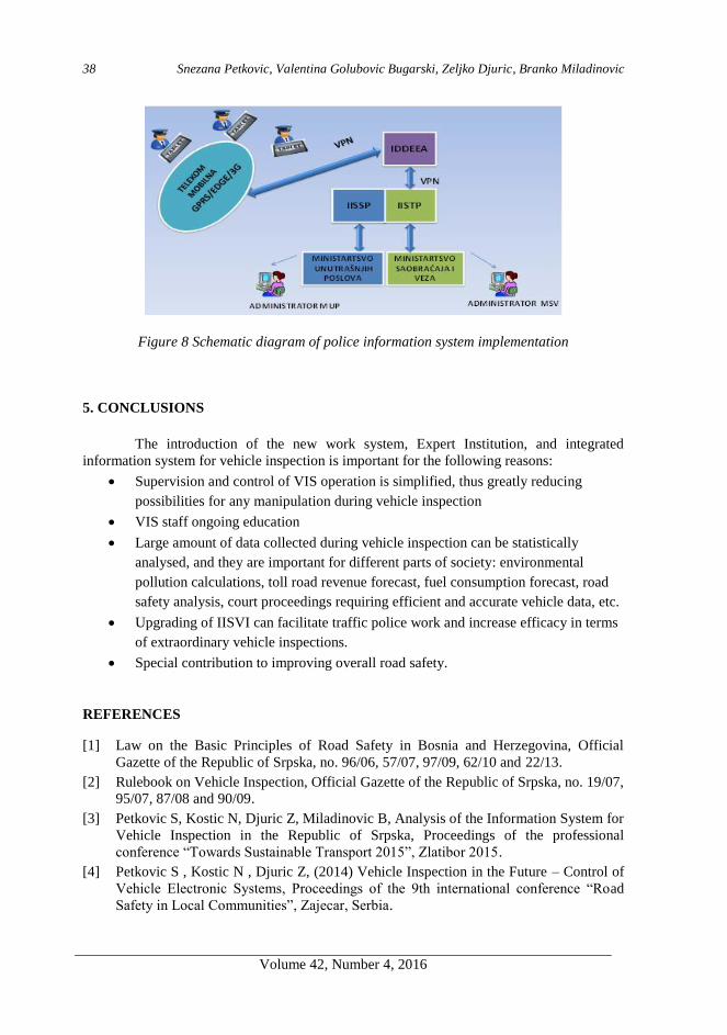
Figure 8 shows an option for the implementation of the integrated information
system for the police (IISP).
Snezana Petkovic, Valentina Golubovic Bugarski, Zeljko Djuric, Branko Miladinovic
Volume 42, Number 4, 2016
38
Figure 8 Schematic diagram of police information system implementation
5. CONCLUSIONS
The introduction of the new work system, Expert Institution, and integrated
information system for vehicle inspection is important for the following reasons:
Supervision and control of VIS operation is simplified, thus greatly reducing
possibilities for any manipulation during vehicle inspection
VIS staff ongoing education
Large amount of data collected during vehicle inspection can be statistically
analysed, and they are important for different parts of society: environmental
pollution calculations, toll road revenue forecast, fuel consumption forecast, road
safety analysis, court proceedings requiring efficient and accurate vehicle data, etc.
Upgrading of IISVI can facilitate traffic police work and increase efficacy in terms
of extraordinary vehicle inspections.
Special contribution to improving overall road safety.
REFERENCES
[1] Law on the Basic Principles of Road Safety in Bosnia and Herzegovina, Official
Gazette of the Republic of Srpska, no. 96/06, 57/07, 97/09, 62/10 and 22/13.
[2] Rulebook on Vehicle Inspection, Official Gazette of the Republic of Srpska, no. 19/07,
95/07, 87/08 and 90/09.
[3] Petkovic S, Kostic N, Djuric Z, Miladinovic B, Analysis of the Information System for
Vehicle Inspection in the Republic of Srpska, Proceedings of the professional
conference “Towards Sustainable Transport 2015”, Zlatibor 2015.
[4] Petkovic S , Kostic N , Djuric Z, (2014) Vehicle Inspection in the Future – Control of
Vehicle Electronic Systems, Proceedings of the 9th international conference “Road
Safety in Local Communities”, Zajecar, Serbia.

Improvement of vehicle inspection technology by introducing integrated information system
Volume 42, Number 4, 2016
39
[5] Radic R, Stupar S, (2015), Calculation of CO2 Emissions From Road Vehicles,
Proceedings of the professional conference “Vehicle Inspections in the Republic of
Srpska 2015”, University of Banja Luka, Banja Luka, pages 39-50.
[6] Miladinovic B, (2013) Odometer Mileage Report, Bulletin, Year IV, Number 7,
University of Banja Luka, pages 38-48.
[7] Miladinovic B, Barudzija G, (2012), Road Safety in the Republic of Srpska and
Traffic Police Efficiency, Bulletin, Year III, Number 5, University of Banja Luka,
pages 25-31.
[8] Internal instructions, presentations, reports, Vehicle Inspection Expert Institution of
the Republic of Srpska.

Intentionally blank

Volume 42, Number 4, 2016
COMPARATIVE COMPOSITE AND CONVENTIONAL DRIVE SHAFT
ANALYSIS
Marko Denić1, Zorica Đorđević, Vesna Marjanović, Nenad Petrović, Nenad Kostić
UDC:621.824
ABSTRACT: Composite materials are still not in widespread use in the industry due to
their unexplored potential. One of the uses of composite materials can be in drive shafts.
Using lightweight materials for propulsion components can potentially significantly
decrease their weight in comparison to their metal counterparts, while maintaining
performance characteristics. Drive shafts are subjected to torsion and in rare cases they are
subjected to bending. This paper explores the angle of twist in case of torsion, deflection in
case of bending, mass, and eigenfrequencies (1st mode) in three cases of frequently used
composites (E Glass, High Strength Carbon, and Kevlar-49), and compares the results to
those of conventional material shafts. Numerical testing of examples was conducted in
Autodesk Helius Composites 2016. The research also covers possible variations of
composite shafts to include the influence of the number of layers in the composite, their
directions, and possible combination of composite and metal in shaft design and their
respective influences on shaft characteristics.
KEY WORDS: composite materials, drive shaft, shaft torsion, bending, eigenfrequency
KOMPARATIVNA ANALIZA KOMPOZITNOG I KONVENCIONALNOG
KARDANSKOG VRATILA
REZIME: Kompozitni materijali nisu još uvek u širokoj primeni u industriji zbog njihovog
neistraženog potencijala. Jedna od primena se može naći u kardanskim vratilima. Upotreba
lakih materijala za pogonske elemente može značajno smanjiti njihovu masu u poređenju sa
istovetnim čeličnim elementima, zadržavajući, pri tom, iste performanse. Kardanska vratila
opterećena su na uvijanje i u ređim slučajevima na savijanje. Rad istražuje ugao uvijanja u
slučaju torzije, ugib u slučaju savijanja, masu i sopstvene frekvencije za tri najčešće
upotrebljena kompozitna materijala (staklena vlakna, ugljenična vlakna visoke čvrstoće,
kevlar) i predstavlja poređenje rezultata dobijenih ispitvanjem konvencionalnih kardanskih
vratila. Numerička analiza primera vršena je u Autodesk Helius Composites 2016.
Istraživanje, takođe, pokriva potencijalne varijacije kompozitnih materijla uključujući uticaj
broja slojeva kompozitnih materijala, orijentacije vlakana u slojevima, i moguće
kombinacije kompozitnih i metalnih metarijala kardanskih vratila, kao i njihov respektivni
uticaj na karakteristike vratila.
KLJUČNE REČI: kompozitni materijali, kardansko vratilo, uvijanje vratila, savijanje,
sopstvene frekvencije
1 Received: July 2016, Accepted September 2016, Available on line December 2016

Volume 42, Number 4, 2016
COMPARATIVE COMPOSITE AND CONVENTIONAL DRIVE SHAFT
ANALYSIS
Marko Denić 1, Zorica Đorđević
2, Vesna Marjanović
3, Nenad Petrović
4, Nenad Kostić
5
UDC:621,824
1. INTRODUCTION
The automobile industry has seen a growth in implementation of composite
materials in the past years, however it is still a slow process, as the material properties for
various load cases is still being researched. Following this trend of using lightweight
materials to replace steel components more and more parts are being produced using
composites. However composites are still most frequently found in static and cosmetic
elements. Drive shafts made of composites have most recently been featured in some BMW
M series models. Use of composite materials for propulsion components is still a developing
field of study. Drive shafts (cardan shafts) are main driving components for transferring
torque in vehicles. The use of composite materials for making drive shafts implies
decreasing the mass compared to conventional material shafts. In the use of composite
materials the orientation of fibers plays an important role in load distribution and stress
characteristics. Depending on the load case, fibers need to be placed at optimal angles to
minimize deformation of the shaft. The base of this research is to analyze and compare drive
shaft numerical calculations for steel and composite drive shafts in the same loading
scenarios.
Kaviprakash et al. [3] conducted research on fiber orientation in laminar
composites, as well as the order of layering. Their optimization was done in ANSYS for
hybrid shafts made from high strength carbon fibers, high module carbon fibers, Kevlar, and
epoxy resins. The results were compared to conventional shafts and showed improvements
in decreasing mass of approximately 79%, lowering stress as well as improving fuel
economy. Hatwar and Dalu [2] analyzed E Glass and carbon fiber shafts in combination
with epoxy resins. Static analyses conducted in ANSYS were compared to analytical results
for maximum shear strain, shear stress, equivalent stress, natural frequency, and mass, for
steel shafts, carbon, and glass shafts. The results showed a decrease of mass by over 72% for
composite shafts with similar deformation and stress characteristics. Rothe and Bombatkar
[5] tested a composite shaft made from high strength carbon fibers using static, modal, and
buckling analyses. Bhajantri et al. [1] replaced a two-part steel shaft for a single-part
composite shaft decreasing the mass by up to 50% and concluding optimal parameters for
the orientation of fibers in layering using regression analyses. Ravi [4] analyzed composite
1 Marko Denić, Ph. D. student, University of Kragujevac, Faculty of Engineering, Sestre Janjić 6,
34000 Kragujevac, [email protected] 2 Zorica Đorđević, Prof., University of Kragujevac, Faculty of Engineering, Sestre Janjić 6, 34000
Kragujevac, [email protected] 3Vesna Marjanović, Prof., University of Kragujevac, Faculty of Engineering, Sestre Janjić 6, 34000
Kragujevac, [email protected]
4 Nenad Petrović, Assist., University of Kragujevac, Faculty of Engineering, Sestre Janjić 6, 34000
Kragujevac, [email protected] 5 Nenad Kostić, Research assoc., University of Kragujevac, Faculty of Engineering, Sestre Janjić 6,
34000 Kragujevac, nkostić@kg.ac.rs

Marko Denić, Zorica Đorđević, Vesna Marjanović, Nenad Petrović, Nenad Kostić
Volume 42, Number 4, 2016
44
shafts made from carbon fibers using a combination of tetrahedral and hexagonal finite
elements. The results were compared to conventional shafts and showed a decrease in mass
by 24%. The analysis covered hollow and full shafts concluding favourable dimension ratios
for hollow shafts. Sivakandhan and Prabhu [6] optimized fiber angles in symmetrical layers
of equal thicknesses for composite shafts. They optimized composite drive shafts achieving
decreases in mass of 15% and 72% respectively compared to conventional shafts.
This paper analyses single-part laminar composite drive shafts, for possible use in
heavy duty trucks, and gives a comparison of numerical calculations for both the composite
shaft and its steel and aluminium counterparts. Three of the most frequently used composite
materials are used in this research, as determined by literature review. Results are shown for
all parameters for both composite and metal shafts. Analysed properties are twist angle,
deflection, eigenfrequencies, and mass. Additionally variations of the number of layers, their
direction and possible combination with conventional materials are also explored.
Test example drive shafts were tested in Autodesk Helius Composites 2016. This
new software is easy to use and it is accurate in simple load cases in comparison to other
software, which use FEA method, such as ANSYS, Abaqus, and DS CATIA.
2. SELECTION OF MATERIALS
The comparative analyses conducted in this paper aim to show the difference in
performance and mass of conventional, metal, shafts and various frequently used composite
shafts. Calculations were performed in ANSYS and verified in Helius Composites for both
metal and composite shafts.
The conventional materials used for the purposes of this research are S275JR, as it
has widespread use in the automobile industry, and 6061-T6 Aluminium. Material
characteristics are taken from the standard material library in ANSYS and are given in table
1. A survey of available literature on the subject shows that the most frequently used
composite materials for drive shafts are E Glass Epoxy, High Strength Carbon, and Kevlar
(Kevlar-49). Material characteristics for E Glass and Kevlar-49 are taken from the material
library in Helius Composite and are given in table 1. HSC characteristics were used from [3]
and a material with those properties was created in the software manually.
Table 1 Characteristic of steel, aluminum and composite materials
Material E11,
[MPa]
E22,
[MPa]
E33,
[MPa]
G12,
[MPa]
G13,
[MPa]
G23,
[MPa]
12,
[/]
13,
[/]
23,
[/]
,
[kg/
m3]
Steel 2.1∙
105
2.1∙
105
2.1∙
105
8∙
104
7.6∙
104
7.6∙
104 0.3 0.3 0.3 7860
Alumi-
num
6.83∙
104
6.83∙
104
6.83∙
104
2.62∙
104
2.62∙
104
2.62∙
104 0.33 0.33 0.33 2710
E Glass 4.48∙
104
1.24∙
104
1.24∙
104
5.52∙
103
5.52∙
103
3.60∙
103 0.28 0.28 0.36 2080
HSC 1.35∙
105
7∙
103
9.26∙
103
5.8∙
103
6.15∙
103
3.08∙
103 0.31 0.31 0.50 1580
Kevlar-
49
7.58∙
104
5.52∙
103
5.52∙
103
2.07∙
103
2.07∙
103
1.54∙
103 0.34 0.34 0.47 1380

Comparative composite and conventional drive shaft analysis
Volume 42, Number 4, 2016
45
3. EXPERIMENT
Literature suggests general dimensions of shafts in the automobile industry as well
as their loads. This research will be conducted on a modified version of the example from
[2]. The hallow drive shaft is 1000 mm long, 100 mm in diameter, while the wall thickness
is 3.32 mm. The shaft is loaded with 3000 Nm of torque on one end, while the other end is
fixed. In order to analyze bending of the shaft (deflection) the standard procedure for
simulating bending loads was used in three points with a force of 1000 N.
The steel drive shaft was first calculated for maximal shear stresses, twist angle and
deflection of the shaft on bending analytically. In order to verify the analytical method, a
numerical analysis was conducted under the same loading and constraint conditions in
ANSYS. The finite element mesh consists of 15876 tetrahedral elements with 5 mm sides
and 108415 nodes. Calculated values as well as the mass of the steel shaft are given in table
2.
Table 2 Analytical and Numerical results comparison for steel shaft
Analytical Numerical Difference [%]
Shear Stress [MPa] 63.58 63.917 0.527
Twist angle [ ] 0.911 0.947 3.801
Deflection [mm] 0.076 0.084 9.524
Mass [kg] 7.916 7.916 0
Comparing the calculated values, it can be concluded that the differences in results
are less than 10%, and given the magnitude of the values, the numerical results are adopted
as valid.
Further calculations of the composite and aluminium shafts, conducted in Autodesk
Helius Composites 2016, will be compared to the numerical results from ANSYS for the
steel shaft.

Marko Denić, Zorica Đorđević, Vesna Marjanović, Nenad Petrović, Nenad Kostić
Volume 42, Number 4, 2016
46
4. RESULTS
Numerical calculation resaults are shown and compared graphically to best
illustrate the difference in characteristics of the examined materials of shafts. Results
attained are mass, twist angle, deflection, and eigenfrequency values for steel, aluminum, E
Glass, HSC and Kevlar-49 shafts.
The greatest benefit of using composite shafts in the automobile industry is
decreasing the mass of the vehicle. The masses of the examined shafts are given in figure 1.
Figure 1 Masses of drive shafts
The twist angle is the other important parameter calculated for the shafts. Figure 2
shows the twist angle values in degrees for all calculated drive shafts.
Figure 2 Twist angles of drive shafts
Even though drive shafts in automobiles are most frequently just subjected to
torsion, they are also calculated for the case of bending, usually by subjecting them to forces
in three points. The maximal deflection is calculated in the middle of the shaft. There are no
suggestions stipulated for deflection, however it is best to keep deflection under a few
millimetres per meter of length. As the drive shaft has enough clearance to withstand such
deformations due to stochastic changes in terrain over which the vehicle is moving these
small deflections are acceptable. Figure 3 shows maximal deflection values in the middle of
the shaft.

Comparative composite and conventional drive shaft analysis
Volume 42, Number 4, 2016
47
Figure 3 Deflection of drive shafts
Figure 4 graphically shows values of eigenfrequencies (for the 1st mod) for each
shaft. One of the main reason for practical implementation of two-part steel drive shafts is
that the single-part drive shaft exhibited unfavourable eigenfrequencies due to the length of
the shaft. Due to a drastic difference in eigenfrequencies of composite material shafts, two-
part metal shafts can be exchanged for single-part composite shafts.
Figure 4 Eigenfrequencies of drive shafts (1st mode)
All fibers for the calcul ompo n n l o 45 n o l
as suggested by literature as being optimal positioning of fibers in the layers of the
composite for more than one loading scenarios.
5. COMPOSITE VARIATIONS
Further analysis is directed towards determining the best variation of the composite
drive shafts. The variation of the number of layers by doubling the number in every
sequential iteration is conducted to determine the influence of the change in the number of
layers on the previously calculated parameters. The overall thickness of the layers is 3.32
mm and is constant. All the same calculations were conducted as in the previous section,
except that the experiment of the change in the number of layers is only conducted on the E
Glass shaft, as it is most frequently used in literature. The results of the varied number of
layers are shown in table 3.

Marko Denić, Zorica Đorđević, Vesna Marjanović, Nenad Petrović, Nenad Kostić
Volume 42, Number 4, 2016
48
Table 3 Influence of the change in the number of layers on deflection, torsion and
eigenfrequency for E Glass drive shafts
Number of layers 4 8 16 32
Deflection [mm] 1.0872 1.0739 0.0708 1.07
Angle of Twist [⁰] 6.039 5.759 5.693 5.676
Eigenfrequency(1st mode)
[Hz] 341.082 341.191 343.694 343.819
As the change in the number of layers has been found to not have a big influence
on shaft characteristics, the next variation in this experiment is directed towards determining
the influence of the layer order. Various orientation of the angle of fibers when the fibers in
the layers are oriented from 0⁰ to 90⁰ is tested for the four layer E Glass shaft. Two
variations are tested with layer combinations of -45⁰, 0⁰, 45⁰, and 90⁰ in variations and the
resulting characteristics presented in table 4, with the first combination being the same as in
the first comparison.
Table 4 Influence of fiber direction changes in layers
Directions of fibers combinations in
layers
45⁰/-45⁰/45⁰/-45⁰
0⁰/-45⁰/45⁰/90⁰
45⁰/0⁰/90⁰/-45⁰
Deflection [mm] 1.0872 0.926 0.822
Angle of Twist [⁰] 6.039 8.152 9.873
Vibration (1st mode) [Hz] 341.082 369.584 392.366
Due to the high costs of composite materials, there is a tendency to combine
conventional with composite materials in drive shaft design to form hybrid drive shafts. This
way the best of both materials characteristics can be exploited. The idea is to start off with a
steel or aluminium base and layer over them with composites. The distribution of stress in
the layers needs to be accounted for in order to avoid having the metal base from
transmitting the greater part of the load, thereby not using the potential of the composite
layers. This research tested steel and aluminium base shafts in combination with E Glass
composite in four layers 1.66 mm thick oriented in the setup of 45/-45/45/-45. The steel and
aluminium bases have thicknesses of 1.66 in both cases. Table 5 gives the characteristics of
two hybrid shafts and compares the values to their base metal and purely E Glass shafts.

Comparative composite and conventional drive shaft analysis
Volume 42, Number 4, 2016
49
Table 5 Comparison of hybrid steel/E Glass and Aluminum/E Glass shaft to the metal and E
Glass composite drive shaft characteristics
Material Steel/
E Glass Steel
Aluminum
/E Glass Aluminum E Glass
Deflection [mm] 0.342 0.088 0.577 0.259 1.087
Angle of Twist [⁰] 2.594 0.947 4.11 2.699 6.358
Mass [kg] 5.01 7.916 2.414 2.723 2.093
Eigenfrequency
(1st mode) [Hz]
393.018 614.941 436.039 611.642 341.082
6. CONCLUSIONS
This paper analysed the use of composite materials and their variations and
compared their characteristics (deflection, torsion, eigenfrequency and mass) with those of
conventional shafts.
The use of composite materials for creating drive shafts can significantly decrease
the mass of this component. The difference in weight among the composite shafts is around
10%, and the composite with the smallest mass is Kevlar-49 with a decrease in mass of
82.36%. Other tested characteristics for composite shafts do not show such drastic
differences.
High strength carbon (HSC) showed itself as the least susceptible to torsion, with a
twist angle of 2.485⁰, which is less than that of its aluminium counterpart, but over 2.6 times
greater than that of the corresponding steel shaft. E Glass has performed the worst under
these circumstances with a twist angle of 6.358⁰ which is still acceptable.
Deflection has the greatest variance in results between the materials. Of the
composite shafts HSC performed the best, while Kevlar-49 had the greatest deflection,
however all deflection values can be considered acceptable due to their minuscule values.
Eigenfrequencies are significantly lower for composite materials than for conventional steel
and aluminum shafts, as was expected.
Further variations of the E Glass composite by changing the number of layers made
small decreases the twist angle with the increase of the number of layers, and had an overall
insignificant influence on the characteristics of the shaft in comparison to the increased
complexity of production. The changes in fiber orientation in the layers only slightly
improved deflection from the initial setup, while worsening other characteristics. Therefore
it can be concluded that the initially calculated setup of composites with 4 layers with angles
of fibers changing from +45⁰ to -45⁰ in each layer to be optimal.
Due to the costliness of composite materials a compromise in the design solution
can give favourable results compared to conventional design solutions. The combination of
E Glass with steel, and E Glass with aluminium was tested and demonstrated improvements
in deflection (around 31% increase for Glass/steel), and twist angle (around 40% decrease
for E Glass/steel), while having a greater mass and eigenfrequency compared to a purely E

Marko Denić, Zorica Đorđević, Vesna Marjanović, Nenad Petrović, Nenad Kostić
Volume 42, Number 4, 2016
50
Glass composite shaft, but a significantly lower mass than their corresponding metal
counterparts.
Any decrease of mass in automobiles is in direct correlation with the decrease of
fuel consumption. An improvement of fuel economy through further research into, and
implementation of composite materials inevitably leads to a decrease of automobiles
negative effects on the environment.
REFERENCES
[1] B j n S. V., B j n C. S., S n olk M. A., Am pu S. S., „D n n
An l o Compo D v S “, In n on l Jou n l o En n n R &
Technology (IJERT), ISSN:2321-7308, Vol. 3 Special Issue 3, May 2014.
[2] H w K. P., D lu S. R., „D n n An l o Compo D v S “,
International Journal of Science and Research (IJSR), ISSN (Online):2319-7064, Vol.
4 Issue 4, April 2015.
[3] Kaviprakash G., Lawrence I. D., Kannan C. R., Regan A. P., „D n n An l o
Compo D v S o Au omo v Appl on“, In n on l Jou n l o
Engineering Research & Technology (IJERT), ISSN:2278-0181, Vol. 3 Issue 11,
November 2014.
[4] R v A., „D n, Comp on n An l o Compo D v Shaft for an
Au omob l “, In n on l R v w o Appl En n n R , ISSN:2248-
9967, Vol. 4, Number 1 (2014), pp. 21-28.
[5] Ro G. C., Bomb k S. A., „D n n An l o Compo M l D v
S “, In n on l Jou n l o Inov v nd Emerging Research in Engingeering
(IJERT), ISSN:2394-5494, Vol. 2 Special Issue 1, 2015.
[6] S v k n n C., P b u P. S., „Op mum D n n An l o D v S n
Compo M l“, M l S n R In , Vol. 8(2), 125-130 (2011).

Volume 42, Number 4, 2016
DETERMINATION THE NORMS OF FUEL CONSUMPTION FOR BUSES
IN THE PUBLIC TRANSPORTATION IN REAL CONDITIONS OF
EXPLOITATION
Slobodan Mišanović1
UDC:629.341
ABSTRACT: Determination the norms of fuel consumption for the buses are operating in
the public transportation system is an important indicator of exploitation, which should
serve as a benchmark when analysing fuel economy of bus. Viewed from a strategic point of
business, optimization of fuel consumption is a significant step in the program of measures
relating to reducing the financial expenses of the company. Lower consumption of fuel
means better environmental performance for vehicles that are manifested through lower
emissions as an important issue in terms of environmental protection and sustainable
development.
In this paper presents an example of determining the norms of fuel consumption for the
largest group of articulated buses ‘'Solaris Urbino 18'', which are in fleet JKP GSP
''Beograd'' (City Public Transport Company “Belgrade“).
The norms were obtained by statistical analysis of the representative sample lines where the
buses in operation. Norms of consumption was obtained on the basis of interval estimates of
the mean value fuel consumption for selected lines and establishing a correlation
dependence of the fuel consumption and exploitation speed of bus.
KEY WORDS: norms of fuel consumption, bus, public transportation
ODREDJIVANJE NORMATIVA POTROŠNJE GORIVA ZA AUTOBUSE U
JAVNOM GRADSKOM PREVOZU U REALNIM USLOVIMA EKSPLOATACIJE
REZIME: Odredjivanje normativa potrošnje pogonskog goriva kod autobusa koji se koriste
u sistemu javnog gradskog prevoza je važan eksploatacioni pokazatelj, koji je posbno
značajan za analizu gorivne ekonomičnosti autobusa. Gledano sa strateške tačke
poslovanja, optimizacija potrošnje goriva predstavlja značajan korak u programu mera koje
se odnose na smanjenje finansijskih troškova preduzeća. Manja potrošnja goriva daje bolje
ekološke performanse vozila odnosno niži nivo emisije štetnih gasova što doprinosi zaštiti
životne sredine. U ovom radu predstavljen je primer utvrđivanja normativa potrošnje
goriva za grupu zglobnih autobusa '' Solaris Urbino 18 '', koji su u voznom parku JKP GSP
''Beograd ''. Normativi su dobijeni statističkom analizom na reprezentativnom uzorku na
linijama gde su autobusi u radu, korišćenjem intervalne ocene srednje vrednosti potrošnje
goriva za odabrane linije i uspostavljanjem korelacione zavisnosti eksploatacione brzine
kretanja i potrošnje goriva autobusa.
KLJUČNE REČI: normativ potrošnje goriva, autobus, javni prevoz
1 Received: July 2016, Accepted September 2016, Available on line December 2016

Volume 42, Number 4, 2016
DETERMINATION THE NORMS OF FUEL CONSUMPTION FOR BUSES
IN THE PUBLIC TRANSPORTATION IN REAL CONDITIONS OF
EXPLOITATION
Slobodan Mišanović1
UDC:629.341
1. INTRODUCTION
Determination of norms of fuel consumption for different groups of buses that
make up the fleet of one company for public transport, stems from the fact of their different
tehnical characteristics and different service conditions on the routes where vehicles operate.
In this paper is present a case of determining norms of fuel consumption for a
group of articulated buses ’’Solaris Urbino 18’’. The fleet GSP ’’Beograd’’ has 200 buses of
this type that were acquired in the period August-December 2013. Of the planned number of
640 buses in operation on work days, this group accounts for about 31% of the vehicles in
operation and represents the largest group of buses. At the time when norms determination,
vehicles have passed the phase of elaboration of the vehices and their technical condition
was optimal. Mileage of tested vehicles is ranged from of 60 000 and 90 000 km.
When were buses purchased an integral part of the documentation of the tender
was the test fuel consumption according to the method SORT 1 (urban cycle). The
manufacturer has declared consumption for this test of 56 L / 100km. The question is how
this result is close to the actual fuel consumption in the real system. In Figure 1 is presented
one of the buses from that group with the basic technical characteristics
SOLARIS Urbino 18 Engine: DAF PR 228 Euro 5 Power: 231 KW Torque 1275 Nm Volume: 9,186 cm
3 Transmission: ZF-6AP Length: 18.000 mm Width: 2,550 mm Height: 3,050 mm Vehicle capacity: 159 passengeres Year: 2013 Number of vehicles in fleet: 200
Figure 1 Articulated bus Solaris Urbino 18 with basic technical data
1 Slobodan Mišanović, Project manager, City Public Transport Company “Belgrade“, 29 Kneginje
Ljubice Str., 11000 Belgrade; Ph. D. student, University of Kragujevac , Faculty of Engineering, 6
Sestre Janjić Str., 34000 Kragujevac, Serbia, [email protected]

Slobodan Mišanović
Volume 42, Number 4, 2016
54
2. THE INFLUENTIAL FACTORS ON THE FUEL CONSUMPTION OF BUSES
FOR URBAN TRANSPORT
The fuel consumption of buses is a complex function of several independent
factors. The most important factors to fuel consumption are:
• Performance vehicles (powertrain features-power, torque, specific consumption,
transmission characteristics, weight, aerodynamics)
• Characteristics of road (longitudinal gradients, horizontal curve, adhesion
characteristics of road)
• Traffic conditions ( traffic flow, number of passengers in bus , keeping at the traffic
lights, the number of stations, etc.)
• Period of exploitation (winter, summer - the use of air conditioners)
• Technique vehicle handling.
Fuel consumption of buses for public transport in terms of the characteristics in
direct connection with the constructive and exploitation characteristics of the engine, the
load of the bus, the size of the resistance movement, the characteristics of transmission of
the remaining components.
The density and structure of traffic flow, the level of regulation of intersections and
the number of stations on the route of the most important factors when the conditions of the
bus in question. These impacts can best demonstrate the value of exploitation speed (Ve) by
bus realized on the line [1].
Ve = 2Lr· Te-1 [km· h-1
] (1)
Ve = 2Lr · (Tv + Tss + Tts)-1
[km· h-1
] (2)
Ve- exploitation speed [km• h-1
]
Lr - length of route [km]
Te - the duration of use [h]
Tv - driving time [h]
Tss- time spent waiting at stations [h]
Tts - time spent at a traffic standstill [h].
If we take into account the time a vehicle spends in the terminal while waiting for
the departure (Tt - time spent at the terminus), then we have a turnaround time (To = Tv +
Tss + Tts + Tt) gives a speed turnaround such as:
Vo = 2Lr · To-1
[km· h-1
] (3)
Ve>Vo (4)
From the expressions on the operating speed, we can conclude that as conditions
for the movement tends to a greater number of stations, signal intersections, the frequent
delays in traffic flow to the lower speed. With the decline of the value of exploitation speed
increases fuel consumption which can be show the following picture:

Determination the norms of fuel consumption for buses in the public transportation
in real conditions of exploitation
Volume 42, Number 4, 2016
55
Figure 2 Dependence of fuel consumption and exploitation speed for articulated bus [2]
Figure 3 Influential factors on fuel consumption
From Figure 3 [2] it can be concluded that the exploitation speed of movement of
buses for public transport in direct dependence on the influencing factors while fuel
consumption in inverse proportion with the exploitation speed as already presented in
Figure 2. For this reason, the greatest number of empirical models of fuel consumption
(Akcelik-Richardson model, CNR-model, Gattuso model) as a base the size of the benefit
precisely the exploitation speed of the bus [3].

Slobodan Mišanović
Volume 42, Number 4, 2016
56
3. METHODOLOGY OF DETERMINING FUEL CONSUMPTION FOR BUSES
SOLARIS URBINO 18
Determining norms of consumption of fuel for vehicle group ''Solaris Urbino 18'',
are done on the basis of the results obtained :
• The statistical method based on the measurement of fuel consumption in real
conditions of exploitation by buses and lines [4]
• The research covered the period from 1.3-15.4.2014 and 1.10-31.10.2014.year,
given that months: March, April and October are the authoritative period of
analysis from the aspect of intensity of passenger flows, traffic conditions and
external temperature as the most influential factors affecting fuel consumption in
general
• The results obtained on the fuel consumption at the level of the working day, on
selected lines for each bus separately. Everyday was measured quantity of fuel
through the electronic system to refuel, for each bus separately. Daily mileage is
obtained on the basis of reading from tachograph
• Results of the daily consumption of fuel that had extremely high values as a result
of disruptions in traffic or discrepancies in the records of refueling were not taken
into analysis.
It is known that the fuel consumption of motor vehicles as a stochastic
phenomenon is subject to the law of normal (Gaussian) distribution. This law allows the use
of statistical methods, it possible for every type of vehicles are given estimate the expected
fuel consumption.
Based on a representative sample (Xi, i = 1, n) performed a statistical analysis of
the results of the fuel consumption of buses Solaris Urbino 18 on lines using the mean value
(Xs) and standard deviation (s).
(5)
√∑
(6)
The norm of fuel consumption was obtained on the basis of interval estimates of
the mean fuel consumption (µ) of the basic set with a probability of 95%, using a normal
distribution for the sample n≥ 30th [5].
(
√
√ )
(7)
4. EXAMPLE OF MEASURING AND NORMS FUEL CONSUMPTION ON THE
LINE NO.17
Line No.17 (Konjarnik-Zemun), according to the spatial position is the tangential
line, of medium length (Lr) of 16.1 km. (Figure 5). Average exploitation speed (Ve ) is 18.5
km h-1. The number of stations in the direction '' A '' is 27, in the direction of ''B'' is 30.

Determination the norms of fuel consumption for buses in the public transportation
in real conditions of exploitation
Volume 42, Number 4, 2016
57
Average distance between stations is 575 meters. Line in terms of the number of passengers
is one of the highly loaded lines [7].
Figure 4 High characteristics of the rute line no. 17 Konjarnik-Zemun
Figure 5 Spatial position and altitude characteristics of the route line No.17
In table 1. presents the results of measurement of fuel consumption on city line
No.17 (Konjarnik-Zemun) for 5 buses SOLARIS Urbino18 (Garage Number:
3002,3003,3016,3017,3018) during October 2014 [4].

Slobodan Mišanović
Volume 42, Number 4, 2016
58
Table 1 Results of measurement of fuel consumption on the line 17 (October 2014)
Number
of
Consum
ption
Number
of
Consum
ption
Number
of
Consum
ption
Number
of
Consum
ption
measure
ment
[L/100
km] measure
ment
[L/100
km] measure
ment
[L/100
km] measure
ment
[L/100
km]
1 44.03 21 52.33 41 53.6 61 54.92
2 46.31 22 52.36 42 53.63 62 55.02
3 47.57 23 52.46 43 53.63 63 55.07
4 48.56 24 52.54 44 53.69 64 55.2
5 48.98 25 52.54 45 53.69 65 55.2
6 49.18 26 52.6 46 53.82 66 55.25
7 49.23 27 52.65 47 53.82 67 55.33
8 49.24 28 52.67 48 53.85 68 55.42
9 49.38 29 52.8 49 53.9 69 55.76
10 49.74 30 52.83 50 54.05 70 55.88
11 50.00 31 52.88 51 54.24 71 56.45
12 50.41 32 52.88 52 54.43 72 56.5
13 50.71 33 52.91 53 54.44 73 58.31
14 51.08 34 52.94 54 54.51 74 58.47
15 51.44 35 53.04 55 54.51 75 60.48
16 51.53 36 53.05 56 54.57 76 60.82
17 51.6 37 53.28 57 54.58 77 61.45
18 51.86 38 53.28 58 54.62 78 62.25
19 51.87 39 53.28 59 54.64
20 52.22 40 53.36 60 54.92
Processing of a statistical sample of 78 measurements, obtained the arithmetic
average (Xs) 53.36 L / 100 km and standard deviation (s) 3.06 L/100 km.
To verify that the distribution of the test sample is consistent with ''Normal''(Gauss)
distribution, we will distribute samples of fuel consumption in the class, as presented at the
figure 5.

Determination the norms of fuel consumption for buses in the public transportation
in real conditions of exploitation
Volume 42, Number 4, 2016
59
Figure 6 Distribution of fuel consumption samples in the class for Solaris Urbino 18 buses
on the line No.17
Using a statistical test '' 2 '' (Chi-square test) of the verify accordance the
theoretical with empirical distribution of the sample (Figure 7).
Figure 7 Empirical and theoretical 2 distribution sample of fuel consumption on the line
No.17
2 0,05 = 4.929 (8)
respectively 2 0,05 = 4.929 < 7.815 (9)

Slobodan Mišanović
Volume 42, Number 4, 2016
60
where 7,815 table value 2 0,05, k = r-m-1 = 3 degrees of freedom (r = number of
classes 6, m = 2 number degrees of freedom for ’’normal’’ distribution). Given that the
resulting value 2 0,05 less than the value of the table , has demonstrated compliance with the
’’normal’’ distribution.
Based on the results of measuring the arithmetic value (Xs), standard deviation (s),
normative consumption was obtained on the basis of interval estimates of the mean basic set
with a probability of 95%, using a normal distribution for the sample n≥ 30 [5].
(
√
√ )
(10)
In the present case of P (52.69 <μ <54.05) = 0.95, with a probability of 0,95, we
can argue that on the city's line N0.17 for buses Solaris Urbino 18, the average consumption
of fuel in the range of 52.69 to 54.05 L/100 km, which is the norm of consumption using the
above methodology can be reached the relevant norms of consumption of fuel for other
lines where buses SOLARIS Urbino18 are worked. The following figures are examples of
the empirical distribution of fuel consumption on the lines No.23;75;83.
Figure 8 The empirical distribution of fuel consumption for Solaris Urbino 18, on the line
no.23

Determination the norms of fuel consumption for buses in the public transportation
in real conditions of exploitation
Volume 42, Number 4, 2016
61
Figure 9 The empirical distribution of fuel consumption for Solaris Urbino 18, on the line
no.75
Figure 10 The empirical distribution of fuel consumption for Solaris Urbino 18, on the line
no.83
In Table No. 2 presents norms of fuel consumption for buses SOLARIS Urbino
18, on city lines, are included in the research (October 2014).

Slobodan Mišanović
Volume 42, Number 4, 2016
62
Table 2 Norms of fuel consumption for buses SOLARIS Urbino 18
No.line
Exploitation
speed
Average
consumption
[Xs]
Stan.deviation
[s]
Sample
size
Norms of fuel
consumption
[Km h-1
] [L/100 km] [L/100 km]
[L/100 Km]
’’from ’’ ’’to’’
16 15.6 59.18 4.09 88 58.33 60.04
17 18.5 53.36 3.06 78 52.69 54.05
18 20.4 54.37 3.76 81 53.55 55.19
23 17.1 59.57 4.07 140 58.90 60.25
27 15.1 59.94 1.93 57 59.44 60.45
27E 16.3 58.80 2.82 51 58.06 59.61
31 13.8 62.43 4.78 84 61.41 63.46
37 16.3 56.01 2.72 76 55.40 56.62
43 16.7 51.30 2.81 72 50.02 52.57
51 15.8 52.86 1.99 77 52.41 53.30
52 16.8 56.34 2.99 46 55.47 57.20
53 18.1 56.32 2.57 31 55.42 57.23
56 19.6 52.88 2.55 32 51.99 53.77
58 17.3 51.98 3.39 35 50.86 53.10
59 18.4 60.71 2.63 52 59.99 61.43
65 16.1 56.31 3.19 63 55.53 57.10
68 17.8 54.66 3.29 42 53.67 55.66
71 16.3 53.21 1.75 43 52.68 53.73
72 23 51.75 3.20 42 50.79 52.72
75 17.3 56.37 3.01 50 55.54 57.21
77 14.9 55.52 2.94 67 54.81 56.22
83 15 60.50 3.60 46 59.46 61.54
85 18.2 52.48 1.57 30 51.92 53.05
88 20.6 52.00 3.05 44 51.10 52.90
89 17.8 53.23 3.65 51 52.23 54.24
95 19.4 53.29 3.72 102 52.57 54.02
96 19.1 51.79 3.17 31 50.68 52.91
101 28.1 44.63 3.40 38 43.55 45.79
531 26.7 39.16 1.65 34 38.60 39.71

Determination the norms of fuel consumption for buses in the public transportation
in real conditions of exploitation
Volume 42, Number 4, 2016
63
Based on the study, results are presented in the table no.2, we can give a
correlative relationship between the average fuel consumption and exploitation speed
(Figure 11) for some characteristic lines: urban-diametrical (No:31;83;16), urban-radial
(No:52;75); urban-tangential (No:17;88) and one suburban line (No.101).
Figure 11 Correlation dependence of fuel consumption and exploitation speed for SOLARIS
Urbino 18
Since that the correlation coefficient R2 = 0.971, extremely high, it indicates an
extremely strong the linear relationship between fuel consumption and exploitation speed. If
in linear regression equation, change the value of exploitation speeds of 12-30 km h-1
, which
is a realistic range of exploitation speeds and to cover all operating modes: City, combined,
suburban, we can reach results norms of consumption as shown in Table 3.
Table 3 Norms of fuel consumption for a group of vehicles SOLARIS Urbino18, obtained
from the regression
Exploitation speed Expected consumption Norms of fuel consumption [L/100km]
[Km h-1] [L/100km] 'from'' 'to''
12 63.4 62.14 64.66
13 61.58 60.32 62.84
14 60.46 59.2 61.72
15 59.35 58.09 60.61
16 58.23 56.97 59.49
17 57.11 55.85 58.37
18 55.99 54.73 57.25
19 54.87 53.61 56.13
20 53.76 52.5 55.02
21 52.64 51.38 53.9
22 51.52 50.26 52.78

Slobodan Mišanović
Volume 42, Number 4, 2016
64
23 50.4 49.14 51.66
24 49.28 48.02 50.54
25 48.17 46.91 49.43
26 47.05 45.79 48.31
27 45.93 44.67 47.19
28 44.81 43.55 46.07
29 43.69 42.43 44.95
30 42.58 41.32 43.84
If we look at fuel consumption individually for each vehicle SOLARIS Urbino 18,
which is the generated in October 2014 in the regular operation in depot '' Novi Beograd '',
we can conclude the following:
• The average fuel consumption for a group of buses SOLARIS Urbino 18 (a total of
100 buses) is 54.05 L/100 km
• All vehicles operate exclusively on urban or urban-suburban lines and depending
on the exploitation of speed and load, the consumption ranges from 49.4 to 62.3
L/100 km
• The results obtained fuel consumption in real terms in October 2014 and norms of
consumption that are made on the basis of the sample have a high degree of
concurrency
• If the compare values of fuel consumption on the line no.17 which was obtained by
statistical method 53.36 L/100 km, with the results obtained in the test using the
method ’’SORT 1’’, where the resultant consumption of 56 L/100 km [6], we
conclude that it is expected , considering that this is a more difficult driving cycle
that has the operating speed of 12.7 km h-1
, compared to the exploitation speed on
the line No.17 which is 18.5 km h-1
• Fuel consumption during the period when using air conditioning on the bus to be
increased by 15% compared.
5. CONCLUSIONS
Determination of norms of fuel consumption for buses operating in the public
transportation system is an important indicator of exploitation, which should serve as a
benchmark when analysing fuel economy bus. The necessity of defining norms of fuel
consumption for each type of city bus, depending on the line where he works in real
conditions of exploitation gives all the specifics of the given line. Monitoring of fuel
consumption of each bus allows analysis and comparison with the defined standards of
consumption. Savko deviation from norms means taking appropriate technical-
organizational measures to return consumption within prescribed limits.
REFERENCES
[1] Банковић, Р.: “Планирање јавног градског превоза, универзитетски
уџбеник”,1983, Привредни преглед.
[2] ''UITP Project SORT- Standardised On-Road Tests cycles'', (secend
edition),UITP,D/2009/0105/31, 2009, Brussels.

Determination the norms of fuel consumption for buses in the public transportation
in real conditions of exploitation
Volume 42, Number 4, 2016
65
[3] Tramontana, D.: “Energy consumption by BHLS vehicles, Action cost-TU 603- Bus
with high level of service”, 2009, Barcelona.
[4] Mišanović, S.: “Normativi potrošnje pogonskog goriva za autobuse Solaris Urbino
18 u GSP’’Beograd’’, 2014, (interni dokument).
[5] Vukadinović, S.: “Elementi teorije verovatnoće i matematičke statistike”, Privredni
pregled, 1990, Beograd.
[6] ''Reports of Fuel consumption test according to the SORT 2009 procedure for 5 buses
Solaris Urbino 18'' of GSP ’’Beograd’’, Applus IDIADA, Project No.LM1402001,
Santa Oliva (Spain), February-April 2014.
[7] Mišanović, S.: “Istraživanje uticajnih faktora potrošnje goriva kod autobusa za gradski
prevoz sa metodologijom određivanja normativa potrošnje goriva”, seminarski rad na
doktorskim studijama, FIN Kragujevac, 2016.

MVM – International Journal for Vehicle Mechanics, Engines and Transportation Systems
NOTIFICATION TO AUTHORS
The Journal MVM publishes original papers which have not been previously published in
other journals. This is responsibility of the author. The authors agree that the copyright for
their article is transferred to the publisher when the article is accepted for publication.
The language of the Journal is English.
Journal Mobility & Vehicles Mechanics is at the SSCI list.
All submitted manuscripts will be reviewed. Entire correspondence will be performed with
the first-named author.
Authors will be notified of acceptance of their manuscripts, if their manuscripts are adopted.
INSTRUCTIONS TO AUTHORS AS REGARDS THE TECHNICAL ARRANGEMENTS
OF MANUSCRIPTS:
Abstract is a separate Word document, “First author family name_ABSTRACT.doc”. Native
authors should write the abstract in both languages (Serbian and English). The abstracts of
foreign authors will be translated in Serbian.
This document should include the following: 1) author’s name, affiliation and title, the first
named author’s address and e-mail – for correspondence, 2) working title of the paper, 3)
abstract containing no more then 100 words, 4) abstract containing no more than 5 key
words.
The manuscript is the separate file, „First author family name_Paper.doc“ which includes
appendices and figures involved within the text. At the end of the paper, a reference list and
eventual acknowledgements should be given. References to published literature should be
quoted in the text brackets and grouped together at the end of the paper in numerical order.
Paper size: Max 16 pages of B5 format, excluding abstract
Text processor: Microsoft Word
Margins: left/right: mirror margin, inside: 2.5 cm, outside: 2 cm, top: 2.5 cm, bottom: 2 cm
Font: Times New Roman, 10 pt
Paper title: Uppercase, bold, 11 pt
Chapter title: Uppercase, bold, 10 pt
Subchapter title: Lowercase, bold, 10 pt
Table and chart width: max 125 mm
Figure and table title: Figure _ (Table _): Times New Roman, italic 10 pt
Manuscript submission: application should be sent to the following e-mail:
[email protected] ; [email protected]
or posted to address of the Journal:
University of Kragujevac – Faculty of Engineering
International Journal M V M
Sestre Janjić 6, 34000 Kragujevac, Serbia
The Journal editorial board will send to the first-named author a copy of the Journal offprint.

MVM – International Journal for Vehicle Mechanics, Engines and Transportation Systems
OBAVEŠTENJE AUTORIMA
Časopis MVM objavljuje orginalne radove koji nisu prethodno objavljivani u drugim časopisima, što
je odgovornost autora. Za rad koji je prihvaćen za štampu, prava umnožavanja pripadaju izdavaču.
Časopis se izdaje na engleskom jeziku.
Časopis Mobility & Vehicles Mechanics se nalazi na SSCI listi.
Svi prispeli radovi se recenziraju. Sva komunikacija se obavlja sa prvim autorom.
UPUTSTVO AUTORIMA ZA TEHNIČKU PRIPREMU RADOVA
Rezime je poseban Word dokument, “First author family name_ABSTRACT.doc”. Za
domaće autore je dvojezičan (srpski i engleski). Inostranim autorima rezime se prevodi na
srpski jezik. Ovaj dokument treba da sadrži: 1) ime autora, zanimanje i zvanje, adresu prvog
autora preko koje se obavlja sva potrebna korespondencija; 2) naslov rada; 3) kratak
sažetak, do 100 reči, 4) do 5 ključnih reči.
Rad je poseban fajl, „First author family name_Paper.doc“ koji sadrži priloge i slike
uključene u tekst. Na kraju rada nalazi se spisak literature i eventualno zahvalnost.
Numeraciju korišćenih referenci treba navesti u srednjim zagradama i grupisati ih na kraju
rada po rastućem redosledu.
Dužina rada: Najviše 16 stranica B5 formata, ne uključujući rezime
Tekst procesor: Microsoft Word
Margine: levo/desno: mirror margine; unurašnja: 2.5 cm; spoljna: 2 cm, gore: 2.5 cm, dole:
2 cm
Font: Times New Roman, 10 pt
Naslov rada: Velika slova, bold, 11 pt
Naslov poglavlja: Velika slova, bold, 10 pt
Naslov potpoglavlja: Mala slova, bold, 10 pt
Širina tabela,dijagrama: max 125 mm
Nazivi slika, tabela: Figure __ (Table _): Times New Roman, italic 10 pt
Dostavljanje rada elektronski na E-mail: [email protected] ; [email protected]
ili poštom na adresu Časopisa
Redakcija časopisa M V M
Fakultet inženjerskih nauka
Sestre Janjić 6, 34000 Kragujevac, Srbija
Po objavljivanju rada, Redakcija časopisa šalje prvom autoru jedan primerak časopisa.

MVM Editorial Board University of Kragujevac Faculty of Engineering
Sestre Janjić 6, 34000 Kragujevac, Serbia Tel.: +381/34/335990; Fax: + 381/34/333192
www.mvm.fink.rs


![I · MMMMMMMMMMMMMMMMMMMMMMMMMMMMMMMMMMMMMMTFP ! O[A]|VFZL Z__& JØ" o _# AZSFT[ bJF• m m m m m m m m m m m m m m m m m m m m …](https://static.documents.pub/doc/80x56/5e7ba18c1045a43ff17a2374/i-mmmmmmmmmmmmmmmmmmmmmmmmmmmmmmmmmmmmmmtfp-oavfzl-z-j-o-.jpg)


