TECHNICAL GUIDE TOUGH GUN™ ThruArm™ G1 Series Robotic MIG Guns for FANUC® Robots 100iC, 100iC-12, 100iC-6L, 100iC-7L, 120iC, 120iC-10L, 120iC-12L INSTALLATION MAINTENANCE TECHNICAL DATA OPTIONS EXPLODED VIEW & PARTS LIST ORDERING INFORMATION Certified ISO 9001 : 2008 Please read instructions prior to use. Save this manual for future reference
Transcript
TECHNICAL GUIDE
TOUGH GUN™
ThruArm™ G1 Series
Robotic MIG Guns
for FANUC® Robots
100iC, 100iC-12,
100iC-6L, 100iC-7L, 120iC,
120iC-10L, 120iC-12L
INSTALLATION
MAINTENANCE
TECHNICAL DATA
OPTIONS
EXPLODED VIEW & PARTS LIST
ORDERING INFORMATION
Certified ISO 9001 : 2008 Please read instructions prior to use. Save this manual for future reference
6.0 – EXPLODED VIEW AND PARTS LIST ........................................................................................................... 14 7.0 – ORDERING INFORMATION .......................................................................................................................... 14
THANK YOU…
…for selecting a TOUGH GUN™ ThruArm™ G1 Series Robotic MIG Gun. Manufacturing operations demand extremely dependable robotic equipment. With this in mind, the TOUGH GUN
MIG Gun was designed and
engineered to be a reliable tool to support high production within a robotic cell. Your TOUGH GUN MIG Gun is completely assembled and ready to weld, and has undergone numerous quality checks to ensure high performance.
The instructions and illustrations in this technical guide make it easy for you to maintain your TOUGH GUN MIG Gun. Please read, understand, and follow all safety procedures. Keep this Technical Guide booklet as a handy reference when ordering complete guns, parts and special options. For technical support and special applications, please call the Tregaskiss Technical Service Department at 1-855-MIGWELD (644-9353) or fax 1-877-737-2111. Our trained technicians are available Monday through Friday from 8:00 a.m. to 5:00 p.m. EST, and will answer your application or repair questions. Tregaskiss employees build TOUGH GUN Robotic MIG Guns for the world’s welding professionals. We are always striving to improve our products and services, and would appreciate receiving your suggestions or comments. Please contact us immediately if you experience any safety or operating problems.
3
GENERAL SAFETY INFORMATION
Before installation or operation of TOUGH GUN MIG Guns, please read the following safety precautions.
1. Do not touch live electrical parts. The following should be checked to prevent electrical shock:
Faulty or damaged equipment is repaired or replaced.
Equipment is off when not in use.
2. Ensure that all safety devices, guards, shields or barriers are properly in place and connected correctly before allowing operation of the equipment.
3. CSA Standard W117.2 CODE FOR SAFETY IN WELDING AND CUTTING obtainable from the Canadian
ANSI Standard Z49.1 CODE FOR SAFETY IN WELDING AND CUTTING obtainable from the American National Standards Institute, 1430 Broadway, New York, NY 10018.
CALIFORNIA PROPOSITION 65 WARNING This product, when used for welding or cutting, produces fumes or gases which contain chemicals known to the State of California to cause birth defects and, in some cases, cancer. This product contains chemicals, including lead, known to the State of California to cause cancer, and birth defects or other reproductive harm. Wash hands after use.
(California Health & Safety Code Section 25249.5 at seq.)
WARRANTY
Product is warranted to be free from defects in material and workmanship for the period specified below after the sale by an authorized Buyer. Should there be a defect please refer to our Return Merchandise Policy.
PRODUCT WARRANTY PERIOD
TOUGH GUN™ Robotic MIG Guns and Components 180 days
Low-Stress Robotic Unicables (LSR Unicables) 2 years
Tregaskiss reserves the right to repair, replace or refund the purchase price of non-conforming product. Product found not defective will be returned to the Buyer after notification by Customer Service. Tregaskiss makes no other warranty of any kind, expressed or implied, including, but not limited to the warranties of merchantability or fitness for any purpose. Tregaskiss shall not be liable under any circumstances to Buyer, or to any person who shall purchase from Buyer, for damages of any kind including, but not limited to any, direct, indirect incidental or consequential damages or loss of production or loss of profits resulting from any cause whatsoever, including, but not limited to, any delay, act, error or omission of Tregaskiss. Genuine Tregaskiss™ parts must be used for safety and performance reasons or the warranty becomes invalid. Warranty shall not apply if accident, abuse, or misuse damages a product, or if a product is modified in any way except by authorized Tregaskiss personnel.
4
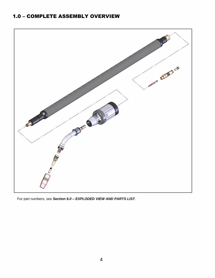
1.0 – COMPLETE ASSEMBLY OVERVIEW
For part numbers, see Section 6.0 – EXPLODED VIEW AND PARTS LIST.
LSR UNICABLE
RETAINING HEAD
THRUARM SOLID MOUNT ASSEMBLY
POWER PIN
QUICK LOAD™
LINER AND RETAINER
NECK
CONTACT TIP
NOZZLE
5
2.0 – INSTALLATION
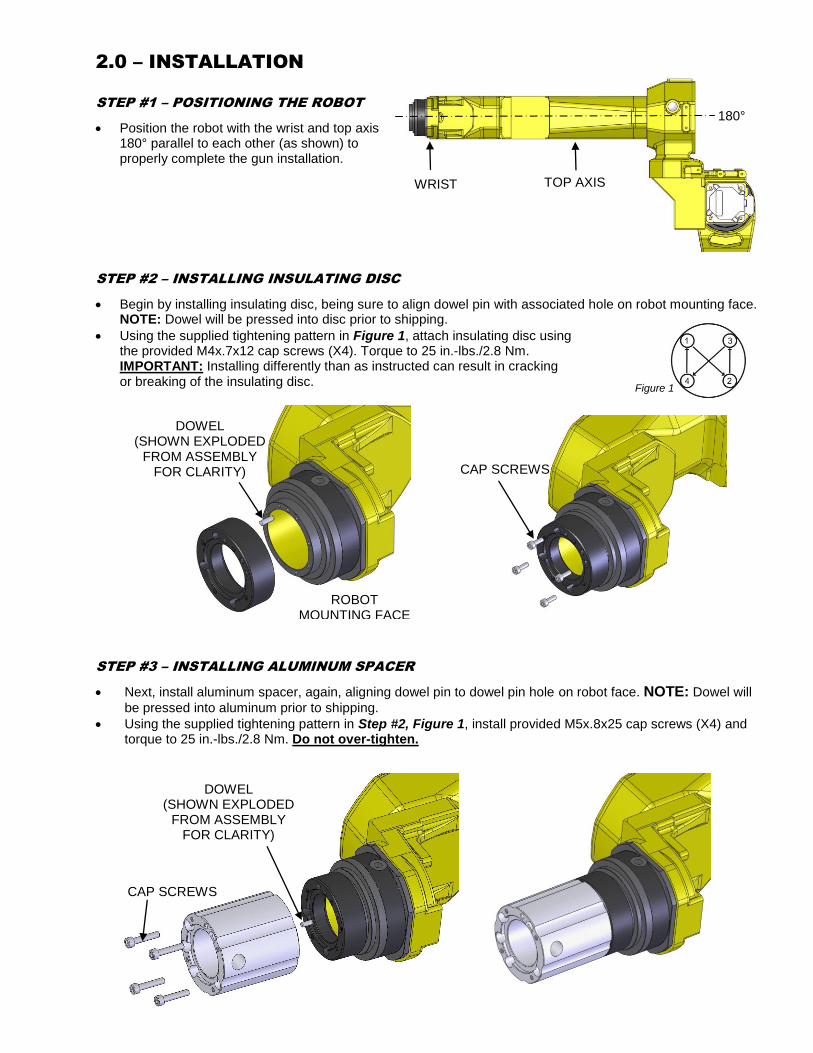
STEP #1 – POSITIONING THE ROBOT
Position the robot with the wrist and top axis 180° parallel to each other (as shown) to properly complete the gun installation.
STEP #2 – INSTALLING INSULATING DISC
Begin by installing insulating disc, being sure to align dowel pin with associated hole on robot mounting face. NOTE: Dowel will be pressed into disc prior to shipping.
Using the supplied tightening pattern in Figure 1, attach insulating disc using the provided M4x.7x12 cap screws (X4). Torque to 25 in.-lbs./2.8 Nm. IMPORTANT: Installing differently than as instructed can result in cracking or breaking of the insulating disc.
STEP #3 – INSTALLING ALUMINUM SPACER
Next, install aluminum spacer, again, aligning dowel pin to dowel pin hole on robot face. NOTE: Dowel will
be pressed into aluminum prior to shipping.
Using the supplied tightening pattern in Step #2, Figure 1, install provided M5x.8x25 cap screws (X4) and torque to 25 in.-lbs./2.8 Nm. Do not over-tighten.
DOWEL (SHOWN EXPLODED
FROM ASSEMBLY FOR CLARITY)
CAP SCREWS
DOWEL (SHOWN EXPLODED
FROM ASSEMBLY FOR CLARITY)
ROBOT MOUNTING FACE
CAP SCREWS
WRIST TOP AXIS
180°
Figure 1
6
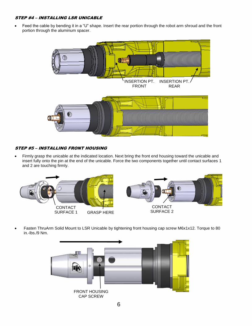
STEP #4 – INSTALLING LSR UNICABLE
Feed the cable by bending it in a “U” shape. Insert the rear portion through the robot arm shroud and the front portion through the aluminum spacer.
STEP #5 – INSTALLING FRONT HOUSING
Firmly grasp the unicable at the indicated location. Next bring the front end housing toward the unicable and insert fully onto the pin at the end of the unicable. Force the two components together until contact surfaces 1 and 2 are touching firmly.
Fasten ThruArm Solid Mount to LSR Unicable by tightening front housing cap screw M6x1x12. Torque to 80 in.-lbs./9 Nm.
INSERTION PT.
FRONT INSERTION PT.
REAR
CONTACT SURFACE 1 GRASP HERE
CONTACT SURFACE 2
FRONT HOUSING CAP SCREW
7
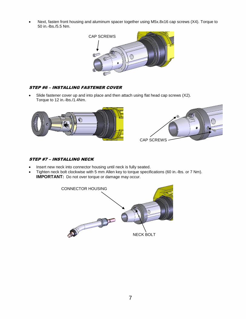
Next, fasten front housing and aluminum spacer together using M5x.8x16 cap screws (X4). Torque to 50 in.-lbs./5.5 Nm.
STEP #6 – INSTALLING FASTENER COVER
Slide fastener cover up and into place and then attach using flat head cap screws (X2). Torque to 12 in.-lbs./1.4Nm.
STEP #7 – INSTALLING NECK
Insert new neck into connector housing until neck is fully seated.
Tighten neck bolt clockwise with 5 mm Allen key to torque specifications (60 in.-lbs. or 7 Nm).
IMPORTANT: Do not over torque or damage may occur.
CAP SCREWS
CAP SCREWS
CONNECTOR HOUSING
NECK BOLT
8
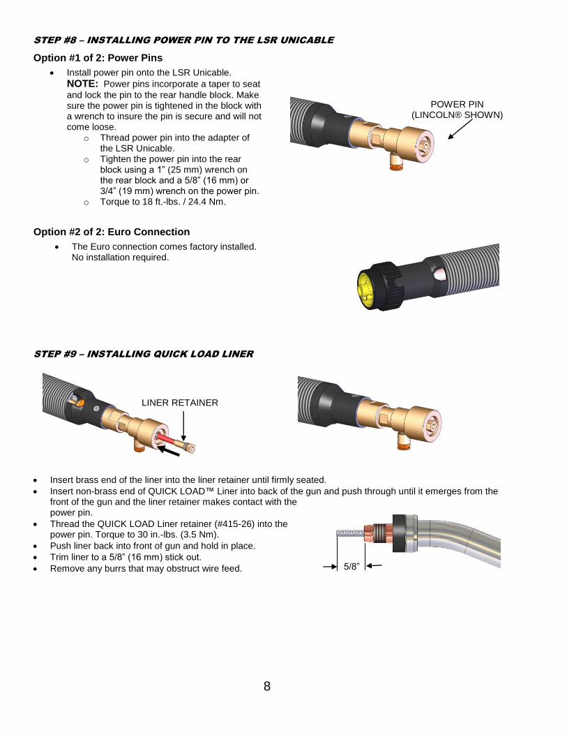
STEP #8 – INSTALLING POWER PIN TO THE LSR UNICABLE
Option #1 of 2: Power Pins
Install power pin onto the LSR Unicable.
NOTE: Power pins incorporate a taper to seat
and lock the pin to the rear handle block. Make sure the power pin is tightened in the block with a wrench to insure the pin is secure and will not come loose.
o Thread power pin into the adapter of the LSR Unicable.
o Tighten the power pin into the rear block using a 1” (25 mm) wrench on the rear block and a 5/8” (16 mm) or 3/4” (19 mm) wrench on the power pin.
o Torque to 18 ft.-lbs. / 24.4 Nm.
Option #2 of 2: Euro Connection
The Euro connection comes factory installed. No installation required.
STEP #9 – INSTALLING QUICK LOAD LINER
Insert brass end of the liner into the liner retainer until firmly seated.
Insert non-brass end of QUICK LOAD™ Liner into back of the gun and push through until it emerges from the front of the gun and the liner retainer makes contact with the power pin.
Thread the QUICK LOAD Liner retainer (#415-26) into the power pin. Torque to 30 in.-lbs. (3.5 Nm).
Push liner back into front of gun and hold in place.
Trim liner to a 5/8” (16 mm) stick out.
Remove any burrs that may obstruct wire feed.
5/8”
POWER PIN (LINCOLN® SHOWN)
LINER RETAINER
9
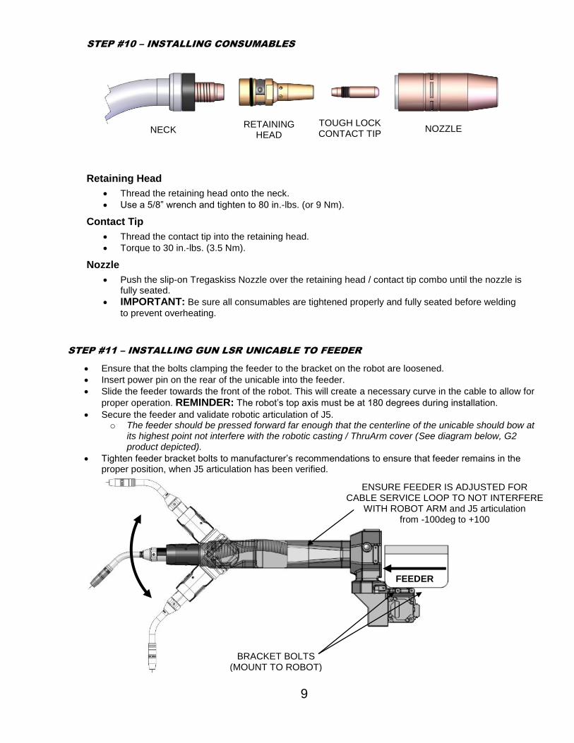
STEP #11 – INSTALLING GUN LSR UNICABLE TO FEEDER
Ensure that the bolts clamping the feeder to the bracket on the robot are loosened.
Insert power pin on the rear of the unicable into the feeder.
Slide the feeder towards the front of the robot. This will create a necessary curve in the cable to allow for
proper operation. REMINDER: The robot’s top axis must be at 180 degrees during installation.
Secure the feeder and validate robotic articulation of J5. o The feeder should be pressed forward far enough that the centerline of the unicable should bow at
its highest point not interfere with the robotic casting / ThruArm cover (See diagram below, G2 product depicted).
Tighten feeder bracket bolts to manufacturer’s recommendations to ensure that feeder remains in the proper position, when J5 articulation has been verified.
STEP #10 – INSTALLING CONSUMABLES
Retaining Head
Thread the retaining head onto the neck.
Use a 5/8” wrench and tighten to 80 in.-lbs. (or 9 Nm).
Contact Tip
Thread the contact tip into the retaining head.
Torque to 30 in.-lbs. (3.5 Nm).
Nozzle
Push the slip-on Tregaskiss Nozzle over the retaining head / contact tip combo until the nozzle is fully seated.
IMPORTANT: Be sure all consumables are tightened properly and fully seated before welding
to prevent overheating.
NECK
RETAINING HEAD
TOUGH LOCK CONTACT TIP
NOZZLE
FEEDER
BRACKET BOLTS (MOUNT TO ROBOT)
ENSURE FEEDER IS ADJUSTED FOR CABLE SERVICE LOOP TO NOT INTERFERE
WITH ROBOT ARM and J5 articulation from -100deg to +100
10
3.0 – MAINTENANCE
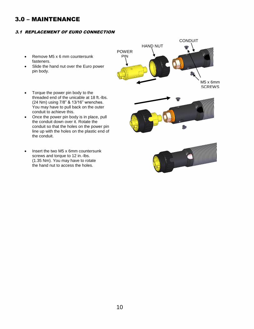
3.1 REPLACEMENT OF EURO CONNECTION
Remove M5 x 6 mm countersunk fasteners.
Slide the hand nut over the Euro power pin body.
Torque the power pin body to the threaded end of the unicable at 18 ft.-lbs. (24 Nm) using 7/8” & 13/16” wrenches. You may have to pull back on the outer conduit to achieve this.
Once the power pin body is in place, pull the conduit down over it. Rotate the conduit so that the holes on the power pin line up with the holes on the plastic end of the conduit.
Insert the two M5 x 6mm countersunk screws and torque to 12 in.-lbs. (1.35 Nm). You may have to rotate the hand nut to access the holes.
HAND NUT
POWER PIN
BODY
CONDUIT
M5 x 6mm SCREWS
11
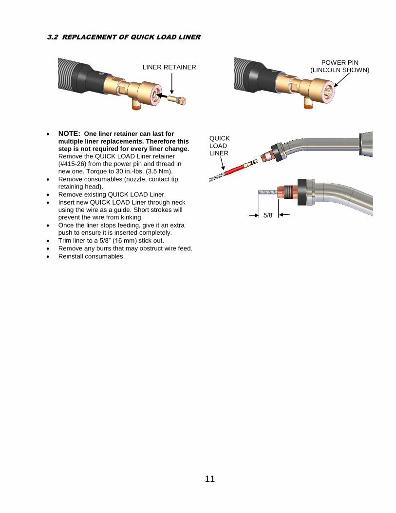
3.2 REPLACEMENT OF QUICK LOAD LINER
NOTE: One liner retainer can last for
multiple liner replacements. Therefore this step is not required for every liner change. Remove the QUICK LOAD Liner retainer (#415-26) from the power pin and thread in new one. Torque to 30 in.-lbs. (3.5 Nm).
*Ratings are based on tests that comply with IEC 60974-7 standards.
5.0 – OPTIONS
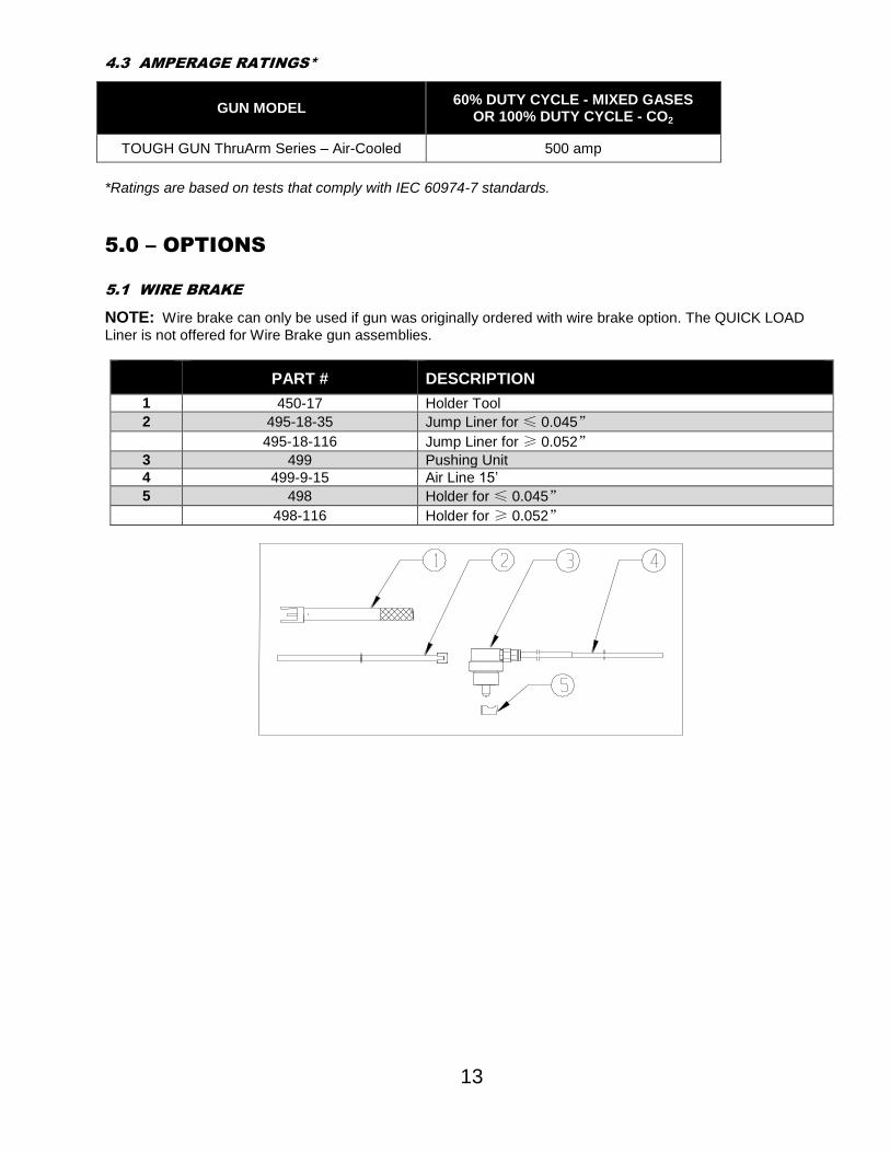
5.1 WIRE BRAKE
NOTE: Wire brake can only be used if gun was originally ordered with wire brake option. The QUICK LOAD
Liner is not offered for Wire Brake gun assemblies.
PART # DESCRIPTION
1 450-17 Holder Tool
2 495-18-35 Jump Liner for ≤ 0.045”
495-18-116 Jump Liner for ≥ 0.052”
3 499 Pushing Unit
4 499-9-15 Air Line 15’
5 498 Holder for ≤ 0.045”
498-116 Holder for ≥ 0.052”
14
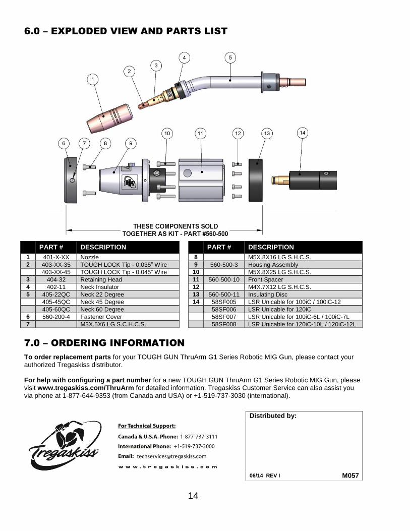
6.0 – EXPLODED VIEW AND PARTS LIST
7.0 – ORDERING INFORMATION
To order replacement parts for your TOUGH GUN ThruArm G1 Series Robotic MIG Gun, please contact your authorized Tregaskiss distributor. For help with configuring a part number for a new TOUGH GUN ThruArm G1 Series Robotic MIG Gun, please visit www.tregaskiss.com/ThruArm for detailed information. Tregaskiss Customer Service can also assist you via phone at 1-877-644-9353 (from Canada and USA) or +1-519-737-3030 (international).