M17 (Battery) Sweeper Scrubber Operator Manual 9017351 Rev. 03 (5-2017) *9017351* North America / International For the latest Parts Manuals and other language Operator Manuals, visit: www.tennantco.com/manuals ES ® Extended Scrub System Tennant True ® Parts IRIS ® a Tennant Technology Pro-Panel™ Controls Insta-Fit™ Adapter
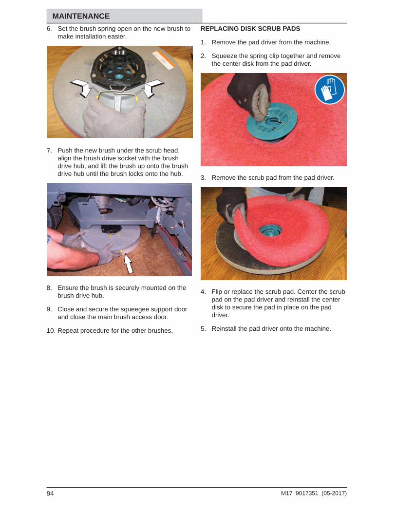
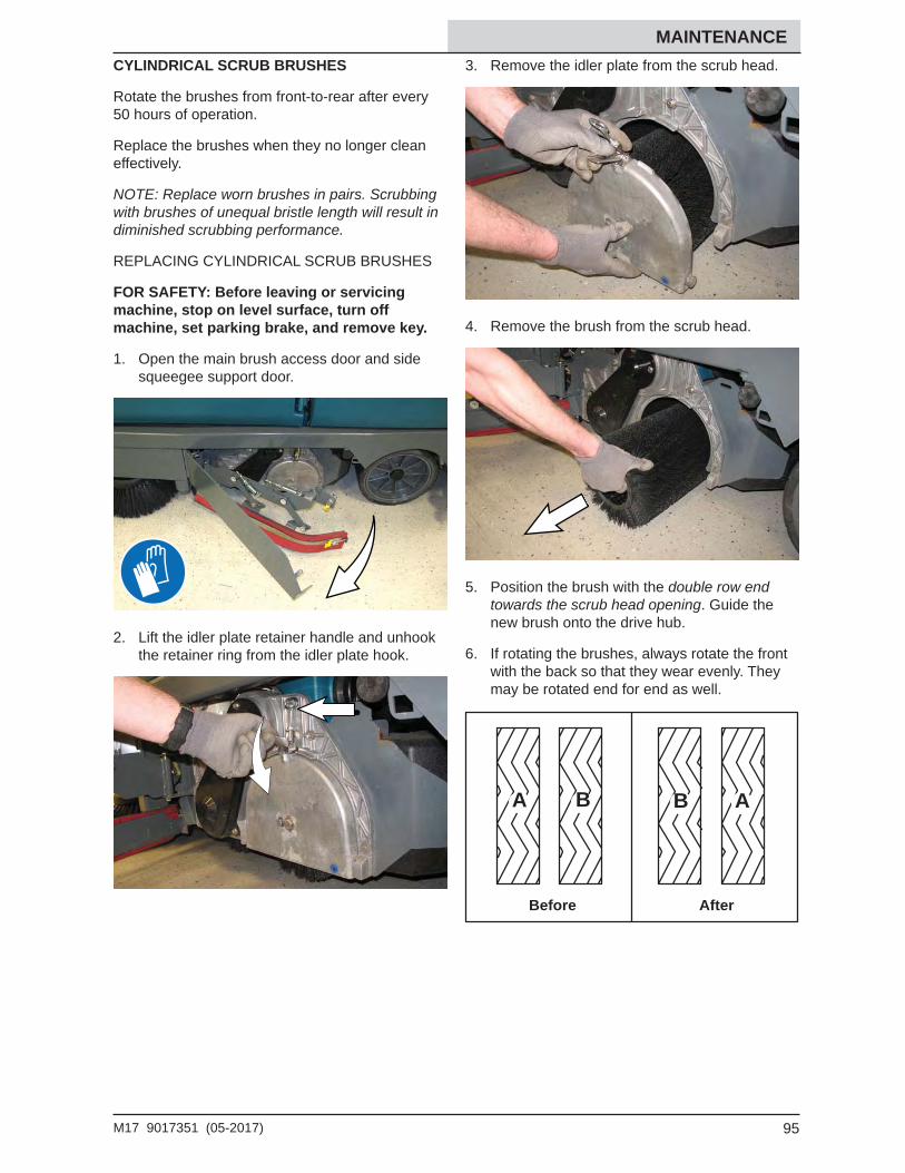
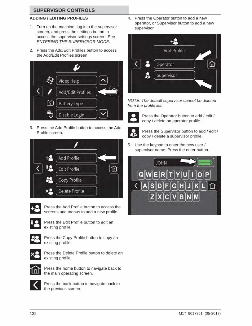
Transcript
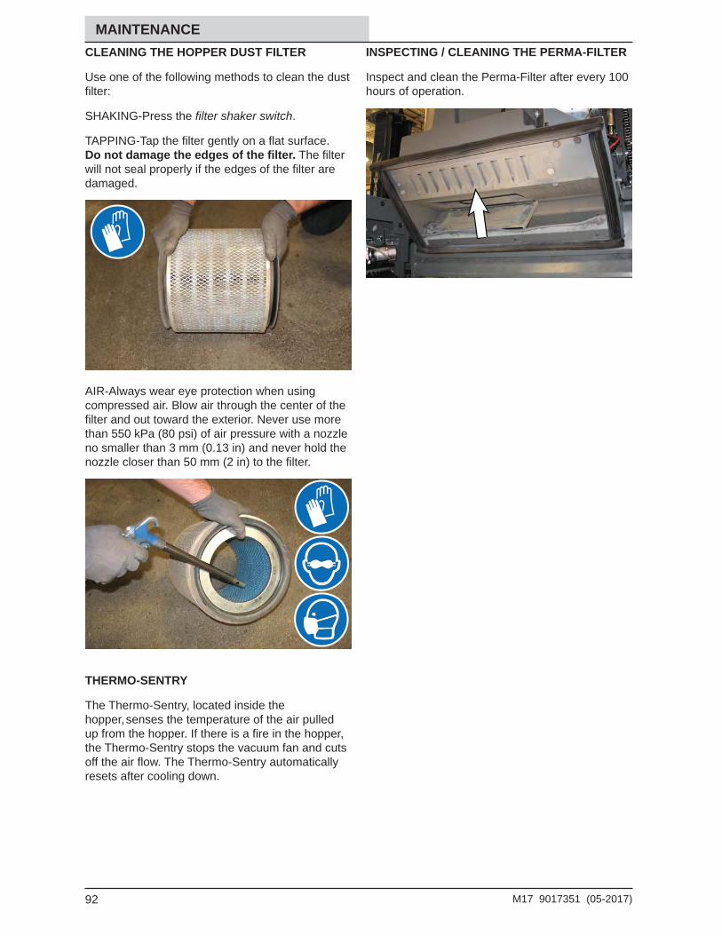
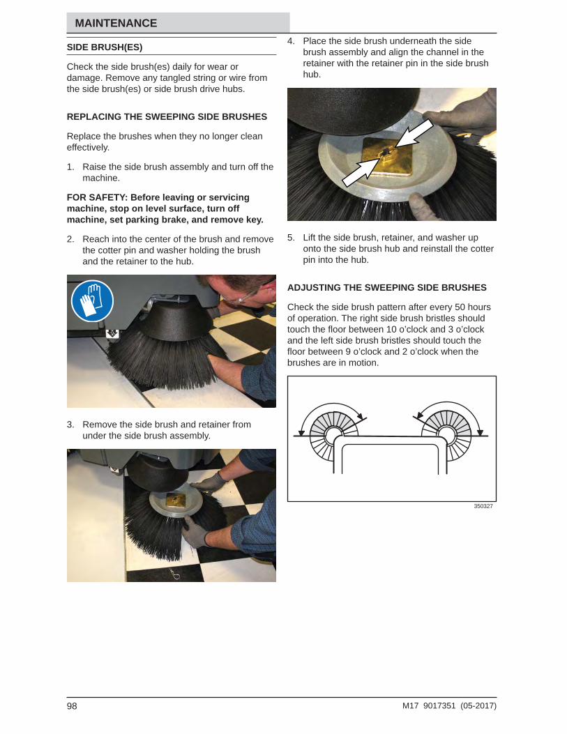
M17(Battery)
Sweeper ScrubberOperator Manual
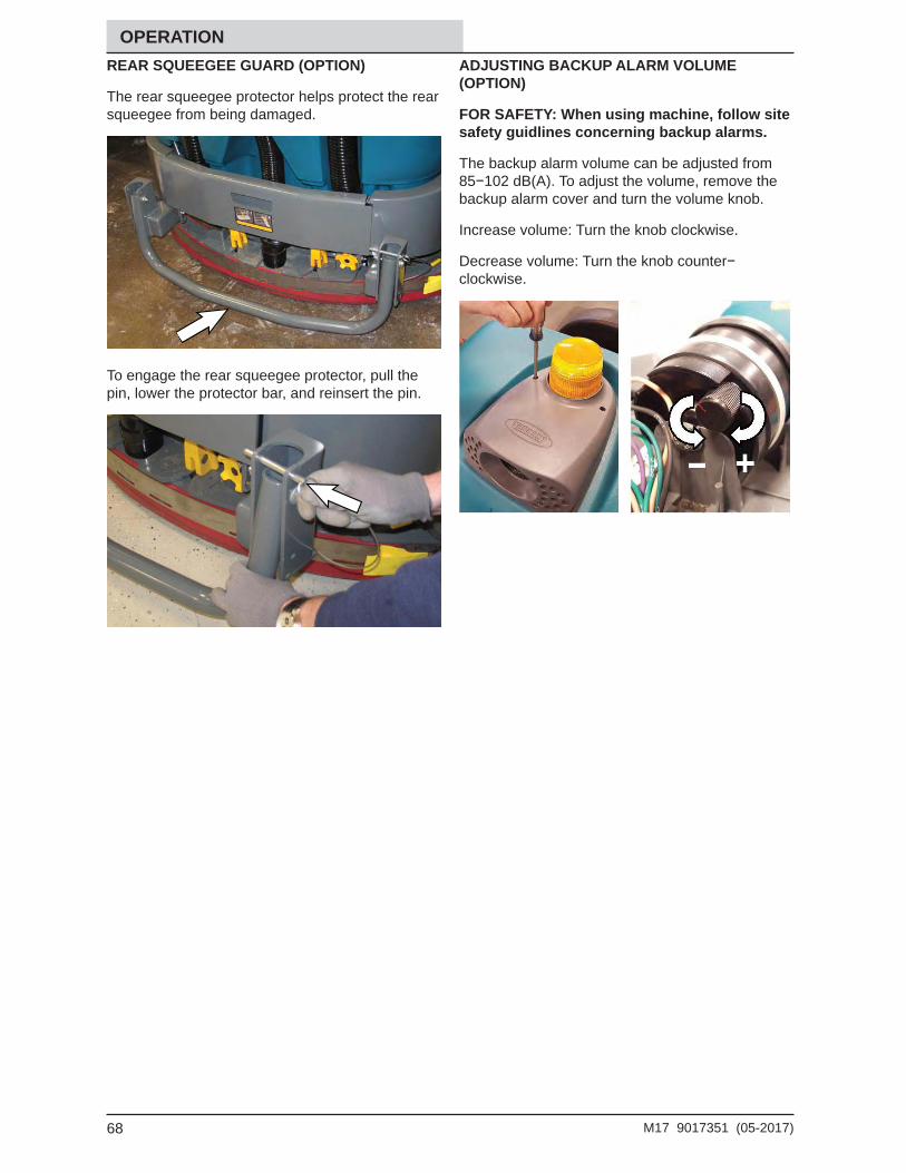
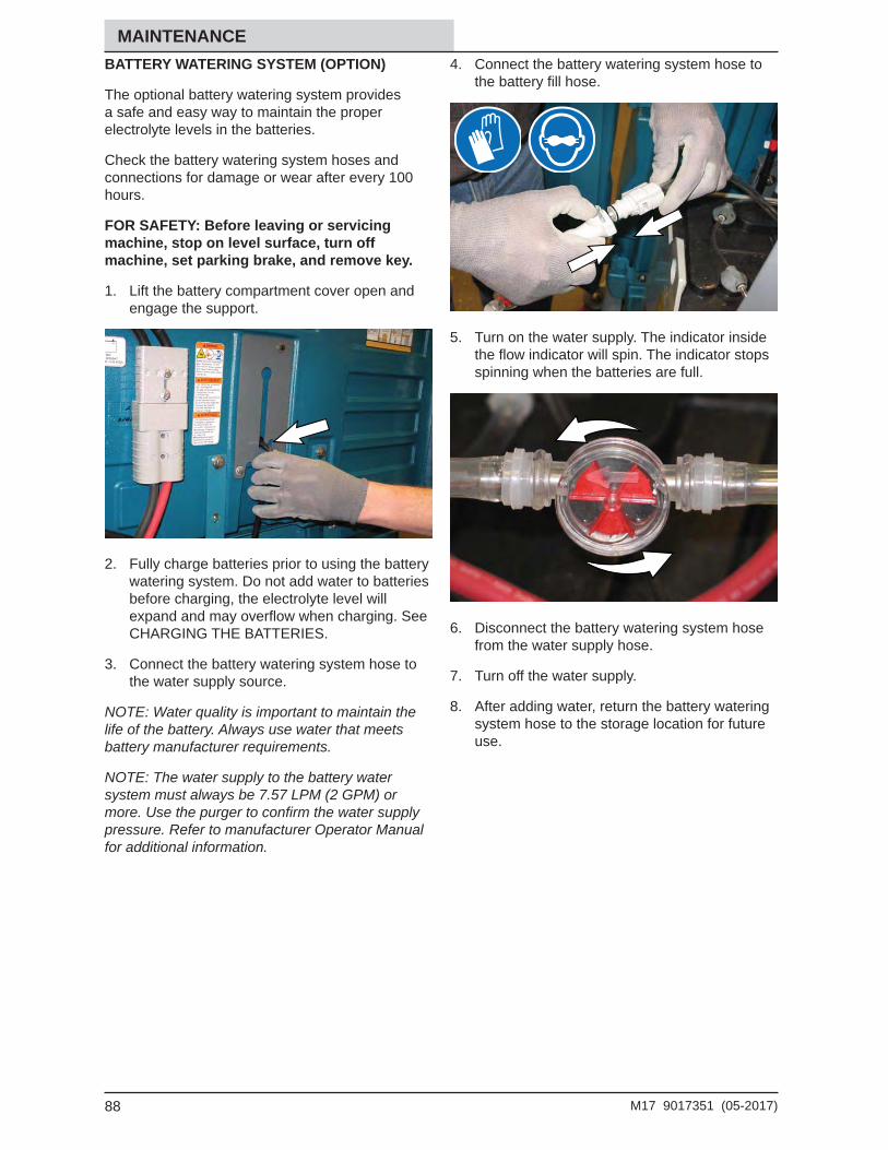
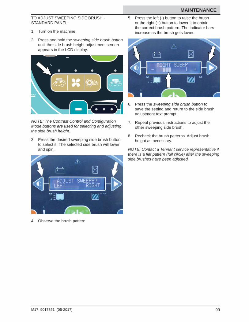
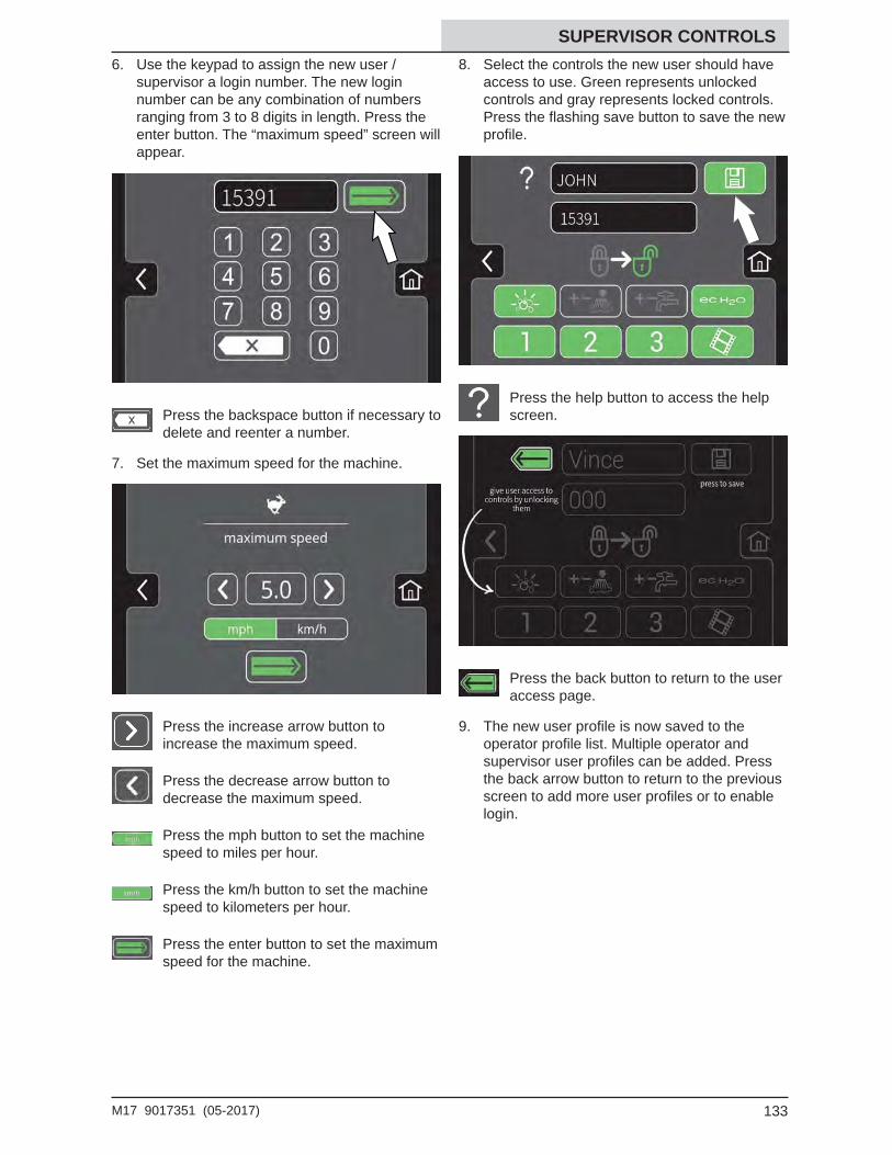
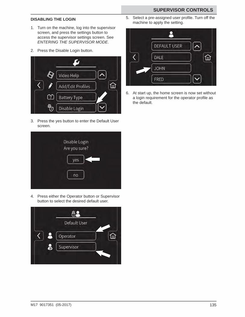
9017351Rev. 03 (5-2017)
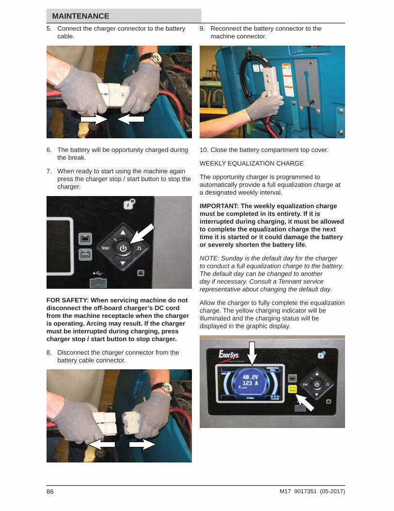
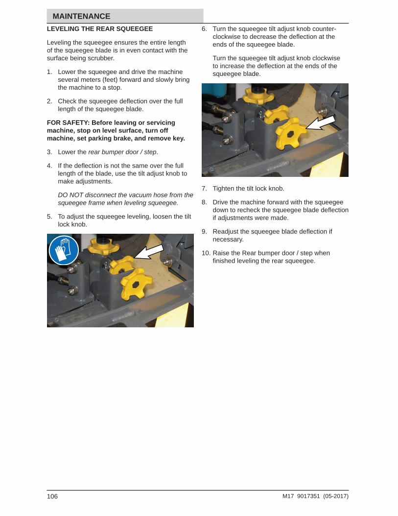
*9017351*
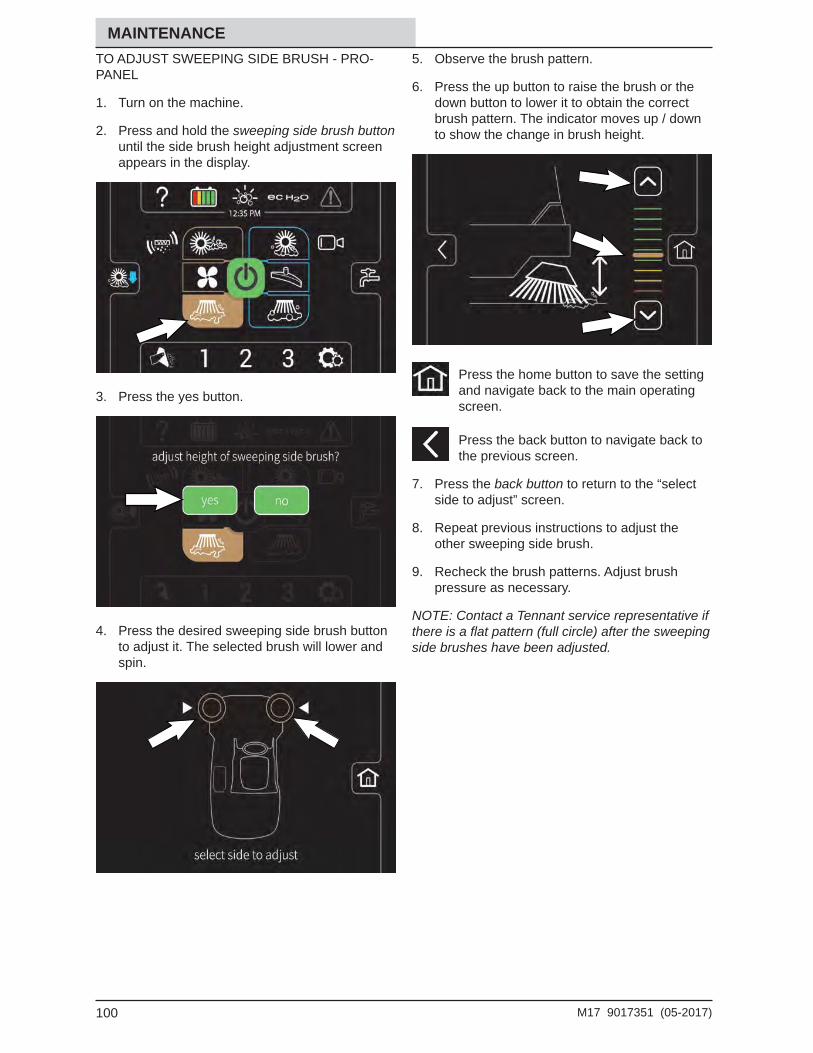
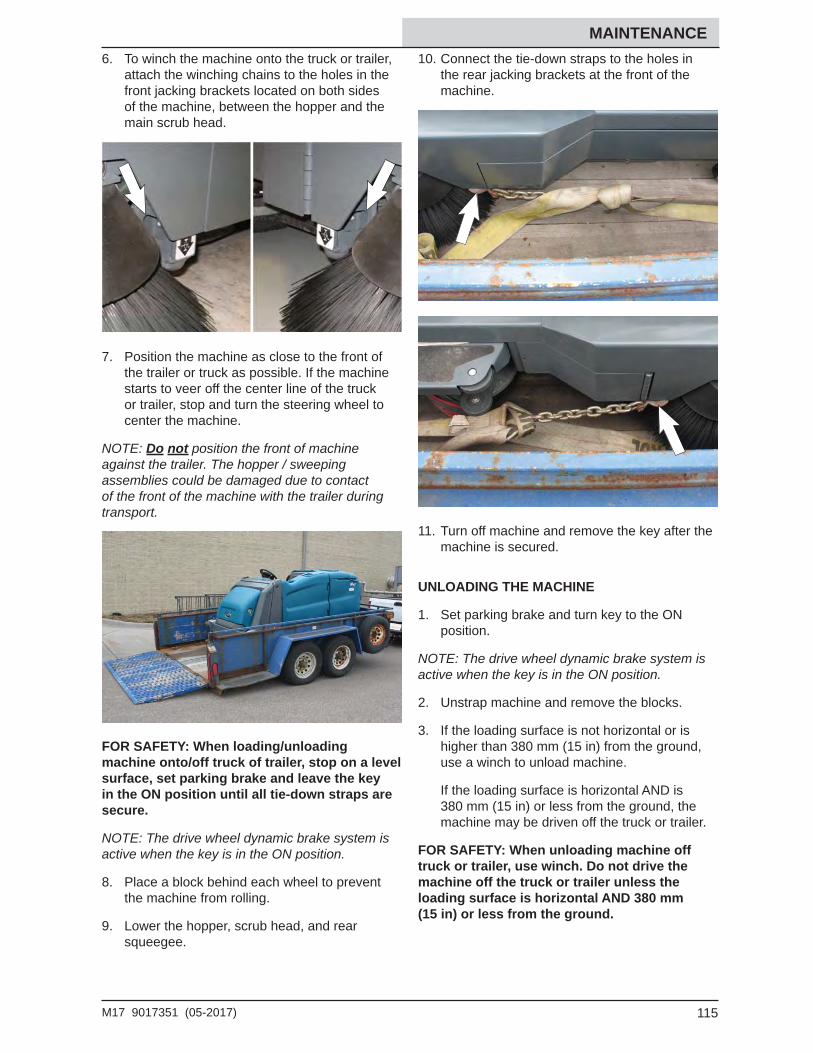
North America / InternationalFor the latest Parts Manuals and other language Operator Manuals, visit:
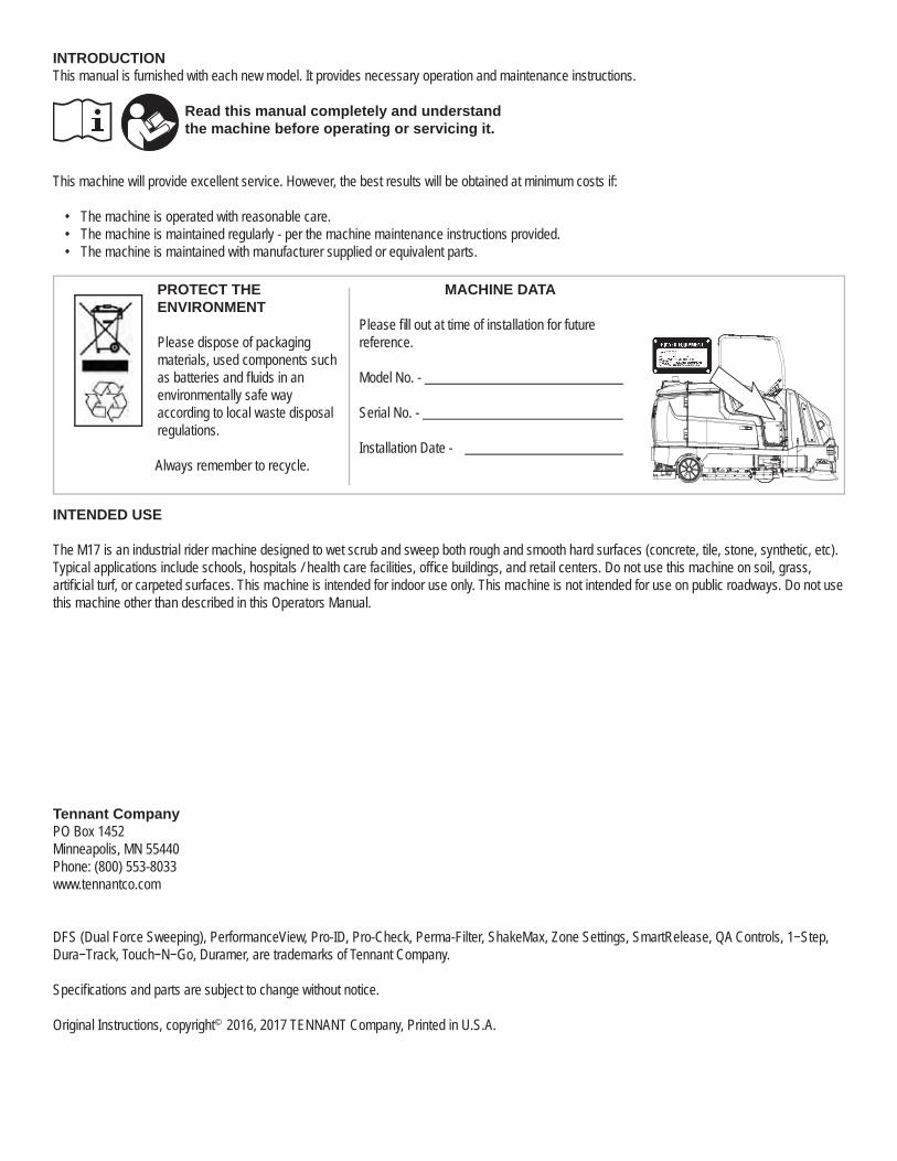
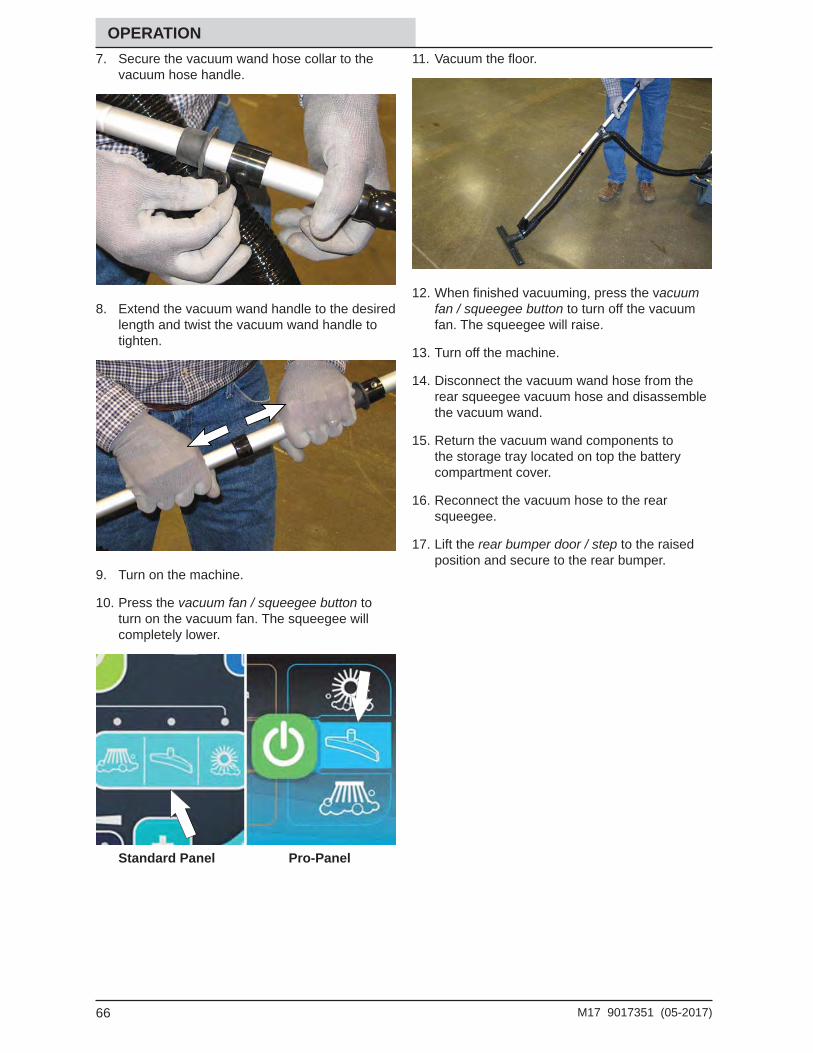
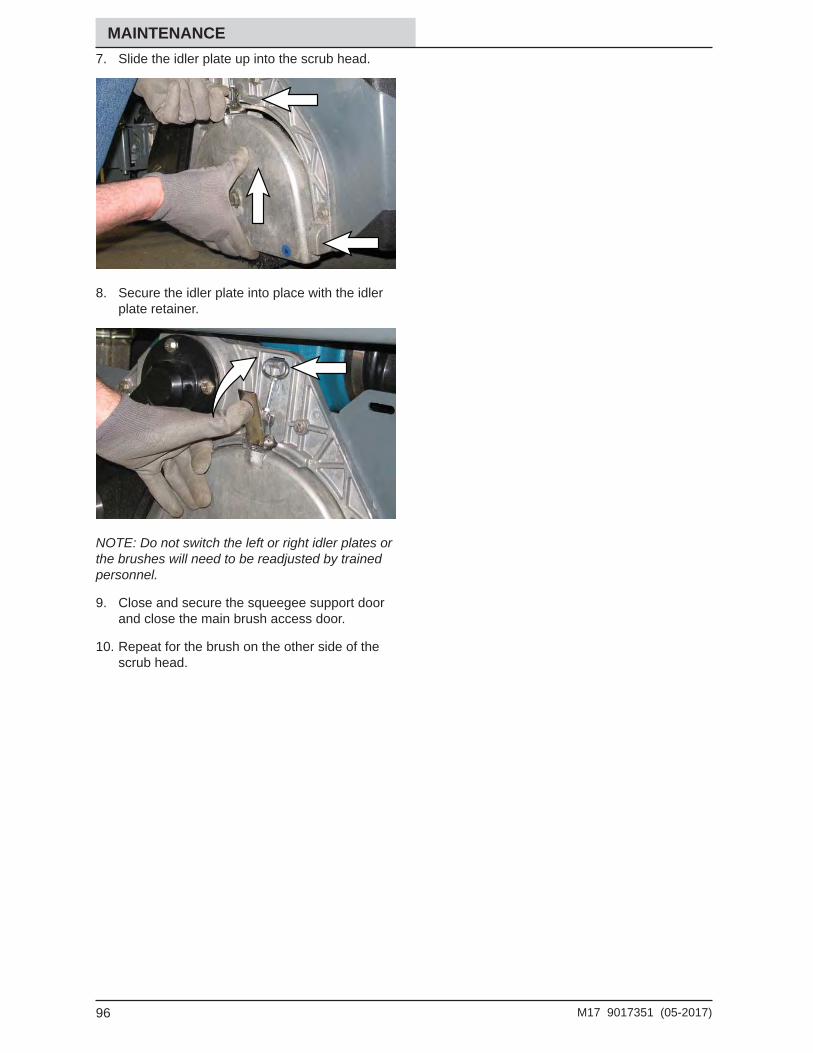
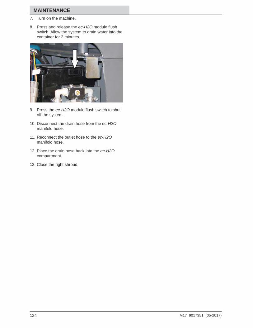
INTRODUCTIONThis manual is furnished with each new model. It provides necessary operation and maintenance instructions.
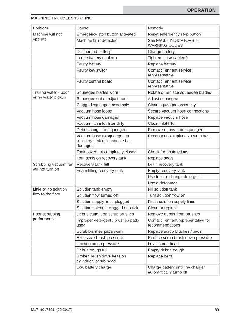
Read this manual completely and understandthe machine before operating or servicing it.
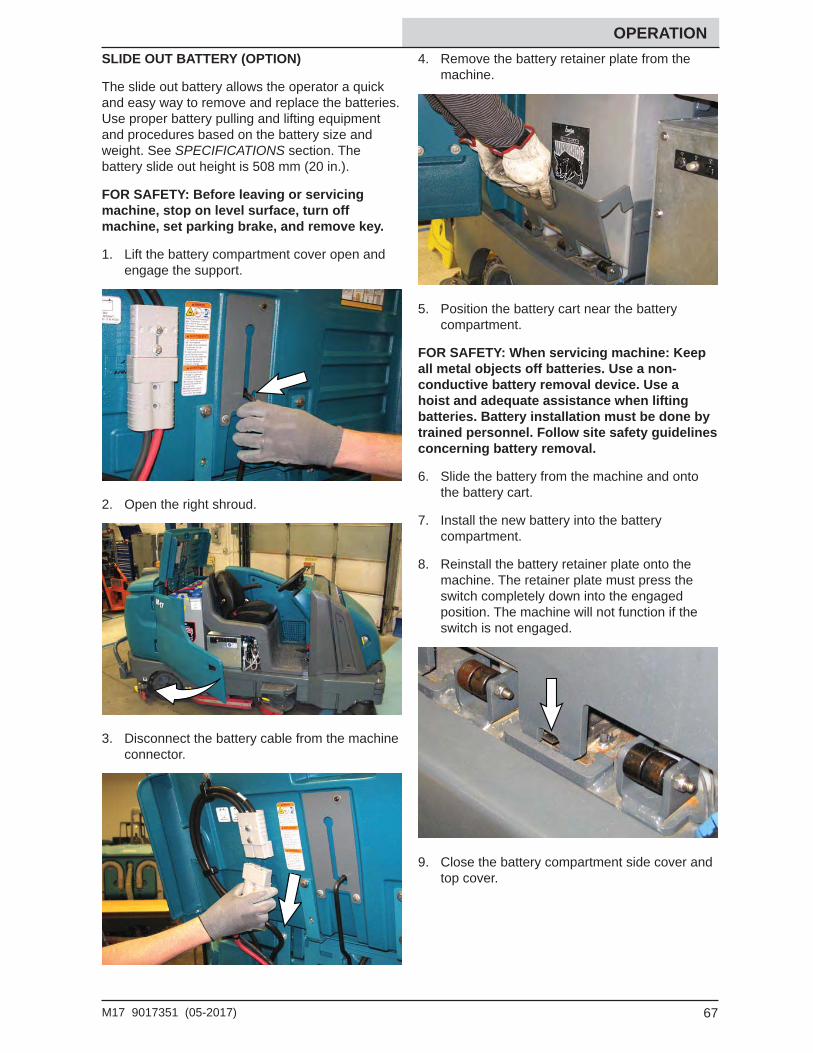
This machine will provide excellent service. However, the best results will be obtained at minimum costs if:
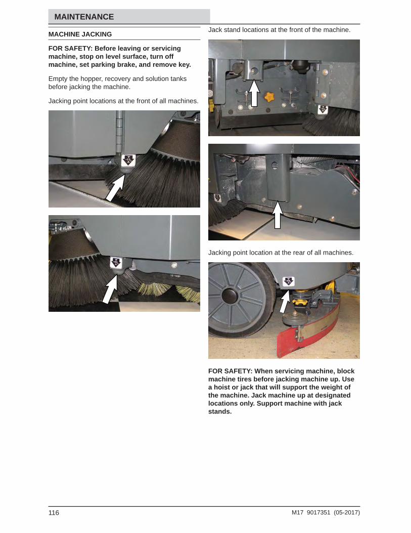
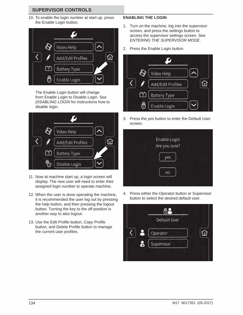
• The machine is operated with reasonable care.• The machine is maintained regularly - per the machine maintenance instructions provided.• The machine is maintained with manufacturer supplied or equivalent parts.
PROTECT THEENVIRONMENT Please dispose of packaging materials, used components such as batteries and fl uids in an environmentally safe way according to local waste disposal regulations.
Always remember to recycle.
MACHINE DATA
Please fi ll out at time of installation for future reference.
Model No. -
Serial No. -
Installation Date -
INTENDED USE
The M17 is an industrial rider machine designed to wet scrub and sweep both rough and smooth hard surfaces (concrete, tile, stone, synthetic, etc). Typical applications include schools, hospitals / health care facilities, offi ce buildings, and retail centers. Do not use this machine on soil, grass, artifi cial turf, or carpeted surfaces. This machine is intended for indoor use only. This machine is not intended for use on public roadways. Do not use this machine other than described in this Operators Manual.
CONTENTSContents ................................................................3Important Safety Instructions - Save These Instructions ............................................................7
For Safety: .................................................7Operation .............................................................12
Machine Components ...................................12Controls And Instruments ..............................13Standard Control Panel .................................14Pro-Panel Controls ........................................15Symbol Defi nition ..........................................16Operation Of Controls - Standard Panel .......19
Battery Discharge Indicator ......................19Hour Meter ...............................................19Recovery Tank Full Indicator ....................19Solution Tank Indicator .............................19Contrast Control Button ............................20Confi guration Mode Button ......................201-Step Button ...........................................20Sweeping Side Brush Button ...................21Sweeping Vacuum Fan Button .................21Sweeping Main Brush Button ...................21Scrubbing Side Brush Button (Option) .....21Scrubbing Vacuum Fan / Squeegee Button.................................22Scrubbing Main Brush Button ..................22Solution On / Off Button ...........................22Severe Environment Switch (Option) .......23Filter Shaker Switch .................................23
Operation Of Controls - Pro-Panel ................24Pro-Id Login Screen .................................24Machine Status Button .............................24Changing The Default Button ...................251-Step Button ...........................................26Sweeping Main Brush Button ...................26Sweeping Vacuum Fan Button .................26Sweeping Side Brush Button ...................27Scrubbing Main Brush Button ..................27Scrubbing Vacuum Fan / Squeegee Button.................................27Scrubbing Side Brush Button (Option) .....27Solution On / Off Button ...........................28Filter Shaker Button .................................28Severe Environment Button (Option) .......28Zone Control Buttons ...............................29Rearview Camera Button .........................29Help Button ..............................................30Video Help Button ....................................32Completing The Pro-Check
Pre-Operation Checklist ......................33Operation Of Controls - All Machines ............34
How The Machine Works ..............................37Brush And Pad Information ...........................38While Operating The Machine.......................39Pre-Operation Checklist ................................40Starting The Machine ....................................41Filling The Detergent Tank (Option) ..............41Filling The Solution Tank ...............................42
Conventional Scrubbing Mode .................42Ec-H2o Scrubbing (Ec-H2o Mode) ..........42Es (Extended Scrub) Mode - Manual Tank Fill ..................................43Auto-Fill (Option) ......................................43
Setting The Brush Pressure - Standard Panel ...................................................46
Setting The Brush Pressure - Pro-Panel ............................................46
Solution Flow ................................................47Setting The Solution Flow -
Standard Panel....................................47Setting The Solution Flow -
Pro-Panel ............................................47Scrubbing / Sweeping - Standard Panel .......48Scrubbing / Sweeping - Pro-Panel ................49Double Scrubbing .........................................50Water Pickup Mode (No Scrubbing) ..............52Stop Cleaning ...............................................52Emptying The Hopper ..................................53
Emptying The Hopper - Standard Panel....................................53
Emptying The Hopper - Pro-Panel ............................................54
Engaging The Hopper Support Bar ...............56Disengaging The Hopper Support Bar ..........56Draining And Cleaning The Recovery Tank ..57Draining And Cleaning The Solution Tank .....60
4 M17 9017351 (05-2017)
CONTENTSTurn Off The Machine ...................................61Faults / Alerts ................................................62
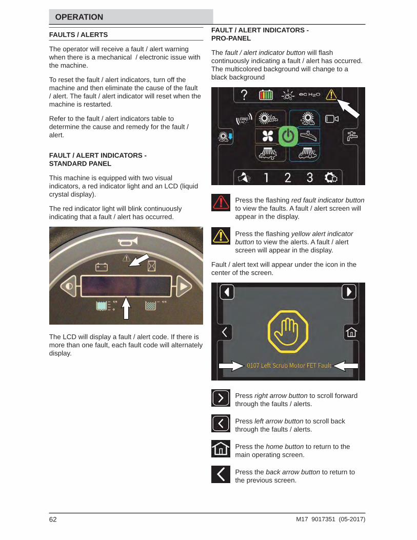
Fault / Alert Indicators - Standard Panel....................................62
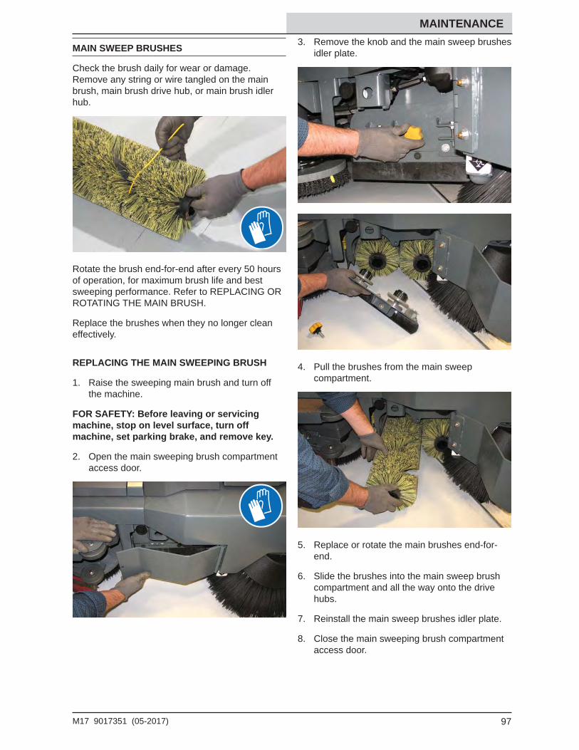
Main Sweep Brushes ....................................97Replacing The Main Sweeping Brush ......97
Side Brush(Es) ..............................................98Replacing The Sweeping Side Brushes ...98Adjusting The Sweeping Side Brushes ....98To Adjust Sweeping Side Brush - Standard Panel....................................99To Adjust Sweeping Side Brush - Pro-Panel ..........................................100Replacing The Scrubbing Side Brush
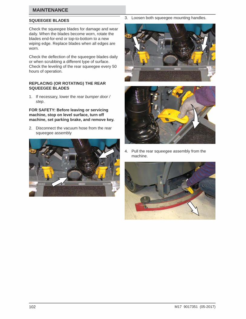
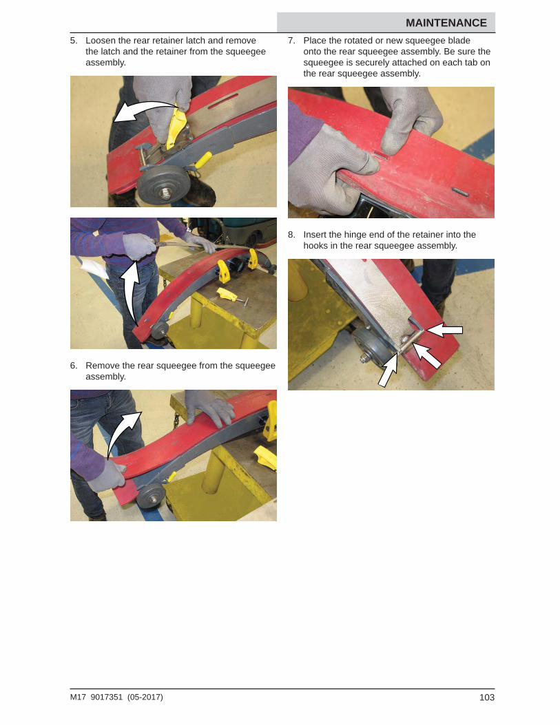
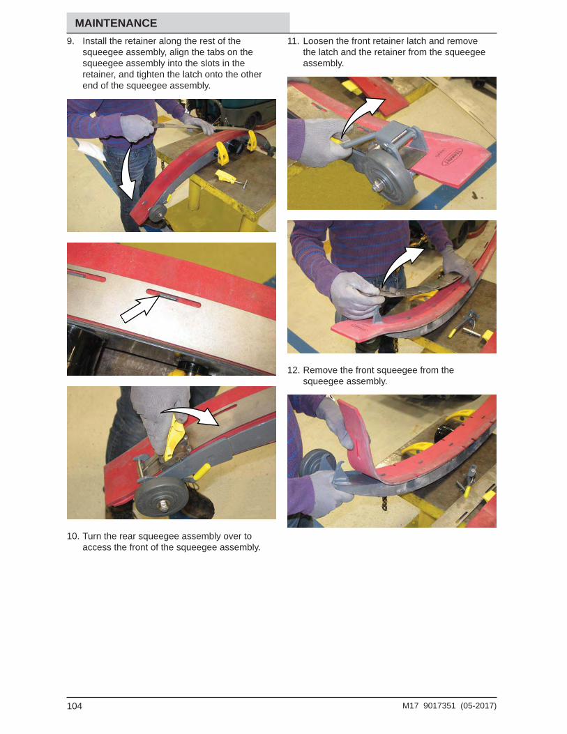
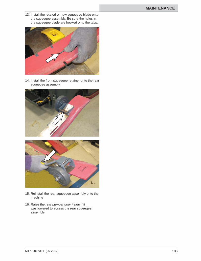
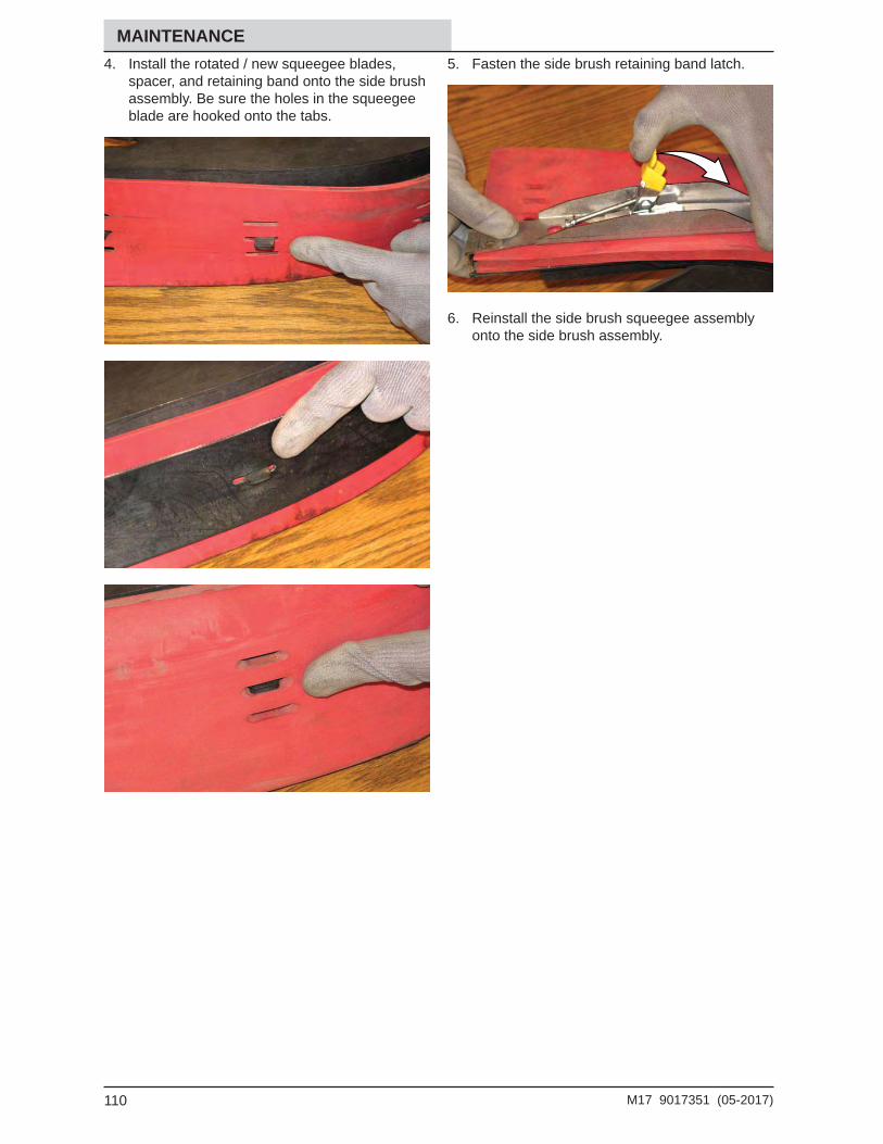
Replacing (Or Rotating) The Rear Squeegee Blades ..............................102
Leveling The Rear Squeegee ................106Adjusting The Rear Squeegee Blade
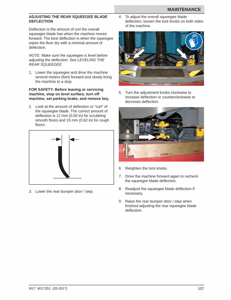
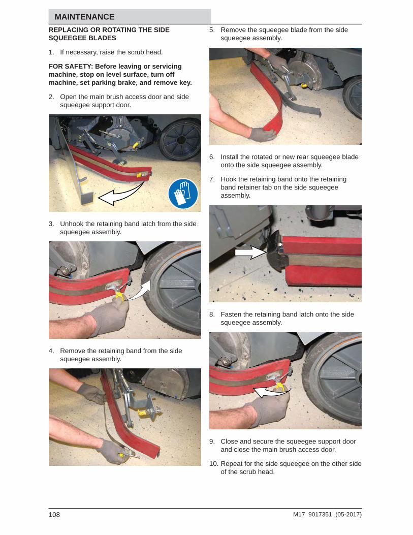
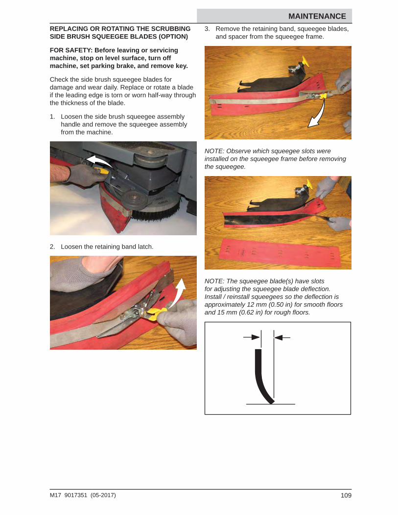
Defl ection ..........................................107Replacing Or Rotating The Side Squeegee Blades ..............................108Replacing Or Rotating The Scrubbing Side Brush Squeegee Blades (Option) .............................................109
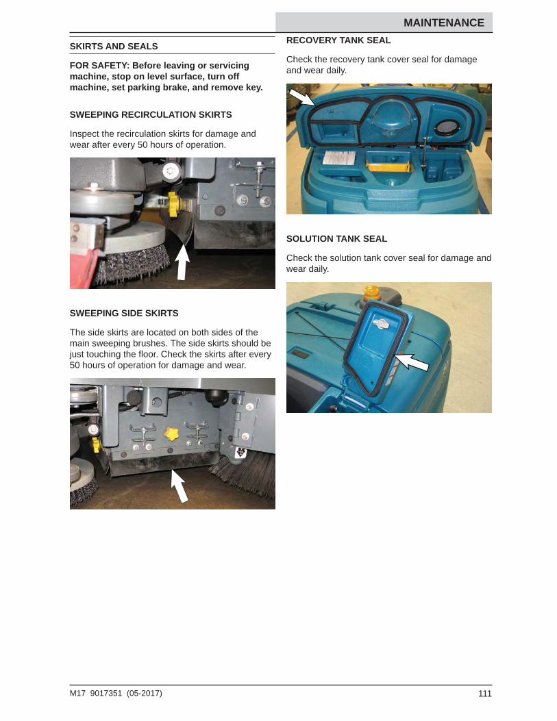
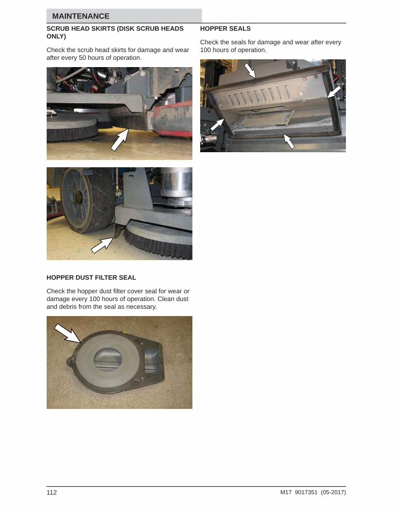
Skirts And Seals .......................................... 111Sweeping Recirculation Skirts ................ 111Sweeping Side Skirts ............................. 111Recovery Tank Seal ............................... 111Solution Tank Seal ................................. 111Scrub Head Skirts (Disk Scrub Heads Only) ...................112Hopper Dust Filter Seal ..........................112Hopper Seals .........................................112
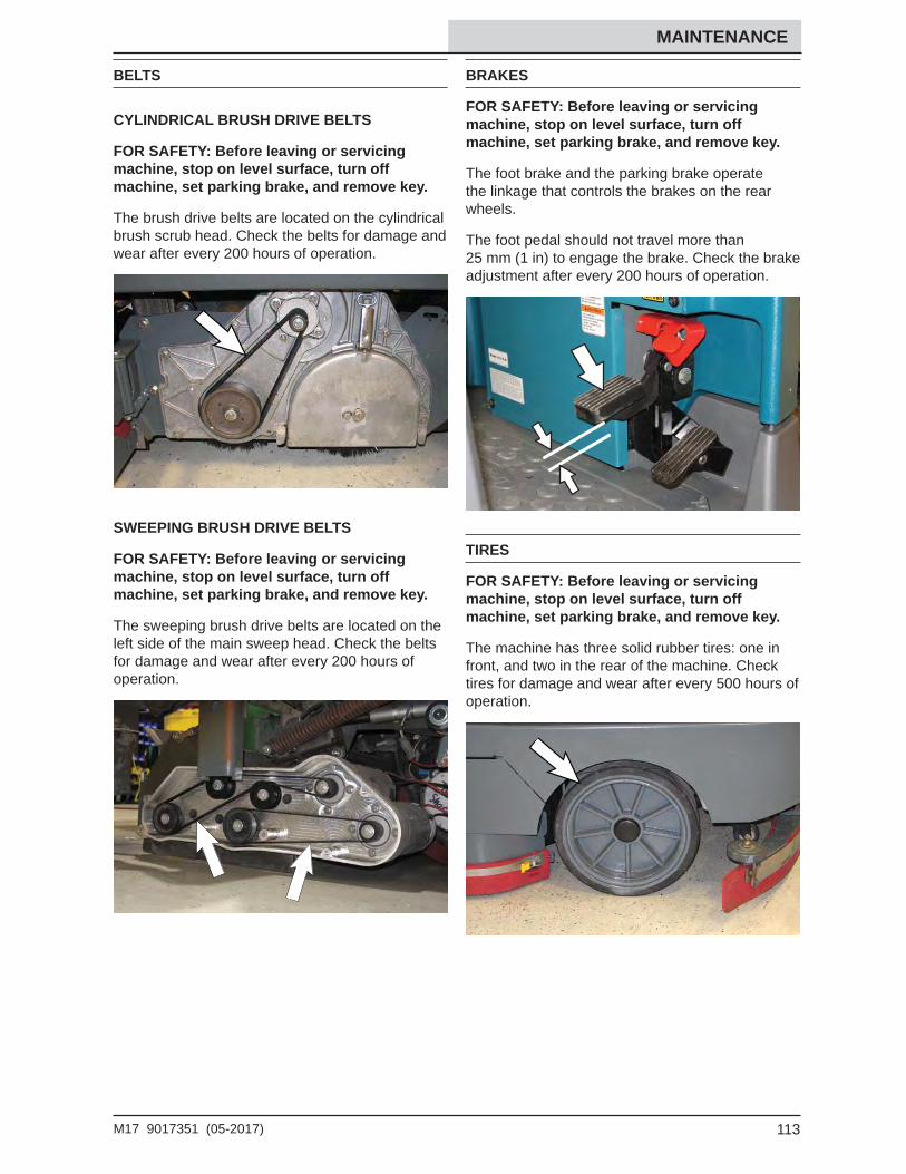
Brakes .........................................................113Tires ............................................................113Pushing, Towing, And Transporting The
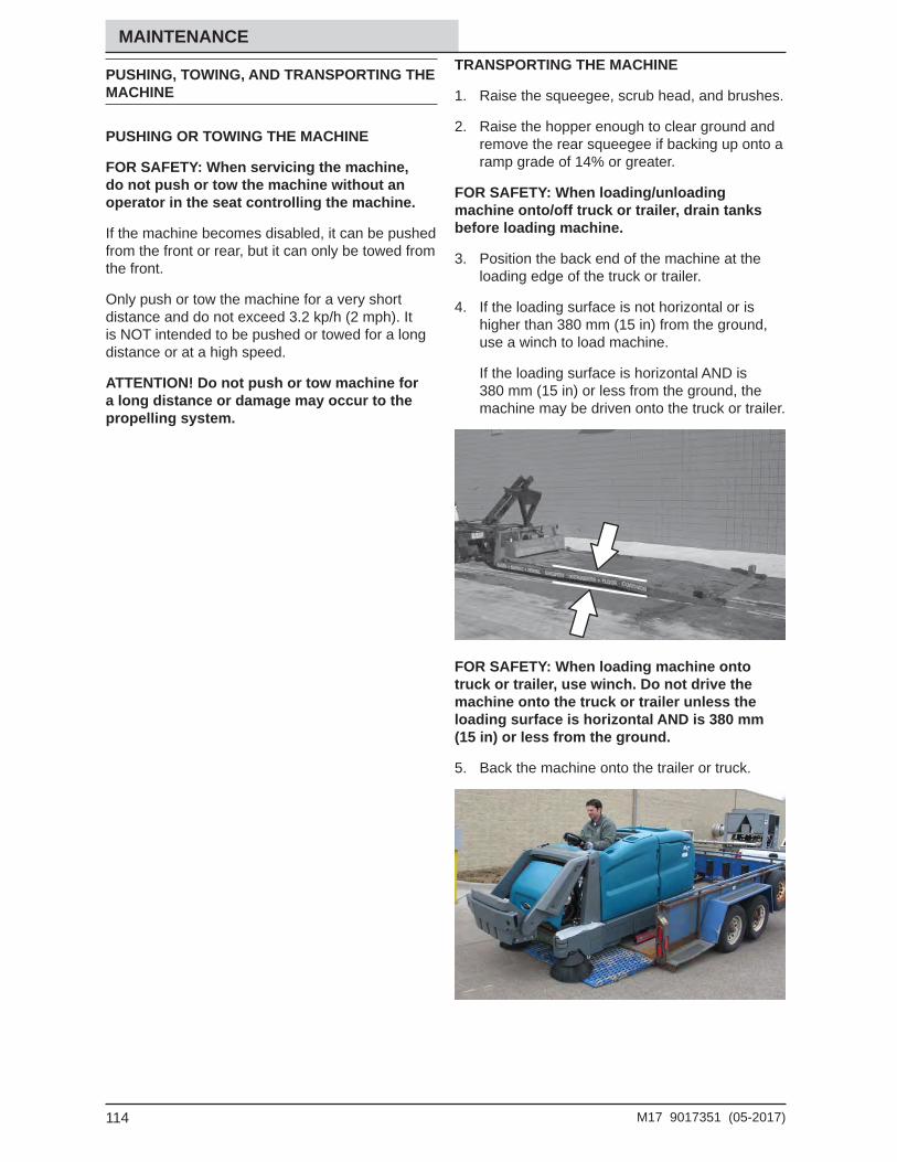
Machine ................................................114Pushing Or Towing The Machine ...........114Transporting The Machine .....................114
5M17 9017351 (05-2017)
CONTENTS
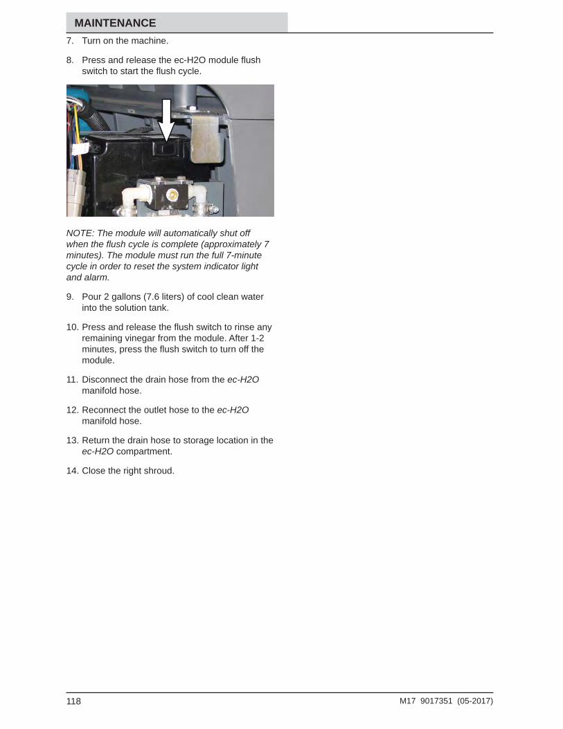
Unloading The Machine .........................115Machine Jacking .........................................116Ec-H2o Module Flush Procedure ...............117Storage Information ....................................119
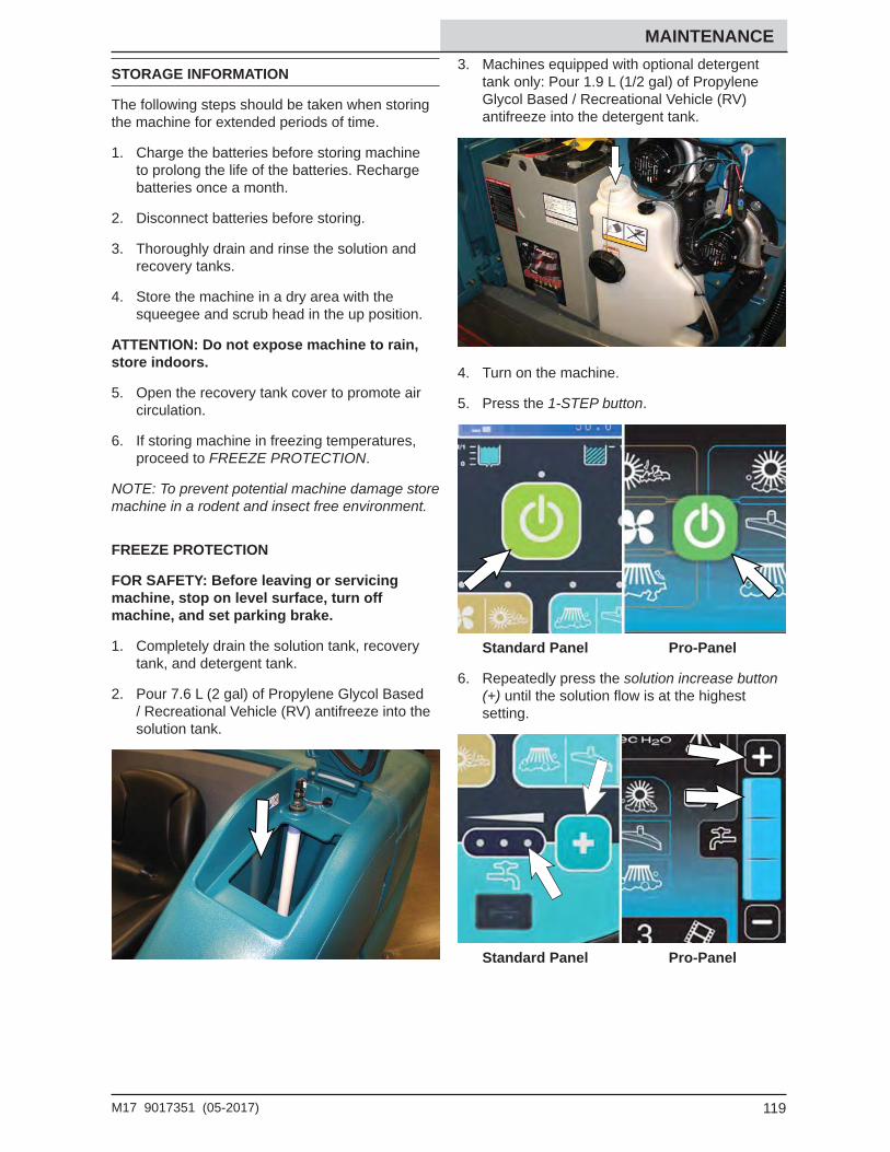
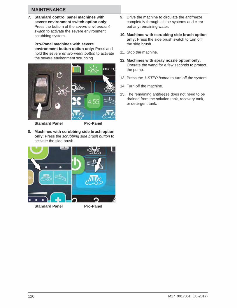
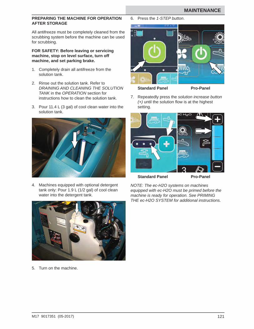
Freeze Protection ...................................119Preparing The Machine For Operation After Storage.....................121Priming The Ec-H2o System ..................123
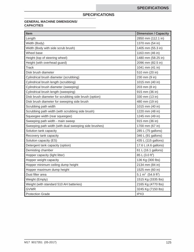
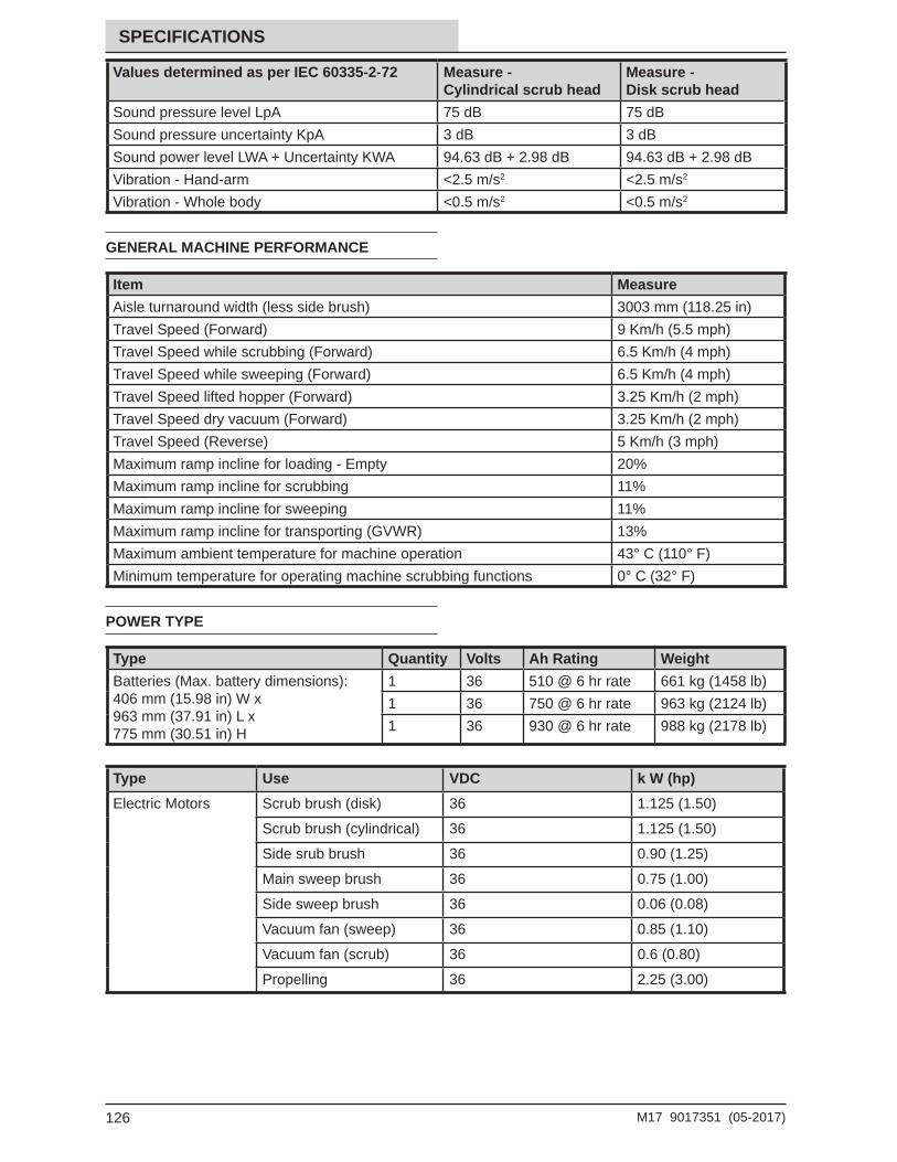
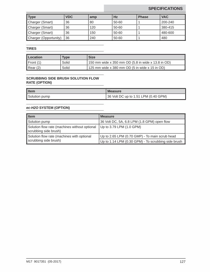
Specifi cations ....................................................125General Machine Dimensions/Capacities ...125General Machine Performance ...................126Power Type .................................................126Tires ............................................................127Scrubbing Side Brush Solution Flow Rate
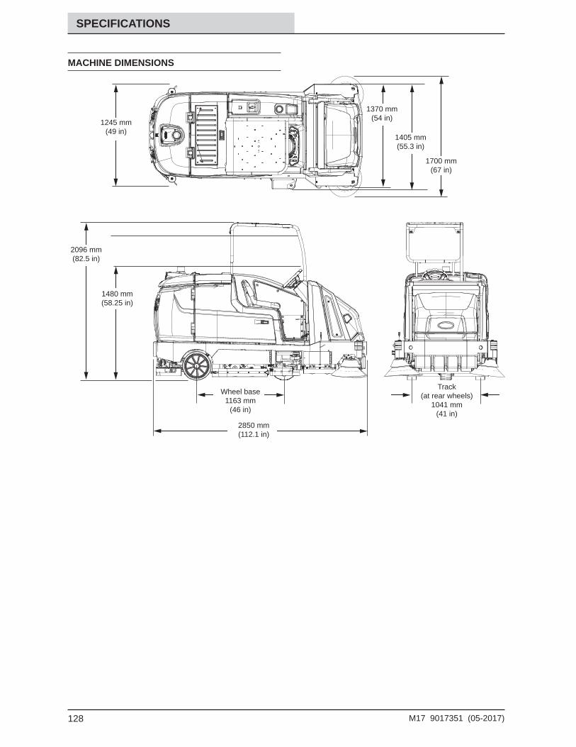
(Option) .................................................127Ec-H2o System (Option) .............................127Machine Dimensions ...................................128
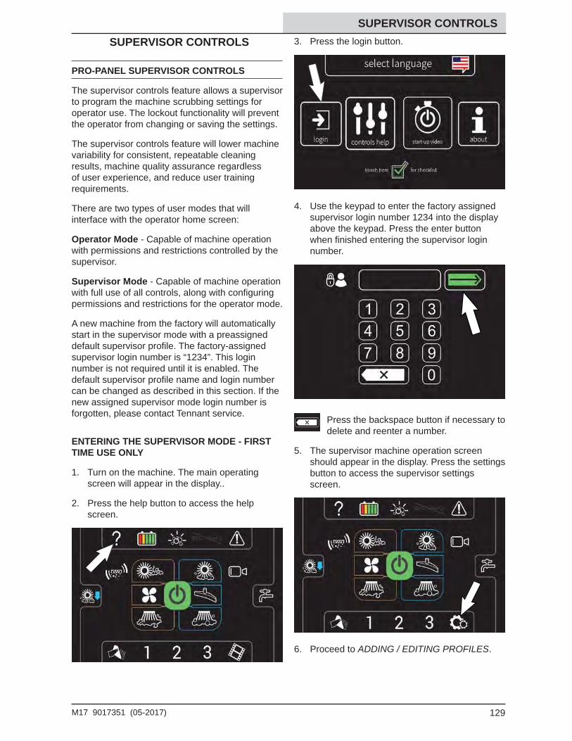
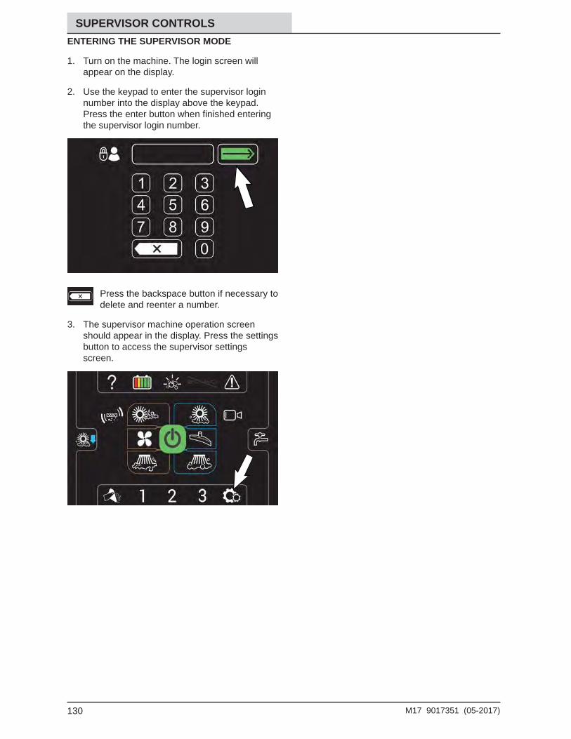
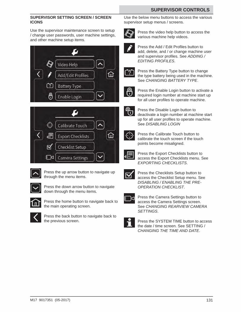
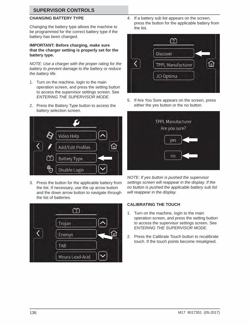
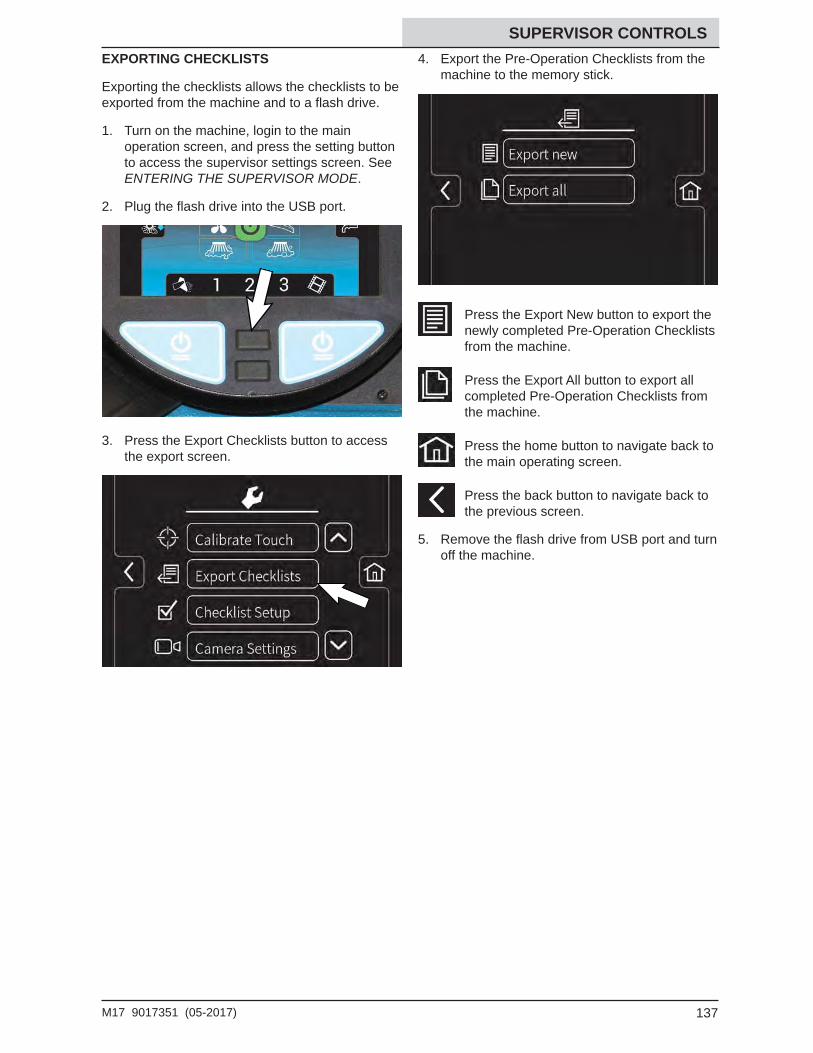
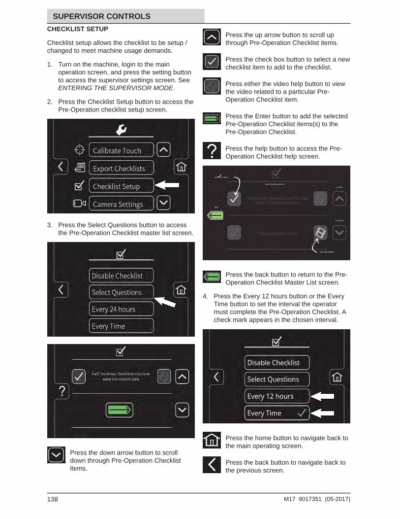
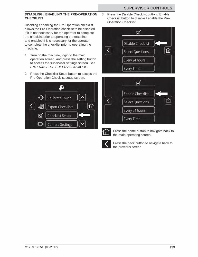
Entering The Supervisor Mode - First Time Use Only ...........................129Entering The Supervisor Mode ..............130Supervisor Setting Screen / Screen Icons .....................................131Adding / Editing Profi les .........................132Enabling The Login ................................134Disabling The Login ...............................135Changing Battery Type ...........................136Calibrating The Touch ............................136Exporting Checklists ...............................137Checklist Setup ......................................138Disabling / Enabling The Pre-Operation
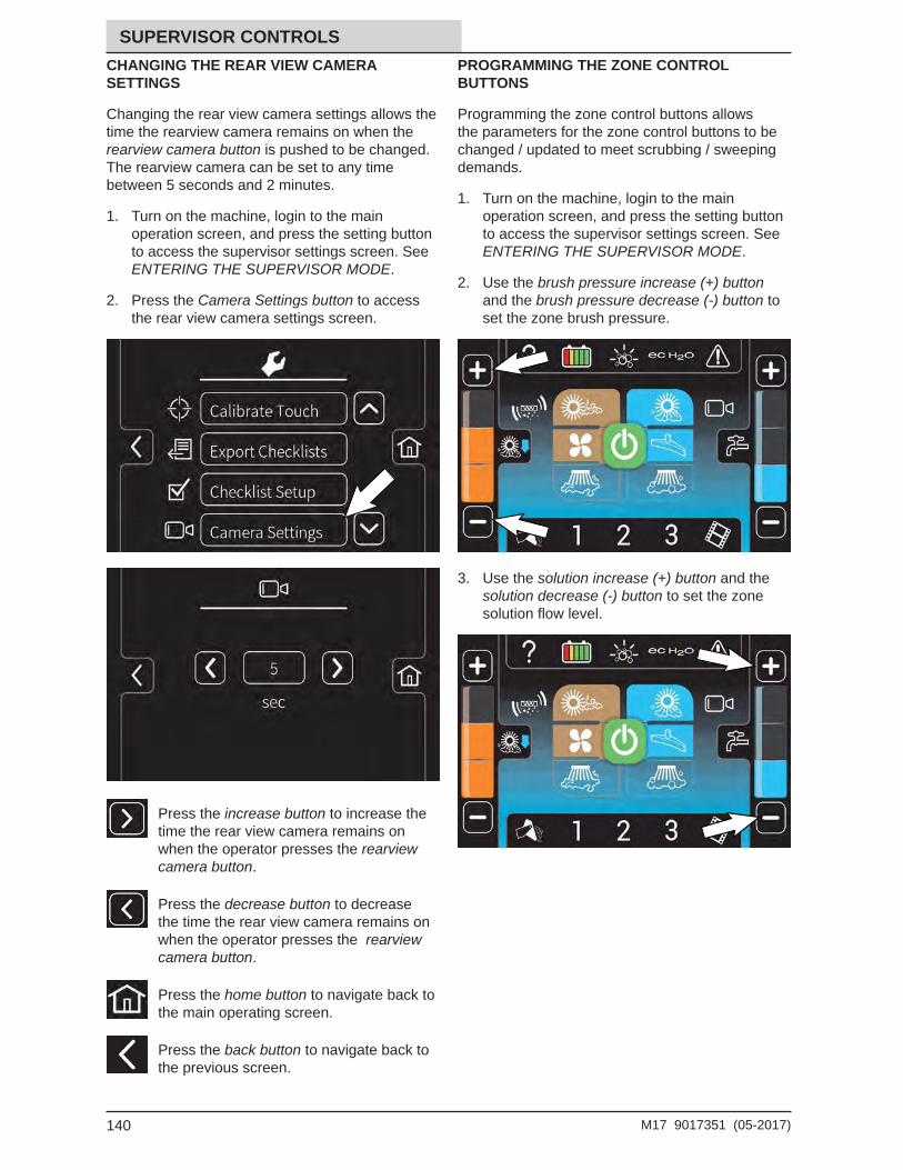
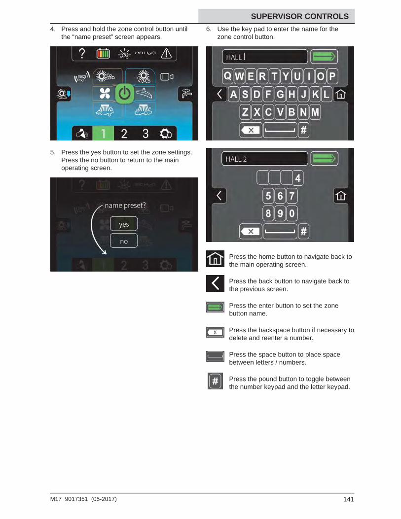
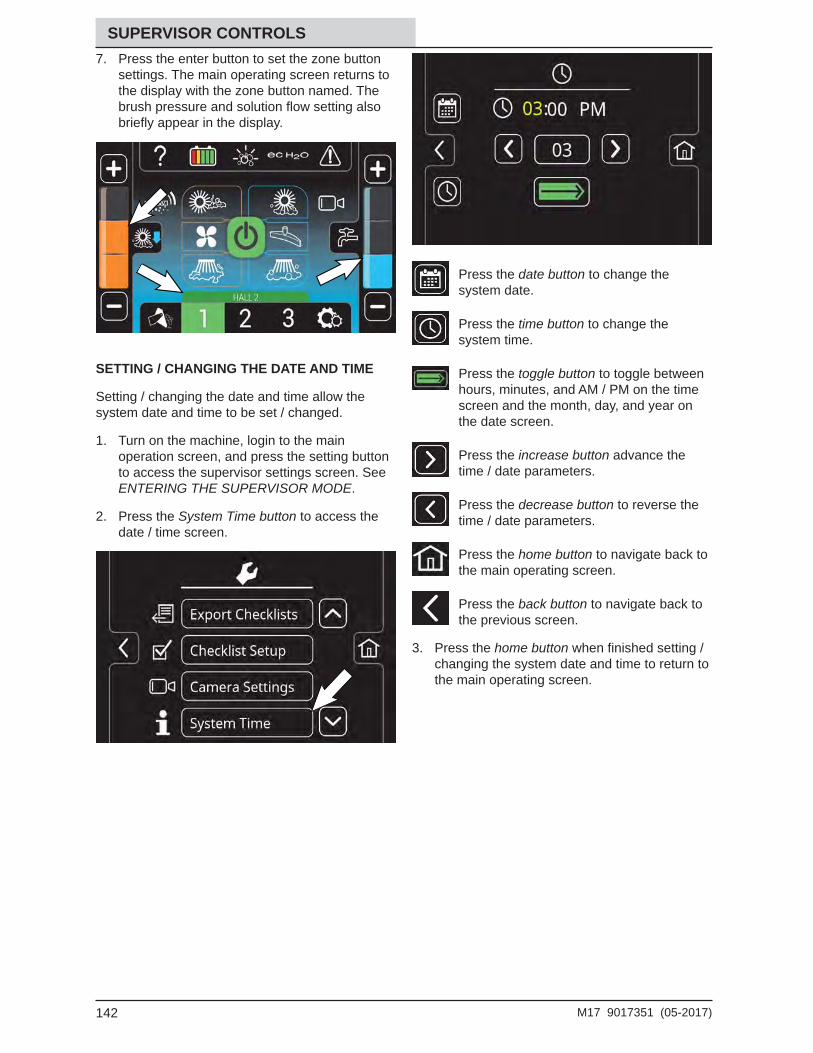
Checklist ............................................139Changing The Rear View Camera Settings................................140Programming The Zone Control Buttons 140Setting / Changing The Date And Time ..142
Index ..................................................................143
6 M17 9017351 (05-2017)
CONTENTS
7M17 9017351 (05-2017)
SAFETY
The following precautions are used throughout this manual as indicated in their descriptions:
WARNING: To warn of hazards or unsafe practices that could result in severe personal injury or death.
CAUTION: To warn of unsafe practices that could result in minor or moderate personal injury.
FOR SAFETY: To identify actions that must be followed for safe operation of equipment.
The following information signals potentially dangerous conditions to the operator. Know when these conditions can exist. Locate all safety devices on the machine. Report machine damage or faulty operation immediately..
WARNING: Batteries emit hydrogen gas. Explosion or fi re can result. Keep sparks and open fl ame away. Keep covers open when charging.
WARNING: Flammable materials can cause an explosion or fi re. Do not use fl ammable materials in tank(s).
WARNING: Flammable materials or reactive metals can cause an explosion or fi re. Do not pick up.
WARNING: Raised hopper may fall. Engage hopper support bar.
WARNING: Lift arm pinch point. Stay clear of hopper lift arms.
WARNING: Electrical Hazard
− Disconnect Battery Cables and Charger Plug Before Servicing Machine.
− Do Not Charge Batteries with Damaged Power Supply Cord. Do Not Modify Plug.
If the charger supply cord is damaged or broken, it must be replaced by the manufacturer or its service agent or a similarly qualifi ed person in order to avoid a hazard.
WARNING: This machine contains chemicals known to the state of California to cause cancer, birth defects, or other reproductive harm.
This machine may be equipped with technology that automatically communicates over the cellular network. If this machine will be operated where cell phone use is restricted because of concerns related to equipment interference, please contact a Tennant representative for information on how to disable the cellular communication functionality.
FOR SAFETY:
1. Do not operate machine: - Unless trained and authorized. - Unless operator manual is read and
understood. - Under the infl uence of alcohol or drugs. - While using a cell phone or other types of
electronic devices. - Unless mentally and physically capable of
following machine instructions. - With brake disabled. - Without fi lters in place or with clogged fi lters. - In dusty environments without the vacuum
fan on. - If it is not in proper operating condition. - With pads or accessories not supplied or
approved by Tennant. The use of other pads may impair safety.
- In outdoor areas. This machine is for indoor use only.
- In areas where fl ammable vapors/liquids or combustible dusts are present.
- In areas that are too dark to safely see the controls or operate the machine unless operating / headlights are turned on.
- In areas with possible falling objects unless equipped with overhead guard.
- With the rear bumper door / step in the lowered position.
2. Before Starting Machine: - Check machine for fl uid leaks. - Make sure all safety devices are in place
and operate properly. - Check brakes and steering for proper
operation. - Check parking brake pedal for proper
operation. - Adjust seat and fasten seat belt (if
equipped).
IMPORTANT SAFETY INSTRUCTIONS - SAVE THESE INSTRUCTIONS
8 M17 9017351 (05-2017)
SAFETY3. When using machine:
- Use only as described in this manual. - Use brakes to stop machine. - Do not pick up burning or smoking debris,
such as cigarettes, matches or hot ashes. - Go slowly on inclines and slippery surfaces. - Do not scrub on ramp inclines that exceed
11% grade or transport (GVWR) on ramp inclines that exceed 13% grade.
- Reduce speed when turning. - Keep all parts of body inside operator station
while machine is moving. - Always be aware of surroundings while
operating machine. - Do not access the video / help screens while
the machine is moving. (Pro-Panel) - Use care when reversing machine. - Move machine with care when hopper is
raised. - Make sure adequate clearance is available
before raising hopper. - Do not raise hopper when machine is on an
incline. - Keep children and unauthorized persons
away from machine. - Do not carry passengers on any part of the
machine. - Always follow safety and traffi c rules. - Report machine damage or faulty operation
immediately. - Follow mixing, handling and disposal
instructions on chemical containers. - Follow site safety guidelines concerning wet
fl oors. - Do not leave machine unattended when
fi lling solution tank with auto-fi ll feature. - Park machine on level surface when fi lling
solution tank with auto-fi ll feature.
4. Before leaving or servicing machine: - Stop on level surface. - Set parking brake. - Turn off machine and remove key.
5. When servicing machine: - All work must be done with suffi cient lighting
and visibility. - Keep work area well ventilated. - Avoid moving parts. Do not wear loose
clothing, jewelry and secure long hair. - Block machine tires before jacking machine
up. - Jack machine up at designated locations
only. Support machine with jack stands. - Use hoist or jack that will support the weight
of the machine. - Do not push or tow the machine without an
operator in the seat controlling the machine. - Do not push or tow the machine on inclines
with the brake disabled.
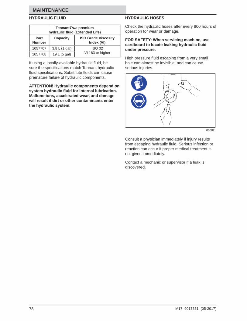
- Use cardboard to locate leaking hydraulic fl uid under pressure.
- Do not power spray or hose off machine near electrical components.
- Disconnect battery connections and charger cord before working on machine.
- Do not use incompatible battery chargers as this may damage battery packs and potentially cause a fi re.
- Inspect charger cord regularly for damage. - Do not disconnect the off−board charger’s
DC cord from the machine receptacle when the charger is operating. Arcing may result. If the charger must be interrupted during
9M17 9017351 (05-2017)
SAFETY charging, disconnect the AC power supply cord fi rst.
- Avoid contact with battery acid. - Keep all metal objects off batteries. - Use a non−conductive battery removal
device. - Use a hoist and adequate assistance when
lifting batteries. - Battery installation must be done by trained
personnel. - Follow site safety guidelines concerning
battery removal. - All repairs must be performed by a trained
service mechanic. - Do not modify the machine from its original
design. - Use Tennant supplied or approved
replacement parts. - Wear personal protective equipment as
needed and where recommended in this manual.
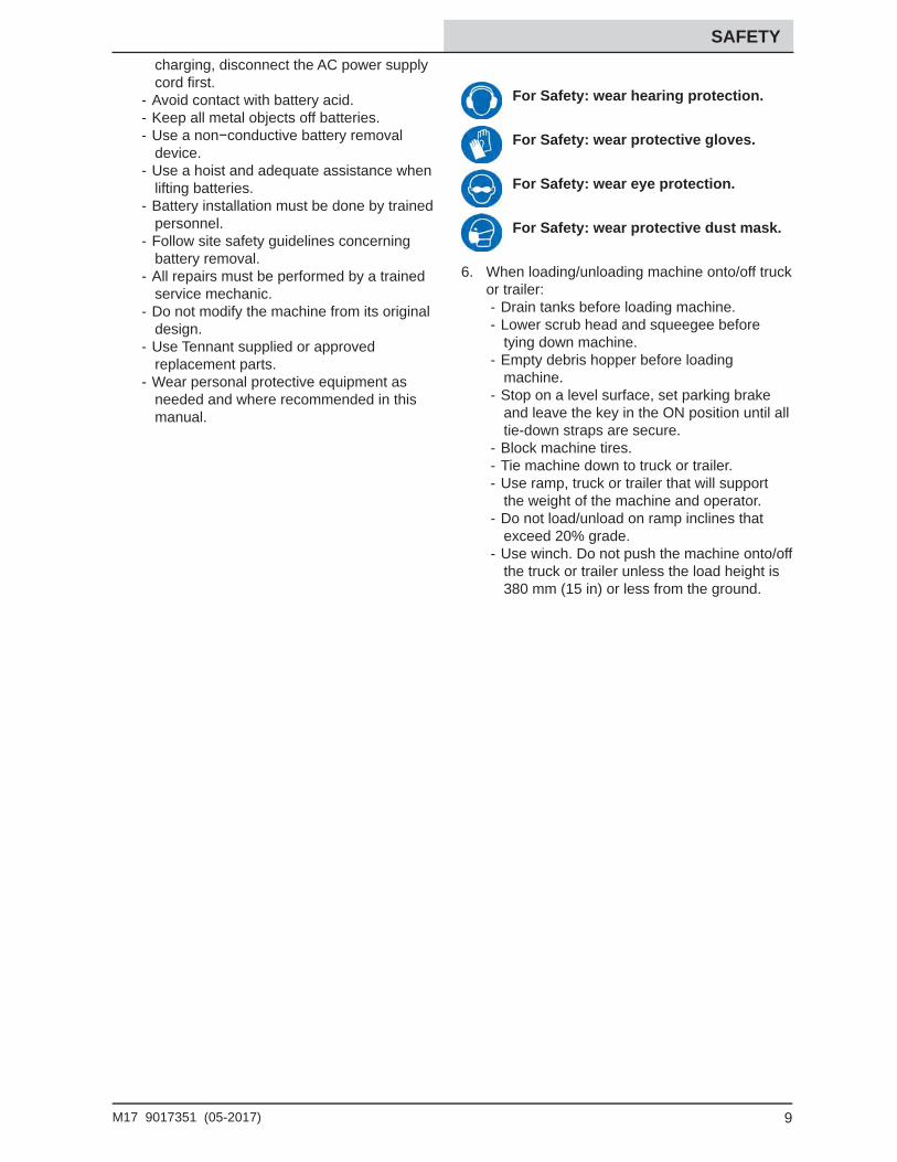
For Safety: wear hearing protection.
For Safety: wear protective gloves.
For Safety: wear eye protection.
For Safety: wear protective dust mask.
6. When loading/unloading machine onto/off truck or trailer:
- Drain tanks before loading machine. - Lower scrub head and squeegee before
tying down machine. - Empty debris hopper before loading
machine. - Stop on a level surface, set parking brake
and leave the key in the ON position until all tie-down straps are secure.
- Block machine tires. - Tie machine down to truck or trailer. - Use ramp, truck or trailer that will support
the weight of the machine and operator. - Do not load/unload on ramp inclines that
exceed 20% grade. - Use winch. Do not push the machine onto/off
the truck or trailer unless the load height is 380 mm (15 in) or less from the ground.
10 M17 9017351 (05-2017)
SAFETY
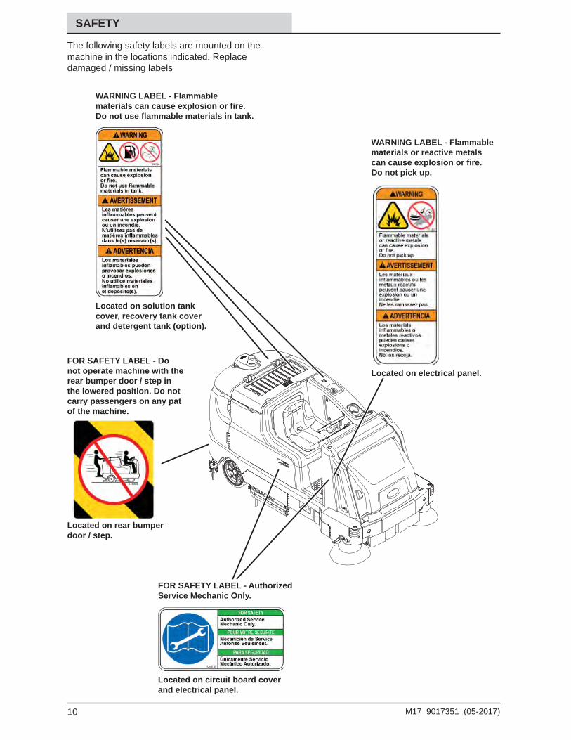
The following safety labels are mounted on the machine in the locations indicated. Replace damaged / missing labels
Located on electrical panel.
WARNING LABEL - Flammable materials or reactive metals can cause explosion or fi re. Do not pick up.
WARNING LABEL - Flammable materials can cause explosion or fi re. Do not use fl ammable materials in tank.
FOR SAFETY LABEL - Do not operate machine with the rear bumper door / step in the lowered position. Do not carry passengers on any pat of the machine.
Located on solution tank cover, recovery tank cover and detergent tank (option).
Located on rear bumper door / step.
FOR SAFETY LABEL - Authorized Service Mechanic Only.
Located on circuit board cover and electrical panel.
11M17 9017351 (05-2017)
SAFETY
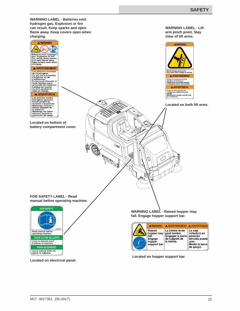
WARNING LABEL - Batteries emit hydrogen gas. Explosion or fi re can result. Keep sparks and open fl ame away. Keep covers open when charging.
Located on electrical panel.Located on hopper support bar.
Located on both lift arms.
Located on bottom of battery compartment cover.
WARNING LABEL - Lift arm pinch point. Stay clear of lift arms.
WARNING LABEL - Raised hopper may fall. Engage hopper support bar.
FOR SAFETY LABEL - Read manual before operating machine.
12 M17 9017351 (05-2017)
OPERATION
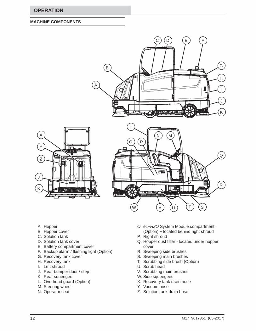
MACHINE COMPONENTS
A. HopperB. Hopper coverC. Solution tankD. Solution tank coverE. Battery compartment coverF. Backup alarm / fl ashing light (Option)G. Recovery tank coverH. Recovery tankI. Left shroudJ. Rear bumper door / stepK. Rear squeegee L. Overhead guard (Option)M. Steering wheelN. Operator seat
O. ec−H2O System Module compartment (Option) − located behind right shroud
P. Right shroudQ. Hopper dust fi lter - located under hopper
coverR. Sweeping side brushesS. Sweeping main brushesT. Scrubbing side brush (Option)U. Scrub headV. Scrubbing main brushesW. Side squeegeesX. Recovery tank drain hoseY. Vacuum hoseZ. Solution tank drain hose
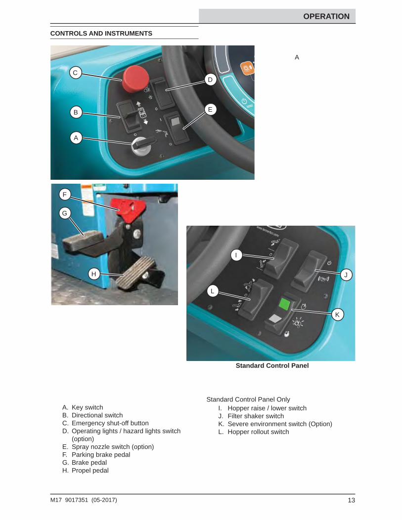
I. Hopper raise / lower switchJ. Filter shaker switchK. Severe environment switch (Option)L. Hopper rollout switch
Standard Control Panel Only
A
C
14 M17 9017351 (05-2017)
OPERATION
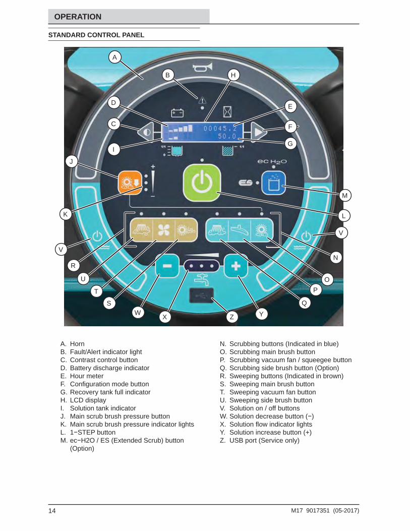
STANDARD CONTROL PANEL
A. HornB. Fault/Alert indicator lightC. Contrast control buttonD. Battery discharge indicatorE. Hour meterF. Confi guration mode buttonG. Recovery tank full indicatorH. LCD displayI. Solution tank indicatorJ. Main scrub brush pressure buttonK. Main scrub brush pressure indicator lightsL. 1−STEP buttonM. ec−H2O / ES (Extended Scrub) button
(Option)
N. Scrubbing buttons (Indicated in blue)O. Scrubbing main brush buttonP. Scrubbing vacuum fan / squeegee buttonQ. Scrubbing side brush button (Option)R. Sweeping buttons (Indicated in brown)S. Sweeping main brush buttonT. Sweeping vacuum fan buttonU. Sweeping side brush buttonV. Solution on / off buttonsW. Solution decrease button (−)X. Solution fl ow indicator lightsY. Solution increase button (+)Z. USB port (Service only)
A
B
J
K
V
D
C
I
E
F
G
H
M
L
V
ZW X Y
RN
P
QS
T
U O
15M17 9017351 (05-2017)
OPERATION
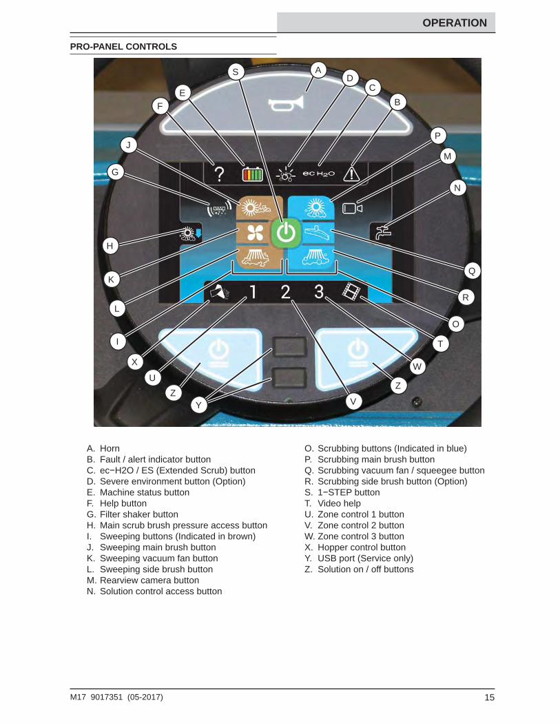
PRO-PANEL CONTROLS
A. HornB. Fault / alert indicator buttonC. ec−H2O / ES (Extended Scrub) buttonD. Severe environment button (Option)E. Machine status buttonF. Help buttonG. Filter shaker buttonH. Main scrub brush pressure access buttonI. Sweeping buttons (Indicated in brown)J. Sweeping main brush buttonK. Sweeping vacuum fan buttonL. Sweeping side brush buttonM. Rearview camera buttonN. Solution control access button
O. Scrubbing buttons (Indicated in blue)P. Scrubbing main brush buttonQ. Scrubbing vacuum fan / squeegee buttonR. Scrubbing side brush button (Option)S. 1−STEP buttonT. Video helpU. Zone control 1 buttonV. Zone control 2 buttonW. Zone control 3 buttonX. Hopper control buttonY. USB port (Service only)Z. Solution on / off buttons
A
R
W
B
D CE
F
ZU
X
Y V
Z
K
L
J
G
H
N
M
Q
P
S
I
O
T
16 M17 9017351 (05-2017)
OPERATION
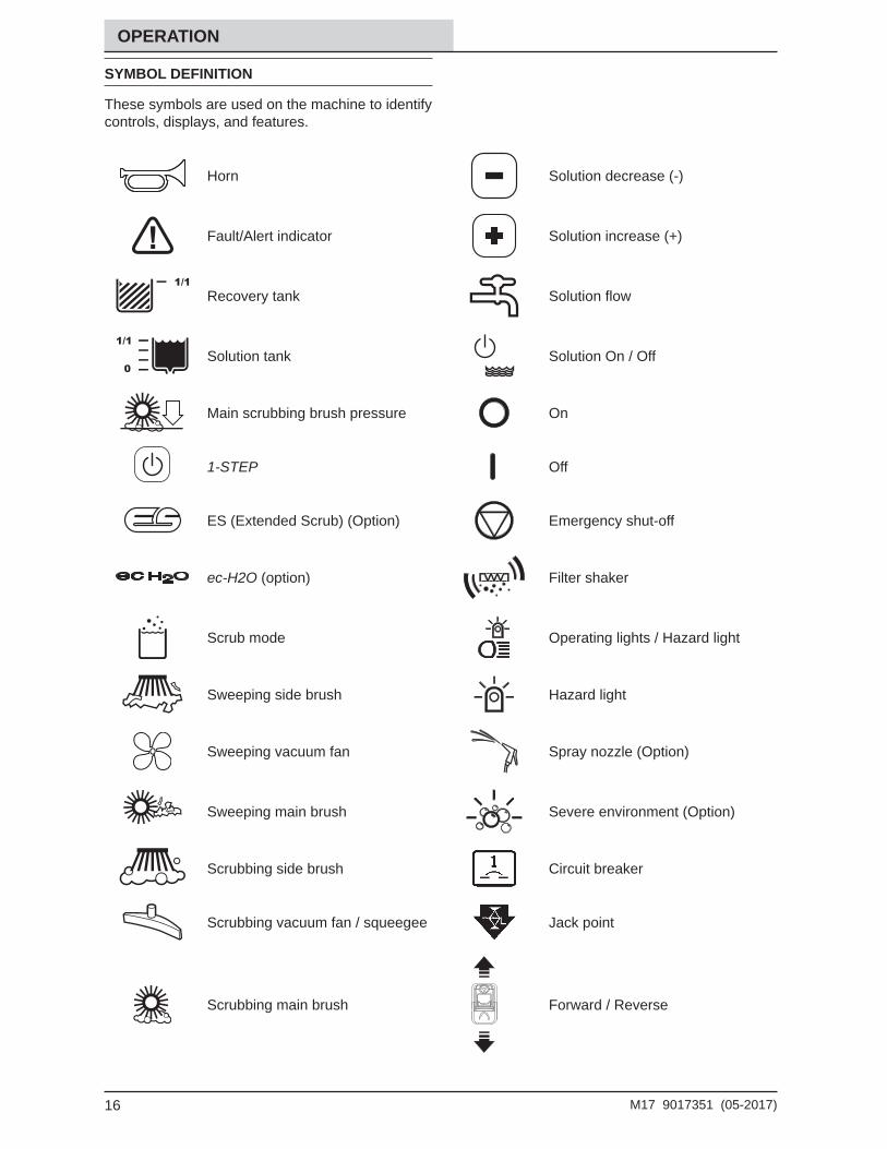
SYMBOL DEFINITION
These symbols are used on the machine to identify controls, displays, and features.
Horn Solution decrease (-)
Fault/Alert indicator Solution increase (+)
Recovery tank Solution fl ow
Solution tank Solution On / Off
Main scrubbing brush pressure On
1-STEP Off
ES (Extended Scrub) (Option) Emergency shut-off
ec-H2O (option) Filter shaker
Scrub mode Operating lights / Hazard light
Sweeping side brush Hazard light
Sweeping vacuum fan Spray nozzle (Option)
Sweeping main brush Severe environment (Option)
Scrubbing side brush Circuit breaker
Scrubbing vacuum fan / squeegee Jack point
Scrubbing main brush Forward / Reverse
17M17 9017351 (05-2017)
OPERATION
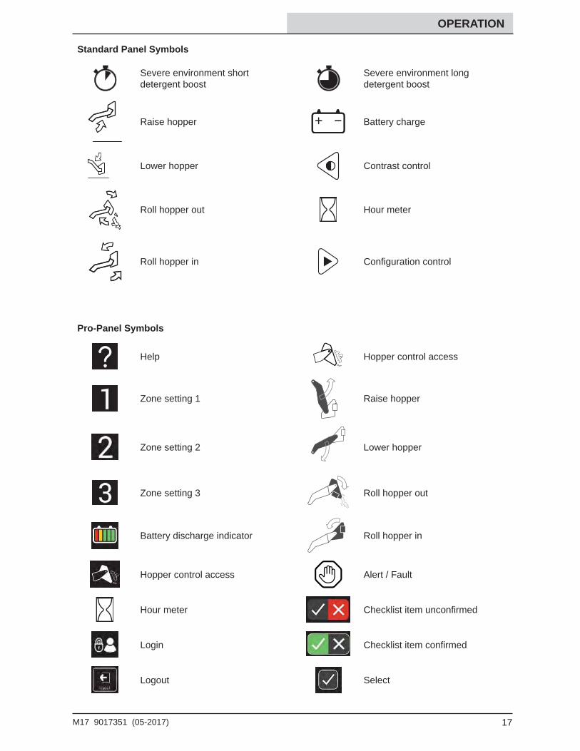
Standard Panel Symbols
Severe environment short detergent boost
Severe environment long detergent boost
Raise hopper Battery charge
Lower hopper Contrast control
Roll hopper out Hour meter
Roll hopper in Confi guration control
Pro-Panel Symbols
Help Hopper control access
Zone setting 1 Raise hopper
Zone setting 2 Lower hopper
Zone setting 3 Roll hopper out
Battery discharge indicator Roll hopper in
Hopper control access Alert / Fault
Hour meter Checklist item unconfi rmed
Login Checklist item confi rmed
Logout Select
18 M17 9017351 (05-2017)
OPERATION
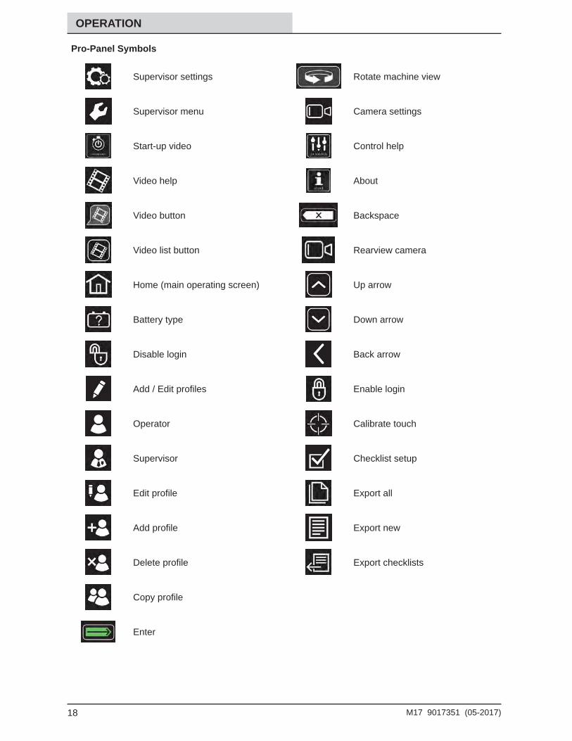
Pro-Panel Symbols
Supervisor settings Rotate machine view
Supervisor menu Camera settings
Start-up video Control help
Video help About
Video button Backspace
Video list button Rearview camera
Home (main operating screen) Up arrow
Battery type Down arrow
Disable login Back arrow
Add / Edit profi les Enable login
Operator Calibrate touch
Supervisor Checklist setup
Edit profi le Export all
Add profi le Export new
Delete profi le Export checklists
Copy profi le
Enter
19M17 9017351 (05-2017)
OPERATION
OPERATION OF CONTROLS - STANDARD PANEL
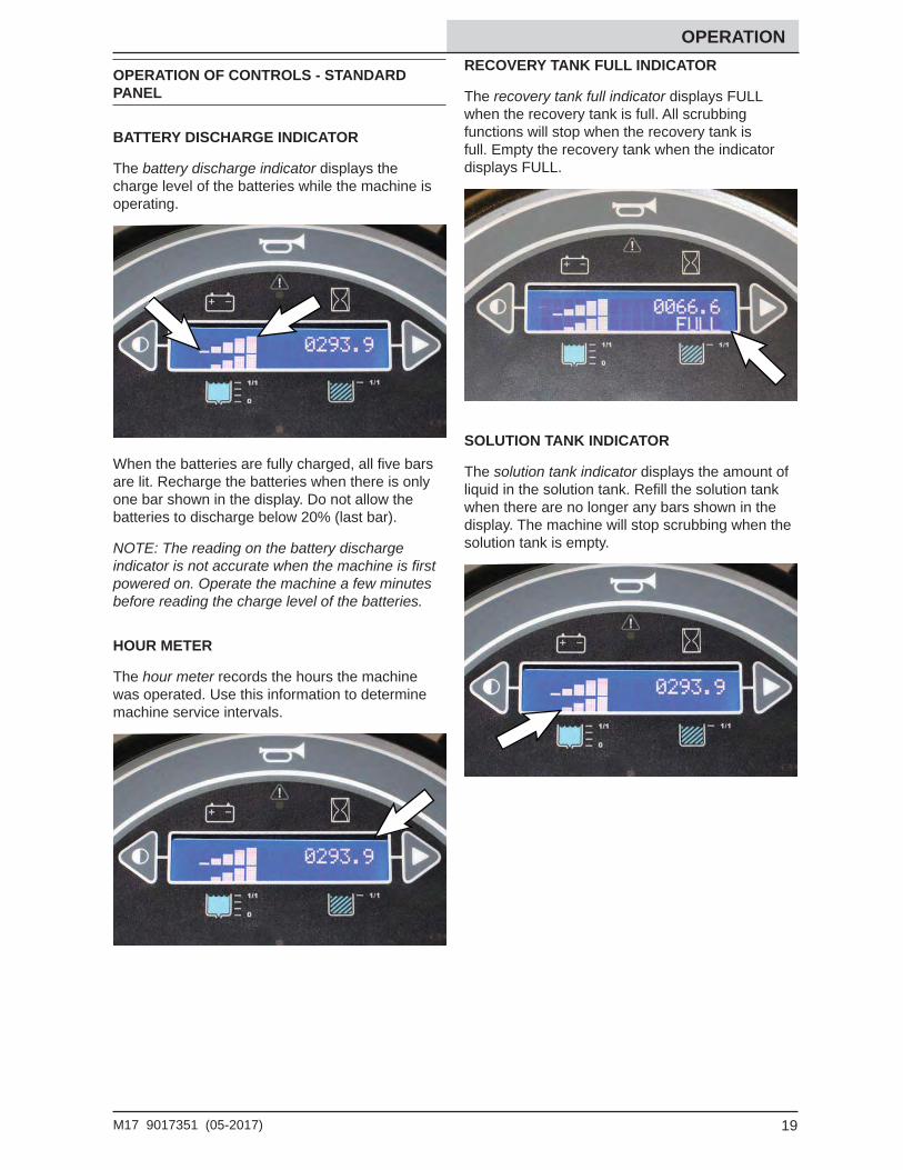
BATTERY DISCHARGE INDICATOR
The battery discharge indicator displays the charge level of the batteries while the machine is operating.
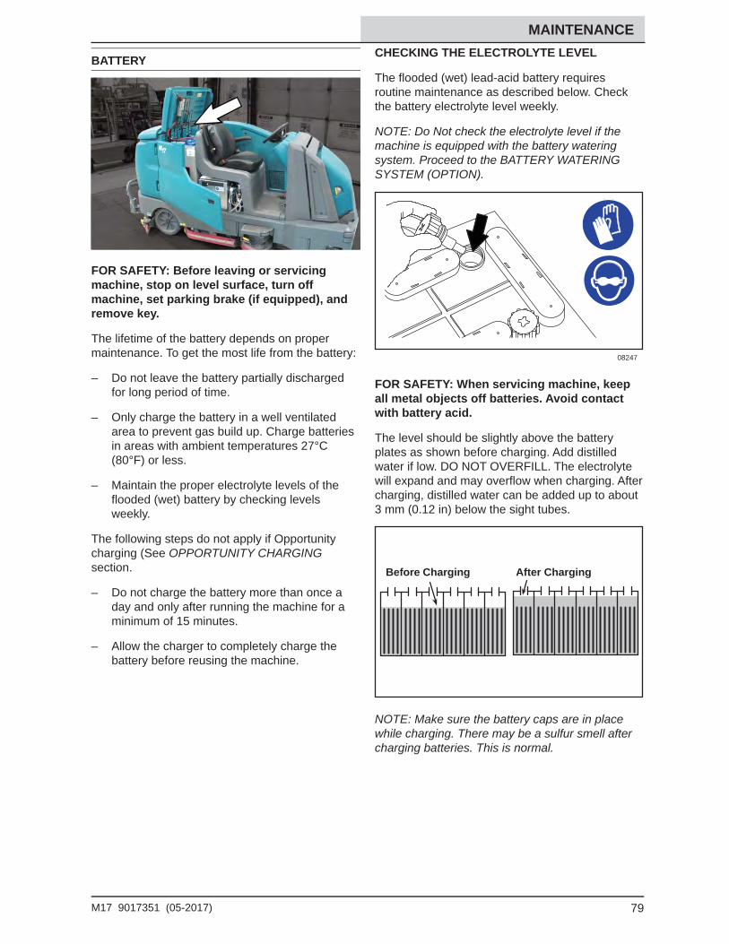
When the batteries are fully charged, all fi ve bars are lit. Recharge the batteries when there is only one bar shown in the display. Do not allow the batteries to discharge below 20% (last bar).
NOTE: The reading on the battery discharge indicator is not accurate when the machine is fi rst powered on. Operate the machine a few minutes before reading the charge level of the batteries.
HOUR METER
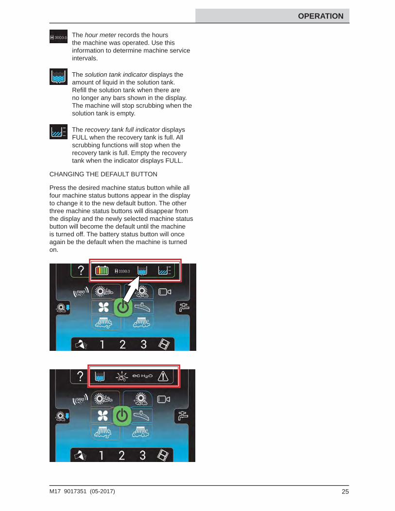
The hour meter records the hours the machine was operated. Use this information to determine machine service intervals.
RECOVERY TANK FULL INDICATOR
The recovery tank full indicator displays FULL when the recovery tank is full. All scrubbing functions will stop when the recovery tank is full. Empty the recovery tank when the indicator displays FULL.
SOLUTION TANK INDICATOR
The solution tank indicator displays the amount of liquid in the solution tank. Refi ll the solution tank when there are no longer any bars shown in the display. The machine will stop scrubbing when the solution tank is empty.
20 M17 9017351 (05-2017)
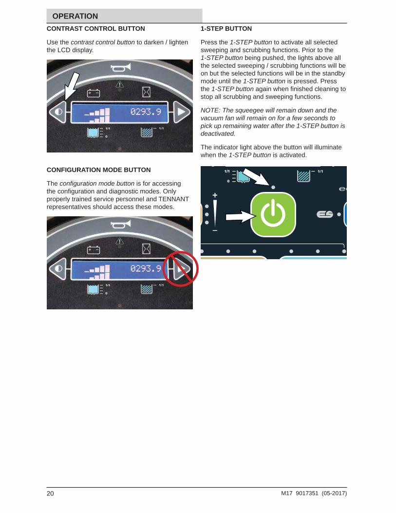
OPERATION CONTRAST CONTROL BUTTON
Use the contrast control button to darken / lighten the LCD display.
CONFIGURATION MODE BUTTON
The confi guration mode button is for accessing the confi guration and diagnostic modes. Only properly trained service personnel and TENNANT representatives should access these modes.
1-STEP BUTTON
Press the 1-STEP button to activate all selected sweeping and scrubbing functions. Prior to the 1-STEP button being pushed, the lights above all the selected sweeping / scrubbing functions will be on but the selected functions will be in the standby mode until the 1-STEP button is pressed. Press the 1-STEP button again when fi nished cleaning to stop all scrubbing and sweeping functions.
NOTE: The squeegee will remain down and the vacuum fan will remain on for a few seconds to pick up remaining water after the 1-STEP button is deactivated.
The indicator light above the button will illuminate when the 1-STEP button is activated.
21M17 9017351 (05-2017)
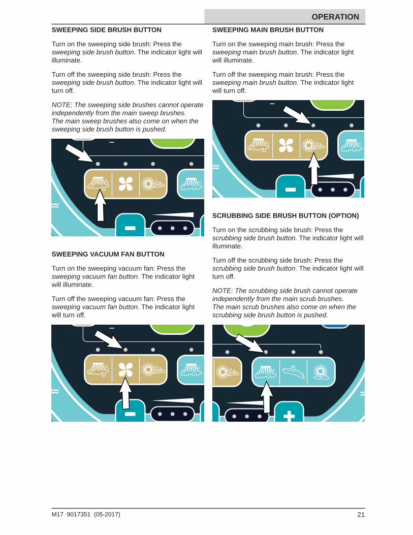
OPERATION SWEEPING SIDE BRUSH BUTTON
Turn on the sweeping side brush: Press the sweeping side brush button. The indicator light will illuminate.
Turn off the sweeping side brush: Press the sweeping side brush button. The indicator light will turn off.
NOTE: The sweeping side brushes cannot operate independently from the main sweep brushes. The main sweep brushes also come on when the sweeping side brush button is pushed.
SWEEPING VACUUM FAN BUTTON
Turn on the sweeping vacuum fan: Press the sweeping vacuum fan button. The indicator light will illuminate.
Turn off the sweeping vacuum fan: Press the sweeping vacuum fan button. The indicator light will turn off.
SWEEPING MAIN BRUSH BUTTON
Turn on the sweeping main brush: Press the sweeping main brush button. The indicator light will illuminate.
Turn off the sweeping main brush: Press the sweeping main brush button. The indicator light will turn off.
SCRUBBING SIDE BRUSH BUTTON (OPTION)
Turn on the scrubbing side brush: Press the scrubbing side brush button. The indicator light will illuminate.
Turn off the scrubbing side brush: Press the scrubbing side brush button. The indicator light will turn off.
NOTE: The scrubbing side brush cannot operate independently from the main scrub brushes. The main scrub brushes also come on when the scrubbing side brush button is pushed.
22 M17 9017351 (05-2017)
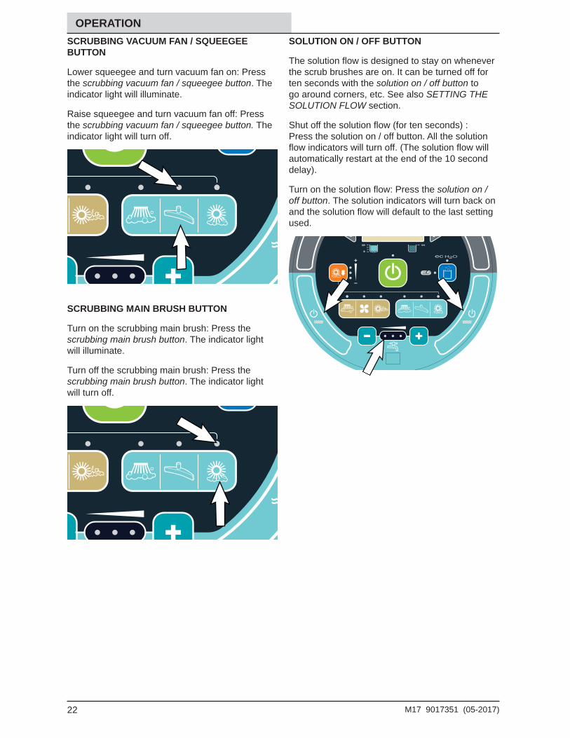
OPERATION SCRUBBING VACUUM FAN / SQUEEGEE BUTTON
Lower squeegee and turn vacuum fan on: Press the scrubbing vacuum fan / squeegee button. The indicator light will illuminate.
Raise squeegee and turn vacuum fan off: Press the scrubbing vacuum fan / squeegee button. The indicator light will turn off.
SCRUBBING MAIN BRUSH BUTTON
Turn on the scrubbing main brush: Press the scrubbing main brush button. The indicator light will illuminate.
Turn off the scrubbing main brush: Press the scrubbing main brush button. The indicator light will turn off.
SOLUTION ON / OFF BUTTON
The solution fl ow is designed to stay on whenever the scrub brushes are on. It can be turned off for ten seconds with the solution on / off button to go around corners, etc. See also SETTING THE SOLUTION FLOW section.
Shut off the solution fl ow (for ten seconds) : Press the solution on / off button. All the solution fl ow indicators will turn off. (The solution fl ow will automatically restart at the end of the 10 second delay).
Turn on the solution fl ow: Press the solution on / off button. The solution indicators will turn back on and the solution fl ow will default to the last setting used.
23M17 9017351 (05-2017)
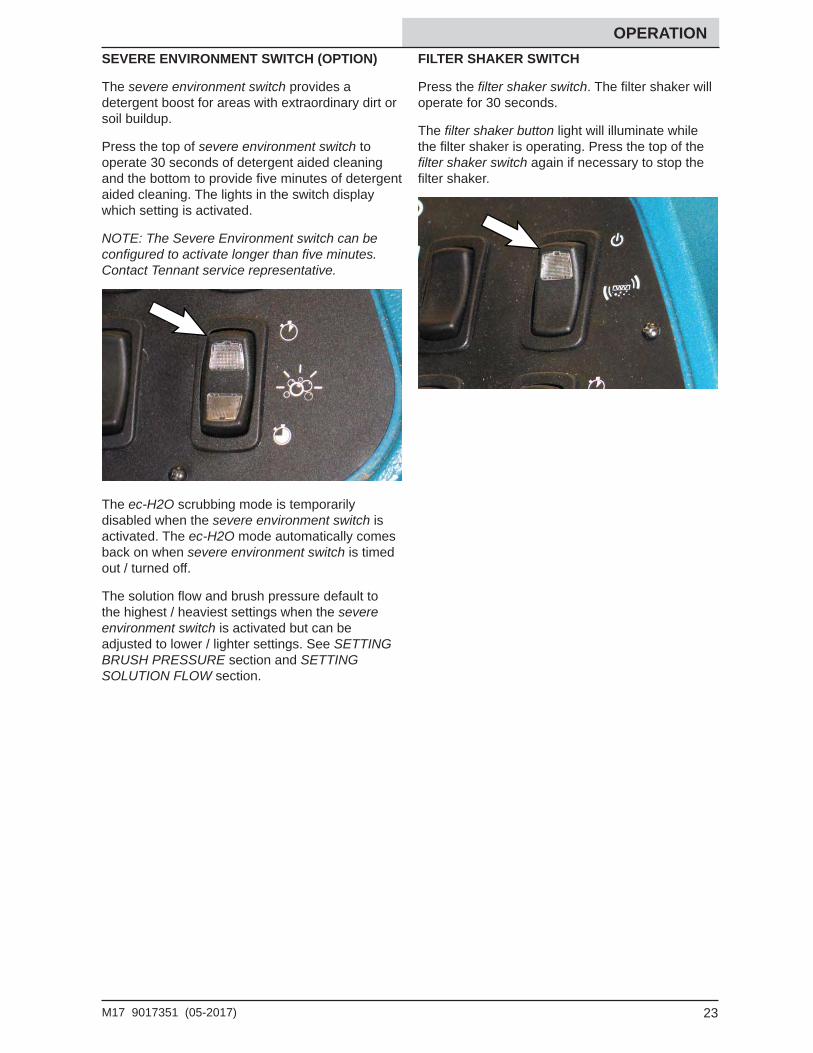
OPERATION SEVERE ENVIRONMENT SWITCH (OPTION)
The severe environment switch provides a detergent boost for areas with extraordinary dirt or soil buildup.
Press the top of severe environment switch to operate 30 seconds of detergent aided cleaning and the bottom to provide fi ve minutes of detergent aided cleaning. The lights in the switch display which setting is activated.
NOTE: The Severe Environment switch can be confi gured to activate longer than fi ve minutes. Contact Tennant service representative.
The ec-H2O scrubbing mode is temporarily disabled when the severe environment switch is activated. The ec-H2O mode automatically comes back on when severe environment switch is timed out / turned off.
The solution fl ow and brush pressure default to the highest / heaviest settings when the severe environment switch is activated but can be adjusted to lower / lighter settings. See SETTING BRUSH PRESSURE section and SETTING SOLUTION FLOW section.
FILTER SHAKER SWITCH
Press the fi lter shaker switch. The fi lter shaker will operate for 30 seconds.
The fi lter shaker button light will illuminate while the fi lter shaker is operating. Press the top of the fi lter shaker switch again if necessary to stop the fi lter shaker.
24 M17 9017351 (05-2017)
OPERATION
OPERATION OF CONTROLS - PRO-PANEL
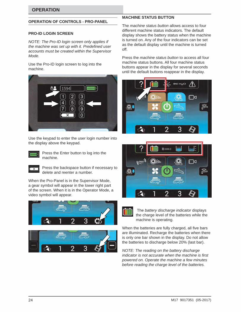
PRO-ID LOGIN SCREEN
NOTE: The Pro-ID login screen only applies if the machine was set up with it. Predefi ned user accounts must be created within the Supervisor Mode.
Use the Pro-ID login screen to log into the machine.
Use the keypad to enter the user login number into the display above the keypad.
Press the Enter button to log into the machine.
Press the backspace button if necessary to delete and reenter a number.
When the Pro-Panel is in the Supervisor Mode, a gear symbol will appear in the lower right part of the screen. When it is in the Operator Mode, a video symbol will appear.
MACHINE STATUS BUTTON
The machine status button allows access to four different machine status indicators. The default display shows the battery status when the machine is turned on. Any of the four indicators can be set as the default display until the machine is turned off.
Press the machine status button to access all four machine status buttons. All four machine status buttons appear in the display for several seconds until the default buttons reappear in the display.
The battery discharge indicator displays the charge level of the batteries while the machine is operating.
When the batteries are fully charged, all fi ve bars are illuminated. Recharge the batteries when there is only one bar shown in the display. Do not allow the batteries to discharge below 20% (last bar).
NOTE: The reading on the battery discharge indicator is not accurate when the machine is fi rst powered on. Operate the machine a few minutes before reading the charge level of the batteries.
25M17 9017351 (05-2017)
OPERATION
The hour meter records the hours the machine was operated. Use this information to determine machine service intervals.
The solution tank indicator displays the amount of liquid in the solution tank. Refi ll the solution tank when there are no longer any bars shown in the display. The machine will stop scrubbing when the solution tank is empty.
The recovery tank full indicator displays FULL when the recovery tank is full. All scrubbing functions will stop when the recovery tank is full. Empty the recovery tank when the indicator displays FULL.
CHANGING THE DEFAULT BUTTON
Press the desired machine status button while all four machine status buttons appear in the display to change it to the new default button. The other three machine status buttons will disappear from the display and the newly selected machine status button will become the default until the machine is turned off. The battery status button will once again be the default when the machine is turned on.
26 M17 9017351 (05-2017)
OPERATION 1-STEP BUTTON
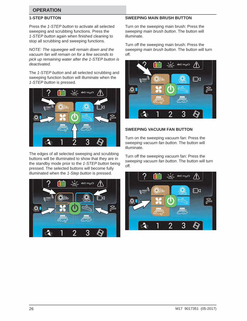
Press the 1-STEP button to activate all selected sweeping and scrubbing functions. Press the 1-STEP button again when fi nished cleaning to stop all scrubbing and sweeping functions.
NOTE: The squeegee will remain down and the vacuum fan will remain on for a few seconds to pick up remaining water after the 1-STEP button is deactivated.
The 1-STEP button and all selected scrubbing and sweeping function button will illuminate when the 1-STEP button is pressed.
The edges of all selected sweeping and scrubbing buttons will be illuminated to show that they are in the standby mode prior to the 1-STEP button being pressed. The selected buttons will become fully illuminated when the 1-Step button is pressed.
SWEEPING MAIN BRUSH BUTTON
Turn on the sweeping main brush: Press the sweeping main brush button. The button will illuminate.
Turn off the sweeping main brush: Press the sweeping main brush button. The button will turn off.
SWEEPING VACUUM FAN BUTTON
Turn on the sweeping vacuum fan: Press the sweeping vacuum fan button. The button will illuminate.
Turn off the sweeping vacuum fan: Press the sweeping vacuum fan button. The button will turn off.
27M17 9017351 (05-2017)
OPERATION SWEEPING SIDE BRUSH BUTTON
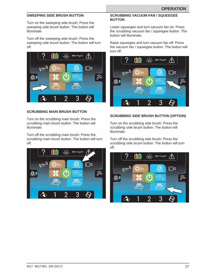
Turn on the sweeping side brush: Press the sweeping side brush button. The button will illuminate.
Turn off the sweeping side brush: Press the sweeping side brush button. The button will turn off.
SCRUBBING MAIN BRUSH BUTTON
Turn on the scrubbing main brush: Press the scrubbing main brush button. The button will illuminate.
Turn off the scrubbing main brush: Press the scrubbing main brush button. The button will turn off.
SCRUBBING VACUUM FAN / SQUEEGEE BUTTON
Lower squeegee and turn vacuum fan on: Press the scrubbing vacuum fan / squeegee button. The button will illuminate.
Raise squeegee and turn vacuum fan off: Press the vacuum fan / squeegee button. The button will turn off.
SCRUBBING SIDE BRUSH BUTTON (OPTION)
Turn on the scrubbing side brush: Press the scrubbing side brush button. The button will illuminate.
Turn off the scrubbing side brush: Press the scrubbing side brush button. The button will turn off.
28 M17 9017351 (05-2017)
OPERATION SOLUTION ON / OFF BUTTON
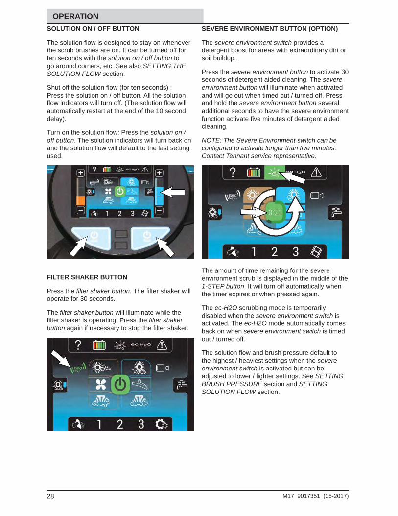
The solution fl ow is designed to stay on whenever the scrub brushes are on. It can be turned off for ten seconds with the solution on / off button to go around corners, etc. See also SETTING THE SOLUTION FLOW section.
Shut off the solution fl ow (for ten seconds) : Press the solution on / off button. All the solution fl ow indicators will turn off. (The solution fl ow will automatically restart at the end of the 10 second delay).
Turn on the solution fl ow: Press the solution on / off button. The solution indicators will turn back on and the solution fl ow will default to the last setting used.
FILTER SHAKER BUTTON
Press the fi lter shaker button. The fi lter shaker will operate for 30 seconds.
The fi lter shaker button will illuminate while the fi lter shaker is operating. Press the fi lter shaker button again if necessary to stop the fi lter shaker.
SEVERE ENVIRONMENT BUTTON (OPTION)
The severe environment switch provides a detergent boost for areas with extraordinary dirt or soil buildup.
Press the severe environment button to activate 30 seconds of detergent aided cleaning. The severe environment button will illuminate when activated and will go out when timed out / turned off. Press and hold the severe environment button several additional seconds to have the severe environment function activate fi ve minutes of detergent aided cleaning.
NOTE: The Severe Environment switch can be confi gured to activate longer than fi ve minutes. Contact Tennant service representative.
The amount of time remaining for the severe environment scrub is displayed in the middle of the 1-STEP button. It will turn off automatically when the timer expires or when pressed again.
The ec-H2O scrubbing mode is temporarily disabled when the severe environment switch is activated. The ec-H2O mode automatically comes back on when severe environment switch is timed out / turned off.
The solution fl ow and brush pressure default to the highest / heaviest settings when the severe environment switch is activated but can be adjusted to lower / lighter settings. See SETTING BRUSH PRESSURE section and SETTING SOLUTION FLOW section.
29M17 9017351 (05-2017)
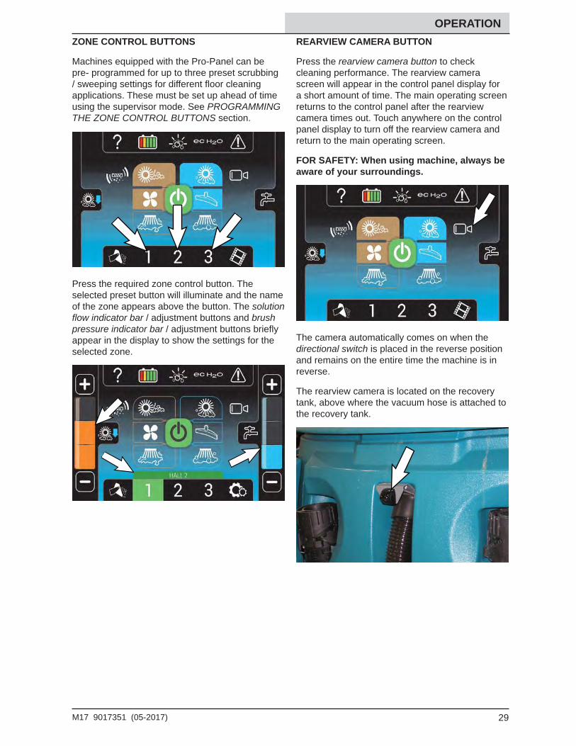
OPERATION ZONE CONTROL BUTTONS
Machines equipped with the Pro-Panel can be pre- programmed for up to three preset scrubbing / sweeping settings for different fl oor cleaning applications. These must be set up ahead of time using the supervisor mode. See PROGRAMMING THE ZONE CONTROL BUTTONS section.
Press the required zone control button. The selected preset button will illuminate and the name of the zone appears above the button. The solution fl ow indicator bar / adjustment buttons and brush pressure indicator bar / adjustment buttons briefl y appear in the display to show the settings for the selected zone.
REARVIEW CAMERA BUTTON
Press the rearview camera button to check cleaning performance. The rearview camera screen will appear in the control panel display for a short amount of time. The main operating screen returns to the control panel after the rearview camera times out. Touch anywhere on the control panel display to turn off the rearview camera and return to the main operating screen.
FOR SAFETY: When using machine, always be aware of your surroundings.
The camera automatically comes on when the directional switch is placed in the reverse position and remains on the entire time the machine is in reverse.
The rearview camera is located on the recovery tank, above where the vacuum hose is attached to the recovery tank.
30 M17 9017351 (05-2017)
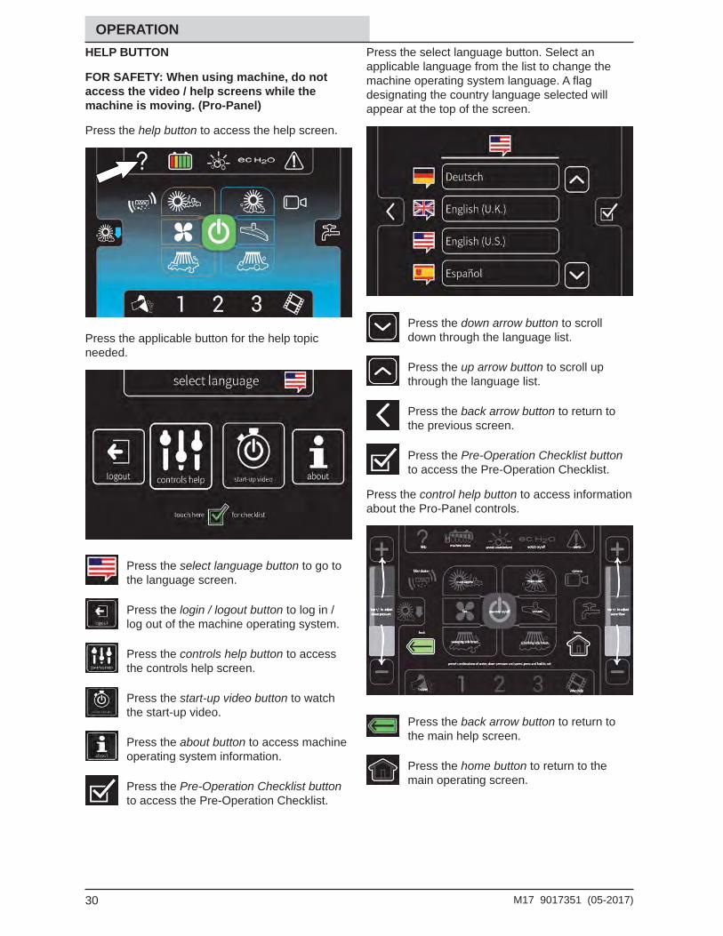
OPERATION HELP BUTTON
FOR SAFETY: When using machine, do not access the video / help screens while the machine is moving. (Pro-Panel)
Press the help button to access the help screen.
Press the applicable button for the help topic needed.
Press the select language button to go to the language screen.
Press the login / logout button to log in / log out of the machine operating system.
Press the controls help button to access the controls help screen.
Press the start-up video button to watch the start-up video.
Press the about button to access machine operating system information.
Press the Pre-Operation Checklist button to access the Pre-Operation Checklist.
Press the select language button. Select an applicable language from the list to change the machine operating system language. A fl ag designating the country language selected will appear at the top of the screen.
Press the down arrow button to scroll down through the language list.
Press the up arrow button to scroll up through the language list.
Press the back arrow button to return to the previous screen.
Press the Pre-Operation Checklist button to access the Pre-Operation Checklist.
Press the control help button to access information about the Pro-Panel controls.
Press the back arrow button to return to the main help screen.
Press the home button to return to the main operating screen.
31M17 9017351 (05-2017)
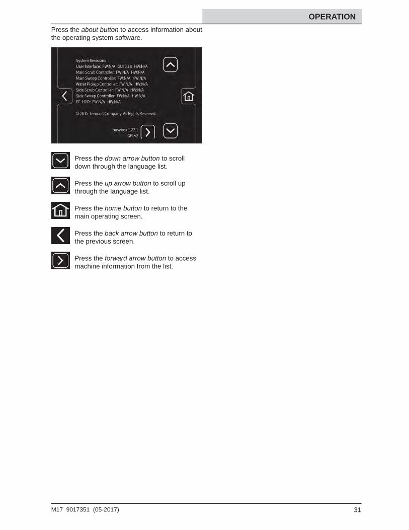
OPERATION Press the about button to access information about the operating system software.
Press the down arrow button to scroll down through the language list.
Press the up arrow button to scroll up through the language list.
Press the home button to return to the main operating screen.
Press the back arrow button to return to the previous screen.
Press the forward arrow button to access machine information from the list.
32 M17 9017351 (05-2017)
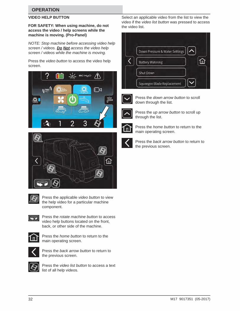
OPERATION VIDEO HELP BUTTON
FOR SAFETY: When using machine, do not access the video / help screens while the machine is moving. (Pro-Panel)
NOTE: Stop machine before accessing video help screen / videos. Do Not access the video help screen / videos while the machine is moving.
Press the video button to access the video help screen.
Press the applicable video button to view the help video for a particular machine component.
Press the rotate machine button to access video help buttons located on the front, back, or other side of the machine.
Press the home button to return to the main operating screen.
Press the back arrow button to return to the previous screen.
Press the video list button to access a text list of all help videos.
Select an applicable video from the list to view the video if the video list button was pressed to access the video list.
Press the down arrow button to scroll down through the list.
Press the up arrow button to scroll up through the list.
Press the home button to return to the main operating screen.
Press the back arrow button to return to the previous screen.
33M17 9017351 (05-2017)
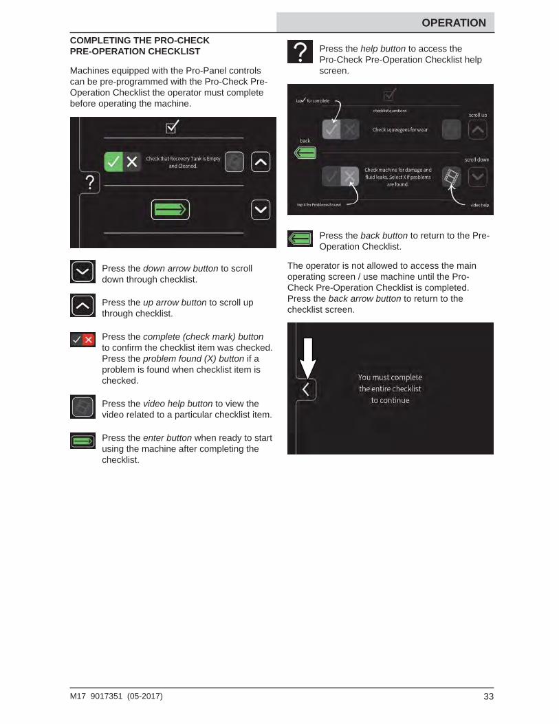
OPERATION COMPLETING THE PRO-CHECK PRE-OPERATION CHECKLIST
Machines equipped with the Pro-Panel controls can be pre-programmed with the Pro-Check Pre-Operation Checklist the operator must complete before operating the machine.
Press the down arrow button to scroll down through checklist.
Press the up arrow button to scroll up through checklist.
Press the complete (check mark) button to confi rm the checklist item was checked. Press the problem found (X) button if a problem is found when checklist item is checked.
Press the video help button to view the video related to a particular checklist item.
Press the enter button when ready to start using the machine after completing the checklist.
Press the help button to access the Pro-Check Pre-Operation Checklist help screen.
Press the back button to return to the Pre-Operation Checklist.
The operator is not allowed to access the main operating screen / use machine until the Pro-Check Pre-Operation Checklist is completed. Press the back arrow button to return to the checklist screen.
34 M17 9017351 (05-2017)
OPERATION
OPERATION OF CONTROLS - ALL MACHINES
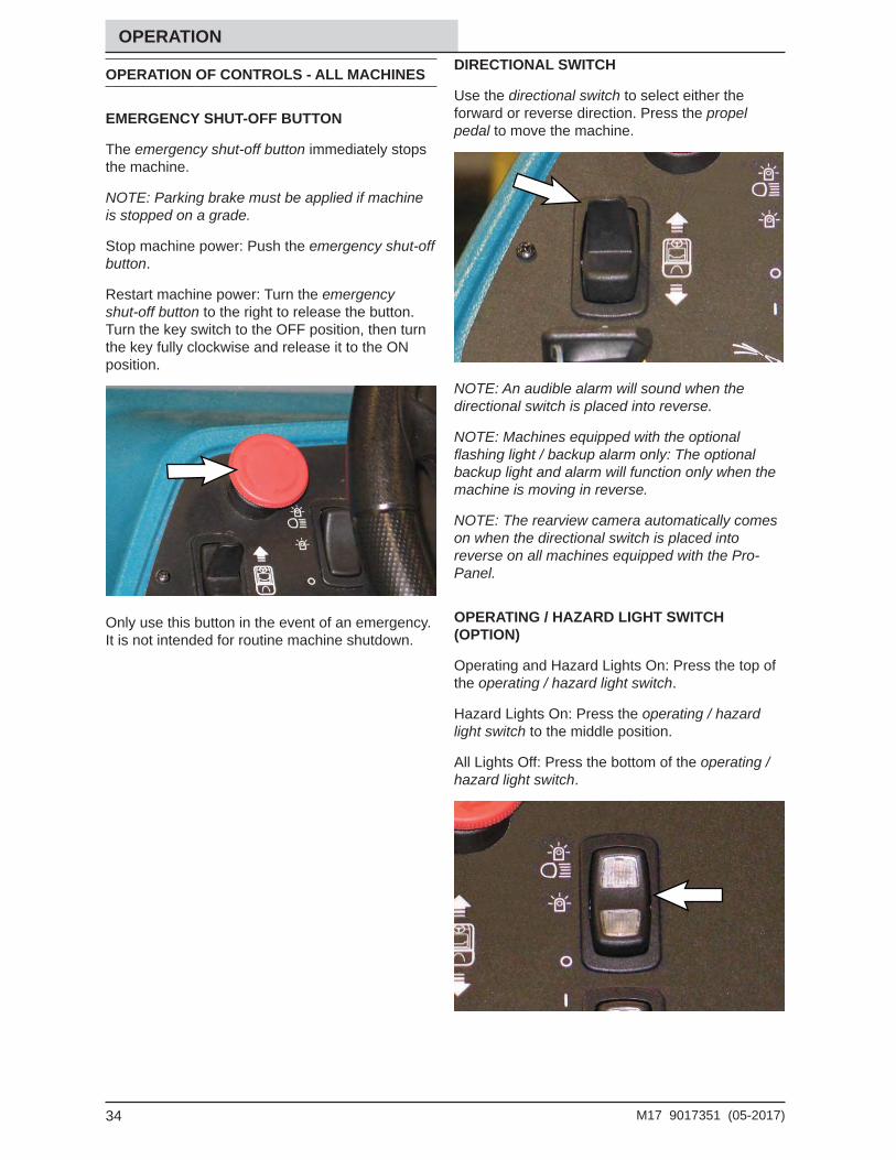
EMERGENCY SHUT-OFF BUTTON
The emergency shut-off button immediately stops the machine.
NOTE: Parking brake must be applied if machine is stopped on a grade.
Stop machine power: Push the emergency shut-off button.
Restart machine power: Turn the emergency shut-off button to the right to release the button. Turn the key switch to the OFF position, then turn the key fully clockwise and release it to the ON position.
Only use this button in the event of an emergency. It is not intended for routine machine shutdown.
DIRECTIONAL SWITCH
Use the directional switch to select either the forward or reverse direction. Press the propel pedal to move the machine.
NOTE: An audible alarm will sound when the directional switch is placed into reverse.
NOTE: Machines equipped with the optional fl ashing light / backup alarm only: The optional backup light and alarm will function only when the machine is moving in reverse.
NOTE: The rearview camera automatically comes on when the directional switch is placed into reverse on all machines equipped with the Pro-Panel.
OPERATING / HAZARD LIGHT SWITCH (OPTION)
Operating and Hazard Lights On: Press the top of the operating / hazard light switch.
Hazard Lights On: Press the operating / hazard light switch to the middle position.
All Lights Off: Press the bottom of the operating / hazard light switch.
35M17 9017351 (05-2017)
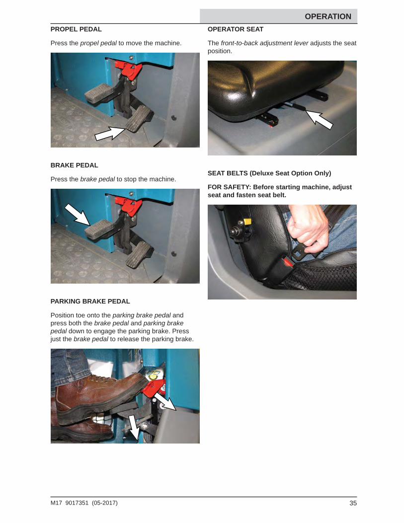
OPERATION PROPEL PEDAL
Press the propel pedal to move the machine.
BRAKE PEDAL
Press the brake pedal to stop the machine.
PARKING BRAKE PEDAL
Position toe onto the parking brake pedal and press both the brake pedal and parking brake pedal down to engage the parking brake. Press just the brake pedal to release the parking brake.
OPERATOR SEAT
The front-to-back adjustment lever adjusts the seat position.
SEAT BELTS (Deluxe Seat Option Only)
FOR SAFETY: Before starting machine, adjust seat and fasten seat belt.
36 M17 9017351 (05-2017)
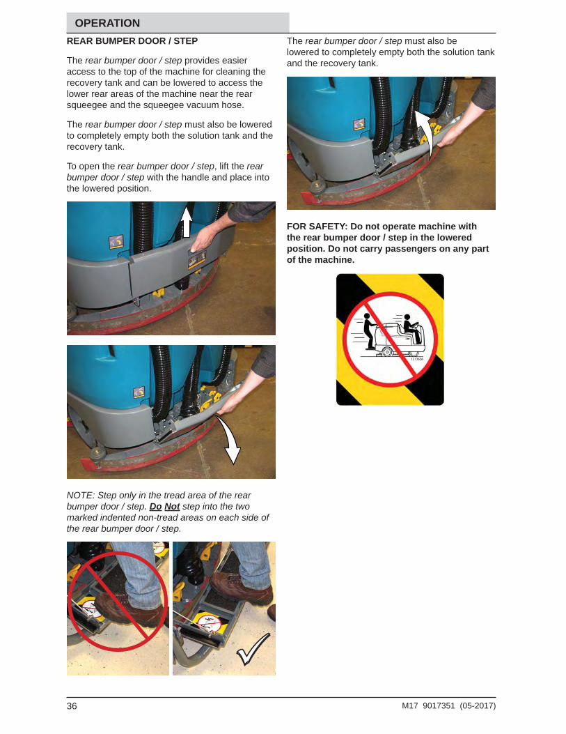
OPERATION REAR BUMPER DOOR / STEP
The rear bumper door / step provides easier access to the top of the machine for cleaning the recovery tank and can be lowered to access the lower rear areas of the machine near the rear squeegee and the squeegee vacuum hose.
The rear bumper door / step must also be lowered to completely empty both the solution tank and the recovery tank.
To open the rear bumper door / step, lift the rear bumper door / step with the handle and place into the lowered position.
NOTE: Step only in the tread area of the rear bumper door / step. Do Not step into the two marked indented non-tread areas on each side of the rear bumper door / step.
The rear bumper door / step must also be lowered to completely empty both the solution tank and the recovery tank.
FOR SAFETY: Do not operate machine with the rear bumper door / step in the lowered position. Do not carry passengers on any part of the machine.
37M17 9017351 (05-2017)
OPERATION
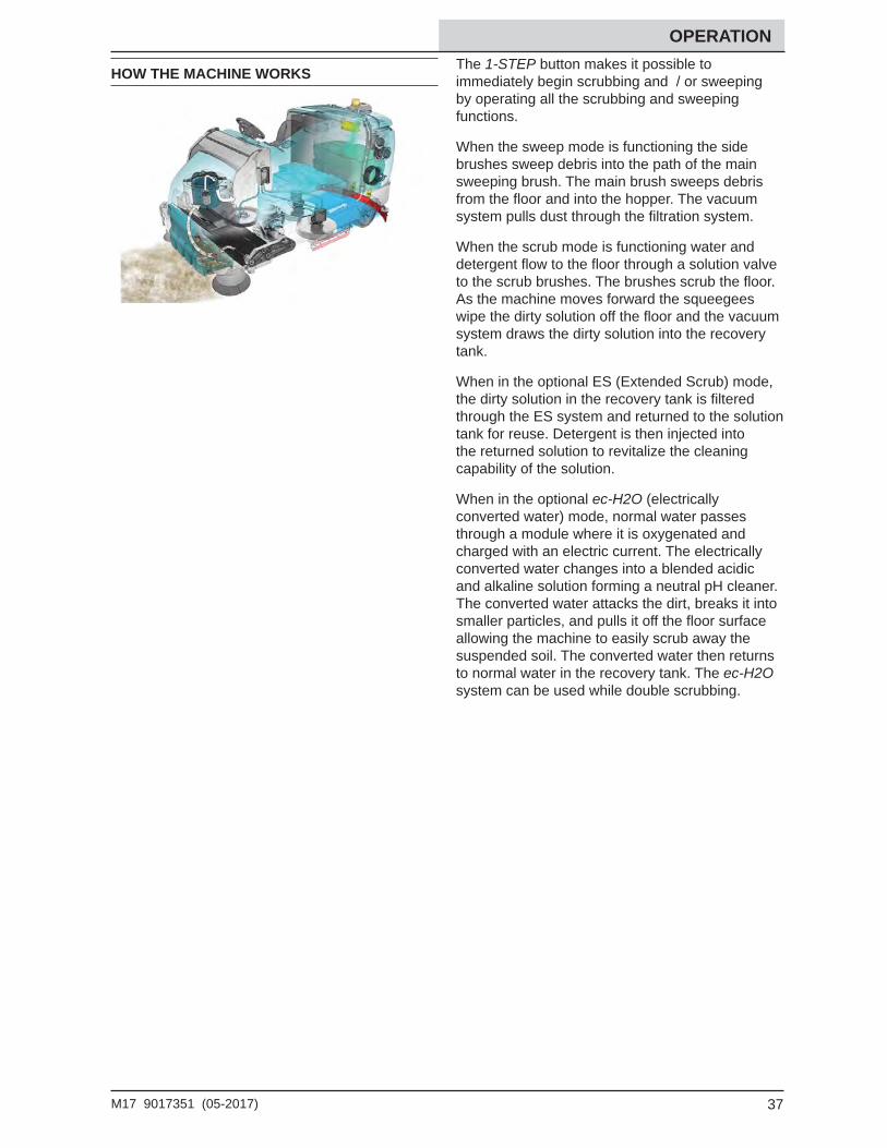
HOW THE MACHINE WORKS The 1-STEP button makes it possible to immediately begin scrubbing and / or sweeping by operating all the scrubbing and sweeping functions.
When the sweep mode is functioning the side brushes sweep debris into the path of the main sweeping brush. The main brush sweeps debris from the fl oor and into the hopper. The vacuum system pulls dust through the fi ltration system.
When the scrub mode is functioning water and detergent fl ow to the fl oor through a solution valve to the scrub brushes. The brushes scrub the fl oor. As the machine moves forward the squeegees wipe the dirty solution off the fl oor and the vacuum system draws the dirty solution into the recovery tank.
When in the optional ES (Extended Scrub) mode, the dirty solution in the recovery tank is fi ltered through the ES system and returned to the solution tank for reuse. Detergent is then injected into the returned solution to revitalize the cleaning capability of the solution.
When in the optional ec-H2O (electrically converted water) mode, normal water passes through a module where it is oxygenated and charged with an electric current. The electrically converted water changes into a blended acidic and alkaline solution forming a neutral pH cleaner. The converted water attacks the dirt, breaks it into smaller particles, and pulls it off the fl oor surface allowing the machine to easily scrub away the suspended soil. The converted water then returns to normal water in the recovery tank. The ec-H2O system can be used while double scrubbing.
38 M17 9017351 (05-2017)
OPERATION
BRUSH AND PAD INFORMATION
For best results, use the appropriate brush or pad for the cleaning application. Listed below are brushes and pads and the applications for which each is best suited.
NOTE: The amount and type of soilage play an important role in determining the type of brush or pad to use. Contact a Tennant representative for specifi c recommendations.
Nylon brush (Cylindrical and Disk)* - Softer nylon bristles are recommended for scrubbing coated fl oors. Cleans without scuffi ng.
Heavy Duty Polypropylene brush (Disk) - Heavy duty polypropylene bristles provide a more aggressive cleaning performance and can more easily lift compacted dirt, debris, and sand while offering excellent scrubbing performance.
Polypropylene brush (Cylindrical and Disk)* - General purpose polypropylene bristles lift lightly compacted dirt without scuffi ng high-gloss coated fl oors.
Super AB brush (Cylindrical and Disk)* - Nylon fi ber with an abrasive grit to remove stains and compacted dirt. Aggressive action on any surface. Performs well on buildup, grease, or tire marks.
* This brush is also available for the side brush.
Polypropylene Sand Wedge Main Brush − For sweeping heavy accumulations of sand and other small particulates.
Stripping pad (Brown) - For stripping of fl oor fi nish to prepare the fl oor for recoating.
Scrubbing pad (Blue) − For medium to heavy duty scrubbing. Removes dirt, spills, and scuffs.
Buffi ng pad (Red) - For light duty scrubbing without removing fl oor fi nish.
Polishing pad (White) - For maintaining highly polished or burnished fl oors.
Polypropylene Side Brush − For general sweeping of light to medium debris.
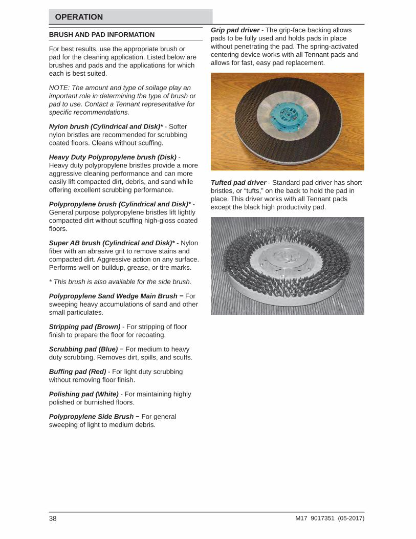
Grip pad driver - The grip-face backing allows pads to be fully used and holds pads in place without penetrating the pad. The spring-activated centering device works with all Tennant pads and allows for fast, easy pad replacement.
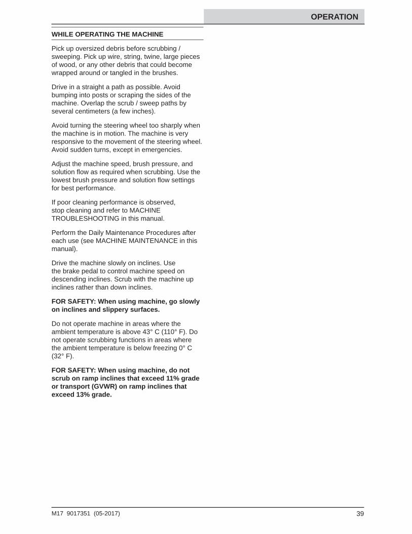
Tufted pad driver - Standard pad driver has short bristles, or “tufts,” on the back to hold the pad in place. This driver works with all Tennant pads except the black high productivity pad.
39M17 9017351 (05-2017)
OPERATION
WHILE OPERATING THE MACHINE
Pick up oversized debris before scrubbing / sweeping. Pick up wire, string, twine, large pieces of wood, or any other debris that could become wrapped around or tangled in the brushes.
Drive in a straight a path as possible. Avoid bumping into posts or scraping the sides of the machine. Overlap the scrub / sweep paths by several centimeters (a few inches).
Avoid turning the steering wheel too sharply when the machine is in motion. The machine is very responsive to the movement of the steering wheel. Avoid sudden turns, except in emergencies.
Adjust the machine speed, brush pressure, and solution fl ow as required when scrubbing. Use the lowest brush pressure and solution fl ow settings for best performance.
If poor cleaning performance is observed, stop cleaning and refer to MACHINE TROUBLESHOOTING in this manual.
Perform the Daily Maintenance Procedures after each use (see MACHINE MAINTENANCE in this manual).
Drive the machine slowly on inclines. Use the brake pedal to control machine speed on descending inclines. Scrub with the machine up inclines rather than down inclines.
FOR SAFETY: When using machine, go slowly on inclines and slippery surfaces.
Do not operate machine in areas where the ambient temperature is above 43° C (110° F). Do not operate scrubbing functions in areas where the ambient temperature is below freezing 0° C (32° F).
FOR SAFETY: When using machine, do not scrub on ramp inclines that exceed 11% grade or transport (GVWR) on ramp inclines that exceed 13% grade.
40 M17 9017351 (05-2017)
OPERATION
PRE-OPERATION CHECKLIST
Perform the following steps before operating the machine:
Check for fl uid leaks.
Check the hydraulic fl uid level.
Check the condition of the hopper dust fi lter and seals.
Clean the hopper and the debris screen.
Check left side squeegee for wear and damage.
Check main brushes for wear and damage. Remove wire, string, or twine wrapped around the main scrub brushes.
Machines equipped with cylindrical brushes: Confi rm the debris trough is empty and clean.
Machines equipped with side brush option: Check for wire, string, or twine wrapped around the scrub brush.
Machines equipped with scrubbing side brush option: Check squeegee for wear and damage.
Check the rear squeegees for wear and damage.
Check the recovery tank cover seal for wear or damage.
Confi rm the vacuum fan inlet fi lter is clean.
Machines equipped with ES option: Drain and clean the solution tank, fl oat sensor, and ES fi lter
Machines equipped with ES option: Ensure ES fi lter at bottom of recovery tank is clean.
Check the right side squeegee for wear and damage.
Check the solution tank cover seal for wear or damage.
ec-H2O Scrubbing: Confi rm all conventional cleaning agents/restorers are drained and rinsed from the solution tank.
ec-H2O Scrubbing: Confi rm the solution tank is fi lled with clear cool water only.
Check the horn, headlights, taillights, safety lights, and backup alarm (if equipped).
Check the brakes and steering for proper operation.
Check parking brake pedal for proper operation.
Check the tires for damage.
Check maintenance records to determine maintenance requirements.
41M17 9017351 (05-2017)
OPERATION
STARTING THE MACHINE
FOR SAFETY: Before starting machine, adjust seat and fasten seat belt (if equipped).
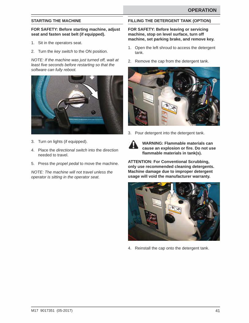
1. Sit in the operators seat.
2. Turn the key switch to the ON position.
NOTE: If the machine was just turned off, wait at least fi ve seconds before restarting so that the software can fully reboot.
3. Turn on lights (if equipped).
4. Place the directional switch into the direction needed to travel.
5. Press the propel pedal to move the machine.
NOTE: The machine will not travel unless the operator is sitting in the operator seat.
FILLING THE DETERGENT TANK (OPTION)
FOR SAFETY: Before leaving or servicing machine, stop on level surface, turn off machine, set parking brake, and remove key.
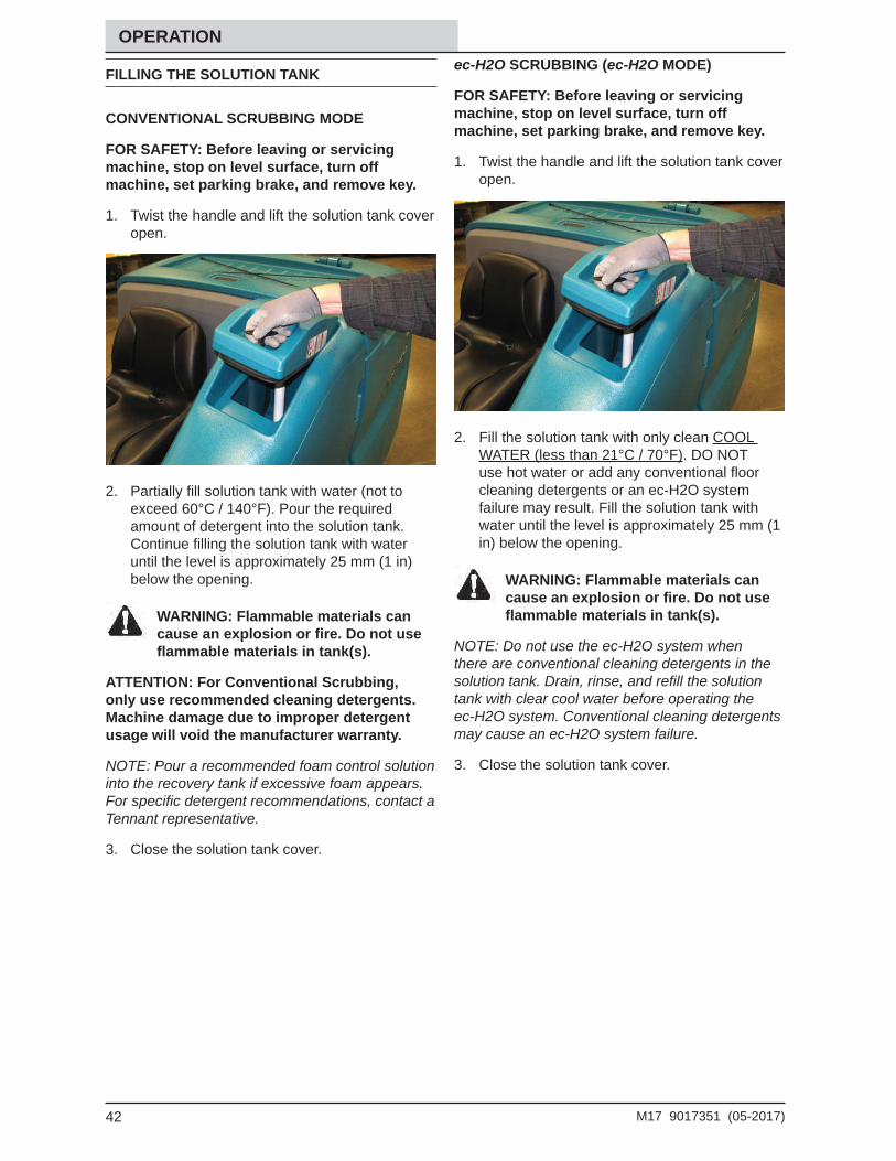
1. Open the left shroud to access the detergent tank.
2. Remove the cap from the detergent tank.
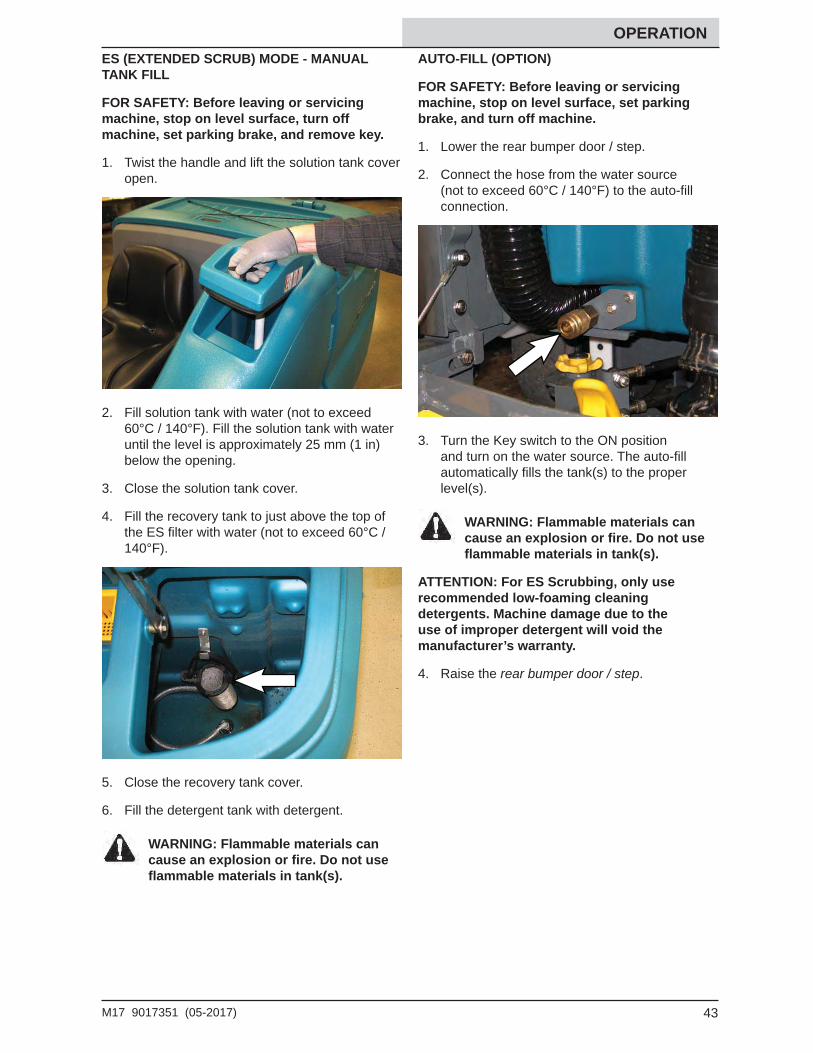
3. Pour detergent into the detergent tank.
WARNING: Flammable materials can cause an explosion or fi re. Do not use fl ammable materials in tank(s).
ATTENTION: For Conventional Scrubbing, only use recommended cleaning detergents. Machine damage due to improper detergent usage will void the manufacturer warranty.
4. Reinstall the cap onto the detergent tank.
42 M17 9017351 (05-2017)
OPERATION
FILLING THE SOLUTION TANK
CONVENTIONAL SCRUBBING MODE
FOR SAFETY: Before leaving or servicing machine, stop on level surface, turn off machine, set parking brake, and remove key.
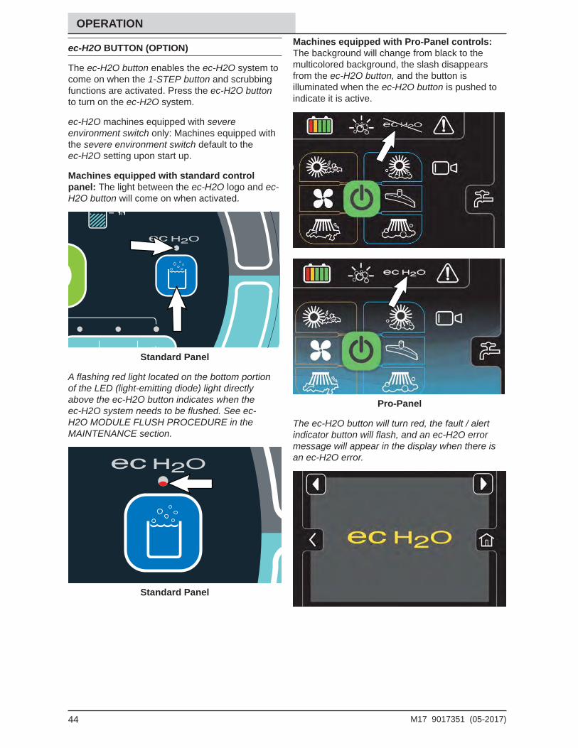
1. Twist the handle and lift the solution tank cover open.
2. Partially fi ll solution tank with water (not to exceed 60°C / 140°F). Pour the required amount of detergent into the solution tank. Continue fi lling the solution tank with water until the level is approximately 25 mm (1 in) below the opening.
WARNING: Flammable materials can cause an explosion or fi re. Do not use fl ammable materials in tank(s).
ATTENTION: For Conventional Scrubbing, only use recommended cleaning detergents. Machine damage due to improper detergent usage will void the manufacturer warranty.
NOTE: Pour a recommended foam control solution into the recovery tank if excessive foam appears. For specifi c detergent recommendations, contact a Tennant representative.
3. Close the solution tank cover.
ec-H2O SCRUBBING (ec-H2O MODE)
FOR SAFETY: Before leaving or servicing machine, stop on level surface, turn off machine, set parking brake, and remove key.
1. Twist the handle and lift the solution tank cover open.
2. Fill the solution tank with only clean COOL WATER (less than 21°C / 70°F). DO NOT use hot water or add any conventional fl oor cleaning detergents or an ec-H2O system failure may result. Fill the solution tank with water until the level is approximately 25 mm (1 in) below the opening.
WARNING: Flammable materials can cause an explosion or fi re. Do not use fl ammable materials in tank(s).
NOTE: Do not use the ec-H2O system when there are conventional cleaning detergents in the solution tank. Drain, rinse, and refi ll the solution tank with clear cool water before operating the ec-H2O system. Conventional cleaning detergents may cause an ec-H2O system failure.
3. Close the solution tank cover.
43M17 9017351 (05-2017)
OPERATION ES (EXTENDED SCRUB) MODE - MANUAL TANK FILL
FOR SAFETY: Before leaving or servicing machine, stop on level surface, turn off machine, set parking brake, and remove key.
1. Twist the handle and lift the solution tank cover open.
2. Fill solution tank with water (not to exceed 60°C / 140°F). Fill the solution tank with water until the level is approximately 25 mm (1 in) below the opening.
3. Close the solution tank cover.
4. Fill the recovery tank to just above the top of the ES fi lter with water (not to exceed 60°C / 140°F).
5. Close the recovery tank cover.
6. Fill the detergent tank with detergent.
WARNING: Flammable materials can cause an explosion or fi re. Do not use fl ammable materials in tank(s).
AUTO-FILL (OPTION)
FOR SAFETY: Before leaving or servicing machine, stop on level surface, set parking brake, and turn off machine.
1. Lower the rear bumper door / step.
2. Connect the hose from the water source (not to exceed 60°C / 140°F) to the auto-fi ll connection.
3. Turn the Key switch to the ON position and turn on the water source. The auto-fi ll automatically fi lls the tank(s) to the proper level(s).
WARNING: Flammable materials can cause an explosion or fi re. Do not use fl ammable materials in tank(s).
ATTENTION: For ES Scrubbing, only use recommended low-foaming cleaning detergents. Machine damage due to the use of improper detergent will void the manufacturer’s warranty.
4. Raise the rear bumper door / step.
44 M17 9017351 (05-2017)
OPERATION
ec-H2O BUTTON (OPTION)
The ec-H2O button enables the ec-H2O system to come on when the 1-STEP button and scrubbing functions are activated. Press the ec-H2O button to turn on the ec-H2O system.
ec-H2O machines equipped with severe environment switch only: Machines equipped with the severe environment switch default to the ec-H2O setting upon start up.
Machines equipped with standard control panel: The light between the ec-H2O logo and ec-H2O button will come on when activated.
Standard Panel
A fl ashing red light located on the bottom portion of the LED (light-emitting diode) light directly above the ec-H2O button indicates when the ec-H2O system needs to be fl ushed. See ec-H2O MODULE FLUSH PROCEDURE in the MAINTENANCE section.
Standard Panel
Machines equipped with Pro-Panel controls: The background will change from black to the multicolored background, the slash disappears from the ec-H2O button, and the button is illuminated when the ec-H2O button is pushed to indicate it is active.
Pro-Panel
The ec-H2O button will turn red, the fault / alert indicator button will fl ash, and an ec-H2O error message will appear in the display when there is an ec-H2O error.
45M17 9017351 (05-2017)
OPERATION
ES (EXTENDED SCRUB) BUTTON (OPTION)
The ES button enables the ES system to come on when the 1-STEP button is activated.
Machines equipped with standard control panel: The light between the ES logo and ES button will come on when the ES button is pushed.
Standard Panel
Machines equipped with Pro-Panel controls: The slash disappears from the ES button and the button is illuminated when the ES button is pushed to indicate it is active.
Pro-Panel
46 M17 9017351 (05-2017)
OPERATION
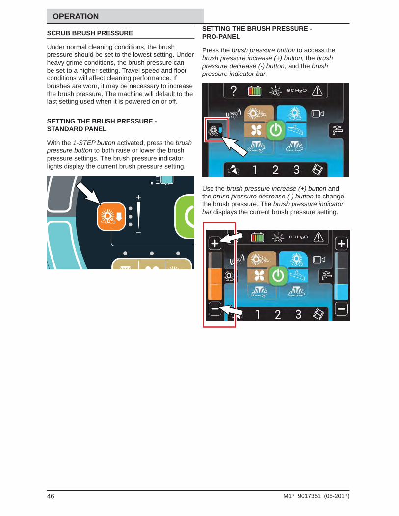
SCRUB BRUSH PRESSURE
Under normal cleaning conditions, the brush pressure should be set to the lowest setting. Under heavy grime conditions, the brush pressure can be set to a higher setting. Travel speed and fl oor conditions will affect cleaning performance. If brushes are worn, it may be necessary to increase the brush pressure. The machine will default to the last setting used when it is powered on or off.
SETTING THE BRUSH PRESSURE - STANDARD PANEL
With the 1-STEP button activated, press the brush pressure button to both raise or lower the brush pressure settings. The brush pressure indicator lights display the current brush pressure setting.
SETTING THE BRUSH PRESSURE - PRO-PANEL
Press the brush pressure button to access the brush pressure increase (+) button, the brush pressure decrease (-) button, and the brush pressure indicator bar.
Use the brush pressure increase (+) button and the brush pressure decrease (-) button to change the brush pressure. The brush pressure indicator bar displays the current brush pressure setting.
47M17 9017351 (05-2017)
OPERATION
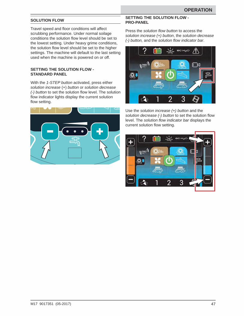
SOLUTION FLOW
Travel speed and fl oor conditions will affect scrubbing performance. Under normal soilage conditions the solution fl ow level should be set to the lowest setting. Under heavy grime conditions, the solution fl ow level should be set to the higher settings. The machine will default to the last setting used when the machine is powered on or off.
SETTING THE SOLUTION FLOW - STANDARD PANEL
With the 1-STEP button activated, press either solution increase (+) button or solution decrease (-) button to set the solution fl ow level. The solution fl ow indicator lights display the current solution fl ow setting.
SETTING THE SOLUTION FLOW - PRO-PANEL
Press the solution fl ow button to access the solution increase (+) button, the solution decrease (-) button, and the solution fl ow indicator bar.
Use the solution increase (+) button and the solution decrease (-) button to set the solution fl ow level. The solution fl ow indicator bar displays the current solution fl ow setting.
48 M17 9017351 (05-2017)
OPERATION
SCRUBBING / SWEEPING - STANDARD PANEL
FOR SAFETY: Do not operate machine, unless operator manual is read and understood.
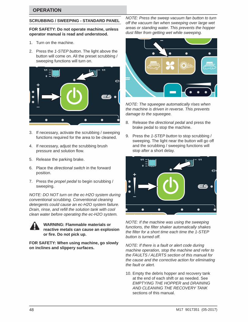
1. Turn on the machine.
2. Press the 1-STEP button. The light above the button will come on. All the preset scrubbing /sweeping functions will turn on.
3. If necessary, activate the scrubbing / sweeping functions required for the area to be cleaned.
4. If necessary, adjust the scrubbing brush pressure and solution fl ow.
5. Release the parking brake.
6. Place the directional switch in the forward position.
7. Press the propel pedal to begin scrubbing / sweeping.
NOTE: DO NOT turn on the ec-H2O system during conventional scrubbing. Conventional cleaning detergents could cause an ec-H2O system failure. Drain, rinse, and refi ll the solution tank with cool clean water before operating the ec-H2O system.
WARNING: Flammable materials or reactive metals can cause an explosion or fi re. Do not pick up.
FOR SAFETY: When using machine, go slowly on inclines and slippery surfaces.
NOTE: Press the sweep vacuum fan button to turn off the vacuum fan when sweeping over large wet areas or standing water. This prevents the hopper dust fi lter from getting wet while sweeping.
NOTE: The squeegee automatically rises when the machine is driven in reverse. This prevents damage to the squeegee.
8. Release the directional pedal and press the brake pedal to stop the machine.
9. Press the 1-STEP button to stop scrubbing / sweeping. The light near the button will go off and the scrubbing / sweeping functions will stop after a short delay.
NOTE: If the machine was using the sweeping functions, the fi lter shaker automatically shakes the fi lter for a short time each time the 1-STEP button is turned off.
NOTE: If there is a fault or alert code during machine operation, stop the machine and refer to the FAULTS / ALERTS section of this manual for the cause and the corrective action for eliminating the fault or alert.
10. Empty the debris hopper and recovery tank at the end of each shift or as needed. See EMPTYING THE HOPPER and DRAINING AND CLEANING THE RECOVERY TANK sections of this manual.
49M17 9017351 (05-2017)
OPERATION
SCRUBBING / SWEEPING - PRO-PANEL
FOR SAFETY: Do not operate machine, unless operator manual is read and understood.
1. Turn on the machine.
2. If applicable, log into the machine. See PRO-ID LOGIN SCREEN.
3. If applicable, complete the Pro-Check Pre-Operation Checklist. See COMPLETING THE PRO-CHECK PRE-OPERATION CHECKLIST.
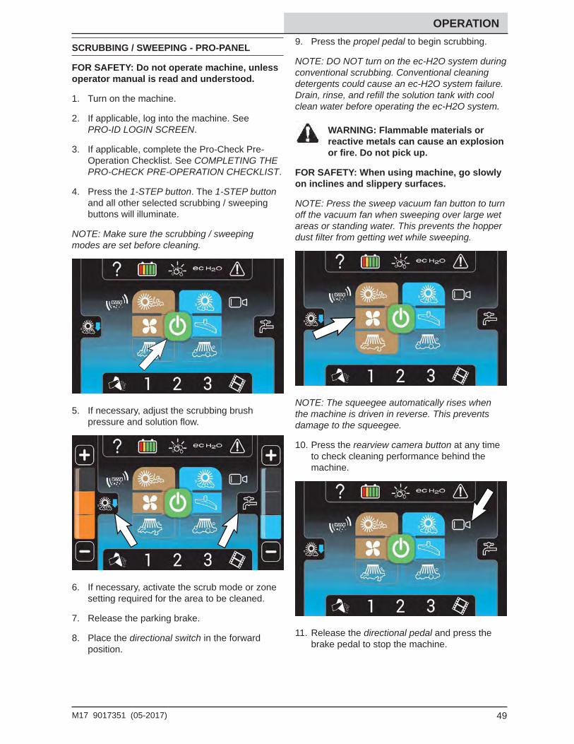
4. Press the 1-STEP button. The 1-STEP button and all other selected scrubbing / sweeping buttons will illuminate.
NOTE: Make sure the scrubbing / sweeping modes are set before cleaning.
5. If necessary, adjust the scrubbing brush pressure and solution fl ow.
6. If necessary, activate the scrub mode or zone setting required for the area to be cleaned.
7. Release the parking brake.
8. Place the directional switch in the forward position.
9. Press the propel pedal to begin scrubbing.
NOTE: DO NOT turn on the ec-H2O system during conventional scrubbing. Conventional cleaning detergents could cause an ec-H2O system failure. Drain, rinse, and refi ll the solution tank with cool clean water before operating the ec-H2O system.
WARNING: Flammable materials or reactive metals can cause an explosion or fi re. Do not pick up.
FOR SAFETY: When using machine, go slowly on inclines and slippery surfaces.
NOTE: Press the sweep vacuum fan button to turn off the vacuum fan when sweeping over large wet areas or standing water. This prevents the hopper dust fi lter from getting wet while sweeping.
NOTE: The squeegee automatically rises when the machine is driven in reverse. This prevents damage to the squeegee.
10. Press the rearview camera button at any time to check cleaning performance behind the machine.
11. Release the directional pedal and press the brake pedal to stop the machine.
50 M17 9017351 (05-2017)
OPERATION12. Press the 1-STEP button to stop scrubbing.
/ sweeping The button will no longer be illuminated and scrubbing / sweeping functions will stop after a short delay.
NOTE: If the machine was using the sweeping functions, the fi lter shaker automatically shakes the fi lter for a short time each time the 1-STEP button is turned off.
NOTE: If there is a fault or alert code during machine operation stop the machine and refer to the FAULTS / ALERTS section of this manual for the cause and the corrective action for eliminating the fault or alert.
13. Empty the debris hopper and recovery tank at the end of each shift or as needed. See EMPTYING THE HOPPER and DRAINING AND CLEANING THE RECOVERY TANK sections of this manual.
DOUBLE SCRUBBING
Double scrubbing is the process of making two or more passes over a heavily soiled area. The fi rst pass is made with the rear and side squeegees raised to allow the solution to soak into the fl oor. Use the double scrubbing method to clean heavily soiled areas.
Double scrubbing can be performed using the ec-H2O SCRUBBING SYSTEM (option), ES SCRUBBING SYSTEM (option), or CONVENTIONAL SCRUBBING methods.
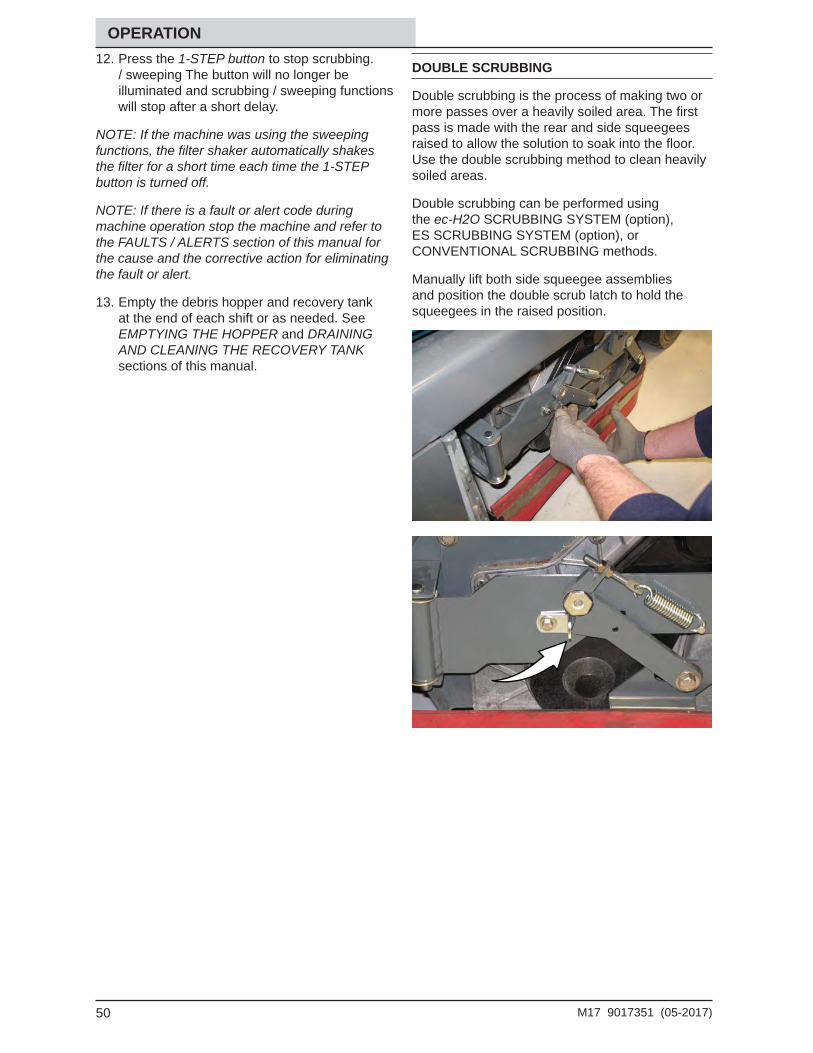
Manually lift both side squeegee assemblies and position the double scrub latch to hold the squeegees in the raised position.
51M17 9017351 (05-2017)
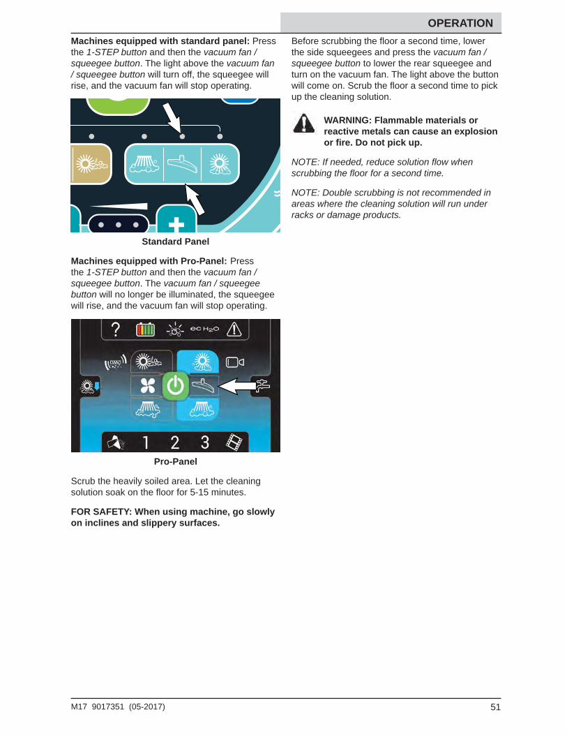
OPERATION Machines equipped with standard panel: Press the 1-STEP button and then the vacuum fan / squeegee button. The light above the vacuum fan / squeegee button will turn off, the squeegee will rise, and the vacuum fan will stop operating.
Standard Panel
Machines equipped with Pro-Panel: Press the 1-STEP button and then the vacuum fan / squeegee button. The vacuum fan / squeegee button will no longer be illuminated, the squeegee will rise, and the vacuum fan will stop operating.
Pro-Panel
Scrub the heavily soiled area. Let the cleaning solution soak on the fl oor for 5-15 minutes.
FOR SAFETY: When using machine, go slowly on inclines and slippery surfaces.
Before scrubbing the fl oor a second time, lower the side squeegees and press the vacuum fan /squeegee button to lower the rear squeegee and turn on the vacuum fan. The light above the button will come on. Scrub the fl oor a second time to pick up the cleaning solution.
WARNING: Flammable materials or reactive metals can cause an explosion or fi re. Do not pick up.
NOTE: If needed, reduce solution fl ow when scrubbing the fl oor for a second time.
NOTE: Double scrubbing is not recommended in areas where the cleaning solution will run under racks or damage products.
52 M17 9017351 (05-2017)
OPERATION
WATER PICKUP MODE (NO SCRUBBING)
The machine can be used to pick up water or non-fl ammable liquid spills without scrubbing.
WARNING: Flammable materials or reactive metals can cause an explosion or fi re. Do not pick up.
Before picking up water or non-fl ammable liquid spills, make sure the 1-STEP button is activated and all other cleaning functions are off.
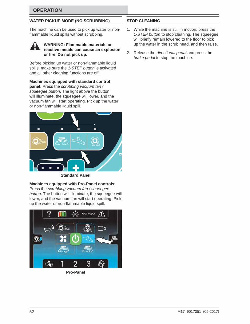
Machines equipped with standard control panel: Press the scrubbing vacuum fan / squeegee button. The light above the button will illuminate, the squeegee will lower, and the vacuum fan will start operating. Pick up the water or non-fl ammable liquid spill.
Standard Panel
Machines equipped with Pro-Panel controls: Press the scrubbing vacuum fan / squeegee button. The button will illuminate, the squeegee will lower, and the vacuum fan will start operating. Pick up the water or non-fl ammable liquid spill.
Pro-Panel
STOP CLEANING
1. While the machine is still in motion, press the 1-STEP button to stop cleaning. The squeegee will briefl y remain lowered to the fl oor to pick up the water in the scrub head, and then raise.
2. Release the directional pedal and press the brake pedal to stop the machine.
53M17 9017351 (05-2017)
OPERATION
EMPTYING THE HOPPER
EMPTYING THE HOPPER - STANDARD PANEL
1. Drive the machine to a debris site or container.
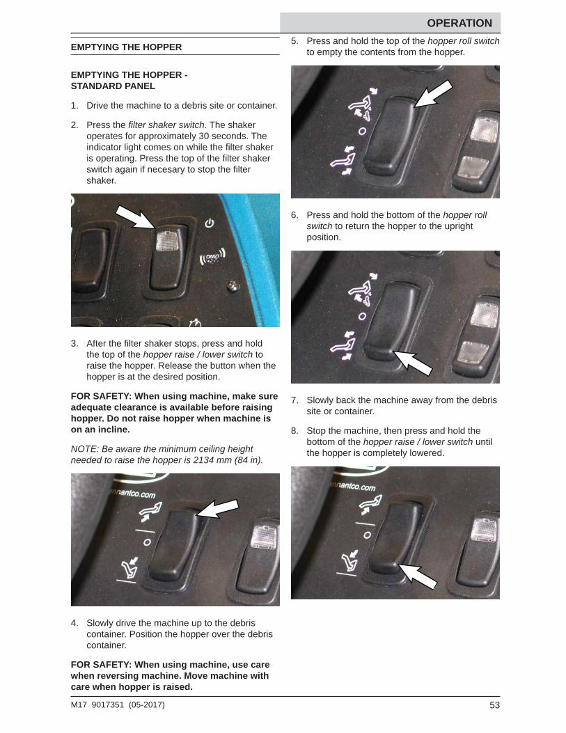
2. Press the fi lter shaker switch. The shaker operates for approximately 30 seconds. The indicator light comes on while the fi lter shaker is operating. Press the top of the fi lter shaker switch again if necesary to stop the fi lter shaker.
3. After the fi lter shaker stops, press and hold the top of the hopper raise / lower switch to raise the hopper. Release the button when the hopper is at the desired position.
FOR SAFETY: When using machine, make sure adequate clearance is available before raising hopper. Do not raise hopper when machine is on an incline.
NOTE: Be aware the minimum ceiling height needed to raise the hopper is 2134 mm (84 in).
4. Slowly drive the machine up to the debris container. Position the hopper over the debris container.
FOR SAFETY: When using machine, use care when reversing machine. Move machine with care when hopper is raised.
5. Press and hold the top of the hopper roll switch to empty the contents from the hopper.
6. Press and hold the bottom of the hopper roll switch to return the hopper to the upright position.
7. Slowly back the machine away from the debris site or container.
8. Stop the machine, then press and hold the bottom of the hopper raise / lower switch until the hopper is completely lowered.
54 M17 9017351 (05-2017)
OPERATION EMPTYING THE HOPPER - PRO-PANEL
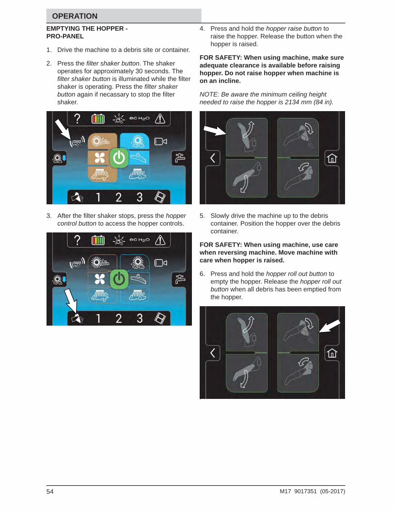
1. Drive the machine to a debris site or container.
2. Press the fi lter shaker button. The shaker operates for approximately 30 seconds. The fi lter shaker button is illuminated while the fi lter shaker is operating. Press the fi lter shaker button again if necassary to stop the fi lter shaker.
3. After the fi lter shaker stops, press the hopper control button to access the hopper controls.
4. Press and hold the hopper raise button to raise the hopper. Release the button when the hopper is raised.
FOR SAFETY: When using machine, make sure adequate clearance is available before raising hopper. Do not raise hopper when machine is on an incline.
NOTE: Be aware the minimum ceiling height needed to raise the hopper is 2134 mm (84 in).
5. Slowly drive the machine up to the debris container. Position the hopper over the debris container.
FOR SAFETY: When using machine, use care when reversing machine. Move machine with care when hopper is raised.
6. Press and hold the hopper roll out button to empty the hopper. Release the hopper roll out button when all debris has been emptied from the hopper.
.
55M17 9017351 (05-2017)
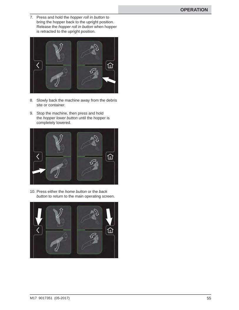
OPERATION 7. Press and hold the hopper roll in button to
bring the hopper back to the upright position. Release the hopper roll in button when hopper is retracted to the upright position.
8. Slowly back the machine away from the debris site or container.
9. Stop the machine, then press and hold the hopper lower button until the hopper is completely lowered.
10. Press either the home button or the back button to return to the main operating screen.
56 M17 9017351 (05-2017)
OPERATION
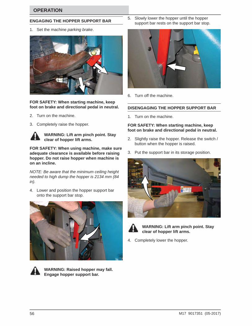
ENGAGING THE HOPPER SUPPORT BAR
1. Set the machine parking brake.
FOR SAFETY: When starting machine, keep foot on brake and directional pedal in neutral.
2. Turn on the machine.
3. Completely raise the hopper.
WARNING: Lift arm pinch point. Stay clear of hopper lift arms.
FOR SAFETY: When using machine, make sure adequate clearance is available before raising hopper. Do not raise hopper when machine is on an incline.
NOTE: Be aware that the minimum ceiling height needed to high dump the hopper is 2134 mm (84 in).
4. Lower and position the hopper support bar onto the support bar stop.
WARNING: Raised hopper may fall. Engage hopper support bar.
5. Slowly lower the hopper until the hopper support bar rests on the support bar stop.
6. Turn off the machine.
DISENGAGING THE HOPPER SUPPORT BAR
1. Turn on the machine.
FOR SAFETY: When starting machine, keep foot on brake and directional pedal in neutral.
2. Slightly raise the hopper. Release the switch / button when the hopper is raised.
3. Put the support bar in its storage position.
WARNING: Lift arm pinch point. Stay clear of hopper lift arms.
4. Completely lower the hopper.
57M17 9017351 (05-2017)
OPERATION
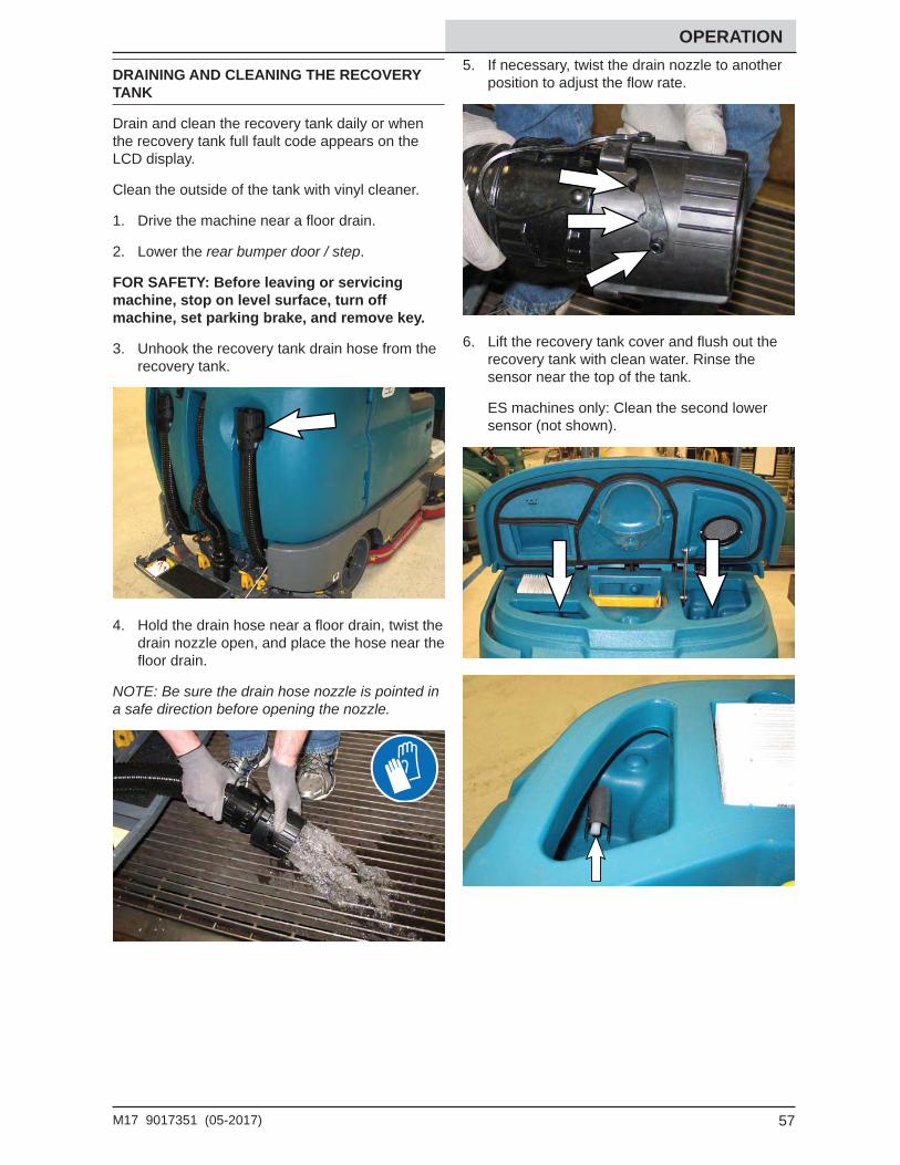
DRAINING AND CLEANING THE RECOVERY TANK
Drain and clean the recovery tank daily or when the recovery tank full fault code appears on the LCD display.
Clean the outside of the tank with vinyl cleaner.
1. Drive the machine near a fl oor drain.
2. Lower the rear bumper door / step.
FOR SAFETY: Before leaving or servicing machine, stop on level surface, turn off machine, set parking brake, and remove key.
3. Unhook the recovery tank drain hose from the recovery tank.
4. Hold the drain hose near a fl oor drain, twist the drain nozzle open, and place the hose near the fl oor drain.
NOTE: Be sure the drain hose nozzle is pointed in a safe direction before opening the nozzle.
5. If necessary, twist the drain nozzle to another position to adjust the fl ow rate.
6. Lift the recovery tank cover and fl ush out the recovery tank with clean water. Rinse the sensor near the top of the tank.
ES machines only: Clean the second lower sensor (not shown).
58 M17 9017351 (05-2017)
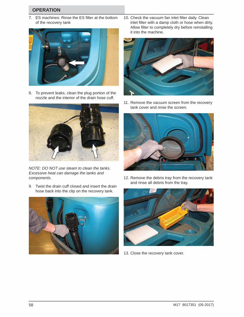
OPERATION7. ES machines: Rinse the ES fi lter at the bottom
of the recovery tank
8. To prevent leaks, clean the plug portion of the nozzle and the interior of the drain hose cuff.
NOTE: DO NOT use steam to clean the tanks. Excessive heat can damage the tanks and components.
9. Twist the drain cuff closed and insert the drain hose back into the clip on the recovery tank.
10. Check the vacuum fan inlet fi lter daily. Clean inlet fi lter with a damp cloth or hose when dirty. Allow fi lter to completely dry before reinstalling it into the machine.
11. Remove the vacuum screen from the recovery tank cover and rinse the screen.
12. Remove the debris tray from the recovery tank and rinse all debris from the tray.
13. Close the recovery tank cover.
59M17 9017351 (05-2017)
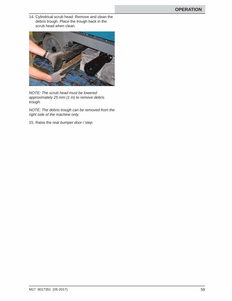
OPERATION 14. Cylindrical scrub head: Remove and clean the
debris trough. Place the trough back in the scrub head when clean.
NOTE: The scrub head must be lowered approximately 25 mm (1 in) to remove debris trough.
NOTE: The debris trough can be removed from the right side of the machine only.
15. Raise the rear bumper door / step.
60 M17 9017351 (05-2017)
OPERATION
DRAINING AND CLEANING THE SOLUTION TANK
Machines equipped with ES (Extended Scrub) only: Drain and clean the solution tank daily.
Clean the outside of the tank with vinyl cleaner.
1. Drive the machine near a fl oor drain.
FOR SAFETY: Before leaving or servicing machine, stop on level surface, turn off machine, set parking brake, and remove key.
2. Lower the rear bumper door / step.
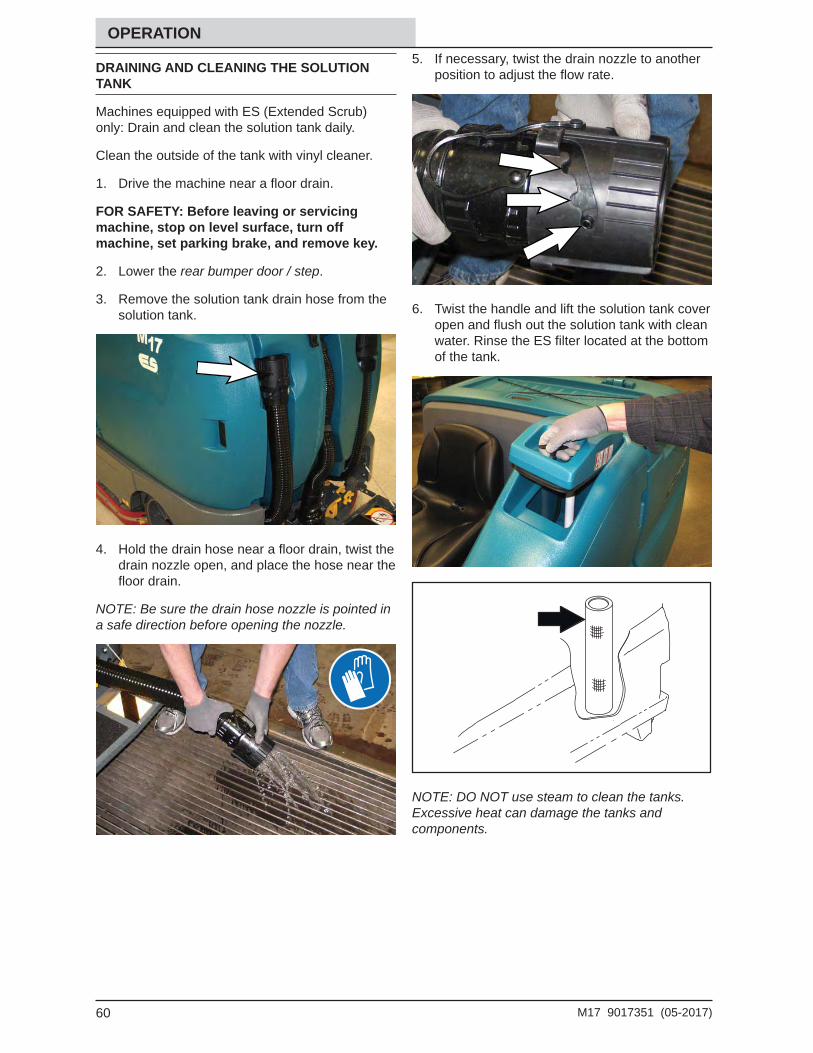
3. Remove the solution tank drain hose from the solution tank.
4. Hold the drain hose near a fl oor drain, twist the drain nozzle open, and place the hose near the fl oor drain.
NOTE: Be sure the drain hose nozzle is pointed in a safe direction before opening the nozzle.
5. If necessary, twist the drain nozzle to another position to adjust the fl ow rate.
6. Twist the handle and lift the solution tank cover open and fl ush out the solution tank with clean water. Rinse the ES fi lter located at the bottom of the tank.
NOTE: DO NOT use steam to clean the tanks. Excessive heat can damage the tanks and components.
61M17 9017351 (05-2017)
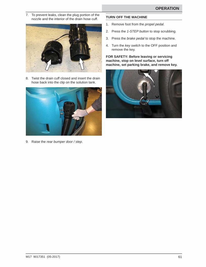
OPERATION 7. To prevent leaks, clean the plug portion of the
nozzle and the interior of the drain hose cuff.
8. Twist the drain cuff closed and insert the drain hose back into the clip on the solution tank.
9. Raise the rear bumper door / step.
TURN OFF THE MACHINE
1. Remove foot from the propel pedal.
2. Press the 1-STEP button to stop scrubbing.
3. Press the brake pedal to stop the machine.
4. Turn the key switch to the OFF position and remove the key.
FOR SAFETY: Before leaving or servicing machine, stop on level surface, turn off machine, set parking brake, and remove key.
62 M17 9017351 (05-2017)
OPERATION
FAULTS / ALERTS
The operator will receive a fault / alert warning when there is a mechanical / electronic issue with the machine.
To reset the fault / alert indicators, turn off the machine and then eliminate the cause of the fault / alert. The fault / alert indicator will reset when the machine is restarted.
Refer to the fault / alert indicators table to determine the cause and remedy for the fault / alert.
FAULT / ALERT INDICATORS - STANDARD PANEL
This machine is equipped with two visual indicators, a red indicator light and an LCD (liquid crystal display).
The red indicator light will blink continuously indicating that a fault / alert has occurred.
The LCD will display a fault / alert code. If there is more than one fault, each fault code will alternately display.
FAULT / ALERT INDICATORS - PRO-PANEL
The fault / alert indicator button will fl ash continuously indicating a fault / alert has occurred. The multicolored background will change to a black background
Press the fl ashing red fault indicator button to view the faults. A fault / alert screen will appear in the display.
Press the fl ashing yellow alert indicator button to view the alerts. A fault / alert screen will appear in the display.
Fault / alert text will appear under the icon in the center of the screen.
Press right arrow button to scroll forward through the faults / alerts.
Press left arrow button to scroll back through the faults / alerts.
Press the home button to return to the main operating screen.
Press the back arrow button to return to the previous screen.
0101 L Scrub Opn Left Scrub Motor Electrical Open Alert
Electrical fault Contact qualifi ed Tennant service representative.
NOTE: Contact a Tennant Service representative for all other fault codes.
64 M17 9017351 (05-2017)
OPERATION
OPTIONS
SPRAY NOZZLE (OPTION)
The spray nozzle is used to clean the machine and surrounding areas. The solution tank provides a water/solution supply for the spray nozzle.
FOR SAFETY: When servicing machine, do not power spray or hose off machine near electrical components.
FOR SAFETY: Before leaving or servicing machine and stop on level surface and set parking brake.
1. Turn on the machine.
2. Press the top of the spray nozzle switch to turn on the spray nozzle. The light on the switch will come on when the spray nozzle is turned on.
3. Open the left shroud to access the spray nozzle.
4. Pull the spray nozzle out from the back of the machine and clean as needed.
5. When fi nished cleaning, gently pull the hose and allow the spray nozzle hose to retract back into the machine.
NOTE: Continue holding onto the spray nozzle and control the hose while it is retracting back into the machine. The machine and / or the spray nozzle assembly could be damaged if the spray nozzle hose is released and allowed to rapidly retract into the machine.
6. Press the bottom of the spray nozzle switch to turn off the water supply. The light on the switch will turn off when the spray nozzle is turned off.
NOTE: Be sure the spray nozzle switch is turned off before continuing scrubbing. The spray nozzle pump could be damaged if the switch is left on while scrubbing.
65M17 9017351 (05-2017)
OPERATION VACUUM WAND (OPTION)
Use the vacuum wand to clean areas that are out of reach of the machine.
WARNING: Flammable materials or reactive metals can cause an explosion or fi re. Do not pick up.
FOR SAFETY: Before leaving or servicing machine and stop on level surface and set parking brake.
1. Lower the rear bumper door / step.
2. Remove the vacuum wand components from the storage tray located on top the battery compartment cover.
3. Disconnect the vacuum hose from the rear squeegee.
4. Connect the vacuum wand hose to the rear squeegee vacuum hose.
5. Connect the vacuum wand nozzle to the vacuum wand nozzle hose.
6. Insert and tighten the vacuum wand handle into the vacuum wand nozzle.
66 M17 9017351 (05-2017)
OPERATION7. Secure the vacuum wand hose collar to the
vacuum hose handle.
8. Extend the vacuum wand handle to the desired length and twist the vacuum wand handle to tighten.
9. Turn on the machine.
10. Press the vacuum fan / squeegee button to turn on the vacuum fan. The squeegee will completely lower.
Standard Panel Pro-Panel
11. Vacuum the fl oor.
12. When fi nished vacuuming, press the vacuum fan / squeegee button to turn off the vacuum fan. The squeegee will raise.
13. Turn off the machine.
14. Disconnect the vacuum wand hose from the rear squeegee vacuum hose and disassemble the vacuum wand.
15. Return the vacuum wand components to the storage tray located on top the battery compartment cover.
16. Reconnect the vacuum hose to the rear squeegee.
17. Lift the rear bumper door / step to the raised position and secure to the rear bumper.
67M17 9017351 (05-2017)
OPERATION SLIDE OUT BATTERY (OPTION)
The slide out battery allows the operator a quick and easy way to remove and replace the batteries. Use proper battery pulling and lifting equipment and procedures based on the battery size and weight. See SPECIFICATIONS section. The battery slide out height is 508 mm (20 in.).
FOR SAFETY: Before leaving or servicing machine, stop on level surface, turn off machine, set parking brake, and remove key.
1. Lift the battery compartment cover open and engage the support.
2. Open the right shroud.
3. Disconnect the battery cable from the machine connector.
4. Remove the battery retainer plate from the machine.
5. Position the battery cart near the battery compartment.
FOR SAFETY: When servicing machine: Keep all metal objects off batteries. Use a non-conductive battery removal device. Use a hoist and adequate assistance when lifting batteries. Battery installation must be done by trained personnel. Follow site safety guidelines concerning battery removal.
6. Slide the battery from the machine and onto the battery cart.
7. Install the new battery into the battery compartment.
8. Reinstall the battery retainer plate onto the machine. The retainer plate must press the switch completely down into the engaged position. The machine will not function if the switch is not engaged.
9. Close the battery compartment side cover and top cover.
68 M17 9017351 (05-2017)
OPERATION REAR SQUEEGEE GUARD (OPTION)
The rear squeegee protector helps protect the rear squeegee from being damaged.
To engage the rear squeegee protector, pull the pin, lower the protector bar, and reinsert the pin.
ADJUSTING BACKUP ALARM VOLUME (OPTION)
FOR SAFETY: When using machine, follow site safety guidlines concerning backup alarms.
The backup alarm volume can be adjusted from 85−102 dB(A). To adjust the volume, remove the backup alarm cover and turn the volume knob.
Increase volume: Turn the knob clockwise.
Decrease volume: Turn the knob counter−clockwise.
69M17 9017351 (05-2017)
OPERATION MACHINE TROUBLESHOOTING
Problem Cause RemedyMachine will not operate
Emergency stop button activated Reset emergency stop buttonMachine fault detected See FAULT INDICATORS or
representativeFaulty control board Contact Tennant service
representativeTrailing water - poor or no water pickup
Squeegee blades worn Rotate or replace squeegee bladesSqueegee out of adjustment Adjust squeegeeClogged squeegee assembly Clean squeegee assemblyVacuum hose loose Secure vacuum hose connectionsVacuum hose damaged Replace vacuum hoseVacuum fan inlet fi lter dirty Clean inlet fi lterDebris caught on squeegee Remove debris from squeegeeVacuum hose to squeegee or recovery tank disconnected or damaged
Reconnect or replace vacuum hose
Tank cover not completely closed Check for obstructionsTorn seals on recovery tank Replace seals
Scrubbing vacuum fan will not turn on
Recovery tank full Drain recovery tankFoam fi lling recovery tank Empty recovery tank
Use less or change detergentUse a defoamer
Little or no solution fl ow to the fl oor
Solution tank empty Fill solution tankSolution fl ow turned off Turn solution fl ow onSolution supply lines plugged Flush solution supply linesSolution solenoid clogged or stuck Clean or replace
Poor scrubbing performance
Debris caught on scrub brushes Remove debris from brushesImproper detergent / brushes pads used
Contact Tennant representative for recommendations
Scrub brushes pads worn Replace scrub brushes / padsExcessive brush pressure Reduce scrub brush down pressureUneven brush pressure Level scrub headDebris trough full Empty debris troughBroken brush drive belts on cylindrical scrub head
Replace belts
Low battery charge Charge battery until the charger automatically turns off
70 M17 9017351 (05-2017)
OPERATION
Problem Cause RemedyExcessive dusting Brush skirts and dust seals worn,
damaged, or out of adjustmentReplace or adjust brush skirts and/or brush seals
Hopper dust fi lter clogged Shake and / or replace dust fi lterSweep vacuum fan seal damaged Replace vacuum fan sealSweep vacuum fan failure Contact Tennant service
representativeThermo-Sentry tripped Allow Thermo-Sentry to coolSweeping vacuum fan off Turn on vacuum fanPerma-Filter clogged Clean Perma-Filter
Poor sweeping performance
Worn brush bristles Replace brushesDebris caught in main brush drive mechanism
Remove debris from main brush drive mechanism
Main and/or side brush drive failure Contact Tennant service representative
Hopper full Empty hopperHopper lip skirts worn or damaged Replace lip skirtsWrong sweeping brush Contact Tennant service
representativeReduced run time Battery not fully charged Charge battery until the charger
automatically turns offDefective battery Replace batteryBatteries need maintenance See BATTERIES in MAINTENANCEFaulty battery charger Replace battery charger
ES System does not function
ES button is turned off Turn on ES buttonES sensor in tank dirty or not in correct position
Clean / reposition sensor
Clogged ES pump fi lter Clogged ES pump fi lterWater level in recovery tank too low Fill recovery tank approximately half
fullWater level in solution tank too low Fill solution tank
Sweeping or Scrubbing functions do not turn on
Hopper is up Completely lower hopperFire in the hopper Turn off machine. Extinguish fi re.
If necessary, call emergency personnel.
Recovery tank full Press the Scrub vacuum fan/squeegee button for one minute of extended water pickup. Empty recovery tank.
ES models: Activate the ES system to prevent this.
71M17 9017351 (05-2017)
OPERATION
Problem Cause Remedyec-H2O Model:
Warning and fault indicator light blinking red
Mineral deposit build-up in module Flush module (See ec-H2O MODULE FLUSH PROCEDURE)
ec-H2O Model:
Warning and fault indicator light solid red
Clogged module Contact Tennant service representative
Defective solution pump Replace solution pump
72 M17 9017351 (05-2017)
MAINTENANCE
MAINTENANCE
23 1121221187
174 5
3
20
22
11
17
10
17
21 6 14 9 8
13
16
21
19
2
15 7
24
25
73M17 9017351 (05-2017)
MAINTENANCE
MAINTENANCE CHART
The table below indicates the Person Responsible for each procedure.
O = Operator.T = Trained Personnel.
NOTE:Check procedures indicated (■) after the fi rst 50 hours of operation.
Interval Person Resp.
Key Description Procedure Lubricant/Fluid
No. of Service Points
Daily O 22 Hydraulic reservoir Check hydraulic fl uid level HYDO 1O 1 Side and rear squeegees Check for damage and wear.
Check defl ection.- 4
O 2 Main brushes and pads Check for damage, wear, and debris
- 2
O 3 Recovery tank Clean tank, top sensor, and check cover seal
- 1
O 4 Solution tank Check cover seal - 1O 3 ES machines only:
Recovery tankClean tank and level sensor - 2
O 4 ES machines only: Solution tank
Clean tank and level sensor - 1
O 5 Vacuum fan inlet fi lter, screen, and debris tray
Clean - 1
O 6 Cylindrical brushes only: Debris trough
Clean - 1
O 7 Sweeping side brush(es) Check for damage, wear, debris
- 1 (2)
O 8 Scrubbing side brush Check for damage, wear, debris
- 1
O 9 Scrubbing side brush squeegee
Check for damage and wear - 1
O 10 Hopper dust fi lter Shake to clean - 1Weekly T 11 Battery cells Check electrolyte level DW Multiple50 Hours T 1 Side and rear squeegees Check leveling - 4
O 1 Main brushes (cylindrical) Rotate brushes from front to rear
- 2
O 12 Scrub head skirts (disk) Check for damage and wear - 2O 23 Sweeping skirts Check for damage and wear - 4O 7 Sweeping side brush(es) Check brush pattern - 2O 25 Solution supply fi lter Check screen and clean - 1
LUBRICANT/FLUID
DW Distilled water.SPL Special lubricant, Lubriplate EMB grease (Tennant part number 01433-1)GL SAE 90 weight gear lubricantHYDO Tennant True premium hydraulic fl uid or equivalent
NOTE: More frequent maintenance intervals may be required in extremely dusty conditions.
74 M17 9017351 (05-2017)
MAINTENANCE
The table below indicates the Person Responsible for each procedure.
O = Operator.T = Trained Personnel.
NOTE:Check procedures indicated (■) after the fi rst 50 hours of operation.
Interval Person Resp
Key Description Procedure Lubricant/Fluid
No. of Service Points
100 Hours
T 11 Battery watering system (option)
Check hoses and connections for damage and wear
- Multiple
T 10 Hopper seals Check for damage and wear - 2T 10 Hopper Clean hopper, dust fi lter and
Perma-Filter1
200 Hours
T 13 Brakes Check adjustments - 1T 11 Battery terminals and
cablesCheck and clean - Multiple
T 14 Cylindrical brush drive belts
Check for damage and wear - 2
T 18 Sweeping brush drive belts
Check for damage and wear - 2
T 15 Drive wheel pivot Lubricate SPL 1T 15 Steering chain Lubricate and check for dam-
age and wear.GL 1
16 Steering gear chain Lubricate and check for dam-age and wear
GL 1
T 24 Hopper chains Lubricate and check for dam-age and wear.
GL 2
T 17 Hopper lift arm pivots Lubricate SPL 3500 Hours
T 19 Scrub vacuum fan motor(s)
Check motor brushes - 1 (2)
O 21 Tires Check for damage and wear - 3T 24 Hopper chains ■ Check tension. - 2
800 Hours
T 22 Hydraulic hoses Check for wear and damage - Multiple
1000 Hours
T 7 Sweeping side brush motors
Check motor brushes (Check every 100 hours after initial 1000 hour check)
- 2
2400 Hours
T 22 Hydraulic reservoir Change hydraulic fl uid HYDO 1
LUBRICANT/FLUID
DW Distilled water.SPL Special lubricant, Lubriplate EMB grease (Tennant part number 01433-1)GL SAE 90 weight gear lubricantHYDO Tennant True premium hydraulic fl uid or equivalent
NOTE: More frequent maintenance intervals may be required in extremely dusty conditions.
75M17 9017351 (05-2017)
MAINTENANCE
YELLOW TOUCH POINTS
This machine features easy to fi nd yellow touch points for simple service items. No tools are required to perform these maintenance operations.
LUBRICATION
FOR SAFETY: Before leaving or servicing machine, stop on level surface, turn off machine, set parking brake, and remove key.
STEERING CHAIN
The steering chain is located on the steering column directly under the control panel. Check for damage or wear and lubricate the steering chain after every 200 hours.
STEERING GEAR CHAIN
The steering gear chain is located directly above the front tire. Check for damage or wear and lubricate the steering gear chain after every 200 hours.
DRIVE WHEEL PIVOT
The drive wheel pivot is located directly above the drive wheel. Lubricate the drive wheel pivot after every 200 hours.
HOPPER CHAINS
The hopper chains are located on the left hand side of the machine. Check for damage or wear and lubricate the hopper chains after every 200 hours..
76 M17 9017351 (05-2017)
MAINTENANCE HOPPER LIFT ARM PIVOTS
Lubricate the hopper lift arm pivots after every 200 hours of operation.
HOPPER CHAINS
The hopper chains are located on the left hand side of the machine. Check the tension of the hopper chains after the fi rst 50 hours of operation then every 500 hours after that.
With the hopper in the lowered position; the longer arm chain (A) should not move more than 25 mm (1 in) and the shorter lintel chain (B) should not move more than 12 mm (0.5 in).
B
A
77M17 9017351 (05-2017)
MAINTENANCE
HYDRAULICS
Check the hydraulic fl uid level at operating temperature daily. The hydraulic fl uid level should be between the MIN and MAX markings on the hydraulic reservoir. The hopper must be down when checking hydraulic fl uid level.
ATTENTION! Do not overfi ll the hydraulic fl uid reservoir or operate the machine with a low level of hydraulic fl uid in the reservoir. Damage to the machine hydraulic system may result.
Drain and refi ll the hydraulic fl uid reservoir with new TennantTrue premium hydraulic fl uid after every 2400 hours of operation.
1057707 3.8 L (1 gal) ISO 32 VI 163 or higher1057708 19 L (5 gal)
If using a locally-available hydraulic fl uid, be sure the specifi cations match Tennant hydraulic fl uid specifi cations. Substitute fl uids can cause premature failure of hydraulic components.
ATTENTION! Hydraulic components depend on system hydraulic fl uid for internal lubrication. Malfunctions, accelerated wear, and damage will result if dirt or other contaminants enter the hydraulic system.
HYDRAULIC HOSES
Check the hydraulic hoses after every 800 hours of operation for wear or damage.
FOR SAFETY: When servicing machine, use cardboard to locate leaking hydraulic fl uid under pressure.
High pressure fl uid escaping from a very small hole can almost be invisible, and can cause serious injuries.
00002
Consult a physician immediately if injury results from escaping hydraulic fl uid. Serious infection or reaction can occur if proper medical treatment is not given immediately.
Contact a mechanic or supervisor if a leak is discovered.
79M17 9017351 (05-2017)
MAINTENANCE
BATTERY
FOR SAFETY: Before leaving or servicing machine, stop on level surface, turn off machine, set parking brake (if equipped), and remove key.
The lifetime of the battery depends on proper maintenance. To get the most life from the battery:
– Do not leave the battery partially discharged for long period of time.
– Only charge the battery in a well ventilated area to prevent gas build up. Charge batteries in areas with ambient temperatures 27°C (80°F) or less.
– Maintain the proper electrolyte levels of the fl ooded (wet) battery by checking levels weekly.
The following steps do not apply if Opportunity charging (See OPPORTUNITY CHARGING section.
– Do not charge the battery more than once a day and only after running the machine for a minimum of 15 minutes.
– Allow the charger to completely charge the battery before re using the machine.
CHECKING THE ELECTROLYTE LEVEL
The fl ooded (wet) lead-acid battery requires routine maintenance as described below. Check the battery electrolyte level weekly.
NOTE: Do Not check the electrolyte level if the machine is equipped with the battery watering system. Proceed to the BATTERY WATERING SYSTEM (OPTION).
08247
FOR SAFETY: When servicing machine, keep all metal objects off batteries. Avoid contact with battery acid.
The level should be slightly above the battery plates as shown before charging. Add distilled water if low. DO NOT OVERFILL. The electrolyte will expand and may overfl ow when charging. After charging, distilled water can be added up to about 3 mm (0.12 in) below the sight tubes.
Before Charging After Charging
NOTE: Make sure the battery caps are in place while charging. There may be a sulfur smell after charging batteries. This is normal.
80 M17 9017351 (05-2017)
MAINTENANCEMAINTENANCE-FREE BATTERIES
Maintenance-free batteries do not require watering. Cleaning and other routine maintenance is still required.
CHECKING CONNECTIONS / CLEANING
After every 200 hours of use check for loose battery connections and clean the surface of the batteries, including terminals and cable clamps, with a strong solution of baking soda and water. Replace any worn or damaged wires. Do not remove battery caps when cleaning batteries.
81M17 9017351 (05-2017)
MAINTENANCE CHARGING THE BATTERY
IMPORTANT: Before charging, make sure that the machine and charger settings are properly set for the battery type.
NOTE: Use a charger with the proper rating for the batteries to prevent damage to the batteries or reduce the battery life.
NOTE: Do not opportunity charge standard batteries since doing so can shorten battery life.
1. Drive the machine to a fl at, dry surface in a well-ventilated area.
2. Stop the machine and turn off the machine power.
FOR SAFETY: Before leaving or servicing machine, stop on level surface, turn off machine, set parking brake, and remove key.
3. Lift the battery compartment top cover open and engage the support.
NOTE: Make sure the batteries have the proper electrolyte level before charging. See CHECKING THE ELECTROLYTE LEVEL.
4. Plug the charger AC power supply cord into a properly grounded outlet.
5. Disconnect the battery cable from the machine connector.
6. Connect the charger connector to the battery cable.
TO CHARGE WITH TENNANT BRANDED CHARGER
1. Turn on the battery charger if required.
WARNING: Batteries emit hydrogen gas. Explosion or fi re can result. Keep sparks and open fl ame away. Keep covers open when charging.
NOTE: If there are charger fault codes when the battery is plugged into the battery charger, the fault codes will appear at the bottom of the charger display. Refer to the battery charger manual for fault code defi nitions
82 M17 9017351 (05-2017)
MAINTENANCE2. Observe the charger display. CHARGE
appears on the display when the battery is charging. This is the charger default screen.
10. If necessary, press the navigation buttons to access additional screens. Press the charger stop / start / enter button to enter selection. The charger will return to the default screen. Refer to manufacturers operator manual for additional information.
NOTE: If the charger cable must be disconnected from the battery before they are fully charged, press the charger stop / start / enter button to stop charging. Be sure STOP appears on the display and the red stop charge light is illuminated before disconnecting the battery charger cable.
11. The charger status indicators will illuminate from left to the right as the battery is charging. COMPLETE will appear in the display, all the charger status indicators will be illuminated, and the Tennant charger will stop charging when the battery is completely charged.
83M17 9017351 (05-2017)
MAINTENANCE 12. After the batteries have completely charged,
disconnect the charger connector from the battery cable connector.
13. Reconnect the battery connector to the machine connector.
FOR SAFETY: When servicing machine do not disconnect the off-board charger’s DC cord from the machine receptacle when the charger is operating. Arcing may result. If the charger must be interrupted during charging, disconnect the AC power supply cord fi rst.
14. Close the battery compartment top cover.
TO CHARGE WITH ENERSYS BATTERY CHARGER
1. Turn on battery charger if required.
WARNING: Batteries emit hydrogen gas. Explosion or fi re can result. Keep sparks and open fl ame away. Keep covers open when charging.
NOTE: If there are charger fault codes when the battery is plugged into the battery charger, the fault codes will appear on the charger display. Refer to the battery charger manual for fault code defi nitions.
2. Observer the charger display. The charging indicator will illuminate on the display when the battery is charging. This is the charger default screen.
84 M17 9017351 (05-2017)
MAINTENANCECharger Display:
ABC
D
FG
E
A. Charge profi le number
C. Charger rating (Volts and current)
D. Battery voltage (Volts)
E. Charger current (Ampres)
F. Ampere hours charged
G. Time charged
H. Percent of charge
9. If necessary, press the navigation buttons to access additional screens. Press the charger stop/start/enter button to enter the selection. The charger will return to the default screen. Refer to manufacture’s operator manual for additional information.
NOTE: If the charger cable must be disconnected from the battery before they are fully charged, press the charger stop / start / enter button to stop charging. Be sure the charging indicator is no longer illuminated before disconnecting the battery charger cable.
10. The yellow charging indicator will illuminate while the battery is charging. Once the charging is complete the yellow charging indicator light will go out and the green charge complete indicator will be illuminated. The charger will stop charging when the battery is completely charged.
11. After the batteries have completely charged, disconnect the charger connector from the battery cable connector.
85M17 9017351 (05-2017)
MAINTENANCE 12. Reconnect the battery connector to the
machine connector.
FOR SAFETY: When servicing machine do not disconnect the off−board charger’s DC cord from the machine receptacle when the charger is operating. Arcing may result. If the charger must be interrupted during charging, disconnect the AC power supply cord fi rst.
13. Close the battery compartment top cover.
FOR SAFETY: Before leaving or servicing machine, stop on level surface, turn off machine, set parking brake, and remove key.
BATTERY CHARGER USB PORT
The battery charger USB port is for maintenance computer access to the charger by authorized service personnel only. Do Not plug cell phones or other unauthorized electronic devices into the battery charger USB port. Do Not plug anything into the USB port while the battery is charging.
OPPORTUNITY CHARGING (OPTION)
Opportunity charging is used to extend machine run time and productivity by allowing batteries to be charged during breaks, lunch, between shifts, or whenever there is an “opportunity” to charge.
IMPORTANT: Before charging, make sure that the machine and charger settings are properly set for the battery type.
NOTE: The machine must be equipped with a battery capable of being opportunity charged. Do not opportunity charge standard batteries since doing so can shorten battery life.
1. Drive the machine to a fl at, dry surface in a well-ventilated area.
2. Stop the machine and turn off the machine power.
FOR SAFETY: Before leaving or servicing machine, stop on level surface, turn off machine, set parking brake, and remove key.
3. Lift the battery compartment top cover open and engage the support.
NOTE: Make sure the batteries have the proper electrolyte level before charging. See CHECKING THE ELECTROLYTE LEVEL.
4. Disconnect the battery cable from the machine connector.
86 M17 9017351 (05-2017)
MAINTENANCE5. Connect the charger connector to the battery
cable.
6. The battery will be opportunity charged during the break.
7. When ready to start using the machine again press the charger stop / start button to stop the charger.
FOR SAFETY: When servicing machine do not disconnect the off-board charger’s DC cord from the machine receptacle when the charger is operating. Arcing may result. If the charger must be interrupted during charging, press charger stop / start button to stop charger.
8. Disconnect the charger connector from the battery cable connector.
9. Reconnect the battery connector to the machine connector.
10. Close the battery compartment top cover.
WEEKLY EQUALIZATION CHARGE
The opportunity charger is programmed to automatically provide a full equalization charge at a designated weekly interval.
IMPORTANT: The weekly equalization charge must be completed in its entirety. If it is interrupted during charging, it must be allowed to complete the equalization charge the next time it is started or it could damage the battery or severely shorten the battery life.
NOTE: Sunday is the default day for the charger to conduct a full equalization charge to the battery. The default day can be changed to another day if necessary. Consult a Tennant service representative about changing the default day.
Allow the charger to fully complete the equalization charge. The yellow charging indicator will be illuminated and the charging status will be displayed in the graphic display.
87M17 9017351 (05-2017)
MAINTENANCE The yellow charging indicator will go out and the green charge complete indicator will be illuminated when the battery equalization charge is complete.
88 M17 9017351 (05-2017)
MAINTENANCEBATTERY WATERING SYSTEM (OPTION)
The optional battery watering system provides a safe and easy way to maintain the proper electrolyte levels in the batteries.
Check the battery watering system hoses and connections for damage or wear after every 100 hours.
FOR SAFETY: Before leaving or servicing machine, stop on level surface, turn off machine, set parking brake, and remove key.
1. Lift the battery compartment cover open and engage the support.
2. Fully charge batteries prior to using the battery watering system. Do not add water to batteries before charging, the electrolyte level will expand and may overfl ow when charging. See CHARGING THE BATTERIES.
3. Connect the battery watering system hose to the water supply source.
NOTE: Water quality is important to maintain the life of the battery. Always use water that meets battery manufacturer requirements.
NOTE: The water supply to the battery water system must always be 7.57 LPM (2 GPM) or more. Use the purger to confi rm the water supply pressure. Refer to manufacturer Operator Manual for additional information.
4. Connect the battery watering system hose to the battery fi ll hose.
5. Turn on the water supply. The indicator inside the fl ow indicator will spin. The indicator stops spinning when the batteries are full.
6. Disconnect the battery watering system hose from the water supply hose.
7. Turn off the water supply.
8. After adding water, return the battery watering system hose to the storage location for future use.
89M17 9017351 (05-2017)
MAINTENANCE
CIRCUIT BREAKERS, FUSES, AND RELAYS
CIRCUIT BREAKERS
Circuit breakers are resettable electrical circuit protection devices designed to stop the fl ow of current in the event of a circuit overload. Once a circuit breaker is tripped, reset it manually by pressing the reset button after the breaker has cooled down.
Circuit breakers 1 through 9 are located under the operator seat behind the battery compartment side cover.
Circuit breakers 10 through 15 are located behind the steering shroud access panel.
Circuit breakers 16 through 20 are located in the hopper compartment.
Circuit breaker 21 is located inside the optional light assembly mounted on top of the recovery tank.
If the overload that caused the circuit breaker to trip is still present, the circuit breaker will continue to stop current fl ow until the problem is corrected.
The chart below shows the circuit breakers and the electrical components they protect.
Circuit Breaker
Rating Circuit Protected
CB1 60A Water pickup moduleCB2 - Not usedCB3 35A Side brush scrub module
(Option)CB4 2.5A Key switchCB5 2.5A Water pick up moduleCB6 2.5A Scrub moduleCB7 2.5A Side brush scrub module
Fuses are one-time protection devices designed to stop the fl ow of current in the event of a circuit overload. Never substitute higher value fuses than specifi ed.
The fuses are located in the control box behind the circuit breaker panel or inline on harnesses and cables.
Relays are electrical switches that open and close under the control of another electrical circuit. Relays are able to control an output circuit of higher power than the input circuit. The relays are located in the control box behind the circuit breaker panel.
Refer to the table below for the relays and circuits controlled.
Relay Rating Circuit ControlledM1 36 VDC, 200 A Main contactorM2 36 VDC, 5 A Backup alarm / light
(Option)M3 36 VDC, 100 A Auxiliary line contactorM4 36 VDC, 200A Sweep contactor
ELECTRIC MOTORS
Inspect the carbon brushes on the scrubbing vacuum fan motors after every 500 hours of operation. Inspect the carbon brushes on the scrubbing side brush motors after the fi rst 1000 hours of operation and every 100 hours after the initial check. Refer to the table below for carbon brush inspection intervals.
Carbon Brush Inspection HoursSide brush motors - Sweeping (Option) 1000*Scrubbing vacuum fan motor 500
*Inspect carbon brushes every 100 hours after the initial 1000 hour change.
SOLUTION SUPPLY FILTER
Check the solution supply fi lter screen after every 50 hours of operation and clean if necessary. Lower the scrub head for easier access.
91M17 9017351 (05-2017)
MAINTENANCE
HOPPER DUST FILTER / PERMA-FILTER
FOR SAFETY: Before leaving or servicing machine, stop on level surface, set parking brake, turn off machine, and remove key.
REMOVING / REPLACING THE HOPPER DUST FILTER
Shake the dust fi lter at the end of every shift and before removing the fi lter from the machine. Inspect and clean the fi lter after every 100 hours of operation. Replace damaged dust fi lters.
NOTE: Clean the fi lter more often if used in extremely dusty conditions.
1. Remove the hopper cover from the hopper.
2. Remove the dust fi lter cover.
3. Remove the dust fi lter from the hopper.
4. Clean or discard the dust fi lter element. Refer to CLEANING THE DUST FILTER.
5. Clean dust and debris from the dust fi lter tray.
6. Reinstall the dust fi lter.
7. Reinstall the dust fi lter cover.
8. Reinstall the hopper cover.
92 M17 9017351 (05-2017)
MAINTENANCE CLEANING THE HOPPER DUST FILTER
Use one of the following methods to clean the dust fi lter:
SHAKING-Press the fi lter shaker switch.
TAPPING-Tap the fi lter gently on a fl at surface. Do not damage the edges of the fi lter. The fi lter will not seal properly if the edges of the fi lter are damaged.
AIR-Always wear eye protection when using compressed air. Blow air through the center of the fi lter and out toward the exterior. Never use more than 550 kPa (80 psi) of air pressure with a nozzle no smaller than 3 mm (0.13 in) and never hold the nozzle closer than 50 mm (2 in) to the fi lter.
THERMO-SENTRY
The Thermo-Sentry, located inside the hopper, senses the temperature of the air pulled up from the hopper. If there is a fi re in the hopper, the Thermo-Sentry stops the vacuum fan and cuts off the air fl ow. The Thermo-Sentry automatically resets after cooling down.
INSPECTING / CLEANING THE PERMA-FILTER
Inspect and clean the Perma-Filter after every 100 hours of operation.
93M17 9017351 (05-2017)
MAINTENANCE
MAIN SCRUB BRUSHES
The machine can be equipped with either disk or cylindrical scrub brushes. Check scrub brushes daily for wire or string tangled around the brush or brush drive hub. Also check brushes or pads for damage and wear.
DISK BRUSHES AND PADS
Replace the pads when they no longer clean effectively. Replace the brushes when they no longer clean effectively or when the bristles are worn to the yellow indicator.
Cleaning pads must be placed on pad drivers before they are ready to use. The cleaning pad is held in place with a center disk. Both sides of the pad can be used for scrubbing. Turn the pad over to use the other side.
Cleaning pads need to be cleaned immediately after use with soap and water. Do not wash the pads with a pressure washer. Hang pads, or lay pads fl at to dry.
NOTE: Always replace brushes and pads in sets. Otherwise one brush or pad will be more aggressive than the other.
REPLACING DISK SCRUB BRUSHES OR PAD DRIVERS
1. Raise the scrub head.
2. Turn off the machine.
FOR SAFETY: Before leaving or servicing machine, stop on level surface, turn off machine, set parking brake, and remove key.
3. Open the main brush access door and side squeegee support door.
4. Turn the brush until the spring handles are visible.
5. Squeeze the spring handles and let the brush drop to the fl oor. Remove the brush from under the scrub head.
94 M17 9017351 (05-2017)
MAINTENANCE6. Set the brush spring open on the new brush to
make installation easier.
7. Push the new brush under the scrub head, align the brush drive socket with the brush drive hub, and lift the brush up onto the brush drive hub until the brush locks onto the hub.
8. Ensure the brush is securely mounted on the brush drive hub.
9. Close and secure the squeegee support door and close the main brush access door.
10. Repeat procedure for the other brushes.
REPLACING DISK SCRUB PADS
1. Remove the pad driver from the machine.
2. Squeeze the spring clip together and remove the center disk from the pad driver.
3. Remove the scrub pad from the pad driver.
4. Flip or replace the scrub pad. Center the scrub pad on the pad driver and reinstall the center disk to secure the pad in place on the pad driver.
5. Reinstall the pad driver onto the machine.
95M17 9017351 (05-2017)
MAINTENANCE CYLINDRICAL SCRUB BRUSHES
Rotate the brushes from front-to-rear after every 50 hours of operation.
Replace the brushes when they no longer clean effectively.
NOTE: Replace worn brushes in pairs. Scrubbing with brushes of unequal bristle length will result in diminished scrubbing performance.
REPLACING CYLINDRICAL SCRUB BRUSHES
FOR SAFETY: Before leaving or servicing machine, stop on level surface, turn off machine, set parking brake, and remove key.
1. Open the main brush access door and side squeegee support door.
2. Lift the idler plate retainer handle and unhook the retainer ring from the idler plate hook.
3. Remove the idler plate from the scrub head.
4. Remove the brush from the scrub head.
5. Position the brush with the double row end towards the scrub head opening. Guide the new brush onto the drive hub.
6. If rotating the brushes, always rotate the front with the back so that they wear evenly. They may be rotated end for end as well.
Before After
A B AB
96 M17 9017351 (05-2017)
MAINTENANCE7. Slide the idler plate up into the scrub head.
8. Secure the idler plate into place with the idler plate retainer.
NOTE: Do not switch the left or right idler plates or the brushes will need to be readjusted by trained personnel.
9. Close and secure the squeegee support door and close the main brush access door.
10. Repeat for the brush on the other side of the scrub head.
97M17 9017351 (05-2017)
MAINTENANCE
MAIN SWEEP BRUSHES
Check the brush daily for wear or damage. Remove any string or wire tangled on the main brush, main brush drive hub, or main brush idler hub.
Rotate the brush end-for-end after every 50 hours of operation, for maximum brush life and best sweeping performance. Refer to REPLACING OR ROTATING THE MAIN BRUSH.
Replace the brushes when they no longer clean effectively.
REPLACING THE MAIN SWEEPING BRUSH
1. Raise the sweeping main brush and turn off the machine.
FOR SAFETY: Before leaving or servicing machine, stop on level surface, turn off machine, set parking brake, and remove key.
2. Open the main sweeping brush compartment access door.
3. Remove the knob and the main sweep brushes idler plate.
4. Pull the brushes from the main sweep compartment.
5. Replace or rotate the main brushes end-for-end.
6. Slide the brushes into the main sweep brush compartment and all the way onto the drive hubs.
7. Reinstall the main sweep brushes idler plate.
8. Close the main sweeping brush compartment access door.
98 M17 9017351 (05-2017)
MAINTENANCE
SIDE BRUSH(ES)
Check the side brush(es) daily for wear or damage. Remove any tangled string or wire from the side brush(es) or side brush drive hubs.
REPLACING THE SWEEPING SIDE BRUSHES
Replace the brushes when they no longer clean effectively.
1. Raise the side brush assembly and turn off the machine.
FOR SAFETY: Before leaving or servicing machine, stop on level surface, turn off machine, set parking brake, and remove key.
2. Reach into the center of the brush and remove the cotter pin and washer holding the brush and the retainer to the hub.
3. Remove the side brush and retainer from under the side brush assembly.
4. Place the side brush underneath the side brush assembly and align the channel in the retainer with the retainer pin in the side brush hub.
5. Lift the side brush, retainer, and washer up onto the side brush hub and reinstall the cotter pin into the hub.
ADJUSTING THE SWEEPING SIDE BRUSHES
Check the side brush pattern after every 50 hours of operation. The right side brush bristles should touch the fl oor between 10 o’clock and 3 o’clock and the left side brush bristles should touch the fl oor between 9 o’clock and 2 o’clock when the brushes are in motion.
350327
99M17 9017351 (05-2017)
MAINTENANCE TO ADJUST SWEEPING SIDE BRUSH - STANDARD PANEL
1. Turn on the machine.
2. Press and hold the sweeping side brush button until the side brush height adjustment screen appears in the LCD display.
NOTE: The Contrast Control and Confi guration Mode buttons are used for selecting and adjusting the side brush height.
3. Press the desired sweeping side brush button to select it. The selected side brush will lower and spin.
4. Observe the brush pattern
5. Press the left (-) button to raise the brush or the right (+) button to lower it to obtain the correct brush pattern. The indicator bars increase as the brush gets lower.
6. Press the sweeping side brush button to save the setting and return to the side brush adjustment text prompt.
7. Repeat previous instructions to adjust the other sweeping side brush.
8. Recheck the brush patterns. Adjust brush height as necessary.
NOTE: Contact a Tennant service representative if there is a fl at pattern (full circle) after the sweeping side brushes have been adjusted.
100 M17 9017351 (05-2017)
MAINTENANCE TO ADJUST SWEEPING SIDE BRUSH - PRO-PANEL
1. Turn on the machine.
2. Press and hold the sweeping side brush button until the side brush height adjustment screen appears in the display.
3. Press the yes button.
4. Press the desired sweeping side brush button to adjust it. The selected brush will lower and spin.
5. Observe the brush pattern.
6. Press the up button to raise the brush or the down button to lower it to obtain the correct brush pattern. The indicator moves up / down to show the change in brush height.
Press the home button to save the setting and navigate back to the main operating screen.
Press the back button to navigate back to the previous screen.
7. Press the back button to return to the “select side to adjust” screen.
8. Repeat previous instructions to adjust the other sweeping side brush.
9. Recheck the brush patterns. Adjust brush pressure as necessary.
NOTE: Contact a Tennant service representative if there is a fl at pattern (full circle) after the sweeping side brushes have been adjusted.
101M17 9017351 (05-2017)
MAINTENANCE REPLACING THE SCRUBBING SIDE BRUSH (OPTION)
Replace the pads when they no longer clean effectively. Replace the brushes when they no longer clean effectively or when the bristles are worn down to the yellow indicators.
1. Raise the side brush assembly and turn off the machine.
FOR SAFETY: Before leaving or servicing machine, stop on level surface, turn off machine, set parking brake, and remove key.
2. If necessary, remove the scrubbing side brush squeegee assembly to make access to the scrubbing side brush easier.
3. Squeeze the spring handles and let the side brush drop to the fl oor.
4. Remove the side brush from under the side brush assembly.
5. Set the brush spring open on the new brush to make installation easier.
6. Place the new side brush underneath the side brush assembly and lift the side brush up onto the side brush hub until the brush locks onto the hub.
7. Reinstall the scrubbing side brush squeegee assembly.
102 M17 9017351 (05-2017)
MAINTENANCE
SQUEEGEE BLADES
Check the squeegee blades for damage and wear daily. When the blades become worn, rotate the blades end-for-end or top-to-bottom to a new wiping edge. Replace blades when all edges are worn.
Check the defl ection of the squeegee blades daily or when scrubbing a different type of surface. Check the leveling of the rear squeegee every 50 hours of operation.
REPLACING (OR ROTATING) THE REAR SQUEEGEE BLADES
1. If necessary, lower the rear bumper door / step.
FOR SAFETY: Before leaving or servicing machine, stop on level surface, turn off machine, set parking brake, and remove key.
2. Disconnect the vacuum hose from the rear squeegee assembly
3. Loosen both squeegee mounting handles.
4. Pull the rear squeegee assembly from the machine.
103M17 9017351 (05-2017)
MAINTENANCE 5. Loosen the rear retainer latch and remove
the latch and the retainer from the squeegee assembly.
6. Remove the rear squeegee from the squeegee assembly.
7. Place the rotated or new squeegee blade onto the rear squeegee assembly. Be sure the squeegee is securely attached on each tab on the rear squeegee assembly.
8. Insert the hinge end of the retainer into the hooks in the rear squeegee assembly.
104 M17 9017351 (05-2017)
MAINTENANCE9. Install the retainer along the rest of the
squeegee assembly, align the tabs on the squeegee assembly into the slots in the retainer, and tighten the latch onto the other end of the squeegee assembly.
10. Turn the rear squeegee assembly over to access the front of the squeegee assembly.
11. Loosen the front retainer latch and remove the latch and the retainer from the squeegee assembly.
12. Remove the front squeegee from the squeegee assembly.
105M17 9017351 (05-2017)
MAINTENANCE 13. Install the rotated or new squeegee blade onto
the squeegee assembly. Be sure the holes in the squeegee blade are hooked onto the tabs.
14. Install the front squeegee retainer onto the rear squeegee assembly.
15. Reinstall the rear squeegee assembly onto the machine
16. Raise the rear bumper door / step if it was lowered to access the rear squeegee assembly.
106 M17 9017351 (05-2017)
MAINTENANCE LEVELING THE REAR SQUEEGEE
Leveling the squeegee ensures the entire length of the squeegee blade is in even contact with the surface being scrubber.
1. Lower the squeegee and drive the machine several meters (feet) forward and slowly bring the machine to a stop.
2. Check the squeegee defl ection over the full length of the squeegee blade.
FOR SAFETY: Before leaving or servicing machine, stop on level surface, turn off machine, set parking brake, and remove key.
3. Lower the rear bumper door / step.
4. If the defl ection is not the same over the full length of the blade, use the tilt adjust knob to make adjustments.
DO NOT disconnect the vacuum hose from the squeegee frame when leveling squeegee.
5. To adjust the squeegee leveling, loosen the tilt lock knob.
6. Turn the squeegee tilt adjust knob counter-clockwise to decrease the defl ection at the ends of the squeegee blade.
Turn the squeegee tilt adjust knob clockwise to increase the defl ection at the ends of the squeegee blade.
7. Tighten the tilt lock knob.
8. Drive the machine forward with the squeegee down to recheck the squeegee blade defl ection if adjustments were made.
9. Readjust the squeegee blade defl ection if necessary.
10. Raise the Rear bumper door / step when fi nished leveling the rear squeegee.
107M17 9017351 (05-2017)
MAINTENANCE ADJUSTING THE REAR SQUEEGEE BLADE DEFLECTION
Defl ection is the amount of curl the overall squeegee blade has when the machine moves forward. The best defl ection is when the squeegee wipes the fl oor dry with a minimal amount of defl ection.
NOTE: Make sure the squeegee is level before adjusting the defl ection. See LEVELING THE REAR SQUEEGEE.
1. Lower the squeegee and drive the machine several meters (feet) forward and slowly bring the machine to a stop.
FOR SAFETY: Before leaving or servicing machine, stop on level surface, turn off machine, set parking brake, and remove key.
2. Look at the amount of defl ection or “curl” of the squeegee blade. The correct amount of defl ection is 12 mm (0.50 in) for scrubbing smooth fl oors and 15 mm (0.62 in) for rough fl oors.
3. Lower the rear bumper door / step.
4. To adjust the overall squeegee blade defl ection, loosen the lock knobs on both sides of the machine.
5. Turn the adjustment knobs clockwise to increase defl ection or counterclockwise to decrease defl ection.
6. Retighten the lock knobs.
7. Drive the machine forward again to recheck the squeegee blade defl ection.
8. Readjust the squeegee blade defl ection if necessary.
9. Raise the rear bumper door / step when fi nished adjusting the rear squeegee blade defl ection.
108 M17 9017351 (05-2017)
MAINTENANCE REPLACING OR ROTATING THE SIDE SQUEEGEE BLADES
1. If necessary, raise the scrub head.
FOR SAFETY: Before leaving or servicing machine, stop on level surface, turn off machine, set parking brake, and remove key.
2. Open the main brush access door and side squeegee support door.
3. Unhook the retaining band latch from the side squeegee assembly.
4. Remove the retaining band from the side squeegee assembly.
5. Remove the squeegee blade from the side squeegee assembly.
6. Install the rotated or new rear squeegee blade onto the side squeegee assembly.
7. Hook the retaining band onto the retaining band retainer tab on the side squeegee assembly.
8. Fasten the retaining band latch onto the side squeegee assembly.
9. Close and secure the squeegee support door and close the main brush access door.
10. Repeat for the side squeegee on the other side of the scrub head.
109M17 9017351 (05-2017)
MAINTENANCE REPLACING OR ROTATING THE SCRUBBING SIDE BRUSH SQUEEGEE BLADES (OPTION)
FOR SAFETY: Before leaving or servicing machine, stop on level surface, turn off machine, set parking brake, and remove key.
Check the side brush squeegee blades for damage and wear daily. Replace or rotate a blade if the leading edge is torn or worn half-way through the thickness of the blade.
1. Loosen the side brush squeegee assembly handle and remove the squeegee assembly from the machine.
2. Loosen the retaining band latch.
3. Remove the retaining band, squeegee blades, and spacer from the squeegee frame.
NOTE: Observe which squeegee slots were installed on the squeegee frame before removing the squeegee.
NOTE: The squeegee blade(s) have slots for adjusting the squeegee blade defl ection. Install / reinstall squeegees so the defl ection is approximately 12 mm (0.50 in) for smooth fl oors and 15 mm (0.62 in) for rough fl oors.
110 M17 9017351 (05-2017)
MAINTENANCE4. Install the rotated / new squeegee blades,
spacer, and retaining band onto the side brush assembly. Be sure the holes in the squeegee blade are hooked onto the tabs.
5. Fasten the side brush retaining band latch.
6. Reinstall the side brush squeegee assembly onto the side brush assembly.
111M17 9017351 (05-2017)
MAINTENANCE
SKIRTS AND SEALS
FOR SAFETY: Before leaving or servicing machine, stop on level surface, turn off machine, set parking brake, and remove key.
SWEEPING RECIRCULATION SKIRTS
Inspect the recirculation skirts for damage and wear after every 50 hours of operation.
SWEEPING SIDE SKIRTS
The side skirts are located on both sides of the main sweeping brushes. The side skirts should be just touching the fl oor. Check the skirts after every 50 hours of operation for damage and wear.
RECOVERY TANK SEAL
Check the recovery tank cover seal for damage and wear daily.
SOLUTION TANK SEAL
Check the solution tank cover seal for damage and wear daily.
112 M17 9017351 (05-2017)
MAINTENANCE SCRUB HEAD SKIRTS (DISK SCRUB HEADS ONLY)
Check the scrub head skirts for damage and wear after every 50 hours of operation.
HOPPER DUST FILTER SEAL
Check the hopper dust fi lter cover seal for wear or damage every 100 hours of operation. Clean dust and debris from the seal as necessary.
HOPPER SEALS
Check the seals for damage and wear after every 100 hours of operation.
113M17 9017351 (05-2017)
MAINTENANCE
BELTS
CYLINDRICAL BRUSH DRIVE BELTS
FOR SAFETY: Before leaving or servicing machine, stop on level surface, turn off machine, set parking brake, and remove key.
The brush drive belts are located on the cylindrical brush scrub head. Check the belts for damage and wear after every 200 hours of operation.
SWEEPING BRUSH DRIVE BELTS
FOR SAFETY: Before leaving or servicing machine, stop on level surface, turn off machine, set parking brake, and remove key.
The sweeping brush drive belts are located on the left side of the main sweep head. Check the belts for damage and wear after every 200 hours of operation.
BRAKES
FOR SAFETY: Before leaving or servicing machine, stop on level surface, turn off machine, set parking brake, and remove key.
The foot brake and the parking brake operate the linkage that controls the brakes on the rear wheels.
The foot pedal should not travel more than 25 mm (1 in) to engage the brake. Check the brake adjustment after every 200 hours of operation.
TIRES
FOR SAFETY: Before leaving or servicing machine, stop on level surface, turn off machine, set parking brake, and remove key.
The machine has three solid rubber tires: one in front, and two in the rear of the machine. Check tires for damage and wear after every 500 hours of operation.
114 M17 9017351 (05-2017)
MAINTENANCE
PUSHING, TOWING, AND TRANSPORTING THE MACHINE
PUSHING OR TOWING THE MACHINE
FOR SAFETY: When servicing the machine, do not push or tow the machine without an operator in the seat controlling the machine.
If the machine becomes disabled, it can be pushed from the front or rear, but it can only be towed from the front.
Only push or tow the machine for a very short distance and do not exceed 3.2 kp/h (2 mph). It is NOT intended to be pushed or towed for a long distance or at a high speed.
ATTENTION! Do not push or tow machine for a long distance or damage may occur to the propelling system.
TRANSPORTING THE MACHINE
1. Raise the squeegee, scrub head, and brushes.
2. Raise the hopper enough to clear ground and remove the rear squeegee if backing up onto a ramp grade of 14% or greater.
FOR SAFETY: When loading/unloading machine onto/off truck or trailer, drain tanks before loading machine.
3. Position the back end of the machine at the loading edge of the truck or trailer.
4. If the loading surface is not horizontal or is higher than 380 mm (15 in) from the ground, use a winch to load machine.
If the loading surface is horizontal AND is 380 mm (15 in) or less from the ground, the machine may be driven onto the truck or trailer.
FOR SAFETY: When loading machine onto truck or trailer, use winch. Do not drive the machine onto the truck or trailer unless the loading surface is horizontal AND is 380 mm (15 in) or less from the ground.
5. Back the machine onto the trailer or truck.
115M17 9017351 (05-2017)
MAINTENANCE 6. To winch the machine onto the truck or trailer,
attach the winching chains to the holes in the front jacking brackets located on both sides of the machine, between the hopper and the main scrub head.
7. Position the machine as close to the front of the trailer or truck as possible. If the machine starts to veer off the center line of the truck or trailer, stop and turn the steering wheel to center the machine.
NOTE: Do not position the front of machine against the trailer. The hopper / sweeping assemblies could be damaged due to contact of the front of the machine with the trailer during transport.
FOR SAFETY: When loading/unloading machine onto/off truck of trailer, stop on a level surface, set parking brake and leave the key in the ON position until all tie-down straps are secure.
NOTE: The drive wheel dynamic brake system is active when the key is in the ON position.
8. Place a block behind each wheel to prevent the machine from rolling.
9. Lower the hopper, scrub head, and rear squeegee.
10. Connect the tie-down straps to the holes in the rear jacking brackets at the front of the machine.
11. Turn off machine and remove the key after the machine is secured.
UNLOADING THE MACHINE
1. Set parking brake and turn key to the ON position.
NOTE: The drive wheel dynamic brake system is active when the key is in the ON position.
2. Unstrap machine and remove the blocks.
3. If the loading surface is not horizontal or is higher than 380 mm (15 in) from the ground, use a winch to unload machine.
If the loading surface is horizontal AND is 380 mm (15 in) or less from the ground, the machine may be driven off the truck or trailer.
FOR SAFETY: When unloading machine off truck or trailer, use winch. Do not drive the machine off the truck or trailer unless the loading surface is horizontal AND 380 mm (15 in) or less from the ground.
116 M17 9017351 (05-2017)
MAINTENANCE
MACHINE JACKING
FOR SAFETY: Before leaving or servicing machine, stop on level surface, turn off machine, set parking brake, and remove key.
Empty the hopper, recovery and solution tanks before jacking the machine.
Jacking point locations at the front of all machines.
Jack stand locations at the front of the machine.
Jacking point location at the rear of all machines.
FOR SAFETY: When servicing machine, block machine tires before jacking machine up. Use a hoist or jack that will support the weight of the machine. Jack machine up at designated locations only. Support machine with jack stands.
117M17 9017351 (05-2017)
MAINTENANCE
ec-H2O MODULE FLUSH PROCEDURE
This procedure is only required when the red indicator light begins to fl ash and there is an audible alarm.
FOR SAFETY: Before leaving or servicing machine, stop on level surface, turn off machine, and set parking brake.
1. Open the right shroud to access the ec-H2O assembly.
2. Press the connector button to disconnect the outlet hose from the ec-H2O manifold.
NOTE: Look for arrows on the hose near where the hose is coming from the bottom of the ec-H2O assembly to determine which hose is the outlet hose.
3. Remove the drain hose from the ec-H2O compartment.
4. Connect the drain hose to the ec-H2O outlet hose.
5. Place the drain hose into a empty container.
6. Pour 2 gallons (7.6 liters) of white or rice vinegar into the solution tank.
118 M17 9017351 (05-2017)
MAINTENANCE7. Turn on the machine.
8. Press and release the ec-H2O module fl ush switch to start the fl ush cycle.
NOTE: The module will automatically shut off when the fl ush cycle is complete (approximately 7 minutes). The module must run the full 7-minute cycle in order to reset the system indicator light and alarm.
9. Pour 2 gallons (7.6 liters) of cool clean water into the solution tank.
10. Press and release the fl ush switch to rinse any remaining vinegar from the module. After 1-2 minutes, press the fl ush switch to turn off the module.
11. Disconnect the drain hose from the ec-H2O manifold hose.
12. Reconnect the outlet hose to the ec-H2O manifold hose.
13. Return the drain hose to storage location in the ec-H2O compartment.
14. Close the right shroud.
119M17 9017351 (05-2017)
MAINTENANCE
STORAGE INFORMATION
The following steps should be taken when storing the machine for extended periods of time.
1. Charge the batteries before storing machine to prolong the life of the batteries. Recharge batteries once a month.
2. Disconnect batteries before storing.
3. Thoroughly drain and rinse the solution and recovery tanks.
4. Store the machine in a dry area with the squeegee and scrub head in the up position.
ATTENTION: Do not expose machine to rain, store indoors.
5. Open the recovery tank cover to promote air circulation.
6. If storing machine in freezing temperatures, proceed to FREEZE PROTECTION.
NOTE: To prevent potential machine damage store machine in a rodent and insect free environment.
FREEZE PROTECTION
FOR SAFETY: Before leaving or servicing machine, stop on level surface, turn off machine, and set parking brake.
1. Completely drain the solution tank, recovery tank, and detergent tank.
2. Pour 7.6 L (2 gal) of Propylene Glycol Based / Recreational Vehicle (RV) antifreeze into the solution tank.
3. Machines equipped with optional detergent tank only: Pour 1.9 L (1/2 gal) of Propylene Glycol Based / Recreational Vehicle (RV) antifreeze into the detergent tank.
4. Turn on the machine.
5. Press the 1-STEP button.
Standard Panel Pro-Panel
6. Repeatedly press the solution increase button (+) until the solution fl ow is at the highest setting.
Standard Panel Pro-Panel
120 M17 9017351 (05-2017)
MAINTENANCE7. Standard control panel machines with
severe environment switch option only: Press the bottom of the severe environment switch to activate the severe environment scrubbing system.
Pro-Panel machines with severe environment button option only: Press and hold the severe environment button to activate the severe environment scrubbing
Standard Panel Pro-Panel
8. Machines with scrubbing side brush option only: Press the scrubbing side brush button to activate the side brush.
Standard Panel Pro-Panel
9. Drive the machine to circulate the antifreeze completely through all the systems and clear out any remaining water.
10. Machines with scrubbing side brush option only: Press the side brush switch to turn off the side brush.
11. Stop the machine.
12. Machines with spray nozzle option only: Operate the wand for a few seconds to protect the pump.
13. Press the 1-STEP button to turn off the system.
14. Turn off the machine.
15. The remaining antifreeze does not need to be drained from the solution tank, recovery tank, or detergent tank.
121M17 9017351 (05-2017)
MAINTENANCE PREPARING THE MACHINE FOR OPERATION AFTER STORAGE
All antifreeze must be completely cleaned from the scrubbing system before the machine can be used for scrubbing.
FOR SAFETY: Before leaving or servicing machine, stop on level surface, turn off machine, and set parking brake.
1. Completely drain all antifreeze from the solution tank.
2. Rinse out the solution tank. Refer to DRAINING AND CLEANING THE SOLUTION TANK in the OPERATION section for instructions how to clean the solution tank.
3. Pour 11.4 L (3 gal) of cool clean water into the solution tank.
4. Machines equipped with optional detergent tank only: Pour 1.9 L (1/2 gal) of cool clean water into the detergent tank.
5. Turn on the machine.
6. Press the 1-STEP button.
Standard Panel Pro-Panel
7. Repeatedly press the solution increase button (+) until the solution fl ow is at the highest setting.
Standard Panel Pro-Panel
NOTE: The ec-H2O systems on machines equipped with ec-H2O must be primed before the machine is ready for operation. See PRIMING THE ec-H2O SYSTEM for additional instructions.
122 M17 9017351 (05-2017)
MAINTENANCE8. Standard control panel machines with
severe environment switch option only: Press the bottom of the severe environment switch to activate the severe environment scrubbing system.
Pro-Panel machines with severe environment button option only: Press and hold the severe environment button to activate the severe environment scrubbing
Standard Panel Pro-Panel
9. Machines with scrubbing side brush option only: Press the side brush switch to activate the side brush.
Standard Panel Pro-Panel
10. Drive the machine until all water and antifreeze is emptied from the tanks.
11. Machines with scrubbing side brush option only: Press the side brush switch to turn off the side brush.
12. Stop the machine.
13. Machines with spray nozzle option only: Operate the wand for a few seconds to clean the antifreeze from the pump.
14. Press the 1-STEP button to turn off the system.
15. Turn off the machine.
123M17 9017351 (05-2017)
MAINTENANCE PRIMING THE ec-H2O SYSTEM
Prime the ec-H2O system if the machine has been stored for a long period with no water in the solution tank / ec-H2O system.
FOR SAFETY: Before leaving or servicing machine, stop on level surface, turn off machine, and set parking brake.
1. Fill the solution tank with clean cool water. See FILLING THE SOLUTION TANK section of this manual.
2. Open the right shroud to access the ec-H2O assembly.
3. Press the connector button to disconnect the outlet hose from the ec-H2O manifold.
NOTE: Look for arrows on the hose near where the hose is coming from the bottom of the ec-H2O assembly to determine which hose is the outlet hose.
4. Remove the drain hose from the ec-H2O compartment.
5. Connect the drain hose to the ec-H2O outlet hose.
6. Place the drain hose into a empty container.
124 M17 9017351 (05-2017)
MAINTENANCE7. Turn on the machine.
8. Press and release the ec-H2O module fl ush switch. Allow the system to drain water into the container for 2 minutes.
9. Press the ec-H2O module fl ush switch to shut off the system.
10. Disconnect the drain hose from the ec-H2O manifold hose.
11. Reconnect the outlet hose to the ec-H2O manifold hose.
12. Place the drain hose back into the ec-H2O compartment.
13. Close the right shroud.
125M17 9017351 (05-2017)
SPECIFICATIONS
SPECIFICATIONS
GENERAL MACHINE DIMENSIONS/CAPACITIES
Item Dimension / CapacityLength 2850 mm (112.1 in)Width (Body) 1370 mm (54 in)Width (Body with side scrub brush) 1405 mm (55.3 in)Wheel base 1163 mm (46 in)Height (top of steering wheel) 1480 mm (58.25 in)Height (with overhead guard) 2096 mm (82.5 in)Track 1041 mm (41 in)Disk brush diameter 510 mm (20 in)Cylindrical brush diameter (scrubbing) 230 mm (9 in)Cylindrical brush length (scrubbing) 1015 mm (40 in)Cylindrical brush diameter (sweeping) 203 mm (8 in)Cylindrical brush length (sweeping) 915 mm (36 in)Disk brush diameter for scrubbing side brush (option) 330 mm (13 in)Disk brush diameter for sweeping side brush 480 mm (19 in)Scrubbing path width 1015 mm (40 in)Scrubbing path width (with scrubbing side brush) 1220 mm (48 in)Squeegee width (rear squeegee) 1245 mm (49 in)Sweeping path width - main sweep 915 mm (36 in)Sweeping path width (with dual sweeping side brushes) 1700 mm (67 in)Solution tank capacity 285 L (75 gallons)Recovery tank capacity 346 L (91 gallons)Solution capacity (ES) 435 L (115 gallons)Detergent tank capacity (option) 17.6 L (4.6 gallons)Demisting chamber 61 L (16.1 gallons)Hopper capacity (light litter) 85 L (3.0 ft3)Hopper weight capacity 136 Kg (300 lbs)Hopper minimum ceiling dump height 2134 mm (84 in)Hopper maximum dump height 1525 mm (60 in)Dust fi lter area 5.1 m2 (54.9 ft2)Weight (Empty) 1515 Kg (3335 lbs)Weight (with standard 510 AH batteries) 2165 Kg (4770 lbs)GVWR 3245 Kg (7150 lbs)Protection Grade IPX3
126 M17 9017351 (05-2017)
SPECIFICATIONS
Values determined as per IEC 60335-2-72 Measure - Cylindrical scrub head
Measure -Disk scrub head
Sound pressure level LpA 75 dB 75 dBSound pressure uncertainty KpA 3 dB 3 dBSound power level LWA + Uncertainty KWA 94.63 dB + 2.98 dB 94.63 dB + 2.98 dBVibration - Hand-arm <2.5 m/s2 <2.5 m/s2
Vibration - Whole body <0.5 m/s2 <0.5 m/s2
GENERAL MACHINE PERFORMANCE
Item MeasureAisle turnaround width (less side brush) 3003 mm (118.25 in)Travel Speed (Forward) 9 Km/h (5.5 mph)Travel Speed while scrubbing (Forward) 6.5 Km/h (4 mph)Travel Speed while sweeping (Forward) 6.5 Km/h (4 mph)Travel Speed lifted hopper (Forward) 3.25 Km/h (2 mph)Travel Speed dry vacuum (Forward) 3.25 Km/h (2 mph)Travel Speed (Reverse) 5 Km/h (3 mph)Maximum ramp incline for loading - Empty 20%Maximum ramp incline for scrubbing 11%Maximum ramp incline for sweeping 11%Maximum ramp incline for transporting (GVWR) 13%Maximum ambient temperature for machine operation 43° C (110° F)Minimum temperature for operating machine scrubbing functions 0° C (32° F)
POWER TYPE
Type Quantity Volts Ah Rating WeightBatteries (Max. battery dimensions): 406 mm (15.98 in) W x 963 mm (37.91 in) L x 775 mm (30.51 in) H
Location Type SizeFront (1) Solid 150 mm wide x 350 mm OD (5.8 in wide x 13.8 in OD)Rear (2) Solid 125 mm wide x 380 mm OD (5 in wide x 15 in OD)
SCRUBBING SIDE BRUSH SOLUTION FLOW RATE (OPTION)
Item MeasureSolution pump 36 Volt DC up to 1.51 LPM (0.40 GPM)
ec-H2O SYSTEM (OPTION)
Item MeasureSolution pump 36 Volt DC, 5A, 6.8 LPM (1.8 GPM) open fl owSolution fl ow rate (machines without optional scrubbing side brush)
Up to 3.79 LPM (1.0 GPM)
Solution fl ow rate (machines with optional scrubbing side brush)
Up to 2.65 LPM (0.70 GMP) - To main scrub headUp to 1.14 LPM (0.30 GPM) - To scrubbing side brush
128 M17 9017351 (05-2017)
SPECIFICATIONS
MACHINE DIMENSIONS
2850 mm(112.1 in)
2096 mm(82.5 in)
1480 mm(58.25 in)
1245 mm(49 in)
Wheel base1163 mm
(46 in)
Track(at rear wheels)
1041 mm(41 in)
1370 mm(54 in)
1405 mm(55.3 in)
1700 mm(67 in)
129M17 9017351 (05-2017)
SUPERVISOR CONTROLS SUPERVISOR CONTROLS
PRO-PANEL SUPERVISOR CONTROLS
The supervisor controls feature allows a supervisor to program the machine scrubbing settings for operator use. The lockout functionality will prevent the operator from changing or saving the settings.
The supervisor controls feature will lower machine variability for consistent, repeatable cleaning results, machine quality assurance regardless of user experience, and reduce user training requirements.
There are two types of user modes that will interface with the operator home screen:
Operator Mode - Capable of machine operation with permissions and restrictions controlled by the supervisor.
Supervisor Mode - Capable of machine operation with full use of all controls, along with confi guring permissions and restrictions for the operator mode.
A new machine from the factory will automatically start in the supervisor mode with a preassigned default supervisor profi le. The factory-assigned supervisor login number is “1234”. This login number is not required until it is enabled. The default supervisor profi le name and login number can be changed as described in this section. If the new assigned supervisor mode login number is forgotten, please contact Tennant service.
ENTERING THE SUPERVISOR MODE - FIRST TIME USE ONLY
1. Turn on the machine. The main operating screen will appear in the display..
2. Press the help button to access the help screen.
3. Press the login button.
4. Use the keypad to enter the factory assigned supervisor login number 1234 into the display above the keypad. Press the enter button when fi nished entering the supervisor login number.
Press the backspace button if necessary to delete and reenter a number.
5. The supervisor machine operation screen should appear in the display. Press the settings button to access the supervisor settings screen.
6. Proceed to ADDING / EDITING PROFILES.
130 M17 9017351 (05-2017)
SUPERVISOR CONTROLS ENTERING THE SUPERVISOR MODE
1. Turn on the machine. The login screen will appear on the display.
2. Use the keypad to enter the supervisor login number into the display above the keypad. Press the enter button when fi nished entering the supervisor login number.
Press the backspace button if necessary to delete and reenter a number.
3. The supervisor machine operation screen should appear in the display. Press the settings button to access the supervisor settings screen.
Use the supervisor maintenance screen to setup / change user passwords, user machine settings, and other machine setup items.
Press the up arrow button to navigate up through the menu items.
Press the down arrow button to navigate down through the menu items.
Press the home button to navigate back to the main operating screen.
Press the back button to navigate back to the previous screen.
Use the below menu buttons to access the various supervisor setup menus / screens.
Press the video help button to access the various machine help videos.
Press the Add / Edit Profi les button to add, delete, and / or change machine user and supervisor profi les. See ADDING / EDITING PROFILES.
Press the Battery Type button to change the type battery being used in the machine. See CHANGING BATTERY TYPE.
Press the Enable Login button to activate a required login number at machine start up for all user profi les to operate machine.
Press the Disable Login button to deactivate a login number at machine start up for all user profi les to operate machine. See DISABLING LOGIN
Press the Calibrate Touch button to calibrate the touch screen if the touch points become misaligned.
Press the Export Checklists button to access the Export Checklists menu. See EXPORTING CHECKLISTS.
Press the Checklists Setup button to access the Checklist Setup menu. See DISABLING / ENABLING THE PRE-OPERATION CHECKLIST.
Press the Camera Settings button to access the Camera Settings screen. See CHANGING REARVIEW CAMERA SETTINGS.
Press the SYSTEM TIME button to access the date / time screen. See SETTING / CHANGING THE TIME AND DATE.
132 M17 9017351 (05-2017)
SUPERVISOR CONTROLS ADDING / EDITING PROFILES
1. Turn on the machine, log into the supervisor screen, and press the settings button to access the supervisor settings screen. See ENTERING THE SUPERVISOR MODE.
2. Press the Add/Edit Profi les button to access the Add/Edit Profi les screen.
3. Press the Add Profi le button to access the Add Profi le screen.
Press the Add Profi le button to access the screens and menus to add a new profi le.
Press the Edit Profi le button to edit an existing profi le.
Press the Copy Profi le button to copy an existing profi le.
Press the Delete Profi le button to delete an existing profi le.
Press the home button to navigate back to the main operating screen.
Press the back button to navigate back to the previous screen.
4. Press the Operator button to add a new operator, or Supervisor button to add a new supervisor.
NOTE: The default supervisor cannot be deleted from the profi le list.
Press the Operator button to add / edit / copy / delete an operator profi le .
Press the Supervisor button to add / edit / copy / delete a supervisor profi le.
5. Use the keypad to enter the new user / supervisor name. Press the enter button.
133M17 9017351 (05-2017)
SUPERVISOR CONTROLS 6. Use the keypad to assign the new user /
supervisor a login number. The new login number can be any combination of numbers ranging from 3 to 8 digits in length. Press the enter button. The “maximum speed” screen will appear.
Press the backspace button if necessary to delete and reenter a number.
7. Set the maximum speed for the machine.
Press the increase arrow button to increase the maximum speed.
Press the decrease arrow button to decrease the maximum speed.
Press the mph button to set the machine speed to miles per hour.
Press the km/h button to set the machine speed to kilometers per hour.
Press the enter button to set the maximum speed for the machine.
8. Select the controls the new user should have access to use. Green represents unlocked controls and gray represents locked controls. Press the fl ashing save button to save the new profi le.
Press the help button to access the help screen.
Press the back button to return to the user access page.
9. The new user profi le is now saved to the operator profi le list. Multiple operator and supervisor user profi les can be added. Press the back arrow button to return to the previous screen to add more user profi les or to enable login.
134 M17 9017351 (05-2017)
SUPERVISOR CONTROLS10. To enable the login number at start up, press
the Enable Login button.
The Enable Login button will change from Enable Login to Disable Login. See DISABLING LOGIN for instructions how to disable login.
11. Now at machine start up, a login screen will display. The new user will need to enter their assigned login number to operate machine.
12. When the user is done operating the machine, it is recommended the user log out by pressing the help button, and then pressing the logout button. Turning the key to the off position is another way to also logout.
13. Use the Edit Profi le button, Copy Profi le button, and Delete Profi le button to manage the current user profi les.
ENABLING THE LOGIN
1. Turn on the machine, log into the supervisor screen, and press the settings button to access the supervisor settings screen. See ENTERING THE SUPERVISOR MODE.
2. Press the Enable Login button.
3. Press the yes button to enter the Default User screen.
4. Press either the Operator button or Supervisor button to select the desired default user.
135M17 9017351 (05-2017)
SUPERVISOR CONTROLS
DISABLING THE LOGIN
1. Turn on the machine, log into the supervisor screen, and press the settings button to access the supervisor settings screen. See ENTERING THE SUPERVISOR MODE.
2. Press the Disable Login button.
3. Press the yes button to enter the Default User screen.
4. Press either the Operator button or Supervisor button to select the desired default user.
5. Select a pre-assigned user profi le. Turn off the machine to apply the setting.
6. At start up, the home screen is now set without a login requirement for the operator profi le as the default.
136 M17 9017351 (05-2017)
SUPERVISOR CONTROLSCHANGING BATTERY TYPE
Changing the battery type allows the machine to be programmed for the correct battery type if the battery has been changed.
IMPORTANT: Before charging, make sure that the charger setting is properly set for the battery type.
NOTE: Use a charger with the proper rating for the battery to prevent damage to the battery or reduce the battery life.
1. Turn on the machine, login to the main operation screen, and press the setting button to access the supervisor settings screen. See ENTERING THE SUPERVISOR MODE.
2. Press the Battery Type button to access the battery selection screen.
3. Press the button for the applicable battery from the list. If necessary, use the up arrow button and the down arrow button to navigate through the list of batteries.
4. If a battery sub list appears on the screen, press the button for the applicable battery from the list.
5. If Are You Sure appears on the screen, press either the yes button or the no button.
NOTE: If yes button is pushed the supervisor settings screen will reappear in the display. If the no button is pushed the applicable battery sub list will reappear in the display.
CALIBRATING THE TOUCH
1. Turn on the machine, login to the main operation screen, and press the setting button to access the supervisor settings screen. See ENTERING THE SUPERVISOR MODE.
2. Press the Calibrate Touch button to recalibrate touch. If the touch points become misaligned.
137M17 9017351 (05-2017)
SUPERVISOR CONTROLS EXPORTING CHECKLISTS
Exporting the checklists allows the checklists to be exported from the machine and to a fl ash drive.
1. Turn on the machine, login to the main operation screen, and press the setting button to access the supervisor settings screen. See ENTERING THE SUPERVISOR MODE.
2. Plug the fl ash drive into the USB port.
3. Press the Export Checklists button to access the export screen.
4. Export the Pre-Operation Checklists from the machine to the memory stick.
Press the Export New button to export the newly completed Pre-Operation Checklists from the machine.
Press the Export All button to export all completed Pre-Operation Checklists from the machine.
Press the home button to navigate back to the main operating screen.
Press the back button to navigate back to the previous screen.
5. Remove the fl ash drive from USB port and turn off the machine.
138 M17 9017351 (05-2017)
SUPERVISOR CONTROLS CHECKLIST SETUP
Checklist setup allows the checklist to be setup / changed to meet machine usage demands.
1. Turn on the machine, login to the main operation screen, and press the setting button to access the supervisor settings screen. See ENTERING THE SUPERVISOR MODE.
2. Press the Checklist Setup button to access the Pre-Operation checklist setup screen.
3. Press the Select Questions button to access the Pre-Operation Checklist master list screen.
Press the down arrow button to scroll down through Pre-Operation Checklist items.
Press the up arrow button to scroll up through Pre-Operation Checklist items.
Press the check box button to select a new checklist item to add to the checklist.
Press either the video help button to view the video related to a particular Pre-Operation Checklist item.
Press the Enter button to add the selected Pre-Operation Checklist items(s) to the Pre-Operation Checklist.
Press the help button to access the Pre-Operation Checklist help screen.
Press the back button to return to the Pre-Operation Checklist Master List screen.
4. Press the Every 12 hours button or the Every Time button to set the interval the operator must complete the Pre-Operation Checklist. A check mark appears in the chosen interval.
Press the home button to navigate back to the main operating screen.
Press the back button to navigate back to the previous screen.
139M17 9017351 (05-2017)
SUPERVISOR CONTROLS DISABLING / ENABLING THE PRE-OPERATION CHECKLIST
Disabling / enabling the Pre-Operation checklist allows the Pre-Operation checklist to be disabled if it is not necessary for the operator to complete the checklist prior to operating the machine and enabled if it is necessary for the operator to complete the checklist prior to operating the machine.
1. Turn on the machine, login to the main operation screen, and press the setting button to access the supervisor settings screen. See ENTERING THE SUPERVISOR MODE.
2. Press the Checklist Setup button to access the Pre-Operation Checklist setup screen.
3. Press the Disable Checklist button / Enable Checklist button to disable / enable the Pre-Operation Checklist.
Press the home button to navigate back to the main operating screen.
Press the back button to navigate back to the previous screen.
140 M17 9017351 (05-2017)
SUPERVISOR CONTROLSCHANGING THE REAR VIEW CAMERA SETTINGS
Changing the rear view camera settings allows the time the rearview camera remains on when the rearview camera button is pushed to be changed. The rearview camera can be set to any time between 5 seconds and 2 minutes.
1. Turn on the machine, login to the main operation screen, and press the setting button to access the supervisor settings screen. See ENTERING THE SUPERVISOR MODE.
2. Press the Camera Settings button to access the rear view camera settings screen.
Press the increase button to increase the time the rear view camera remains on when the operator presses the rearview camera button.
Press the decrease button to decrease the time the rear view camera remains on when the operator presses the rearview camera button.
Press the home button to navigate back to the main operating screen.
Press the back button to navigate back to the previous screen.
PROGRAMMING THE ZONE CONTROL BUTTONS
Programming the zone control buttons allows the parameters for the zone control buttons to be changed / updated to meet scrubbing / sweeping demands.
1. Turn on the machine, login to the main operation screen, and press the setting button to access the supervisor settings screen. See ENTERING THE SUPERVISOR MODE.
2. Use the brush pressure increase (+) button and the brush pressure decrease (-) button to set the zone brush pressure.
3. Use the solution increase (+) button and the solution decrease (-) button to set the zone solution fl ow level.
141M17 9017351 (05-2017)
SUPERVISOR CONTROLS 4. Press and hold the zone control button until
the “name preset” screen appears.
5. Press the yes button to set the zone settings. Press the no button to return to the main operating screen.
6. Use the key pad to enter the name for the zone control button.
Press the home button to navigate back to the main operating screen.
Press the back button to navigate back to the previous screen.
Press the enter button to set the zone button name.
Press the backspace button if necessary to delete and reenter a number.
Press the space button to place space between letters / numbers.
Press the pound button to toggle between the number keypad and the letter keypad.
142 M17 9017351 (05-2017)
SUPERVISOR CONTROLS7. Press the enter button to set the zone button
settings. The main operating screen returns to the display with the zone button named. The brush pressure and solution fl ow setting also briefl y appear in the display.
SETTING / CHANGING THE DATE AND TIME
Setting / changing the date and time allow the system date and time to be set / changed.
1. Turn on the machine, login to the main operation screen, and press the setting button to access the supervisor settings screen. See ENTERING THE SUPERVISOR MODE.
2. Press the System Time button to access the date / time screen.
Press the date button to change the system date.
Press the time button to change the system time.
Press the toggle button to toggle between hours, minutes, and AM / PM on the time screen and the month, day, and year on the date screen.
Press the increase button advance the time / date parameters.
Press the decrease button to reverse the time / date parameters.
Press the home button to navigate back to the main operating screen.
Press the back button to navigate back to the previous screen.
3. Press the home button when fi nished setting / changing the system date and time to return to the main operating screen.
143M17 9017351 (05-2017)
INDEX
Index
Symbols1-STEP Button , 20, 26
AAdjusting the Rear Squeegee Blade Defl ection ,
107Adjusting the Sweeping Side Brush , 98Alerts , 62Auto-Fill (Option) , 43
BBackup Alarm , 68Battery , 79
Battery Charger USB Port , 85Charger Display , 82Charging the Battery , 80Checking Connections / Cleaning , 80Checking the Electrolyte Level , 79Maintenance-Free Batteries , 80Opportunity Charging (Option) , 85
Weekly Equalization Charge , 86Battery Charger Display , 82Battery Charger USB Port , 85Battery Charging , 80Battery Charging, Opportunity (Option) , 85Battery Discharge Indicator , 19Battery Slide Out , 67Battery Watering System (Option) , 86Belts , 113
DDefault Button , 25Detergent Tank, Option , 41Dimensions , 125, 128Directional Switch , 34Disengaging the Hopper Support Bar , 56Disk Brushes and Pads , 93
Replacing Disk Scrub Brushes or Pad Drivers , 93
Replacing Disk Scrub Pads , 94Double Scrubbing , 50Draining and Cleaning the Recovery Tank , 57Draining and Cleaning the Solution Tank , 60Drive Wheel Pivot , 75
Rear Squeegee Guard (Option) , 68Rearview Camera Button , 29Recovery Tank Full Indicator , 19Red Fault Indicator Button , 62Relays , 90Removing / Replacing the Hopper Dust Filter , 91Replacing Disk Scrub Brushes or Pad Drivers , 93Replacing the Main Sweeping Brush , 97Replacing the Scrubbing Side Brush , 101Replacing the Sweeping Side Brush , 98
SScrubbing Main Brush Button , 22, 27Scrubbing Side Brush
Replacing the Scrubbing Side Brush , 101Scrubbing Side Brush Button , 21, 27Scrubbing Side Brush Squeegee Blades
Replacing Scrubbing Side Brush Squeegee Blades , 109