60
M191 Insulation Tester Calibrator Operation manual
M191 Insulation Tester Calibrator
Operation manual

MEATEST, s.r.o. M191 Insulation Tester Calibrator
User Manual version 17 1
Content
1. Basic Information ............................................................................................................ 5
2. Preparation for operation ................................................................................................ 6
2.1 Inspecting package contents, selecting the installation location ..........................................6
2.2 Ambient conditions ..................................................................................................................6
2.3 Power-on ...................................................................................................................................6
2.4 Warm-up time ..........................................................................................................................7
2.5 Replacement of fuse .................................................................................................................7
2.6 Safety precautions ....................................................................................................................7
3. Description of controls .................................................................................................... 9
3.1 Front panel ...............................................................................................................................9
3.2 Rear panel...............................................................................................................................12
3.3 UUT connection .....................................................................................................................13
4. Control of the calibrator ................................................................................................ 13
4.1 Selection of function ..............................................................................................................13
4.2 Setting the value .....................................................................................................................14
4.3 Connection / disconnection of the output terminals ...........................................................14
4.4 HVR High resistance source mode ......................................................................................15
4.5 TIMER Timer function ........................................................................................................16
4.6 SHORT Short current mode ................................................................................................18
4.7 HVC High voltage capacitance ............................................................................................19
4.8 DPP Dielectric and polarization parameters ......................................................................20
4.9 PSP Programmable simulation of polarization/absorption ..............................................22
5. Setup menu .................................................................................................................... 25
6. Calibration mode ........................................................................................................... 26
7. Verification procedure ................................................................................................... 33
8. Error messages .............................................................................................................. 37
9. Calibrator maintenance ................................................................................................. 38
10. System control ................................................................................................................ 40
9.1 IEEE-488 bus properties .......................................................................................................40
9.2 RS232 bus properties .............................................................................................................40
9.3 Command syntax ...................................................................................................................41
9.4 Standard Status Data Structures..........................................................................................52
11. Application examples ..................................................................................................... 55
12. Specification ................................................................................................................... 56
13. Accessory ........................................................................................................................ 58
M191 Insulation Tester Calibrator MEATEST, s.r.o.
2 User Manual
List of tables
Tab I. Function buttons
Tab II. High resistance mode ranges
Tab III. List of calibration points
Tab IV List of calibration points
Tab V verification test
Tab VI List of error messages
Tab VII RS232 connector
Tab VIII RS232 cable description
Tab IX Abbreviation description
Tab X SCPI Output commands
Tab XI SCPI Source commands
Tab XII SCPI System commands
Tab XIII SCPI Status commands
Tab XIV SCPI Common commands
Tab XV Accuracy
List of figures
Fig. 1 Rear panel connection
Fig 2 Front panel
Fig.3 Display
Fig 4 Rear pane
Fig 5 UUT connection
Fig.64 HVR mode
Fig. 7 Timer mode STANDBY
Fig.8 Timer mode OFF
Fig.9 SHORT mode
Fig.10 High capacitance mode
Fig.11 Programming the DPP mode
Fig.12 Programming the PSP mode
Fig.13 Time sequence in PSP mode
Fig.14 RUNNING mode
Fig.15 SETUP display
Fig.16 Calibration menu
Fig 17 GPIB connector
Fig 18 9-pin connector D-SUB MALE
Fig 19 Data structure
Fig 20 Floating battery operated megaohmmeter with shielding
Fig 21 Floating battery operated two-terminal megaohmmeter
Fig 22 Precise three-terminal megaohmmeter
MEATEST, s.r.o. M191 Insulation Tester Calibrator
User Manual v16 3
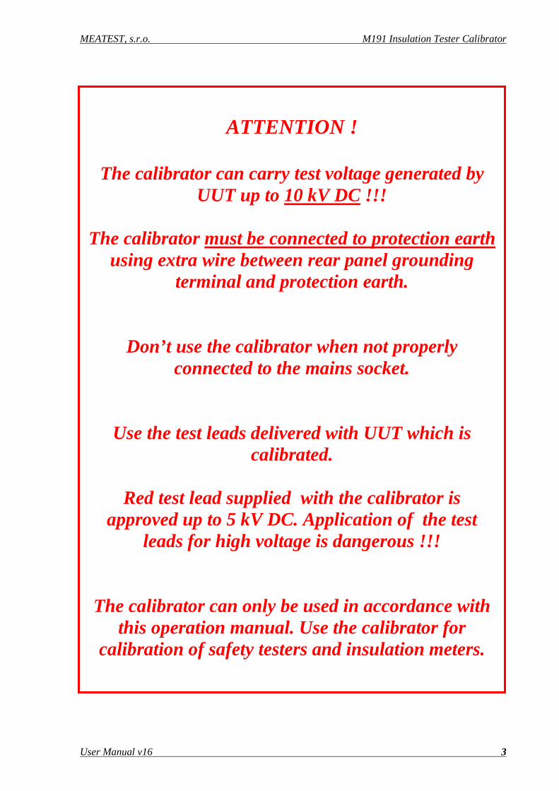
ATTENTION !
The calibrator can carry test voltage generated by UUT up to 10 kV DC !!!
The calibrator must be connected to protection earth
using extra wire between rear panel grounding terminal and protection earth.
Don’t use the calibrator when not properly connected to the mains socket.
Use the test leads delivered with UUT which is calibrated.
Red test lead supplied with the calibrator is
approved up to 5 kV DC. Application of the test leads for high voltage is dangerous !!!
The calibrator can only be used in accordance with this operation manual. Use the calibrator for
calibration of safety testers and insulation meters.
M191 Insulation Tester Calibrator MEATEST, s.r.o.
4 User Manual

MEATEST, s.r.o. M191 Insulation Tester Calibrator
User Manual v16 5
1. Basic Information M191 Insulation tester calibrator is a device designed for application field of calibration of insulation testers. It can be used for calibration of any DC high resistance meter with working voltage up to 10 kV. M191 calibrator is based on programmable high resistance decade which is completed with additional electronic circuits allowing calibration not only resistance ranges, but also calibration of test voltage generated by UUT, testing of short current, verifying of functions of measuring dielectric parameters like polarization index (PI), dielectric absorption ratio (DAR) and polarization ratio (PR). The calibrator enables also verification of timer function of UUTs.
Basic feature of the calibrator is adjustable high resistance decade in summary range from 10 kΩ to 1 TΩ. The decade is designed for operation voltages up to 10 kV. In this range it offers basic accuracy 0.1% to 5 % depending on set resistance value. The calibration can be controlled manually using front panel keypad or in remote mode using one of two types of interfaces GPIB, RS-232 The calibrator can easily fit within calibration systems featuring CALIBER software support.

M191 Insulation Tester Calibrator MEATEST, s.r.o.
6 User Manual
2. Preparation for operation
2.1 Inspecting package contents, selecting the installation location Basic package includes the following items:
• Insulation tester calibrator
• Power cord
• Operation manual
• Test report
• Test cable 5000V / 20A red 1 pc
• Test cable 600V / 19A black 1 pc
• Green/yellow grounding lead 1 pc
• RS232 cable
• Spare fuse T500L250 1 pc
• Spare fuse T1L250 1 pc
Calibrator is packed in doubled cartoon with PE sack. The sack contains silica gel bags to avoid moisture influence during transport and stocking. Leave the cartoon with the calibrator for 24 hours in room temperature before unpacking, especially if during transport the cartoon was exposed temperature lower than 10 ºC.
The calibrator should be powered by 115 V/230 V – 50/60 Hz mains. Before powering on the instruments, place it on a level surface. Do not cover the vents at the bottom side and the fan opening at the rear panel.
2.2 Ambient conditions The calibrator is a laboratory instrument whose parameters are guaranteed at 23±2 oC. For application in full resistance range the relative humidity should not exceed 50 %RH. In resistance range from 10 kΩ to 10 GΩ the calibrator can be applied up to relative humidity to 70 % RH. Accuracy is not guaranteed for operation in relative humidity above 70 %RH.
2.3 Power-on • Before connecting the calibrator to the mains, check the position of the mains voltage selector located at the
rear panel.
• Connect rear panel grounding terminal to protection earth of the mains.
• Plug one end of the power cord into the connector located at the rear panel and connect the other end of the power cord into a wall outlet.
• Connect rear panel grounding post with earthing ground (protection earth) individually using green/yellow grounding lead, see fig. 1.
• Switch on the mains switch located at the rear panel. Front panel display is lit.
• The calibrator performs internal hardware checks for approximately 5 seconds.
• After the tests conclude, the calibrator resets to its reference state, i.e. the following parameters are set:
MEATEST, s.r.o. M191 Insulation Tester Calibrator
User Manual v16 7
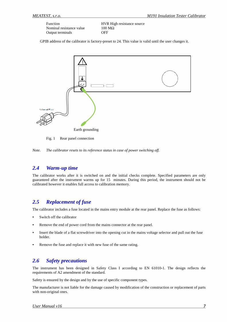
Function HVR High resistance source Nominal resistance value 100 MΩ Output terminals OFF
GPIB address of the calibrator is factory-preset to 24. This value is valid until the user changes it.
Earth grounding Fig. 1 Rear panel connection
Note. The calibrator resets to its reference status in case of power switching off.
2.4 Warm-up time The calibrator works after it is switched on and the initial checks complete. Specified parameters are only guaranteed after the instrument warms up for 15 minutes. During this period, the instrument should not be calibrated however it enables full access to calibration memory.
2.5 Replacement of fuse The calibrator includes a fuse located in the mains entry module at the rear panel. Replace the fuse as follows:
• Switch off the calibrator
• Remove the end of power cord from the mains connector at the rear panel.
• Insert the blade of a flat screwdriver into the opening cut in the mains voltage selector and pull out the fuse holder.
• Remove the fuse and replace it with new fuse of the same rating.
2.6 Safety precautions The instrument has been designed in Safety Class I according to EN 61010-1. The design reflects the requirements of A2 amendment of the standard.
Safety is ensured by the design and by the use of specific component types.
The manufacturer is not liable for the damage caused by modification of the construction or replacement of parts with non-original ones.

M191 Insulation Tester Calibrator MEATEST, s.r.o.
8 User Manual
Safety symbols used on the equipment
Important information. See manual.
Warning - risk of electric shock. Hazardous voltage. Voltage > 30 V DC or AC peak might be present.
Danger - high voltage
Earth ground
MEATEST, s.r.o. M191 Insulation Tester Calibrator
User Manual v16 9
3. Description of controls
3.1 Front panel
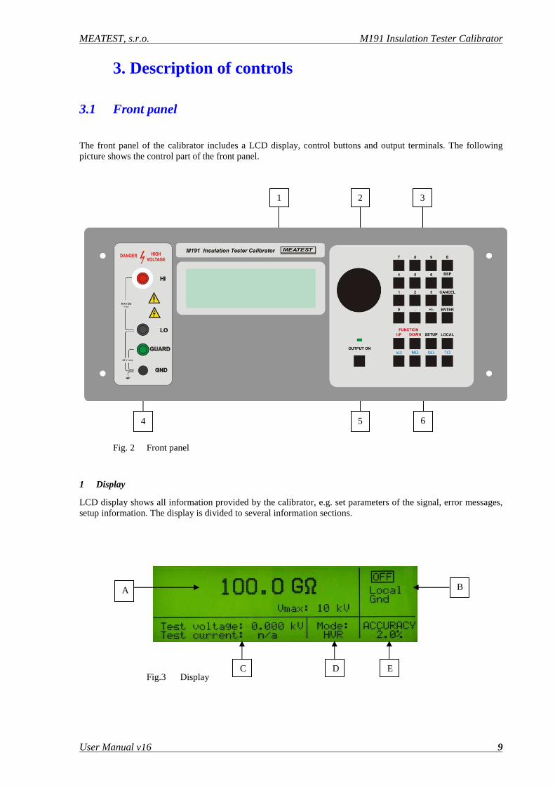
The front panel of the calibrator includes a LCD display, control buttons and output terminals. The following picture shows the control part of the front panel.
Fig. 2 Front panel
1 Display
LCD display shows all information provided by the calibrator, e.g. set parameters of the signal, error messages, setup information. The display is divided to several information sections.
Fig.3 Display
4 5 6
1 2 3
A B
C D E
M191 Insulation Tester Calibrator MEATEST, s.r.o.
10 User Manual
A. Main field. It displays main parameter and limitation for applied test voltage depending on selected function.
B. Information field. It shows status of some parameters:
a. Output terminals status. When OFF sign is displayed the output terminals are disconnected. When sign is displays output terminals are connected.
b. Grounding of L output terminal. When parameter ON is displayed, L output terminal is internally connected to the protection earth (PE wire in power line socket). When parameter is OFF L output terminal is floating. Change of the parameter can be performed in SETUP menu.
Note: Maximum DC voltage between L terminal and GND terminal is 20 VDC. Exceeding the limit can cause damage of the calibrator.
c. Remote/local mode of control.
C. Test signal field. Measured value of current test voltage, resp. current is displayed in the field.
D. Mode indication field. The selected function label is displayed. One of following functions can be selected using FUNCTION UP or FUNCTION DOWN buttons:
a. HVR High resistance source
b. TIMER Timer function of UUT testing
c. SHORT Short current of UUT measuring
d. HVC High voltage capacitance
e. PSP Programmable simulation of polarization/absorption parameters
f. DPP Dielectric and polarization parameters simulator
E. Accuracy field. Actual accuracy of the main parameter is shown in the field.
2 Rotary button
The rotary button enables setting of nominal resistance value. By pushing the knob position marks are displayed. By turning the knob to the left or right, resistance value can be fluently changed up or down.
The central button is used to change between active mark positioning and resistance value setting.
3 Numeric keyboard
The keyboard allows the entry of numeric values on the display. The central button of the rotary button or ENTER button is used to confirm the selection (ENTER). CANCEL button can be used to cancel the entry.
4 Output terminals
Resistance decade box of the calibrator is connected to the output terminals. Meaning of the front panel terminals is as follows:
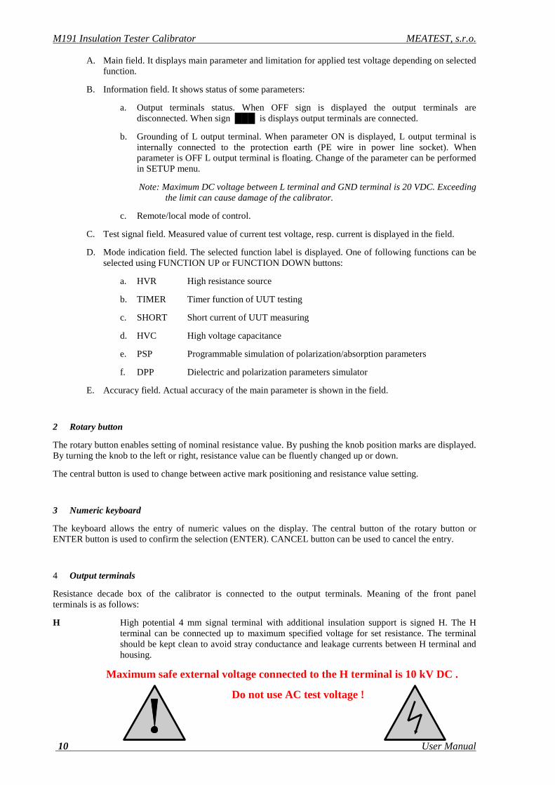
H High potential 4 mm signal terminal with additional insulation support is signed H. The H terminal can be connected up to maximum specified voltage for set resistance. The terminal should be kept clean to avoid stray conductance and leakage currents between H terminal and housing.
Maximum safe external voltage connected to the H terminal is 10 kV DC .
Do not use AC test voltage !
MEATEST, s.r.o. M191 Insulation Tester Calibrator
User Manual v16 11
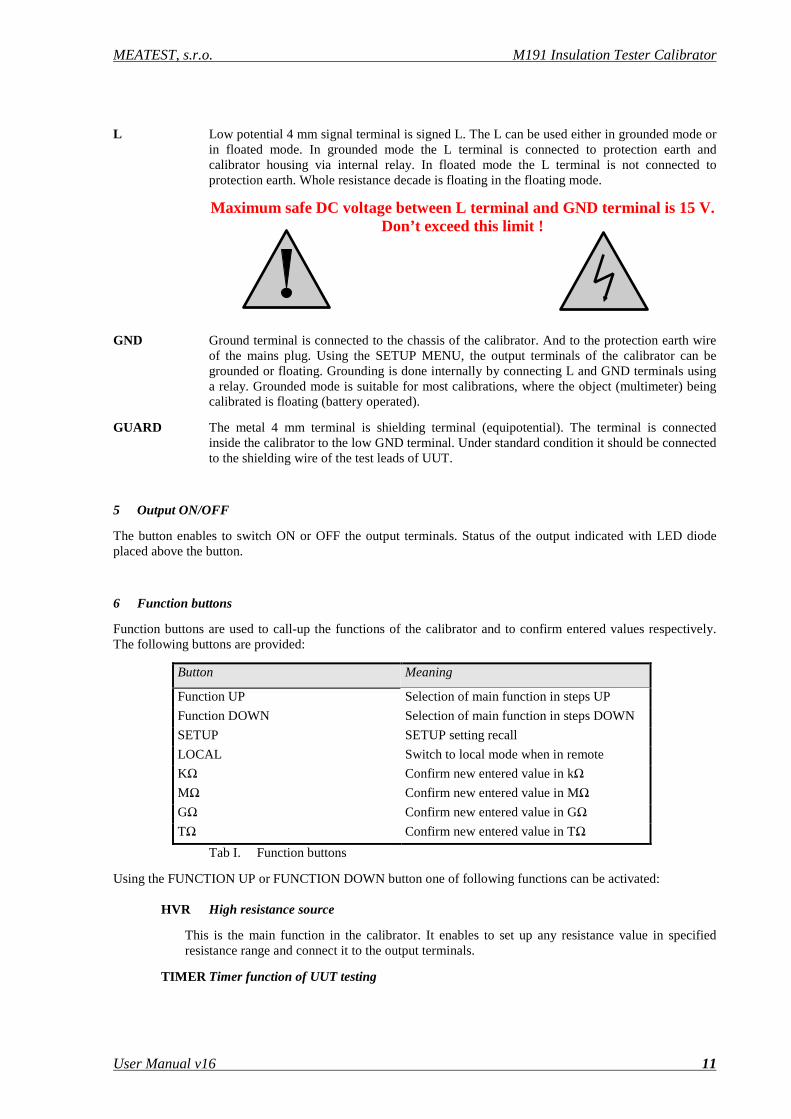
L Low potential 4 mm signal terminal is signed L. The L can be used either in grounded mode or in floated mode. In grounded mode the L terminal is connected to protection earth and calibrator housing via internal relay. In floated mode the L terminal is not connected to protection earth. Whole resistance decade is floating in the floating mode.
Maximum safe DC voltage between L terminal and GND terminal is 15 V. Don’t exceed this limit !
GND Ground terminal is connected to the chassis of the calibrator. And to the protection earth wire of the mains plug. Using the SETUP MENU, the output terminals of the calibrator can be grounded or floating. Grounding is done internally by connecting L and GND terminals using a relay. Grounded mode is suitable for most calibrations, where the object (multimeter) being calibrated is floating (battery operated).
GUARD The metal 4 mm terminal is shielding terminal (equipotential). The terminal is connected inside the calibrator to the low GND terminal. Under standard condition it should be connected to the shielding wire of the test leads of UUT.
5 Output ON/OFF
The button enables to switch ON or OFF the output terminals. Status of the output indicated with LED diode placed above the button.
6 Function buttons
Function buttons are used to call-up the functions of the calibrator and to confirm entered values respectively. The following buttons are provided:
Button Meaning
Function UP Selection of main function in steps UP
Function DOWN Selection of main function in steps DOWN
SETUP SETUP setting recall
LOCAL Switch to local mode when in remote
KΩ Confirm new entered value in kΩ
MΩ Confirm new entered value in MΩ
GΩ Confirm new entered value in GΩ
TΩ Confirm new entered value in TΩ
Tab I. Function buttons
Using the FUNCTION UP or FUNCTION DOWN button one of following functions can be activated:
HVR High resistance source
This is the main function in the calibrator. It enables to set up any resistance value in specified resistance range and connect it to the output terminals.
TIMER Timer function of UUT testing
M191 Insulation Tester Calibrator MEATEST, s.r.o.
12 User Manual
The function is designed to calibrate TIMER function in UUTs, like HIPOT testers,insulation metes, programmable megaohmmeters, etc. Using the function accuracy of time interval in which the UUT test signal is connected to its output terminals can be easily performed.
SHORT Short current of UUT measuring
The function allows measuring of short current supplied by UUT when the output terminals are shorted.
HVC High voltage capacitance
The calibrator contains three high voltage capacitors with nominal vales 10, 50, 100 nF. Using the function capacitance measurement function of UUTs – megaohmmeters can be verified.
DPP Simulator of polarization/absorption parameters
The function can simulate various polarization/absorption indexes often built-in the UUTs. The functions enables to switch over the output resistance in predefined time from one value to another value. In this way the calibrator can simulate the above mentioned parameters.
Following parameters are predefined:
DAR – Dielectric absorption ratio
PI – Polarization index
PR – Polarization ratio
PSP Programmable simulation of polarization/absorption parameters
The function enables to switch over the output resistance in by user predefined time from one value to another. Up to four different resistance values can be step by step connected to the output terminals in selected time intervals.
3.2 Rear panel
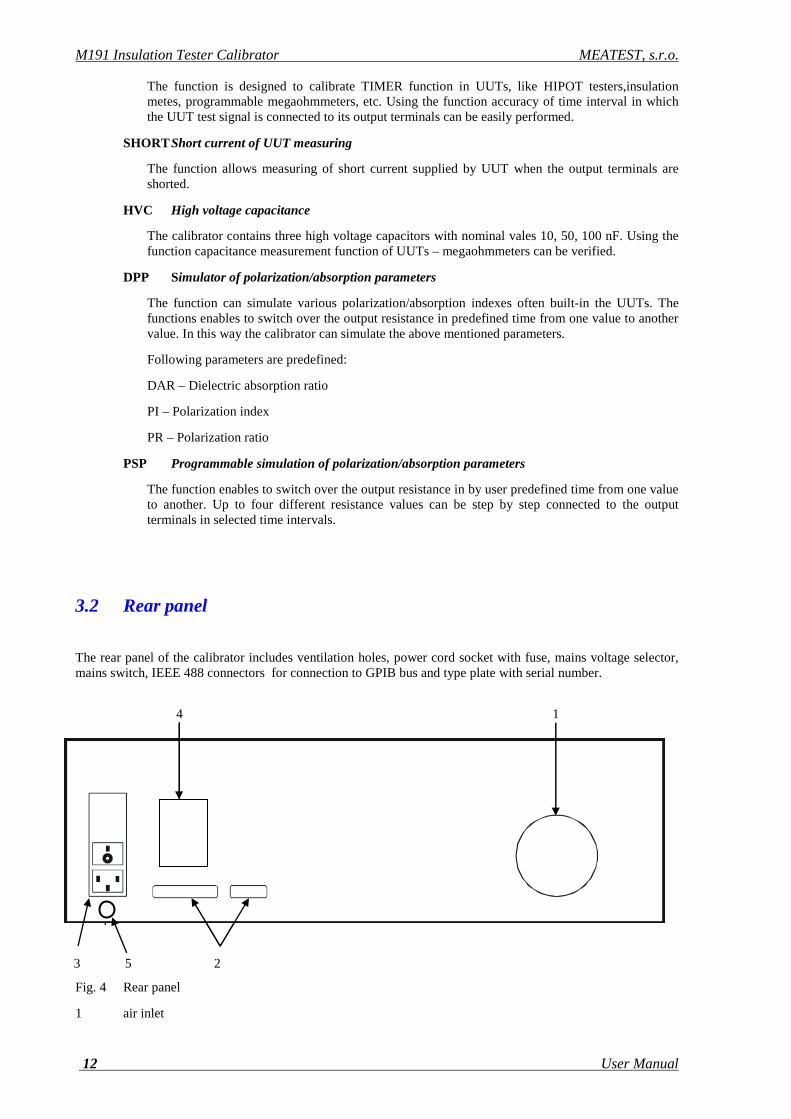
The rear panel of the calibrator includes ventilation holes, power cord socket with fuse, mains voltage selector, mains switch, IEEE 488 connectors for connection to GPIB bus and type plate with serial number.
Fig. 4 Rear panel
1 air inlet
4 1
3 5 2
MEATEST, s.r.o. M191 Insulation Tester Calibrator
User Manual v16 13
2 GPIB, RS-232 connectors 3 power cord socket with fuse, mains voltage selector, mains switch 4 model plate 5 grounding terminal
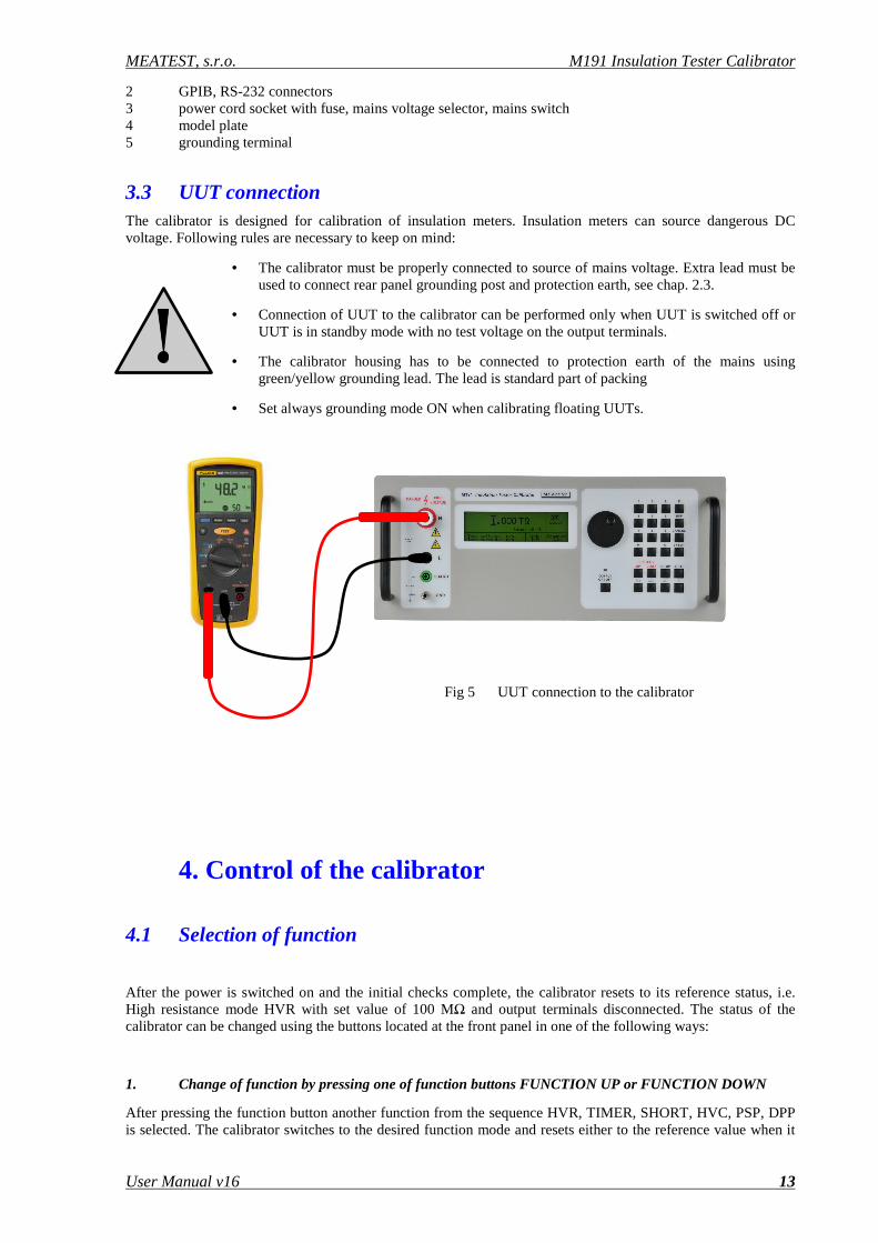
3.3 UUT connection The calibrator is designed for calibration of insulation meters. Insulation meters can source dangerous DC voltage. Following rules are necessary to keep on mind:
• The calibrator must be properly connected to source of mains voltage. Extra lead must be used to connect rear panel grounding post and protection earth, see chap. 2.3.
• Connection of UUT to the calibrator can be performed only when UUT is switched off or UUT is in standby mode with no test voltage on the output terminals.
• The calibrator housing has to be connected to protection earth of the mains using green/yellow grounding lead. The lead is standard part of packing
• Set always grounding mode ON when calibrating floating UUTs.
Fig 5 UUT connection to the calibrator
4. Control of the calibrator
4.1 Selection of function
After the power is switched on and the initial checks complete, the calibrator resets to its reference status, i.e. High resistance mode HVR with set value of 100 MΩ and output terminals disconnected. The status of the calibrator can be changed using the buttons located at the front panel in one of the following ways:
1. Change of function by pressing one of function buttons FUNCTION UP or FUNCTION DOWN
After pressing the function button another function from the sequence HVR, TIMER, SHORT, HVC, PSP, DPP is selected. The calibrator switches to the desired function mode and resets either to the reference value when it
M191 Insulation Tester Calibrator MEATEST, s.r.o.
14 User Manual
is selected the first time after power on or to the most recently used parameter setting when the function have been already selected after power on.
2. Connection /disconnection of output terminals
After pressing the OUTPUT ON button, the output terminals of the calibrator are connected/disconnected. The output on statue is indicated by LED diode above the button and with the sign ON in the right upper corner of the display.
3. Entry to the setup menu
After pressing the SETUP button, options of the SETUP MENU appear on the display. Last item of the SETUP menu is entry to the calibration mode. When selected the calibration mode previous function is restored by pressing of EXIT display button.
4.2 Setting the value
Setting of numerical values in all functions can be made in two ways:
Entry of the value using numeric keyboard
• use the numeric keyboard to select the desired value. After the first digit is entered, symbols of unit of measurements are displayed above the display buttons. The monitor line displays the symbols [ _ _ _ _ _ _ _ _ ].
• after the entry is complete (the value is displayed on the monitor line), press ENTER button or one of quantity buttons kΩ, MΩ, GΩ, TΩ
• the value is copied to the main display and the monitor line disappears.
Entry of the value using the potentiometer
• press the potentiometer knob. The display now includes cursor marks which point to the active digit
• turn the knob to change the active digit
• press the potentiometer knob to change to the mode which allows to change the value of the active digit. ← and → symbols are displayed above the active digit. Active digit can be changed by turning the knob.
• turn the knob to change back to the mode which allows to change the position of the active digit.
• to get to the default screen, keep pressing the center cursor button until there is no [ _ _ _ _ _ _ _ ] under any value, or press EXIT button. All values can be set using the buttons or the potentiometer.
4.3 Connection / disconnection of the output terminals
After switching on the output terminals are disconnected in all modes. Press the OUTPUT button to connect the output signal to the terminals. Green LED above the OUTPUT button is lit and the information field on the display shows the following symbol.
MEATEST, s.r.o. M191 Insulation Tester Calibrator
User Manual v16 15
Press the OUTPUT button again to disconnect the output terminals. Green LED goes off and the information field on the display shows the following symbol .
During function change, output terminals are always disconnected.
4.4 HVR High resistance source mode
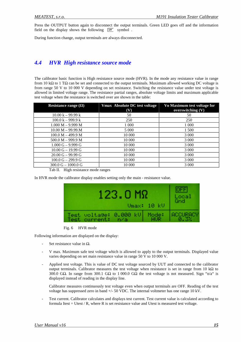
The calibrator basic function is High resistance source mode (HVR). In the mode any resistance value in range from 10 kΩ to 1 TΩ can be set and connected to the output terminals. Maximum allowed working DC voltage is from range 50 V to 10 000 V depending on set resistance. Switching the resistance value under test voltage is allowed in limited voltage range. The resistance partial ranges, absolute voltage limits and maximum applicable test voltage when the resistance is switched over are shown in the table:
Tab II. High resistance mode ranges
In HVR mode the calibrator display enables setting only the main - resistance value.
Fig. 6 HVR mode
Following information are displayed on the display:
- Set resistance value in Ω.
- V max. Maximum safe test voltage which is allowed to apply to the output terminals. Displayed value varies depending on set main resistance value in range 50 V to 10 000 V.
- Applied test voltage. This is value of DC test voltage sourced by UUT and connected to the calibrator output terminals. Calibrator measures the test voltage when resistance is set in range from 10 kΩ to 300.0 GΩ. In range from 300.1 GΩ to 1 000.0 GΩ the test voltage is not measured. Sign “n/a“ is displayed instead of reading in the display line.
Calibrator measures continuously test voltage even when output terminals are OFF. Reading of the test voltage has suppressed zero in band +/- 50 VDC. The internal voltmeter has one range 10 kV.
- Test current. Calibrator calculates and displays test current. Test current value is calculated according to formula Itest = Utest / R, where R is set resistance value and Utest is measured test voltage.
Resistance range (Ω) Vmax Absolute DC test voltage (V)
Vo Maximum test voltage for overswitching (V)
10.00 k – 99.99 k 50 50 100.0 k – 999.9 k 250 250
1.000 M – 9.999 M 1 000 1 000 10.00 M – 99.99.M 5 000 1 500 100.0 M – 499.9 M 10 000 3 000 500.0 M – 999.9 M 10 000 3 000 1.000 G – 9.999 G 10 000 3 000 10.00 G – 19.99 G 10 000 3 000 20.00 G – 99.99 G 10 000 3 000 100.0 G – 299.9 G 10 000 3 000 300.0 G – 1000.0 G 10 000 3 000
M191 Insulation Tester Calibrator MEATEST, s.r.o.
16 User Manual
Test current is displayed only when output terminals are ON. Test current is not displayed when set resistance is higher than 300.0 GΩ.
- Accuracy. Calibrator displays accuracy of selected resistance point in %.
Operating procedure
A. Connect UUT to the output terminals. Use only test leads with guaranteed isolation according to test voltage range of UUT. Use test leads delivered with UUT whenever it is possible.
B. Select HVR mode pushing repeatedly FUNCTION UP or FUNCTION DOWN button until HVR label appears on the display.
C. Enter requested resistance value using either numerical keyboard or rotary button. Confirm the value by pushing the appropriate unit button kΩ, MΩ, GΩ or TΩ.
D. Connect output terminals of the M191 ON by pushing the button OUTPUT ON. Green LED starts to light. M191 starts to measure test voltage and current.
E. Select requested test voltage level in UUT. Select resistance range in UUT if necessary.
F. Activate UUT measurement, typically by pushing ON button on the UUT. UUT starts to source DC test voltage.
G. M191 calibrator measures the test voltage and display both test voltage and current.
H. Compare UUT reading to M191 set resistance.
I. Switch the UUT output OFF to remove test voltage from its output.
J. Disconnect M191 output terminals using the button OUTPUT ON.
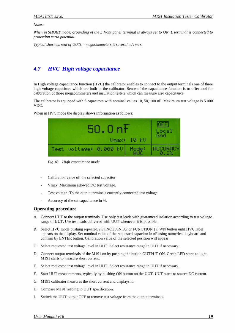
Be aware that the test voltage for high resistance measurements is dangerous and can cause
electric shock!
Notes:
Test leads delivered with the calibrator are approved for application up to 5kVDC. Use test leads delivered with UUTs for higher test voltages.
Don’t change set resistance value when test voltage above Vo is connected to the output terminals, see table II.
Change the resistance value is allowed only when attached test voltage is lower than Vo in Table II. If the test voltage is over Vo and attempt to change the resistance is registered , calibrator does not disconnect the output terminals and shows error message “Err2 Set voltage bellow Vo !”. Setup resistance is not changed. Switch off the test voltage first or decrease its value to level lower than shown in the table II.
Before the output terminals are switched to ON state, calibrator measures test voltage. If the test voltage is higher than the limits in Table II, calibrator does not execute the ON command. Instead of this “Err1 Too high test voltage!” is displayed. Decrease test voltage before continue.
4.5 TIMER Timer function
Timer function allows to verify Timer features of safety testers and megaohmmeters. Calibrator can measure time interval for what the UUT test voltage is presented on the calibrator output terminals. During the measurement the calibrator goes automatically through sequence of statues: OFF, STANDBY, RUNNING, OFF. In Timer function calibrator automatically connects to the output terminals resistance value 100 MΩ. The value cannot be modified.

MEATEST, s.r.o. M191 Insulation Tester Calibrator
User Manual v16 17
Display shows information as follows ( Standby mode):
Fig. 7 Timer mode STANDBY
- Measured time in seconds with 100 ms resolution.
- Vmax parameter is maximum DC test voltage which has been caught by the calibrator during time interval of the Timer calibration.
- Test voltage. Current test voltage presented on the calibrator output terminals during calibration process.
- Accuracy of the measured time interval in s.
Operating procedure
A. Connect UUT to the output terminals. Use only test leads with guaranteed isolation according to test voltage range of UUT. Use test leads delivered with UUT whenever it is possible.
B. Select TIMER mode pushing repeatedly FUNCTION UP or FUNCTION DOWN button until TIMER label appears on the display.
C. Select requested test voltage level in UUT. Select resistance range in UUT if necessary. Select function TIMER in UUT and set-up requested time interval.
D. Switch output terminals of the M191 ON by pushing the button OUTPUT ON. Green LED starts to light. M191 goes over to STANDBY. This statue is signalized with the label in right upper corner of the display. In STANDBY mode the calibrator is waiting for test voltage. Minimum guaranteed valid test voltage which can be caught by the calibrator is 100 VDC.
E. When valid test voltage is identified on the output terminals, the calibrator goes over to RUNNING statue. In this mode calibrator counts time for which the valid test voltage is attached to the output terminals. Calibrator displays current time interval and current test voltage.
F. When the test voltage is disconnected by UUT, calibrator stops operation, goes over to statue OFF, disconnect output terminals and hold value of measured time interval and maximum test voltage which has been detected during the period.
Fig.8 Timer mode OFF
G. Compare M191 time interval reading to on the UUT preset time.
Notes:
Do not disconnect connection between UUT and M191 calibrator otherwise the measured values are not valid.

M191 Insulation Tester Calibrator MEATEST, s.r.o.
18 User Manual
Be aware that the test voltage for high resistance measurements is dangerous and can cause
electric shock!
Test leads delivered with the calibrator are approved for application up to 5kVDC. Use test leads delivered with UUTs for higher test voltages.
4.6 SHORT Short current mode
Short current mode (SHORT) is designed to enable verification of short current capability of UUTs - megaohmmeters. M191 measures DC test current sourced by UUT under short circuit condition. M191 milliampermeter has one range 5 mA with five-digit resolution in this mode. Nominal input resistance is 2.5 kΩ.
Display shows information as follows:
Fig.9 SHORT mode
- Measured short current in mA
- Accuracy of the measured value in %.
Operating procedure
A. Connect UUT to the output terminals. Use only test leads with guaranteed isolation according to test voltage range of UUT. Use test leads delivered with UUT whenever it is possible.
B. Select SHORT mode pushing repeatedly FUNCTION UP or FUNCTION DOWN button until SHORT label appears on the display.
C. Connect output terminals of the M191 ON by pushing the button OUTPUT ON. Green LED starts to light. M191 starts to measure short current.
D. Select requested test voltage level in UUT. Select resistance range in UUT if necessary.
E. Activate UUT measurement, typically by pushing ON button on the UUT. UUT starts to source DC current.
F. M191 calibrator measures the short current and displays it.
G. Compare M191 reading to UUT specification.
H. Switch the UUT output OFF to remove test voltage from the output terminals.
I. Disconnect M191 output terminals using the button OUTPUT ON.
MEATEST, s.r.o. M191 Insulation Tester Calibrator
User Manual v16 19
Notes:
When in SHORT mode, grounding of the L front panel terminal is always set to ON. L terminal is connected to protection earth potential.
Typical short current of UUTs – megaohmmeters is several mA max.
4.7 HVC High voltage capacitance
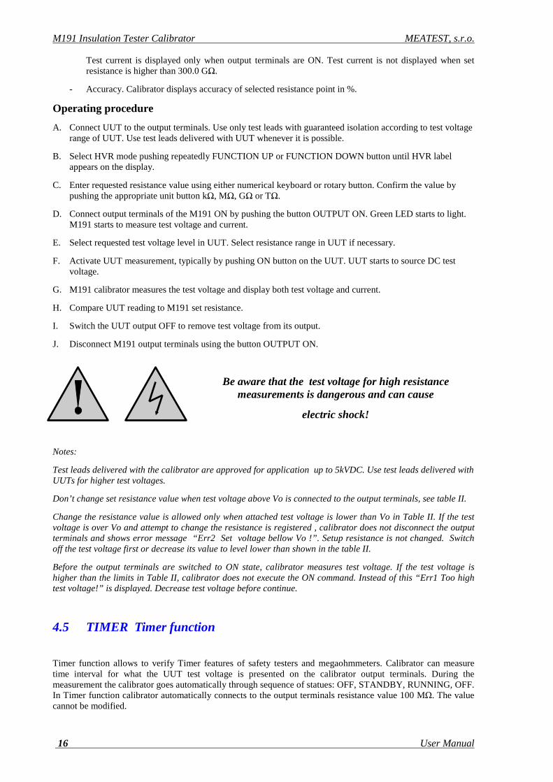
In High voltage capacitance function (HVC) the calibrator enables to connect to the output terminals one of three high voltage capacitors which are built-in the calibrator. Sense of the capacitance function is to offer tool for calibration of those megaohmmeters and insulation testers which can measure also capacitance.
The calibrator is equipped with 3 capacitors with nominal values 10, 50, 100 nF. Maximum test voltage is 5 000 VDC.
When in HVC mode the display shows information as follows:
Fig.10 High capacitance mode
- Calibration value of the selected capacitor
- Vmax. Maximum allowed DC test voltage.
- Test voltage. To the output terminals currently connected test voltage
- Accuracy of the set capacitance in %.
Operating procedure
A. Connect UUT to the output terminals. Use only test leads with guaranteed isolation according to test voltage range of UUT. Use test leads delivered with UUT whenever it is possible.
B. Select HVC mode pushing repeatedly FUNCTION UP or FUNCTION DOWN button until HVC label appears on the display. Set nominal value of the requested capacitor in nF using numerical keyboard and confirm by ENTER button. Calibration value of the selected position will appear.
C. Select requested test voltage level in UUT. Select resistance range in UUT if necessary.
D. Connect output terminals of the M191 on by pushing the button OUTPUT ON. Green LED starts to light. M191 starts to measure short current.
E. Select requested test voltage level in UUT. Select resistance range in UUT if necessary.
F. Start UUT measurements, typically by pushing ON button on the UUT. UUT starts to source DC current.
G. M191 calibrator measures the short current and displays it.
H. Compare M191 reading to UUT specification.
I. Switch the UUT output OFF to remove test voltage from the output terminals.
M191 Insulation Tester Calibrator MEATEST, s.r.o.
20 User Manual
J. Disconnect M191 output terminals using the button OUTPUT ON.
Notes:
The capacitance function is designed for DC applications. AC test voltage is not allowed to apply. When using AC voltage over 100 V the calibrator can be damaged.
The capacitance function is designed for testing of insulation meters and megaohmmeters which can measure the capacitance in test circuit based on charging and discharging the circuit. Any other application is not recommended.
Don’t disconnect test wires when measuring is in process. Disconnection can cause damage of the calibrator.
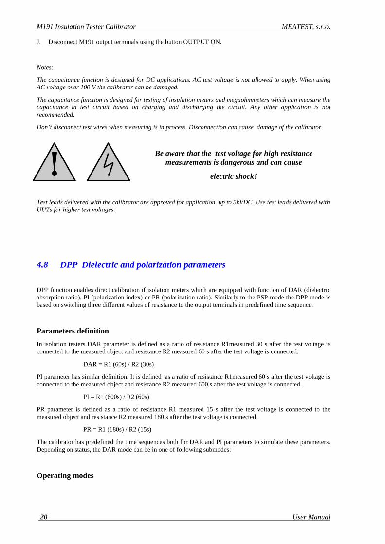
Be aware that the test voltage for high resistance measurements is dangerous and can cause
electric shock!
Test leads delivered with the calibrator are approved for application up to 5kVDC. Use test leads delivered with UUTs for higher test voltages.
4.8 DPP Dielectric and polarization parameters
DPP function enables direct calibration if isolation meters which are equipped with function of DAR (dielectric absorption ratio), PI (polarization index) or PR (polarization ratio). Similarly to the PSP mode the DPP mode is based on switching three different values of resistance to the output terminals in predefined time sequence.
Parameters definition
In isolation testers DAR parameter is defined as a ratio of resistance R1measured 30 s after the test voltage is connected to the measured object and resistance R2 measured 60 s after the test voltage is connected.
DAR = R1 (60s) / R2 (30s)
PI parameter has similar definition. It is defined as a ratio of resistance R1measured 60 s after the test voltage is connected to the measured object and resistance R2 measured 600 s after the test voltage is connected.
PI = R1 (600s) / R2 (60s)
PR parameter is defined as a ratio of resistance R1 measured 15 s after the test voltage is connected to the measured object and resistance R2 measured 180 s after the test voltage is connected.
PR = R1 (180s) / R2 (15s)
The calibrator has predefined the time sequences both for DAR and PI parameters to simulate these parameters. Depending on status, the DAR mode can be in one of following submodes:
Operating modes

MEATEST, s.r.o. M191 Insulation Tester Calibrator
User Manual v16 21
OFF In OFF mode the output terminals are disconnected. Both type of requested parameter, nominal resistance and parameter index can be set.
STANDBY When OUTPUT ON button is pushed, calibrator goes over to STANDBY mode. In this mode is waiting for test voltage from UUT to start simulation sequence. When presence of the test voltage is recognized, calibrator goes over to RUNNING mode.
RUNNING Calibrator simulation sequence has been launched. Calibrator switches the setup resistances to the output terminals in preset time intervals. When the sequence is finished, calibrator stays in RUNNING mode until the output terminals are disconnected using OUTPUT ON/OFF button. During running mode currently applied test voltage and total elapsed time are displayed.
In DPP mode the display shows information as follows (OFF submode):
Fig.11 Programming the DPP mode
Following parameters can be entered:
- PARAMETER field. One defined parameters DAR/PR/PI can be selected.
- R0 parameter. This is the resistance which is connected to the output terminals in STANDBY mode. The parameter range is from 10 MΩ to 100 GΩ.
- DAR/PR/PI coefficient. Requested value of the coefficient which is asked to simulate can be entered. Range of the value is from 0.5 to 99.9. From the entered coefficient and R0 nominal resistance calibrator calculates resistance level which will be connected during RUNNING mode to the output terminals
Following additional parameters are displayed in DAR mode.
- R out value. It is actual resistance value which is currently connected in the RUNNING mode to the output terminals.
- V max parameter 3 kV is maximum applicable test voltage.
- Test voltage. Reading of currently applied DC test voltage is displayed.
- Total time. The time which has been elapsed after the starting RUNNING sequence.
- Accuracy of actually connected resistance in %.
Operating procedure
A. Connect UUT to the output terminals. Use only test leads with guaranteed isolation according to test voltage range of UUT. Use test leads delivered with UUT whenever it is possible.
B. Select DPP mode pushing repeatedly FUNCTION UP or FUNCTION DOWN button until DPP label appears on the display.
C. Use rotary button to select and enter parameter R0, PARAMETER and coefficient. Select requested type of parameter and confirm with ENTER button or rotary button. Write requested resistance value using the numerical keypad and range buttons kΩ, MΩ, GΩ, TΩ and push ENTER button or rotary button to confirm. Write the coefficient and confirm by pushing the ENTER button.
D. When requested parameters are set up, push the OUTPUT ON button. Calibrator connects resistance value R0 to the output terminals and it is waiting for test voltage from UUT. The test voltage must be higher than 100 VDC to start the RUNNING sequence.
M191 Insulation Tester Calibrator MEATEST, s.r.o.
22 User Manual
E. Push START button on UUT. Calibrator recognizes level of active test voltage and executes the preset time sequence procedure. When the procedure is at the end, calibrator stays in RUNNING mode until the output terminals are disconnected using OUTPUT ON/OFF button.
Be aware that the test voltage for high resistance measurements is dangerous and can cause
electric shock!
Notes:
Test leads delivered with the calibrator are approved for application up to 5kVDC. Use test leads delivered with UUTs for higher test voltages.
4.9 PSP Programmable simulation of polarization/absorption
Programmable simulator of polarization PSP mode offers simple calibration and verification of measurement capability of polarization and absorption parameters in isolation testers. The mode is based on programming of time sequence of maximum three various resistances, The preset resistances are step by step connected in predefined time intervals to the output terminals. UUT recognizes change of resistance and evaluates the change of resistance as polarization/absorption parameter.
PSP mode is programmable mode. The resistances connected to the output terminals can be preset in range 1 MΩ to 100 GΩ and can be switched over in programmable time interval up to 9 999 s.
Depending on status, the PSP mode can be in one of following submodes:
OFF In OFF state the time sequence can be programmed, i.e. the time points and resistance values which are to be switched to the output terminals can be set up.
STANDBY Calibrator is waiting in this mode for test voltage from UUT to start simulation sequence. When presence of the test voltage is recognized, calibrator goes over to RUNNING mode.
RUNNING Calibrator simulation sequence has been launched. Calibrator switches the setup resistances to the output terminals in preset time intervals. When the sequence is finished, calibrator stays in RUNNING mode until the output terminals are disconnected using OUTPUT ON/OFF button. During running mode currently applied test voltage and total elapsed time are displayed.
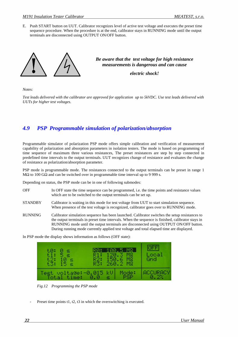
In PSP mode the display shows information as follows (OFF state):
Fig.12 Programming the PSP mode
- Preset time points t1, t2, t3 in which the overswitching is executed.

MEATEST, s.r.o. M191 Insulation Tester Calibrator
User Manual v16 23
- Preset resistances R0, R1, R2, R3 which are connected to the output terminals in time points t0, t1, t2, t3.
- Test voltage. Reading of currently applied DC test voltage is displayed.
- Total time. The time which has been elapsed after the starting RUNNING sequence.
- Accuracy of actually connected resistance in %.
Be aware that the test voltage for high resistance measurements is dangerous and can cause
electric shock!
Notes:
Test leads delivered with the calibrator are approved for application up to 5kVDC. Use test leads delivered with UUTs for higher test voltages.
Time sequence
Following drawing shows meaning and way of influence of the parameters ti and Ri :
Fig.13 Time sequence in PSP mode
Operating procedure
A. Connect UUT to the output terminals. Use only test leads with guaranteed isolation according to test voltage range of UUT. Use test leads delivered with UUT whenever it is possible.
RUNNING mode Test voltage from UUT is identified. Calibrator starts to count time interval t1.
STANDBY mode R1 resistance is selected. Input terminals are switched on. Calibrator is waiting
RUNNING mode Input terminals switched on. R0 resistance is connected. Calibrator counts first time interval t1.
RUNNING mode Input terminals switched on. R2 resistance is connected. Calibrator counts time interval t3.
RUNNING mode Input terminals switched on. R1 resistance is connected. Calibrator counts time interval t2.
t (s)
t3 t2
t1 t0
R (Ω)
RR
R
R
RUNNING mode Input terminals switched on. R3 resistance is connected. Calibrator is in RUNNING mode until output terminlas are disconnected using OUTPUT
M191 Insulation Tester Calibrator MEATEST, s.r.o.
24 User Manual
B. Select PSP mode pushing repeatedly FUNCTION UP or FUNCTION DOWN button until PSP label appears on the display.
C. Use rotary button to select a requested time point t1, t2, t3 or resistance value R0, R1, R2, R3.
D. Write requested time period using the numerical keypad and push ENTER button or rotary button to confirm. Write requested resistance value using the numerical keypad and range buttons kΩ, MΩ, GΩ, TΩ and push ENTER button or rotary button to confirm.
The sequence of parameters t1, t2, t3 and R0, R1, R2, R3 must meet following requirements:
• Maximum value of time interval t1, t2, t3 is lower than 9999 s. Minimum time period value is 1 s.
• Range of R0, R1, R2, R3values is within 10 MΩ and 100 GΩ.
Note: When setting time period and ENTER button or rotary button is pushed two times, time period value is set to OFF position. In OFF position the step is ignored during execution the sequence.
When setting resistance value and ENTER button or rotary button is pushed two times, resistance is set to minimal value 10 kΩ.
E. When requested parameters are set up, push the OUTPUT ON button. Calibrator connects first resistance value R0 to the output terminals and it is waiting for test voltage from UUT. The test voltage must be higher than 100 VDC to start the RUNNING sequence.
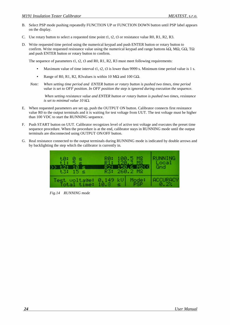
F. Push START button on UUT. Calibrator recognizes level of active test voltage and executes the preset time sequence procedure. When the procedure is at the end, calibrator stays in RUNNING mode until the output terminals are disconnected using OUTPUT ON/OFF button.
G. Real resistance connected to the output terminals during RUNNING mode is indicated by double arrows and by backlighting the step which the calibrator is currently in.
Fig.14 RUNNING mode
MEATEST, s.r.o. M191 Insulation Tester Calibrator
User Manual v16 25
5. Setup menu
The M191 calibrator allows many other, less frequently used parameters to be set. Setup menu is used to set these parameters. Setup menu is opened by pressing SETUP display button. If output terminals are connected, they will be disconnected automatically and the following display appears:
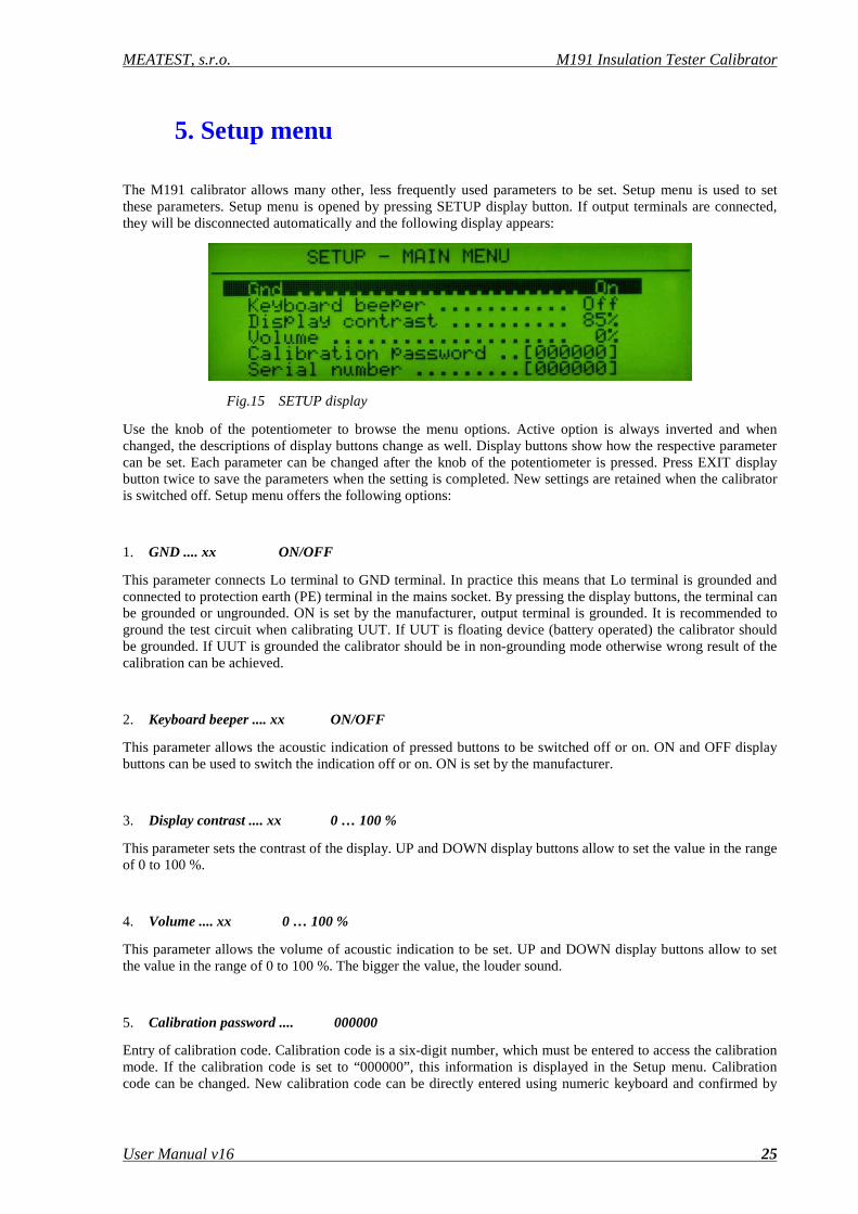
Fig.15 SETUP display
Use the knob of the potentiometer to browse the menu options. Active option is always inverted and when changed, the descriptions of display buttons change as well. Display buttons show how the respective parameter can be set. Each parameter can be changed after the knob of the potentiometer is pressed. Press EXIT display button twice to save the parameters when the setting is completed. New settings are retained when the calibrator is switched off. Setup menu offers the following options:
1. GND .... xx ON/OFF
This parameter connects Lo terminal to GND terminal. In practice this means that Lo terminal is grounded and connected to protection earth (PE) terminal in the mains socket. By pressing the display buttons, the terminal can be grounded or ungrounded. ON is set by the manufacturer, output terminal is grounded. It is recommended to ground the test circuit when calibrating UUT. If UUT is floating device (battery operated) the calibrator should be grounded. If UUT is grounded the calibrator should be in non-grounding mode otherwise wrong result of the calibration can be achieved.
2. Keyboard beeper .... xx ON/OFF
This parameter allows the acoustic indication of pressed buttons to be switched off or on. ON and OFF display buttons can be used to switch the indication off or on. ON is set by the manufacturer.
3. Display contrast .... xx 0 … 100 %
This parameter sets the contrast of the display. UP and DOWN display buttons allow to set the value in the range of 0 to 100 %.
4. Volume .... xx 0 … 100 %
This parameter allows the volume of acoustic indication to be set. UP and DOWN display buttons allow to set the value in the range of 0 to 100 %. The bigger the value, the louder sound.
5. Calibration password .... 000000
Entry of calibration code. Calibration code is a six-digit number, which must be entered to access the calibration mode. If the calibration code is set to “000000”, this information is displayed in the Setup menu. Calibration code can be changed. New calibration code can be directly entered using numeric keyboard and confirmed by
M191 Insulation Tester Calibrator MEATEST, s.r.o.
26 User Manual
pressing ENTER. If non-zero calibration code is set, correct calibration code must be entered to access the calibration mode. Non-zero calibration code is not displayed further on the display.
6. Serial number xxxxxx
Displays the serial number of the calibrator. The parameter cannot be changed.
7. Active interface .... xx GPIB/RS232
Displays the type of interface used to control the calibrator from a PC. By pressing GPIB or RS232 buttons, the respective type can be selected. The calibrator can be remotely controlled only using the selected interface.
8. RS232 baud rate .... xx UP/DOWN
Indicates the communication speed of RS232 bus. UP/DOWN display buttons can be used to select 9600, 19200, 28800, 38400, 57600, 115200. Perfect communication with the PC requires equal values set at the PC and the calibrator.
9. GPIB address .... xx UP/DOWN
Displays the calibrator’s address at the GPIB bus. UP, DOWN display buttons can be used to select any valid GBIP address in the range of 00 to 30. The address 24 is set by the manufacturer.
10. CPU firmware xxxxxx
CPU block firmware version. The parameter cannot be changed.
11. LVR firmware xxxxxx
LVR block firmware version. The parameter cannot be changed.
6. Calibration mode
The M191 calibrator includes a calibration procedure, which allows calibration of the calibrator. Partial resistors of the internal serial resistance decade and calibration points of internal meters can be readjusted during the calibration in predefined order. The calibration can be controlled using the buttons and menu on the calibrator.
Calibration principles
The calibrator can be calibrated:
• completely, i.e. all functions are calibrated in all recommended points
• partially, i.e. only selected functions are calibrated in all recommended points
• partially, i.e. only selected functions are calibrated in selected points
MEATEST, s.r.o. M191 Insulation Tester Calibrator
User Manual v16 27
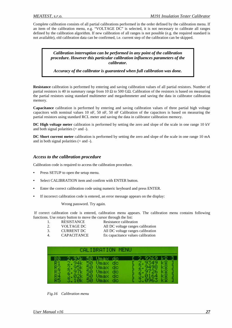
Complete calibration consists of all partial calibrations performed in the order defined by the calibration menu. If an item of the calibration menu, e.g. “VOLTAGE DC” is selected, it is not necessary to calibrate all ranges defined by the calibration algorithm. If new calibration of all ranges is not possible (e.g. the required standard is not available), old calibration data can be confirmed, i.e. current step of the calibration can be skipped.
Resistance calibration is performed by entering and saving calibration values of all partial resistors. Number of partial resistors is 40 in summary range from 10 Ω to 500 GΩ. Calibration of the resistors is based on measuring the partial resistors using standard multimeter and megaohmmeter and saving the data in calibrator calibration memory.
Capacitance calibration is performed by entering and saving calibration values of three partial high voltage capacitors with nominal values 10 nF, 50 nF, 50 nF Calibration of the capacitors is based on measuring the partial resistors using standard RCL meter and saving the data in calibrator calibration memory.
DC High voltage meter calibration is performed by setting the zero and slope of the scale in one range 10 kV and both signal polarities (+ and -).
DC Short current meter calibration is performed by setting the zero and slope of the scale in one range 10 mA and in both signal polarities (+ and -).
Access to the calibration procedure
Calibration code is required to access the calibration procedure.
• Press SETUP to open the setup menu.
• Select CALIBRATION item and confirm with ENTER button.
• Enter the correct calibration code using numeric keyboard and press ENTER.
• If incorrect calibration code is entered, an error message appears on the display:
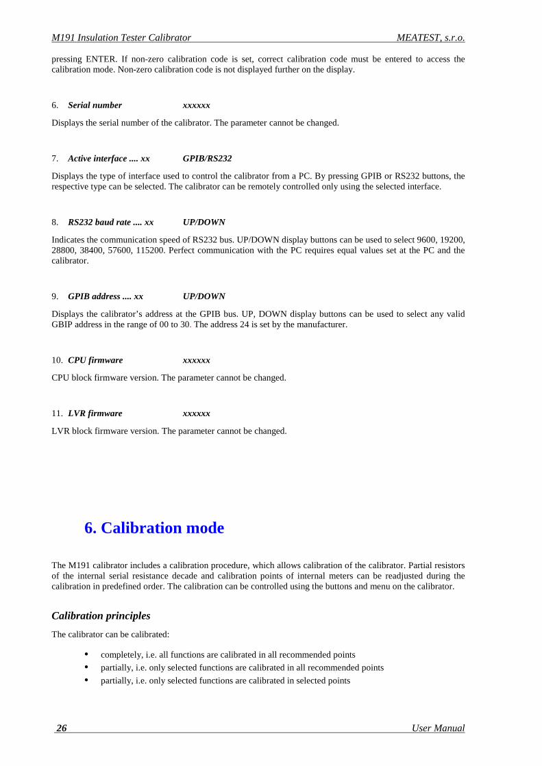
Wrong password. Try again. If correct calibration code is entered, calibration menu appears. The calibration menu contains following functions. Use rotary button to move the cursor through the list: 1. RESISTANCE Resistance calibration
2. VOLTAGE DC All DC voltage ranges calibration 3. CURRENT DC All DC voltage ranges calibration 4. CAPACITANCE fix capacitance values calibration
Fig.16 Calibration menu
Calibration interruption can be performed in any point of the calibration procedure. However this particular calibration influences parameters of the
calibrator.
Accuracy of the calibrator is guaranteed when full calibration was done.

M191 Insulation Tester Calibrator MEATEST, s.r.o.
28 User Manual
Selection and setting of calibration point
After the calibration menu is displayed, one of partial calibrations can be selected. Use rotary button to move the cursor through the list. Having selected the required function to be calibrated, press the rotary button or ENTER button to enable the calibration value in right column for editing. Output terminals are automatically switched on at the same time ready for measuring the selected calibration point.
• Measure the resistance value using standard ohmmeter when resistance segment is calibrated and write down new resistance value. Confirm with ENTER button or rotary button.
• Connect RCL standard meter when capacitance calibration point is to being calibrated and write down new resistance value. Confirm with ENTER button or rotary button.
• When built in kV-meter is calibrated, connect DC voltage of requested value from standard unit and confirm with ENTER button or rotary button to save new calibration data.
• When built in mA-meter is calibrated, connect DC current of requested value from standard unit and confirm with ENTER button or rotary button to save new calibration data.
Go on to next requested calibration point.
When no change of the calibration value is requested push the rotary button of ENTER button once more. The original calibration value is refreshed.
Both complete and partial calibration is possible. When only some calibration points are changed, all other non-changed calibration points are stored with original data. New calibration value is saved immediately when ENTER button or rotary button is pushed for new value confirmation.
Calibration process can be interrupted or left any time by pushing the button SETUP. Calibrator returns to the last selected function.
Note: When resistance points are calibrated two-terminals way of connection of the calibrator to standard ohmmeter should be applied.
Input resistance of internal mA-meter is approx. 2.5 kΩ. Standard current source with compliance voltage min. 15V has to be applied.
Calibration points
Each function of the calibrator has assigned fixed calibration points which have to be set during the calibration. List of calibration points includes:
• Single resistance segments in summary range from 3 kΩ to 1TΩ, R00 to R45
• Single capacitors 10, 50, 100 nF, C00 to C02
• DC voltage 5000 V, V00 and V01
• DC current 5 mA, I00 and I01
MEATEST, s.r.o. M191 Insulation Tester Calibrator
User Manual v16 29
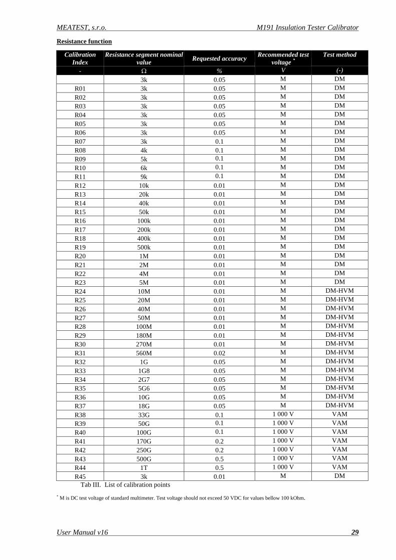
Resistance function
Calibration Index
Resistance segment nominal value
Requested accuracy Recommended test
voltage * Test method
- Ω % V (-)
3k 0.05 M DM
R01 3k 0.05 M DM
R02 3k 0.05 M DM
R03 3k 0.05 M DM
R04 3k 0.05 M DM
R05 3k 0.05 M DM
R06 3k 0.05 M DM
R07 3k 0.1 M DM
R08 4k 0.1 M DM
R09 5k 0.1 M DM
R10 6k 0.1 M DM
R11 9k 0.1 M DM
R12 10k 0.01 M DM
R13 20k 0.01 M DM
R14 40k 0.01 M DM
R15 50k 0.01 M DM
R16 100k 0.01 M DM
R17 200k 0.01 M DM
R18 400k 0.01 M DM
R19 500k 0.01 M DM
R20 1M 0.01 M DM
R21 2M 0.01 M DM
R22 4M 0.01 M DM
R23 5M 0.01 M DM
R24 10M 0.01 M DM-HVM
R25 20M 0.01 M DM-HVM
R26 40M 0.01 M DM-HVM
R27 50M 0.01 M DM-HVM
R28 100M 0.01 M DM-HVM
R29 180M 0.01 M DM-HVM
R30 270M 0.01 M DM-HVM
R31 560M 0.02 M DM-HVM
R32 1G 0.05 M DM-HVM
R33 1G8 0.05 M DM-HVM
R34 2G7 0.05 M DM-HVM
R35 5G6 0.05 M DM-HVM
R36 10G 0.05 M DM-HVM
R37 18G 0.05 M DM-HVM
R38 33G 0.1 1 000 V VAM
R39 50G 0.1 1 000 V VAM
R40 100G 0.1 1 000 V VAM
R41 170G 0.2 1 000 V VAM
R42 250G 0.2 1 000 V VAM
R43 500G 0.5 1 000 V VAM
R44 1T 0.5 1 000 V VAM
R45 3k 0.01 M DM Tab III. List of calibration points
* M is DC test voltage of standard multimeter. Test voltage should not exceed 50 VDC for values bellow 100 kOhm.

M191 Insulation Tester Calibrator MEATEST, s.r.o.
30 User Manual
Voltage, current and capacitance function
Calibration Index Meaning Calibration point Requested accuracy Test method
- -
V00 Zero range 10 kV 0.0 VDC 0.2 V DM-PC
V01 Slope range 10 kV 5 000 VDC 10 V DM-PC
I00 Zero range 5mA 0.000 mA 5 uA DM-PC
I01 Slope range 5mA 5.000 mA 10 uA DM-PC
C00 10 nF capacitor 10.000 nF 20 pF RCL
C01 50 nF capacitor 50.000 nF 100 pF RCL
C02 100nF capacitor 100.00 nF 200 pF RCL Tab IV List of calibration points
DM … direct measurement using standard multimeter, two wire connection. DC test voltage is given by standard multimeter for positions R00 to R37.
DM-HVM … direct measurement using standard multimeter, two wire connection, high voltage mode.
VAM … Volt-amper method using multifunction calibrator and uA-meter
DM-PC … direct measurement using standard process calibrator
RCL … direct measurement using standard RCL meter, test frequency 100 Hz, test voltage 1V
Full calibration procedure
Following pages describe procedure of the full calibration.
Required instruments:
Following instruments are required for calibration:
• 81/2 digit multimeter type Fluke 8508A or similar with 0.01 % accuracy and range to 20 GΩ.
• 81/2 digit multimeter Agilent 3458A or pA-meter Keithley 2635A or similar with DC current range 100 nA to 10 mA
• RLC meter Agilent 4263A, Agilent 4278A, or other with accuracy 0.1 %
• Multifunction calibrator Meatest M-140, M142, Fluke 5500A or similar with DC voltage range to 1000 V.
• Process calibrator Burster 4423, Fluke 745A or similar with DC current range to 10 mA and accuracy 0.1%.
• DC High voltage source Heinzinger PNC-10000 or similar with output voltage accuracy 0.2%.
Calibration procedure
1. Connect the calibrator and the multimeter to the mains and let them switched on for at least 30 minutes in a laboratory at 23±1 oC and RH < 50 %.
2. Press SETUP display button to call up the setup menu. Select item GND and switch it to ON.
3. Select CALIBRATION MENU item.
4. Enter the calibration code and press ENTER (default calibration code is “000000”).
MEATEST, s.r.o. M191 Insulation Tester Calibrator
User Manual v16 31
5. Resistance calibration
Direct measurement using standard multimeter
a) Connect the input terminals of the standard multimeter to the H - L output terminals of the calibrator. Use two wire connection. Set standard multimeter to resistance mode, 5-digit resolution
b) Select first partial resistance segment R00 by pushing the rotary button or ENTER button. Read the resistance value indicated by standard multimeter and write down the value to the calibrator using numerical keypad. Confirm by pushing the rotary button or ENTER button.
c) Continue in calibration of next resistance segments up to position R37. Use the same system as in previous step.
Non-direct measurement using volt-amper method
d) Disconnect standard multimeter.
e) Push the SETUP button to exit the calibration mode. Select item GND and switch it to OFF.
f) Enter again calibration mode.
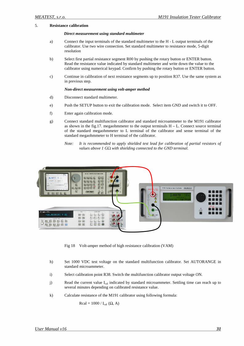
g) Connect standard multifunction calibrator and standard microammeter to the M191 calibrator as shown in the fig.17. megaohmmeter to the output terminals H – L. Connect source terminal of the standard megaohmmeter to L terminal of the calibrator and sense terminal of the standard megaohmmeter to H terminal of the calibrator.
Note: It is recommended to apply shielded test lead for calibration of partial resistors of values above 1 GΩ with shielding connected to the GND terminal.
Fig 18 Volt-amper method of high resistance calibration (VAM)
h) Set 1000 VDC test voltage on the standard multifunction calibrator. Set AUTORANGE in standard microammeter.
i) Select calibration point R38. Switch the multifunction calibrator output voltage ON.
j) Read the current value Ical indicated by standard microammeter. Settling time can reach up to several minutes depending on calibrated resistance value.
k) Calculate resistance of the M191 calibrator using following formula:
Rcal = 1000 / Ical (Ω, A)

M191 Insulation Tester Calibrator MEATEST, s.r.o.
32 User Manual
l) Write down the value to the calibrator using numerical keypad. Confirm by pushing the rotary button or ENTER button.
m) Continue in calibration of next resistance segments up to position R44. Use the same system as in previous step.
n) Disconnect multifunction calibrator and standard microammeter.
o) Push the SETUP button to exit the calibration mode. Select item GND and switch it to ON.
p) Enter again calibration mode.
q) Connect standard d multimeter again to the output terminals H – L.
r) Measure resistance segment R45, write it down to the calibrator and confirm by ENTER button.
6. DC voltage calibration
a) Make short terminal between H and L terminals. Select position V00 from the list of calibration points.
b) Live readings in bits of the calibrator built in kV-meter can be seen in right column. Push the rotary button or ENTER button to save new calibration value.
c) Disconnect short wire and connect output of multifunction calibrator. Set DC voltage, 5000 V on it.
d) Switch on the standard calibrator output terminals. Live readings in bits can be seen on M191 calibrator right column. Push the rotary button or ENTER button to save new calibration value.
e) Switch off the multifunction calibrator output terminals. Disconnect the terminals.
7. DC current calibration
a) Make short terminal between H and L terminals. Select position I00 from the list of calibration points.
b) Live readings in bits of the calibrator built in mA-meter can be seen in right column. Push the rotary button or ENTER button to save new calibration value.
c) Disconnect short wire and connect output of process calibrator. Set DC current, 5 mA on it.
d) Switch on the process calibrator output terminals. Live readings in bits can be seen on M191 calibrator right column. Push the rotary button or ENTER button to save new calibration value.
e) Switch off the process calibrator output terminals. Disconnect the terminals.
8. Capacitance calibration
a) Connect to the H – L terminals standard RCL meter. Select test frequency 100 Hz.
b) Select calibration point C00. Measure the capacitor, write down the value and confirm with ENTER or rotary button.
c) Continue in calibration of next capacitance segments C01, C02. Use the same system as in previous step
d) Disconnect the terminals.
9. Push the SETUP button to exit the calibration mode. Calibration has been performed.
MEATEST, s.r.o. M191 Insulation Tester Calibrator
User Manual v16 33
7. Verification procedure
Procedure recommended for verifying parameters of the calibrator is described in this chapter.
Required equipment
Following instruments are required for calibration:
* 81/2 digit multimeter type Fluke 8508A or similar with 0.01 % accuracy and range to 20 GΩ.
* 81/2 digit multimeter Agilent 3458A or pA-meter Keithley 2635A or similar with DC current range 100 nA to 10 mA
* RLC meter Agilent 4263A, Agilent 4278A, or other with accuracy 0.1 %
* Multifunction calibrator Meatest M-140, M142, Fluke 5500A or similar with DC voltage range to 1000 V.
* Process calibrator Burster 4423, Fluke 745A or similar with DC current range to 10 mA and accuracy better than 0.1%.
* DC High voltage source Heinzinger PNC-10000 or similar with output voltage accuracy 0.2%.
Configuration of the calibrator
Calibrator should be tested directly from the front panel terminals. Performance verification may be performed after warm-up period i.e. 15 minutes after switching on. Calibrator have to be in temperature stabilize condition at minimum 8 hours before performance verification test is started.
Basic steps of the performance verification test
Verification procedure consists of following steps:
• High resistance decade resistors in range from 10 kΩ to 1 TΩ
• DC voltage in ranges to 10 kV
• DC current in range to 5 mA
• Capacitance test in points 10n, 50n, 100nF
Procedure
Following part describes procedure of performance verification test. Recommended test points including applied method specification and allowed limits are shown in table Tab V.
Resistance verification
1. Connect the calibrator to the mains and let them switched on for at least one 15minutes in a laboratory at 23±1 oC.
2. Connect calibrator output to standard multimeter of type according to the table Tab V, select function of ohmmeter.
3. Set resistance values 10kΩ to 100 kΩ in the calibrator. Check reading of the standard multimeter and compare with limits in the table Tab V.
M191 Insulation Tester Calibrator MEATEST, s.r.o.
34 User Manual
4. Select function High-ohm in standard multimeter. Set resistance values 200kΩ to 10 GΩ in the calibrator. Check reading of the standard multimeter and compare with limits in the table Tab V.
5. Disconnect standard multimeter. Connect multifunction calibrator and standard multimeter according to the table Tab V, see fig. 18. Select function ADC in the standard multimeter and set 1000VDC in standard multifunction calibrator.
6. Set resistance values 20 GΩ to 100 GΩ in the calibrator. Calculate measured resistance according to formula: R = 1000/I where I is standard multimeter reading. Compare with the limits in the table Tab V.
7. Connect DC High voltage source instead of multifunction calibrator according to the table Tab V. Set recommended DC voltage 5000V or 1000VDC according to the table Tab V. If necessary, check DC output voltage using standard DC voltage divider and standard voltmeter.
8. Set resistance values 200GΩ, 500GΩ, 10 MΩ, 100MΩ, 1GΩ, 10GΩ, 100GΩ, 1TΩ according to the table V. Calculate measured resistance according to formula: R = U/I where I is standard multimeter reading and U is output voltage of the DC High voltage source. Compare with the limits in the table Tab V.
DC voltage verification
9. Disconnect standard multimeter. Connect DC High voltage source directly to H – L output terminals of the M191 calibrator.
10. Set DC output voltage according to table Tab V. Compare M191 calibrator DC voltage indication with min/max limits in the table Tab V. If necessary, check DC output voltage using standard DC voltage divider and standard voltmeter to improve accuracy of the source.
DC current verification
11. Connect process calibrator to the H – L M191 output terminals, set DCI function. Set function SHORT in M191 calibrator.
12. Set DC current values in the process calibrator according to the table Tab V. Compare reading of the DC current indicated by M191 calibrator with min/max limits in the table Tab V.
Capacitance verification
13. Connect standard RCL meter to the H – L M191 output terminals, set tset frequency 120 Hz. Set function HVC in M191 calibrator.
14. Set capacitance values according to the table Tab V. Compare reading of the RCL meter with min/max limits in the table Tab V.

MEATEST, s.r.o. M191 Insulation Tester Calibrator
User Manual v16 35
Function
Range
Nominal
value
Standard unit
Parameter
Test method
Limit min
Limit max
HVR 100kΩ 10kΩ Fluke 8508A <10V DM 9.98kΩ 10.02kΩ HVR 100kΩ 20kΩ Fluke 8508A <10V DM 19.96kΩ 20.04kΩ HVR 100kΩ 40kΩ Fluke 8508A <10V DM 39.92kΩ 40.08kΩ HVR 100kΩ 80kΩ Fluke 8508A <10V DM 79.84kΩ 80.16kΩ HVR 100kΩ 100kΩ Fluke 8508A <10V DM 99.9kΩ 100.1kΩ HVR 1MΩ 200kΩ Fluke 8508A <10V DM-HVM 199.8kΩ 200.2kΩ HVR 1MΩ 400kΩ Fluke 8508A <10V DM-HVM 399.6kΩ 400.4kΩ HVR 1MΩ 800kΩ Fluke 8508A <10V DM-HVM 799.2kΩ 800.8kΩ HVR 1MΩ 1MΩ Fluke 8508A < 250V DM-HVM 0.999MΩ 1.001MΩ HVR 10MΩ 2MΩ Fluke 8508A < 250V DM-HVM 1.998MΩ 2.002MΩ HVR 10MΩ 4MΩ Fluke 8508A < 250V DM-HVM 3.996MΩ 4.004MΩ HVR 10MΩ 8MΩ Fluke 8508A < 250V DM-HVM 7.992MΩ 8.008MΩ HVR 10MΩ 10MΩ Fluke 8508A < 250V DM-HVM 9.99MΩ 10.01MΩ HVR 100MΩ 20MΩ Fluke 8508A < 250V DM-HVM 19.98MΩ 20.02MΩ HVR 100MΩ 40MΩ Fluke 8508A < 250V DM-HVM 39.96MΩ 40.04MΩ HVR 100MΩ 80MΩ Fluke 8508A < 250V DM-HVM 79.92MΩ 80.08MΩ
HVR 100MΩ 100MΩ Fluke 8508A < 250V DM-HVM 99.9MΩ 100.1MΩ
HVR 1GΩ 200MΩ Fluke 8508A < 250V DM-HVM 199.8MΩ 200.2MΩ HVR 1GΩ 400MΩ Fluke 8508A < 250V DM-HVM 399.6MΩ 400.4MΩ HVR 1GΩ 800MΩ Fluke 8508A < 250V DM-HVM 798.4MΩ 801.6MΩ HVR 1GΩ 1GΩ Fluke 8508A < 250V DM-HVM 0.995GΩ 1.005GΩ HVR 10GΩ 2GΩ Fluke 8508A < 250V DM-HVM 1.990GΩ 2.010GΩ HVR 10GΩ 4GΩ Fluke 8508A < 250V DM-HVM 3.980GΩ 4.020GΩ
HVR 10GΩ 8GΩ Fluke 8508A < 250V DM-HVM 7.960GΩ 8.040GΩ HVR 10GΩ 10GΩ Fluke 8508A < 250V DM-HVM 9.95GΩ 10.05GΩ HVR 100GΩ 20GΩ Multifunction
calibrator M140+multimeter
HP3458A
1000V VAM
19.8GΩ 20.2GΩ
HVR 100GΩ 40GΩ Multifunction calibrator
M140+multimeter HP3458A
1000V VAM 39.6GΩ 40.4GΩ
HVR 100GΩ 80GΩ Multifunction calibrator
M140+multimeter HP3458A
1000V VAM 79.2GΩ 80.8GΩ
HVR 100GΩ 100GΩ Multifunction calibrator
M140+multimeter HP3458A
1000V VAM 98.0GΩ 102.0GΩ
HVR 1TΩ 200GΩ DC High voltage source + multimeter
HP3458A
5000V VAM 196.0GΩ 204.0GΩ
HVR 1TΩ 500GΩ DC High voltage source + multimeter
HP3458A
5000V VAM 475GΩ 525GΩ
HVR 10MΩ 10MΩ DC High voltage source + multimeter
HP3458A
5000V VAM 9.99MΩ 10.01MΩ
HVR 100MΩ 100MΩ DC High voltage 10000V VAM 99.9MΩ 100.1MΩ

M191 Insulation Tester Calibrator MEATEST, s.r.o.
36 User Manual
source + multimeter HP3458A
HVR 1GΩ 1GΩ DC High voltage source + multimeter
HP3458A
10000V VAM 0.995GΩ 1.005GΩ
HVR 10GΩ 10GΩ DC High voltage source + multimeter
HP3458A
10000V VAM 9.95GΩ 10.05GΩ
HVR 100GΩ 100GΩ DC High voltage source + multimeter
HP3458A
10000V VAM 98.0GΩ 102.0GΩ
HVR 1TΩ 1TΩ DC High voltage source + multimeter
HP3458A
10000V VAM 0.95TΩ 1.05TΩ
DCV 10000V 500V DC High voltage source + multimeter
HP3458A + standard DC
voltage divider
100MΩ DM 487.5V 512.5V
DCV 10000V 1000V DC High voltage source + multimeter
HP3458A + standard DC
voltage divider
100MΩ DM 985V 1015V
DCV 10000V 2000V DC High voltage source + multimeter
HP3458A + standard DC
voltage divider
100MΩ DM 1980V 2020V
DCV 10000V 4000V DC High voltage source + multimeter
HP3458A + standard DC
voltage divider
100MΩ DM 3970V 4030V
DCV 10000V 10000V DC High voltage source + multimeter
HP3458A + standard DC
voltage divider
100MΩ DM 9940V 10060V
DCI 5mA 1mA Process calibrator DM-PC 0.993mA 1.007mA DCI 5mA 2mA Process calibrator DM-PC 1.991mA 2.009mA DCI 5mA 5mA Process calibrator DM-PC 4.985mA 5.015mA C 10nF 10nF RCL meter F = 120 Hz DM CV-30pF CV+30pF C 50nF 50nF RCL meter F = 120 Hz DM CV-
150pF CV+150pF
C 100nF 100nF RCL meter F = 120 Hz DM CV-300pF
CV+300pF
Tab V Verification test
DM … direct measurement using standard multimeter, two wire connection. DC test voltage is given by standard multimeter for positions R00 to R37.
DM-HVM … direct measurement using standard multimeter, two wire connection, high voltage mode.
VAM … Volt-amper method using multifunction calibrator and uA-meter
DM-PC … direct measurement using standard process calibrator
RCL … direct measurement using standard RCL meter, test frequency 100 Hz, test voltage 1V
CV … calibration value of the capacitance
MEATEST, s.r.o. M191 Insulation Tester Calibrator
User Manual v16 37
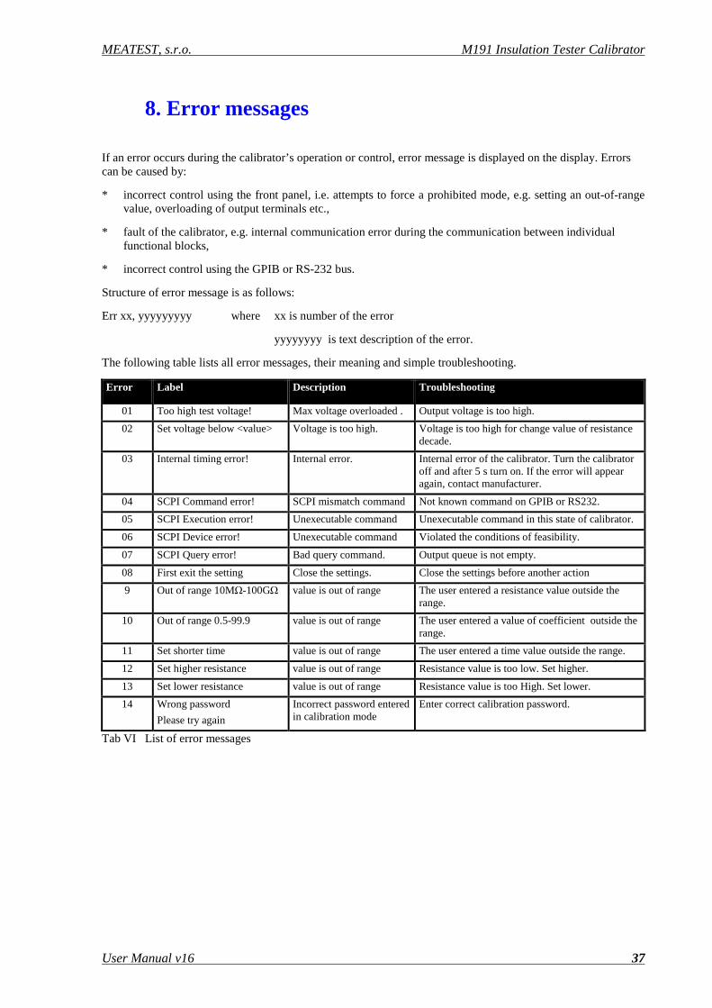
8. Error messages
If an error occurs during the calibrator’s operation or control, error message is displayed on the display. Errors can be caused by:
* incorrect control using the front panel, i.e. attempts to force a prohibited mode, e.g. setting an out-of-range value, overloading of output terminals etc.,
* fault of the calibrator, e.g. internal communication error during the communication between individual functional blocks,
* incorrect control using the GPIB or RS-232 bus.
Structure of error message is as follows:
Err xx, yyyyyyyyy where xx is number of the error
yyyyyyyy is text description of the error.
The following table lists all error messages, their meaning and simple troubleshooting.
Error Label Description Troubleshooting
01 Too high test voltage! Max voltage overloaded . Output voltage is too high.
02 Set voltage below <value> Voltage is too high. Voltage is too high for change value of resistance decade.
03 Internal timing error! Internal error. Internal error of the calibrator. Turn the calibrator off and after 5 s turn on. If the error will appear again, contact manufacturer.
04 SCPI Command error! SCPI mismatch command Not known command on GPIB or RS232.
05 SCPI Execution error! Unexecutable command Unexecutable command in this state of calibrator.
06 SCPI Device error! Unexecutable command Violated the conditions of feasibility.
07 SCPI Query error! Bad query command. Output queue is not empty.
08 First exit the setting Close the settings. Close the settings before another action
9 Out of range 10MΩ-100GΩ value is out of range The user entered a resistance value outside the range.
10 Out of range 0.5-99.9 value is out of range The user entered a value of coefficient outside the range.
11 Set shorter time value is out of range The user entered a time value outside the range.
12 Set higher resistance value is out of range Resistance value is too low. Set higher.
13 Set lower resistance value is out of range Resistance value is too High. Set lower.
14 Wrong password
Please try again
Incorrect password entered in calibration mode
Enter correct calibration password.
Tab VI List of error messages
M191 Insulation Tester Calibrator MEATEST, s.r.o.
38 User Manual
9. Calibrator maintenance
The multifunction calibrator is electronic instrument with microprocessor control. All blocks which are heavily loaded during the operation are cooled by a fan.
Rules for correct operation
Especially the following rules should be adhered to guarantee correct operation of the calibrator:
• The calibrator can only be switched on and off by pressing the mains switch located at the rear panel.
• Do not connect the calibrator to other voltage than set by the voltage selector.
• Do not block the vent openings located at the rear panel and bottom panel.
• The calibrator must not be operated in dusty or wet environment. It was designed to be used in a laboratory.
• No liquid or small objects can be permitted to enter the calibrator through the vent openings..
• Do not switch the calibrator outside its operating temperature range.
• Connect the instruments to be calibrated to proper output terminals. There is no way of protecting the calibrator from the damage caused by some improper connections.
• Do not damage the output terminals by plugging in “bananas” thicker than the terminals were designed for.
• Whenever possible, use the setup menu to ground L output terminal (GND ON setup function).
Regular maintenance
The calibrator does not require any special maintenance of electrical or mechanical parts. If is gets dirty, the case and the display can be cleaned by a wool rag moistened with alcohol.
The calibrator should be calibrated in the recommended 12-month intervals. A calibration center equipped for high resistance measurement should perform the calibration.
What to do in case of failure If an obvious failure occurs during the operation (e.g. the display is not lit, the fan is not turning), the calibrator must be switched off immediately. First, check the fuse located in the power cord receptacle. Procedure is following:
* Remove the end of power cord from the mains connector at the rear panel.
* Insert the blade of a flat screwdriver into the opening cut in the mains voltage selector and pry out the fuse holder.
• Remove the fuse. Replace it with new fuse of the same rating if the fuse was broken.
• Replace the fuse holder, reconnect the power cord and switch on the calibrator. If the problem persists, contact the manufacturer.
MEATEST, s.r.o. M191 Insulation Tester Calibrator
User Manual v16 39
If an obvious fault is evidenced, e.g. a measurement range or an operating mode is not functional, the user cannot correct the fault. Contact the manufacturer.
Hidden faults can cause different symptoms and be caused by different causes. Usually, they cause instability of some parameter. Hidden defects can be caused by unacceptable distortion, degraded insulation etc. In this case contact the manufacturer.
Sometimes it seems that the calibrator has hidden defect, when the rules for correct operation are not adhered to. In this case, the fault is caused by the operator. Most frequent cases of false “hidden defects”:
• mains voltage out of tolerance limits or unstable
• wrong grounding of the measurement circuit (bad connection of the ground terminal of the mains outlet, or several ground connection when grounding loops are formed)
• proximity to sources of intensive influence, whose products are spread through the mains or propagated by the electromagnetic field
• strong electrostatic or electromagnetic field which can cause major instability during calibration using higher impedance.

M191 Insulation Tester Calibrator MEATEST, s.r.o.
40 User Manual
10. System control
The calibrator includes standardized IEEE-488 bus and RS232 serial line. System connectors are located at the rear panel. For the remote control to work properly, bus parameters must be set in the system menu. For IEEE-488 bus, address is important (0 to 30 setting range). For RS232 bus, communication speed can be set (9600 to 115200 Bd). The calibrator can be only controlled by one interface at a time. It is therefore necessary to select one of the interfaces (GPIB/RS232) using the system menu.
9.1 IEEE-488 bus properties
The instrument performs the following functions based on GPIB bus commands:
SH1, AH1, T5, L3, RL1, DC1, SR1
The instrument also recognizes the following general commands:
DCL Device Clear SDC Selected Device Clear EOI End or Identify Message Terminator GTL Go To Local LLO Local Lock Out SPD Serial Poll Disable SPE Serial Poll Enable
Fig 17 GPIB connector
9.2 RS232 bus properties To transfer the data using RS232 bus, 8N1 data format is used, i.e. each data word includes 8 bits, no parity and one stop bit. The communication speed can be set using the system menu. Available values: 9600, 19200, 28800, 38400, 57600 and 115200 Bd
RS-232 connector layout
Pin Label Direction Note
2 TXD output transmitter
3 RXD input receiver
5 GND - ground
Tab VII RS232 connector
Fig 18 9-pin connector D-SUB MALE Cable between the calibrator and PC (configuration 1:1)
PC D-Sub 1 D-Sub 2 M-140 Receiver 2 2 Transmitter Transmitter 3 3 Receiver Ground 5 5 Ground Tab VIII RS232 cable description

MEATEST, s.r.o. M191 Insulation Tester Calibrator
User Manual v16 41
9.3 Command syntax The commands described in this chapter can be issued through both buses (IEEE-488 and RS232).
All commands listed in this chapter are explained in two columns: Command and Description.
Command column includes the name of the command. Each command includes one or more keywords. If a keyword is in brackets ( [ ] ), it is not mandatory. Non-mandatory commands are used only to achieve compatibility with language standard SCPI.
Capitals designate the abbreviated form of the commands; extended form is written in lowercase.
Command parameters are in brackets (<>); each parameter is separated using a comma. Parameters in brackets ( [ ] ) are not mandatory. Line ( | ) means “or” and is used to separate several alternative parameters.
Semicolon ‘;’ is used to separate more commands written on one line. E.g. HVR 10E+6 ; OUTP ON
Note: Each command must end in <cr> or <lf>. Both codes <crlf> can be used at the same time. The calibrator performs all commands written on one line of the program after it receives <cr>, <lf> or <crlf> code. Without this code, the program line is ignored.
Description of Abbreviations
Abbreviation Description
<DNPD>
Decimal Numeric Program Data. This format is used to express decimal number with or without the exponent.
<CPD>
Character Program Data. Usually it represents a group of alternative character parameters. E.g. ON | OFF | 0 | 1.
?
A flag indicating a request for the value of the parameter specified by the command. No parameter other than the question mark can be used.
(?)
A flag indicating a request for the parameter specified by the command. This command permits a value to be set as well as used a request.
<cr> Carriage return. ASCII code 13. This code executes the program line. <lf> Line feed. ASCII code 10. This code executes the program line.
Tab IX Abbreviation description SCPI OUTPut Command Summary
Command Description OUTPut[:STATe]? Returns the state of the output terminals. OUTPut[:STATe]ON|OFF Activates or deactivates output terminals .
Tab X SCPI Output commands

M191 Insulation Tester Calibrator MEATEST, s.r.o.
42 User Manual
SOURce Command Summary
Command Description [SOURce] Path to SOURCE subsystem. :MODE? Returns mode the Calibrator is set to. :HVResistance Sets Calibrator to HVR mode. [:LEVel] <DNPD> Sets the resistance value for HVR mode
:VOLTatge? Returns the measured voltage on the open output terminals.
:CURRent? Returns the current flowing through the selected resistor.
[:LEVel]? Returns the set value for the HVR mode. :TIMer Sets Calibrator to TIM mode. [:LEVel]? Returns the set value for the Timer mode.
:VOLTatge? Returns the measured voltage on the open output terminals.
:SHORt Sets Calibrator to SHORT mode. :CURRent? Returns the current. : HVCapacitance Sets Calibrator to HVC mode. [:LEVel] <CPD> Sets the capacitance value for HVC mode
:VOLTatge? Returns the measured voltage on the open output terminals.
[:LEVel]? Returns the set value for the HVC mode.
: PSPolarization Sets Calibrator to Programable simulator of polarization mode.
:TOTaltime? Returns the measured total time.
:VOLTatge? Returns the measured voltage on the open output terminals.
:RESistance0 <DNPD> Sets the resistance value R0 for PSP mode. :RESistance0? Returns the resistance value R0 for the PSP mode. :RESistance1<DNPD> Sets the resistance value R1 for PSP mode. :RESistance1? Returns the resistance value R1 for the PSP mode. :RESistance2<DNPD> Sets the resistance value R2 for PSP mode. :RESistance2? Returns the resistance value R2 for the PSP mode. :RESistance3<DNPD> Sets the resistance value R3 for PSP mode. :RESistance3? Returns the resistance value R3 for the PSP mode. :TTIMe1 <DNPD> Sets the time value T1 for PSP mode. :TTIMe1? Returns the time value T1 for the PSP mode. :TTIMe2 <DNPD> Sets the time value T2 for PSP mode. :TTIMe2? Returns the time value T2 for the PSP mode. :TTIMe3 <DNPD> Sets the time value T3 for PSP mode. :TTIMe3 ? Returns the time value T3 for the PSP mode.
: DPParameters Sets Calibrator to Dielectric and polarization parameters mode.
:RESistance0<DNPD> Sets the resistance value R0 for DAR mode. :RESistance0? Returns the resistance value R0 for the DPP mode. :CDARatio <DNPD> Sets the DAR coefficient for DPP mode. :CDARatio? Returns the coefficient of DAR value for the DPP mode. :CPIndex <DNPD> Sets the PI coefficient for DPP mode. :CPIndex? Returns the coefficient of PI value for the DPP mode. :CPRatio <DNPD> Sets the PR coefficient for DPP mode. :CPRatio? Returns the coefficient of PR value for the DPP mode. :ROUTput? Returns the actual output resistance for the DPP mode.
:RCOunt? Returns the conted resistance value R0*coefficient for the DPP mode.
:VOLTatge? Returns the measured voltage on the open output terminals.
:TOTaltime? Returns the measured total time.
Tab XI SCPI Source commands
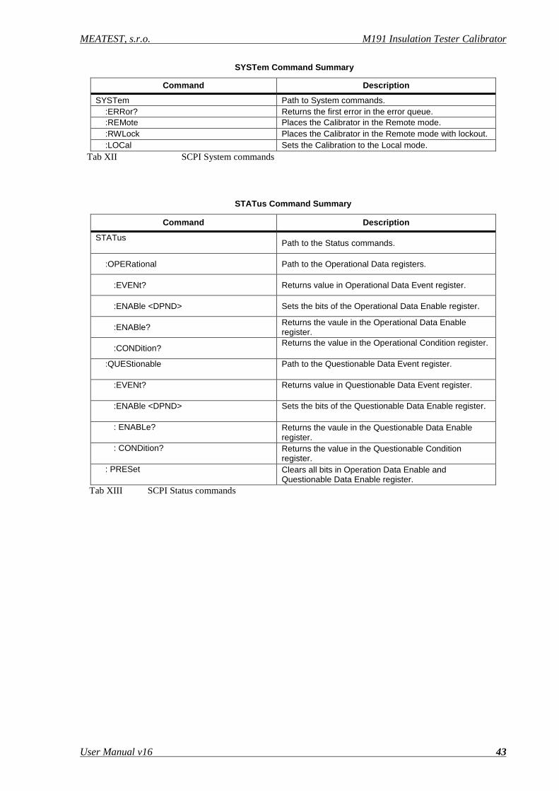
MEATEST, s.r.o. M191 Insulation Tester Calibrator
User Manual v16 43
SYSTem Command Summary
Command Description
SYSTem Path to System commands. :ERRor? Returns the first error in the error queue. :REMote Places the Calibrator in the Remote mode. :RWLock Places the Calibrator in the Remote mode with lockout. :LOCal Sets the Calibration to the Local mode.
Tab XII SCPI System commands
STATus Command Summary
Command Description
STATus Path to the Status commands.
:OPERational Path to the Operational Data registers.
:EVENt? Returns value in Operational Data Event register.
:ENABle <DPND> Sets the bits of the Operational Data Enable register.
:ENABle? Returns the vaule in the Operational Data Enable register.
:CONDition? Returns the value in the Operational Condition register.
:QUEStionable
Path to the Questionable Data Event register.
:EVENt?
Returns value in Questionable Data Event register.
:ENABle <DPND>
Sets the bits of the Questionable Data Enable register.
: ENABLe?
Returns the vaule in the Questionable Data Enable register.
: CONDition?
Returns the value in the Questionable Condition register.
: PRESet
Clears all bits in Operation Data Enable and Questionable Data Enable register.
Tab XIII SCPI Status commands
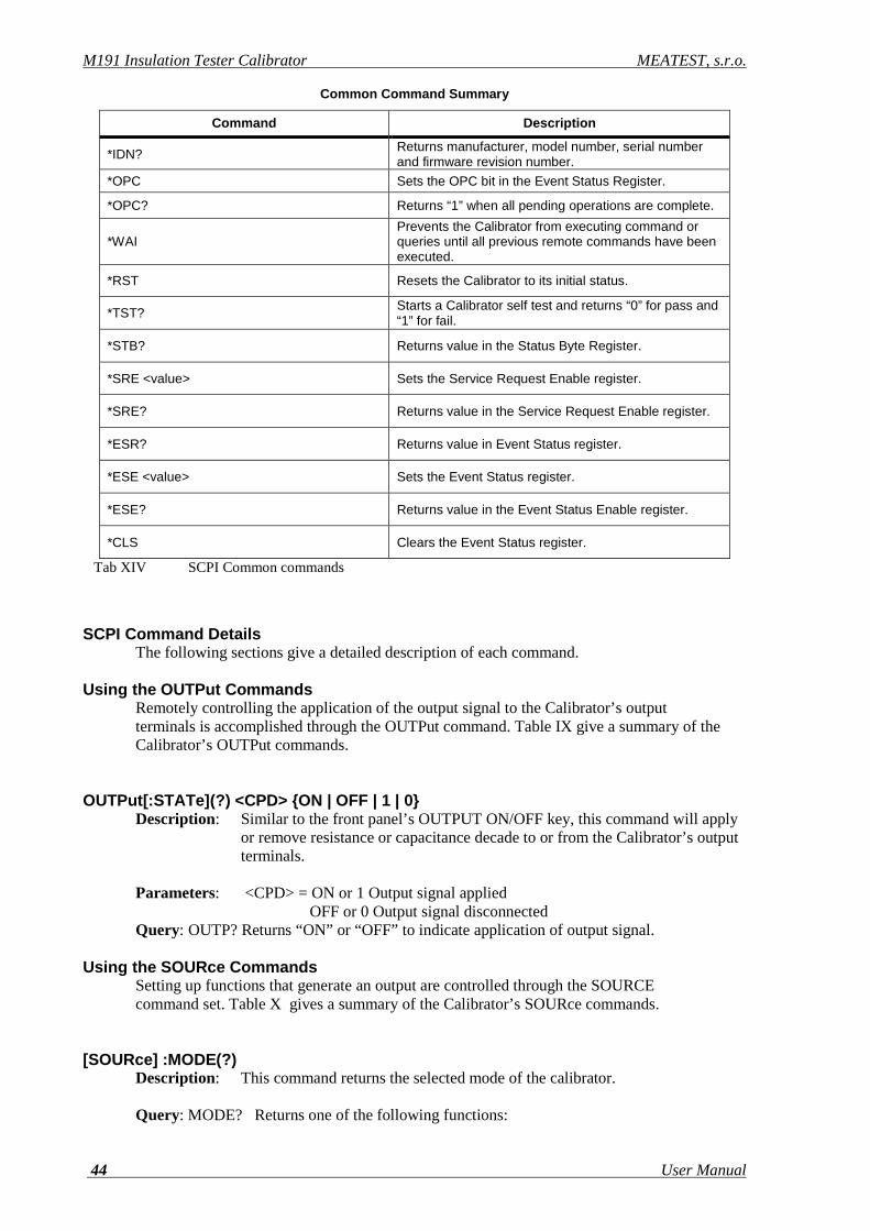
M191 Insulation Tester Calibrator MEATEST, s.r.o.
44 User Manual
Common Command Summary
Command Description
*IDN? Returns manufacturer, model number, serial number and firmware revision number.
*OPC Sets the OPC bit in the Event Status Register.
*OPC? Returns “1” when all pending operations are complete.
*WAI Prevents the Calibrator from executing command or queries until all previous remote commands have been executed.
*RST Resets the Calibrator to its initial status.
*TST? Starts a Calibrator self test and returns “0” for pass and “1” for fail.
*STB? Returns value in the Status Byte Register.
*SRE <value> Sets the Service Request Enable register.
*SRE? Returns value in the Service Request Enable register.
*ESR? Returns value in Event Status register.
*ESE <value> Sets the Event Status register.
*ESE? Returns value in the Event Status Enable register.
*CLS Clears the Event Status register.
Tab XIV SCPI Common commands
SCPI Command Details The following sections give a detailed description of each command. Using the OUTPut Commands Remotely controlling the application of the output signal to the Calibrator’s output terminals is accomplished through the OUTPut command. Table IX give a summary of the Calibrator’s OUTPut commands. OUTPut[:STATe](?) <CPD> ON | OFF | 1 | 0 Description: Similar to the front panel’s OUTPUT ON/OFF key, this command will apply or remove resistance or capacitance decade to or from the Calibrator’s output terminals. Parameters: <CPD> = ON or 1 Output signal applied OFF or 0 Output signal disconnected Query: OUTP? Returns “ON” or “OFF” to indicate application of output signal. Using the SOURce Commands Setting up functions that generate an output are controlled through the SOURCE command set. Table X gives a summary of the Calibrator’s SOURce commands. [SOURce] :MODE(?) Description: This command returns the selected mode of the calibrator. Query: MODE? Returns one of the following functions:
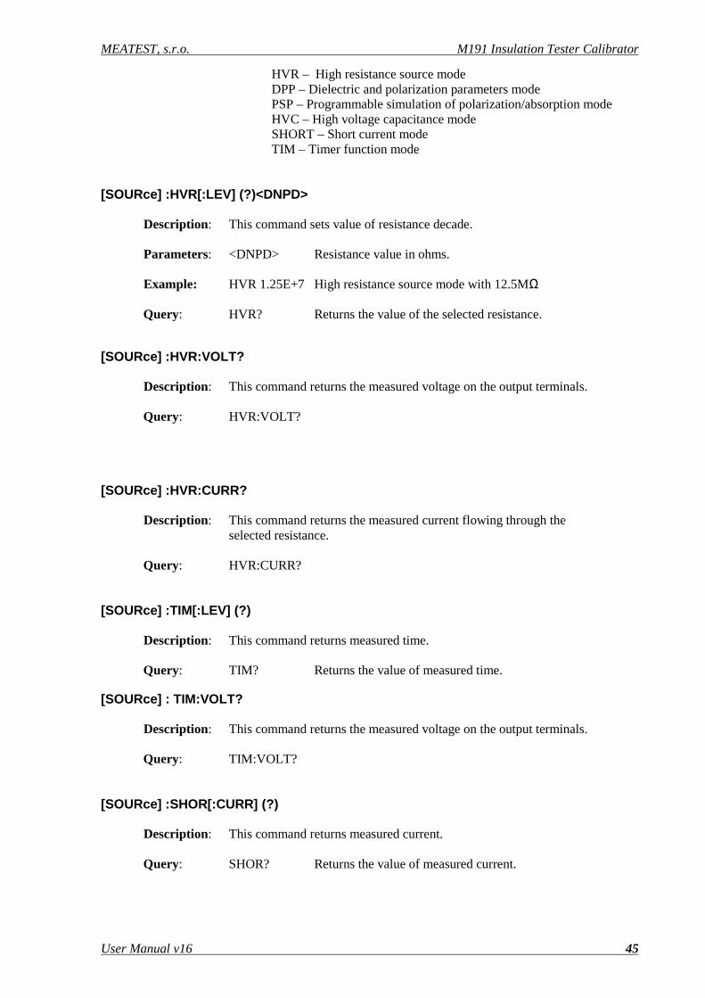
MEATEST, s.r.o. M191 Insulation Tester Calibrator
User Manual v16 45
HVR – High resistance source mode DPP – Dielectric and polarization parameters mode PSP – Programmable simulation of polarization/absorption mode HVC – High voltage capacitance mode SHORT – Short current mode TIM – Timer function mode [SOURce] :HVR[:LEV] (?)<DNPD> Description: This command sets value of resistance decade. Parameters: <DNPD> Resistance value in ohms. Example: HVR 1.25E+7 High resistance source mode with 12.5MΩ Query: HVR? Returns the value of the selected resistance. [SOURce] :HVR:VOLT? Description: This command returns the measured voltage on the output terminals. Query: HVR:VOLT? [SOURce] :HVR:CURR? Description: This command returns the measured current flowing through the selected resistance. Query: HVR:CURR? [SOURce] :TIM[:LEV] (?) Description: This command returns measured time. Query: TIM? Returns the value of measured time. [SOURce] : TIM:VOLT? Description: This command returns the measured voltage on the output terminals. Query: TIM:VOLT? [SOURce] :SHOR[:CURR] (?) Description: This command returns measured current. Query: SHOR? Returns the value of measured current.
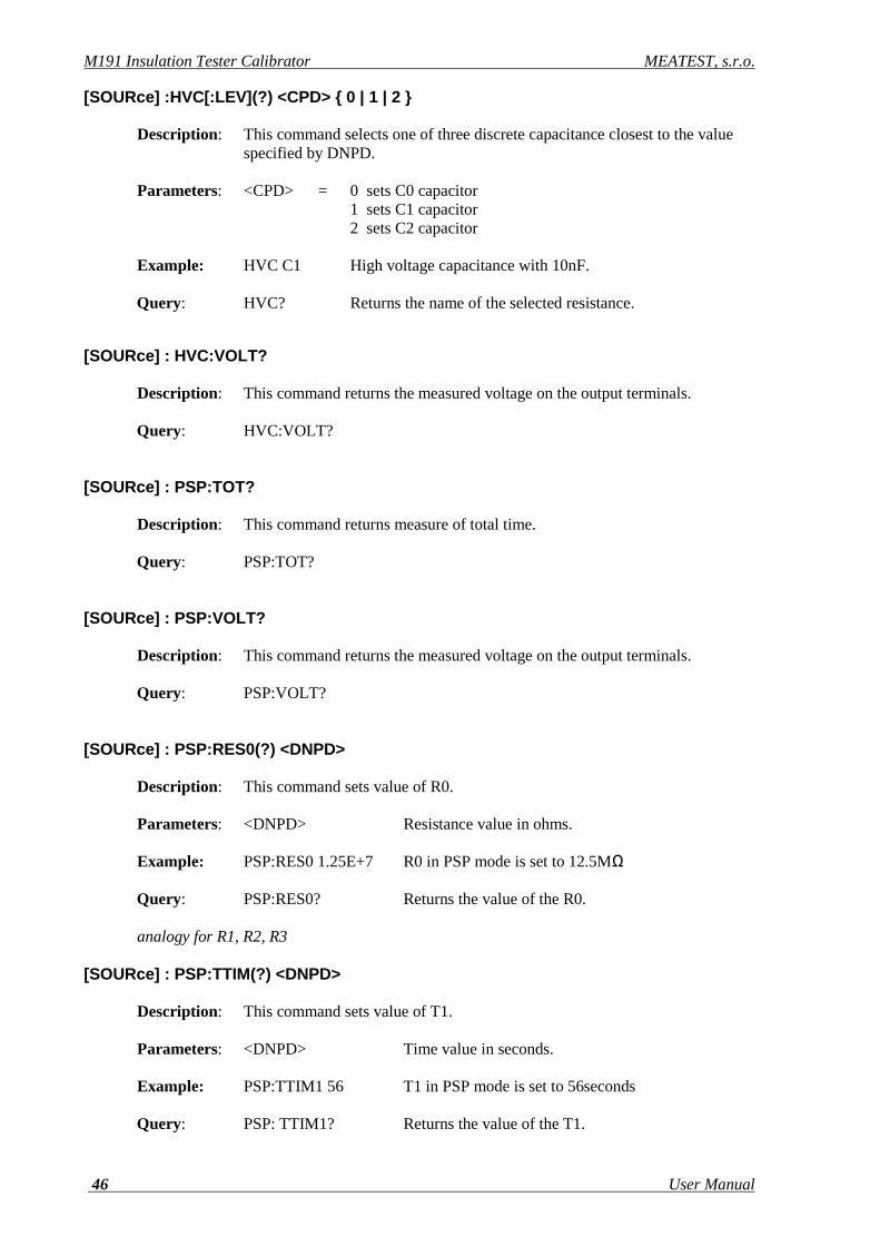
M191 Insulation Tester Calibrator MEATEST, s.r.o.
46 User Manual
[SOURce] :HVC[:LEV](?) <CPD> 0 | 1 | 2 Description: This command selects one of three discrete capacitance closest to the value specified by DNPD. Parameters: <CPD> = 0 sets C0 capacitor 1 sets C1 capacitor 2 sets C2 capacitor Example: HVC C1 High voltage capacitance with 10nF. Query: HVC? Returns the name of the selected resistance. [SOURce] : HVC:VOLT? Description: This command returns the measured voltage on the output terminals. Query: HVC:VOLT? [SOURce] : PSP:TOT? Description: This command returns measure of total time. Query: PSP:TOT? [SOURce] : PSP:VOLT? Description: This command returns the measured voltage on the output terminals. Query: PSP:VOLT? [SOURce] : PSP:RES0(?) <DNPD> Description: This command sets value of R0. Parameters: <DNPD> Resistance value in ohms. Example: PSP:RES0 1.25E+7 R0 in PSP mode is set to 12.5MΩ Query: PSP:RES0? Returns the value of the R0. analogy for R1, R2, R3 [SOURce] : PSP:TTIM(?) <DNPD> Description: This command sets value of T1. Parameters: <DNPD> Time value in seconds. Example: PSP:TTIM1 56 T1 in PSP mode is set to 56seconds Query: PSP: TTIM1? Returns the value of the T1.
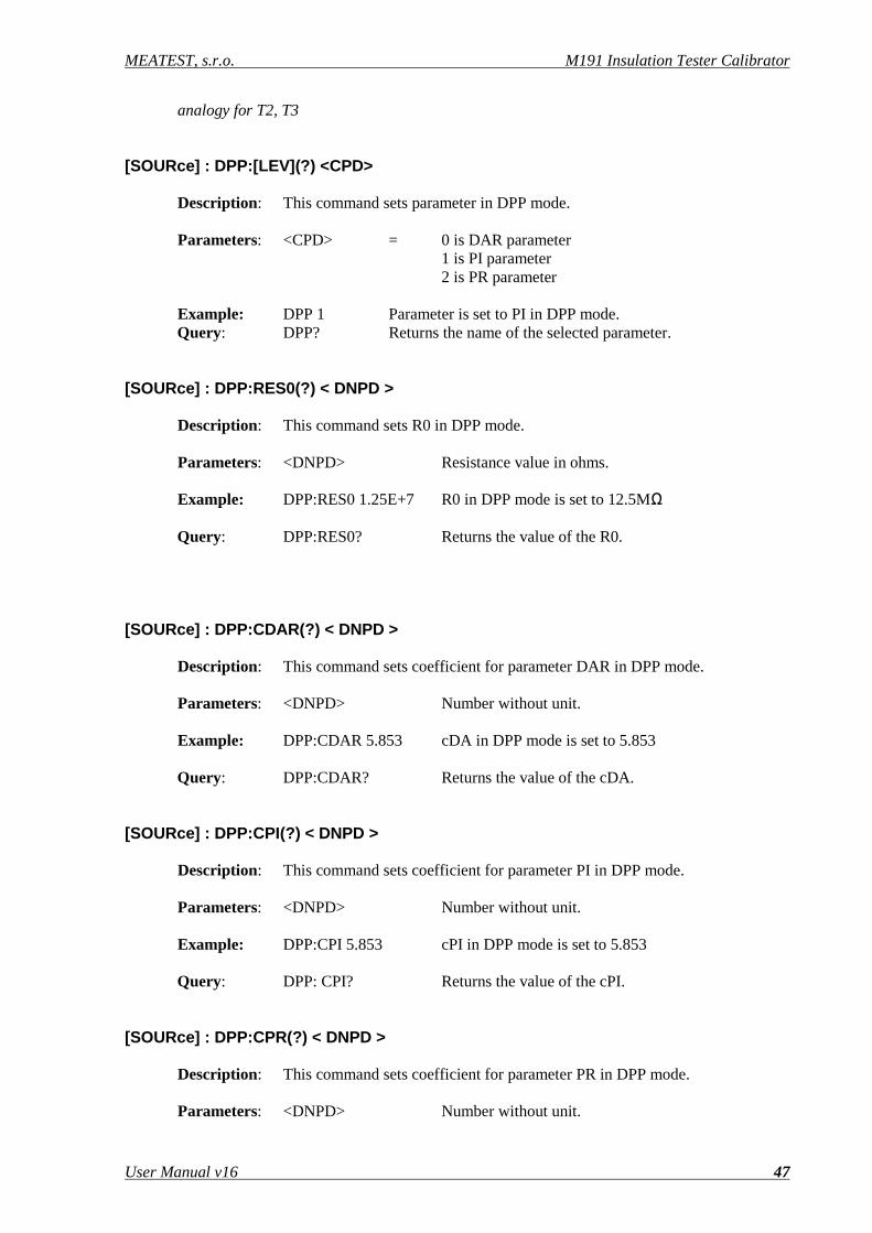
MEATEST, s.r.o. M191 Insulation Tester Calibrator
User Manual v16 47
analogy for T2, T3 [SOURce] : DPP:[LEV](?) <CPD> Description: This command sets parameter in DPP mode. Parameters: <CPD> = 0 is DAR parameter 1 is PI parameter 2 is PR parameter Example: DPP 1 Parameter is set to PI in DPP mode. Query: DPP? Returns the name of the selected parameter. [SOURce] : DPP:RES0(?) < DNPD > Description: This command sets R0 in DPP mode. Parameters: <DNPD> Resistance value in ohms. Example: DPP:RES0 1.25E+7 R0 in DPP mode is set to 12.5MΩ Query: DPP:RES0? Returns the value of the R0. [SOURce] : DPP:CDAR(?) < DNPD > Description: This command sets coefficient for parameter DAR in DPP mode. Parameters: <DNPD> Number without unit. Example: DPP:CDAR 5.853 cDA in DPP mode is set to 5.853 Query: DPP:CDAR? Returns the value of the cDA. [SOURce] : DPP:CPI(?) < DNPD > Description: This command sets coefficient for parameter PI in DPP mode. Parameters: <DNPD> Number without unit. Example: DPP:CPI 5.853 cPI in DPP mode is set to 5.853 Query: DPP: CPI? Returns the value of the cPI. [SOURce] : DPP:CPR(?) < DNPD > Description: This command sets coefficient for parameter PR in DPP mode. Parameters: <DNPD> Number without unit.
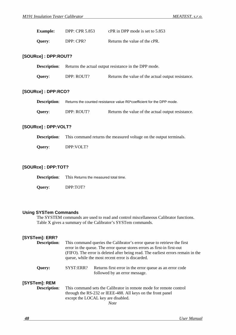
M191 Insulation Tester Calibrator MEATEST, s.r.o.
48 User Manual
Example: DPP: CPR 5.853 cPR in DPP mode is set to 5.853 Query: DPP: CPR? Returns the value of the cPR. [SOURce] : DPP:ROUT? Description: Returns the actual output resistance in the DPP mode. Query: DPP: ROUT? Returns the value of the actual output resistance. [SOURce] : DPP:RCO? Description: Returns the counted resistance value R0*coefficient for the DPP mode. Query: DPP: ROUT? Returns the value of the actual output resistance. [SOURce] : DPP:VOLT? Description: This command returns the measured voltage on the output terminals. Query: DPP:VOLT? [SOURce] : DPP:TOT? Description: This Returns the measured total time. Query: DPP:TOT? Using SYSTem Commands The SYSTEM commands are used to read and control miscellaneous Calibrator functions. Table X gives a summary of the Calibrator’s SYSTem commands. [SYSTem]: ERR? Description: This command queries the Calibrator’s error queue to retrieve the first error in the queue. The error queue stores errors as first-in first-out (FIFO). The error is deleted after being read. The earliest errors remain in the queue, while the most recent error is discarded. Query: SYST:ERR? Returns first error in the error queue as an error code followed by an error message. [SYSTem]: REM Description: This command sets the Calibrator in remote mode for remote control through the RS-232 or IEEE-488. All keys on the front panel except the LOCAL key are disabled.
Note
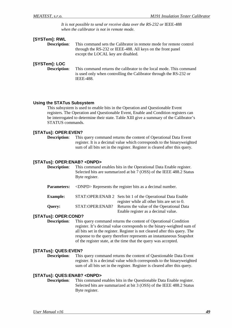
MEATEST, s.r.o. M191 Insulation Tester Calibrator
User Manual v16 49
It is not possible to send or receive data over the RS-232 or IEEE-488 when the calibrator is not in remote mode. [SYSTem]: RWL Description: This command sets the Calibrator in remote mode for remote control through the RS-232 or IEEE-488. All keys on the front panel except the LOCAL key are disabled. [SYSTem]: LOC Description: This command returns the calibrator to the local mode. This command is used only when controlling the Calibrator through the RS-232 or IEEE-488. Using the STATus Subsystem This subsystem is used to enable bits in the Operation and Questionable Event registers. The Operation and Questionable Event, Enable and Condition registers can be interrogated to determine their state. Table XIII give a summary of the Calibrator’s STATUS commands. [STATus]: OPER:EVEN? Description: This query command returns the content of Operational Data Event register. It is a decimal value which corresponds to the binaryweighted sum of all bits set in the register. Register is cleared after this query. [STATus]: OPER:ENAB? <DNPD> Description: This command enables bits in the Operational Data Enable register. Selected bits are summarized at bit 7 (OSS) of the IEEE 488.2 Status Byte register. Parameters: <DNPD> Represents the register bits as a decimal number. Example: STAT:OPER:ENAB 2 Sets bit 1 of the Operational Data Enable register while all other bits are set to 0. Query: STAT:OPER:ENAB? Returns the value of the Operational Data Enable register as a decimal value. [STATus]: OPER:COND? Description: This query command returns the content of Operational Condition register. It’s decimal value corresponds to the binary-weighted sum of all bits set in the register. Register is not cleared after this query. The response to the query therefore represents an instantaneous Snapshot of the register state, at the time that the query was accepted. [STATus]: QUES:EVEN? Description: This query command returns the content of Questionable Data Event register. It is a decimal value which corresponds to the binaryweighted sum of all bits set in the register. Register is cleared after this query. [STATus]: QUES:ENAB? <DNPD> Description: This command enables bits in the Questionable Data Enable register. Selected bits are summarized at bit 3 (OSS) of the IEEE 488.2 Status Byte register.

M191 Insulation Tester Calibrator MEATEST, s.r.o.
50 User Manual
Parameters: <DNPD> Represents the register bits as a decimal number. Example: STAT:QUES:ENAB 2 Sets bit 1 of the Questionable Data Enable register, while all other bits are set to 0. Query: SAF:QUES:ENAB? Returns the value of the Questionable Data Enable register as a decimal value. [STATus]: QUES:COND? Description: This query command returns the content of Questionable Condition register. It is a decimal value which corresponds to the binaryweighted sum of all bits set in the register. The register is not cleared after this query. The response to the query therefore represents an instantaneous Snapshot of the register state, at the time that the query was accepted. [STATus]: PRES Description: This query command clears all bits in the Operation Data Enable register and in the Questionable Data Enable register. Using IEEE 488.2 Common Commands The following commands are common to the IEEE 488.2 standard. A summary of the Calibrator’s IEEE Common Commands are listed in Table XIV. *IDN? Description: This query command returns the manufacturer’s name, model number, serial number, and firmware revision of the Calibrator. The reply is formatted as follows: MEATEST,M191,xxxxxx,1.00
Where xxxxxx is serial number. *OPC Description: This command sets the OPC bit in the ESR (Event Status Register) when all pending operations are complete. *OPC? Description: This command returns “1” to the output queue after all pending operations are complete. *WAI Description: This command prevents the Calibrator from executing any further commands or queries until all previous remote commands have been executed. *RST Description: This command resets the Calibrator to its initial state. *TST? Description: This command launches an internal self-test and returns the self-test results (“0” = pass or “1” = fail). *STB? Description: This query command returns a number representing the STB register contents. The STB register carries the MSS bit status. *SRE <value> Description: This command sets the Service Request Enable register. Since bit 6 is
MEATEST, s.r.o. M191 Insulation Tester Calibrator
User Manual v16 51
not used, the maximum value is 191. *SRE? Description: This query command returns the Service Request Enable number. *ESR? Description: This query command returns the contents of the Event Status Register and clears the register. *ESE <value> Description: This command programs the Event Status Enable register bits. Parameter value is a number in the range of 0 – 255. *ESE? Description: This query command returns the value in the Event Status Enable register. *CLS Description: This command clears the Event Status Register and the Status Byte Register with the exception of the MAV bit and output queue. The output line is not reset.

M191 Insulation Tester Calibrator MEATEST, s.r.o.
52 User Manual
9.4 Standard Status Data Structures All status registers are defined by the IEEE-488.2 standard. The programmer has access to Status Register, Enable Register and Output Queue in the Calibrator.
Fig 19 Data structure
Status data structure of M140 Calibrator contains following registers:
STB – Status Byte Register SRE – Service Request Enable Register ESR – Event Status Register ESE – Event Status Enable Register Output Queue
STB Status Byte Register
The summary messages from the Event Status Register and Output Queue are used to set or clear the appropriate bits (B4 and B5) of the Status Byte Register. These bits do not latch, and their states (0 or 1) are solely dependent on the summary messages (0 or 1). For example, if the Standard Event Register is read, its register
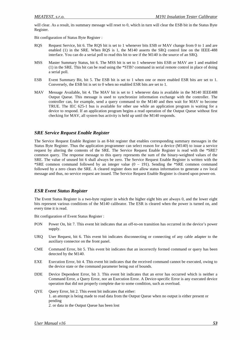
MEATEST, s.r.o. M191 Insulation Tester Calibrator
User Manual v16 53
will clear. As a result, its summary message will reset to 0, which in turn will clear the ESB bit in the Status Byte Register.
Bit configuration of Status Byte Register :
RQS Request Service, bit 6. The RQS bit is set to 1 whenever bits ESB or MAV change from 0 to 1 and are enabled (1) in the SRE. When RQS is 1, the M140 asserts the SRQ control line on the IEEE-488 interface. You can do a serial poll to read this bit to see if the M140 is the source of an SRQ.
MSS Master Summary Status, bit 6. The MSS bit is set to 1 whenever bits ESB or MAV are 1 and enabled (1) in the SRE. This bit can be read using the *STB? command in serial remote control in place of doing a serial poll.
ESB Event Summary Bit, bit 5. The ESB bit is set to 1 when one or more enabled ESR bits are set to 1. Conversely, the ESB bit is set to 0 when no enabled ESR bits are set to 1.
MAV Message Available, bit 4. The MAV bit is set to 1 whenever data is available in the M140 IEEE488 Output Queue. This message is used to synchronize information exchange with the controller. The controller can, for example, send a query command to the M140 and then wait for MAV to become TRUE. The IEC 625-1 bus is available for other use while an application program is waiting for a device to respond. If an application program begins a read operation of the Output Queue without first checking for MAV, all system bus activity is held up until the M140 responds.
SRE Service Request Enable Register
The Service Request Enable Register is an 8-bit register that enables corresponding summary messages in the Status Byte Register. Thus the application programmer can select reason for a device (M140) to issue a service request by altering the contents of the SRE. The Service Request Enable Register is read with the *SRE? common query. The response message to this query represents the sum of the binary-weighted values of the SRE. The value of unused bit 6 shall always be zero. The Service Request Enable Register is written with the *SRE common command followed by an integer value (0 – 191). Sending the *SRE common command followed by a zero clears the SRE. A cleared register does not allow status information to generate a rsv local message and thus, no service request are issued. The Service Request Enable Register is cleared upon power-on.
ESR Event Status Register
The Event Status Register is a two-byte register in which the higher eight bits are always 0, and the lower eight bits represent various conditions of the M140 calibrator. The ESR is cleared when the power is turned on, and every time it is read.
Bit configuration of Event Status Register :
PON Power On, bit 7. This event bit indicates that an off-to-on transition has occurred in the device’s power supply.
URQ User Request, bit 6. This event bit indicates disconnecting or connecting of any cable adapter to the auxiliary connector on the front panel.
CME Command Error, bit 5. This event bit indicates that an incorrectly formed command or query has been detected by the M140.
EXE Execution Error, bit 4. This event bit indicates that the received command cannot be executed, owing to the device state or the command parameter being out of bounds.
DDE Device Dependent Error, bit 3. This event bit indicates that an error has occurred which is neither a Command Error, a Query Error, nor an Execution Error. A Device-specific Error is any executed device operation that did not properly complete due to some condition, such as overload.
QYE Query Error, bit 2. This event bit indicates that either: 1. an attempt is being made to read data from the Output Queue when no output is either present or pending 2. or data in the Output Queue has been lost
M191 Insulation Tester Calibrator MEATEST, s.r.o.
54 User Manual
OPC Operation Complete, bit 0. This event bit is generated in response to the *OPC command. It indicates that the device has completed all selected pending operations.
ESE Event Status Enable Register
The Event Status Enable Register allows one or more events in the Event Status Register to be reflected in the ESB summary-message bit. This register is defined for 8 bits, each corresponding to the bits in the Event Status Register. The Event Status Enable Register is read with the common query *ESE?. Data is returned as a binary-weighted value. The Event Status Enable Register is written to by the common command, *ESE. Sending the *ESE common command followed by a zero clears the ESE. The Event Status Enable Register is cleared upon power-on.
Output Queue
The Output Queue stores response messages until they are read. The availability of output is summarized by the MAV (message available) summary message. The MAV summary message is used to synchronize information exchange with the controller. The Output Queue shall be a first in, first out (FIFO) Queue. The Output Queue is cleared upon power-on.
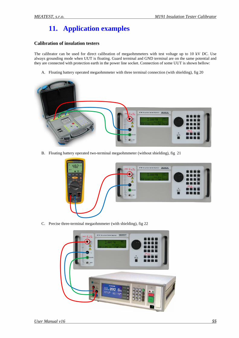
MEATEST, s.r.o. M191 Insulation Tester Calibrator
User Manual v16 55
11. Application examples Calibration of insulation testers The calibrator can be used for direct calibration of megaohmmeters with test voltage up to 10 kV DC. Use always grounding mode when UUT is floating. Guard terminal and GND terminal are on the same potential and they are connected with protection earth in the power line socket. Connection of some UUT is shown bellow:
A. Floating battery operated megaohmmeter with three terminal connection (with shielding), fig 20
B. Floating battery operated two-terminal megaohmmeter (without shielding), fig 21
C. Precise three-terminal megaohmmeter (with shielding), fig 22
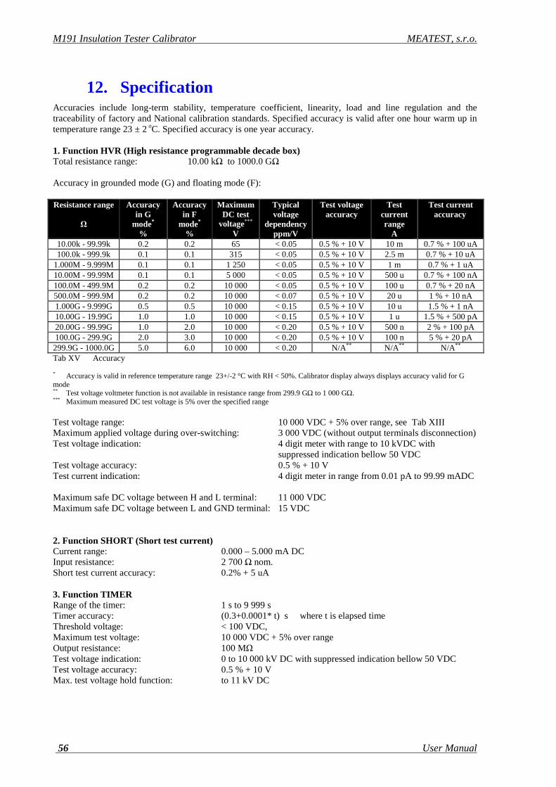
M191 Insulation Tester Calibrator MEATEST, s.r.o.
56 User Manual
12. Specification Accuracies include long-term stability, temperature coefficient, linearity, load and line regulation and the traceability of factory and National calibration standards. Specified accuracy is valid after one hour warm up in temperature range 23 ± 2 oC. Specified accuracy is one year accuracy. 1. Function HVR (High resistance programmable decade box) Total resistance range: 10.00 kΩ to 1000.0 GΩ Accuracy in grounded mode (G) and floating mode (F): Resistance range
Ω
Accuracy in G
mode* %
Accuracy in F
mode* %
Maximum DC test
voltage*** V
Typical voltage
dependency ppm/V
Test voltage accuracy
Test current range
A
Test current accuracy
10.00k - 99.99k 0.2 0.2 65 < 0.05 0.5 % + 10 V 10 m 0.7 % + 100 uA 100.0k - 999.9k 0.1 0.1 315 < 0.05 0.5 % + 10 V 2.5 m 0.7 % + 10 uA
1.000M - 9.999M 0.1 0.1 1 250 < 0.05 0.5 % + 10 V 1 m 0.7 % + 1 uA 10.00M - 99.99M 0.1 0.1 5 000 < 0.05 0.5 % + 10 V 500 u 0.7 % + 100 nA 100.0M - 499.9M 0.2 0.2 10 000 < 0.05 0.5 % + 10 V 100 u 0.7 % + 20 nA 500.0M - 999.9M 0.2 0.2 10 000 < 0.07 0.5 % + 10 V 20 u 1 % + 10 nA 1.000G - 9.999G 0.5 0.5 10 000 < 0.15 0.5 % + 10 V 10 u 1.5 % + 1 nA 10.00G - 19.99G 1.0 1.0 10 000 < 0.15 0.5 % + 10 V 1 u 1.5 % + 500 pA 20.00G - 99.99G 1.0 2.0 10 000 < 0.20 0.5 % + 10 V 500 n 2 % + 100 pA 100.0G - 299.9G 2.0 3.0 10 000 < 0.20 0.5 % + 10 V 100 n 5 % + 20 pA 299.9G - 1000.0G 5.0 6.0 10 000 < 0.20 N/A** N/A** N/A** Tab XV Accuracy * Accuracy is valid in reference temperature range 23+/-2 °C with RH < 50%. Calibrator display always displays accuracy valid for G mode ** Test voltage voltmeter function is not available in resistance range from 299.9 GΩ to 1 000 GΩ. *** Maximum measured DC test voltage is 5% over the specified range Test voltage range: 10 000 VDC + 5% over range, see Tab XIII Maximum applied voltage during over-switching: 3 000 VDC (without output terminals disconnection) Test voltage indication: 4 digit meter with range to 10 kVDC with
suppressed indication bellow 50 VDC Test voltage accuracy: 0.5 % + 10 V Test current indication: 4 digit meter in range from 0.01 pA to 99.99 mADC Maximum safe DC voltage between H and L terminal: 11 000 VDC Maximum safe DC voltage between L and GND terminal: 15 VDC 2. Function SHORT (Short test current) Current range: 0.000 – 5.000 mA DC Input resistance: 2 700 Ω nom. Short test current accuracy: 0.2% + 5 uA 3. Function TIMER Range of the timer: 1 s to 9 999 s Timer accuracy: (0.3+0.0001* t) s where t is elapsed time Threshold voltage: < 100 VDC, Maximum test voltage: 10 000 VDC + 5% over range Output resistance: 100 MΩ Test voltage indication: 0 to 10 000 kV DC with suppressed indication bellow 50 VDC Test voltage accuracy: 0.5 % + 10 V Max. test voltage hold function: to 11 kV DC
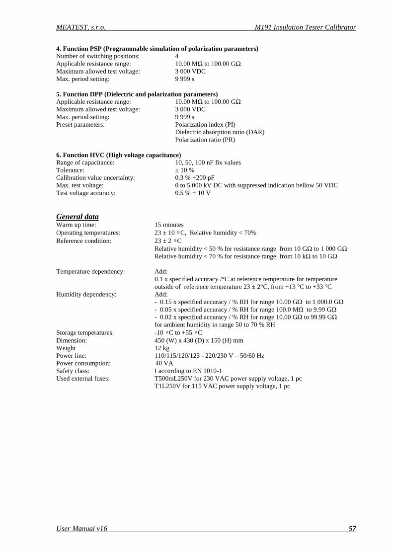
MEATEST, s.r.o. M191 Insulation Tester Calibrator
User Manual v16 57
4. Function PSP (Programmable simulation of polarization parameters) Number of switching positions: 4 Applicable resistance range: 10.00 MΩ to 100.00 GΩ Maximum allowed test voltage: 3 000 VDC Max. period setting: 9 999 s 5. Function DPP (Dielectric and polarization parameters) Applicable resistance range: 10.00 MΩ to 100.00 GΩ Maximum allowed test voltage: 3 000 VDC Max. period setting: 9 999 s Preset parameters: Polarization index (PI)
Dielectric absorption ratio (DAR) Polarization ratio (PR)
6. Function HVC (High voltage capacitance) Range of capacitance: 10, 50, 100 nF fix values Tolerance: ± 10 % Calibration value uncertainty: 0.3 % +200 pF Max. test voltage: 0 to 5 000 kV DC with suppressed indication bellow 50 VDC Test voltage accuracy: 0.5 % + 10 V General data Warm up time: 15 minutes Operating temperatures: 23 ± 10 º C, Relative humidity < 70% Reference condition: 23 ± 2 º C Relative humidity < 50 % for resistance range from 10 GΩ to 1 000 GΩ Relative humidity < 70 % for resistance range from 10 kΩ to 10 GΩ Temperature dependency: Add: 0.1 x specified accuracy /°C at reference temperature for temperature
outside of reference temperature 23 ± 2°C, from +13 °C to +33 °C Humidity dependency: Add: - 0.15 x specified accuracy / % RH for range 10.00 GΩ to 1 000.0 GΩ - 0.05 x specified accuracy / % RH for range 100.0 MΩ to 9.99 GΩ - 0.02 x specified accuracy / % RH for range 10.00 GΩ to 99.99 GΩ for ambient humidity in range 50 to 70 % RH Storage temperatures: -10 º C to +55 º C Dimension: 450 (W) x 430 (D) x 150 (H) mm Weight 12 kg Power line: 110/115/120/125 - 220/230 V – 50/60 Hz Power consumption: 40 VA Safety class: I according to EN 1010-1 Used external fuses: T500mL250V for 230 VAC power supply voltage, 1 pc T1L250V for 115 VAC power supply voltage, 1 pc
M191 Insulation Tester Calibrator MEATEST, s.r.o.
58 User Manual
13. Accessory Basic accessories (included in delivery) • Power line cord 1 pc • User´s manual 1 pc • Test report 1 pc • Spare fuse 1 pc • Opt 191-10 Test cable 1000V/20A black 1 pc • Opt 191-11 Test cable 5000V/20A red 1 pc • Opt 191-12 Green/yellow grounding lead banana-banana 1 pc • Cable RS-232 1 pc
Options (extra ordered) • Opt 191-10 Test cable 1000V/20A black • Opt 191-11 Test cable 5000V/20A red • Opt 191-12 Green/yellow grounding lead banana-banana • Cable GPIB IEEE488/IEEE488, 2m Manufacturer MEATEST, s.r.o tel: +420 – 543 250 886 Zelezna 3, 619 00 Brno fax: +420 – 543 250 890 Czech Republic [email protected] Service MEATEST, s.r.o tel: +420 – 543 250 886 Zelezna 3, 619 00 Brno fax: +420 – 543 250 890 Czech Republic [email protected] Local distributors


