19
PLC Fundamentals Module 2: Hardware and Terminology PREPARED BY Academic Services Unit January 2013 © Applied Technology High Schools, 2013
| Date post: | 05-Oct-2018 |
| Category: |
Documents |
| Upload: | hoangthien |
| View: | 213 times |
| Download: | 0 times |
PLC Fundamentals Module 2:
Hardware and Terminology
PREPARED BY
Academic Services Unit
January 2013
© Applied Technology High Schools, 2013

ATE 326 – PLC Fundamentals
Module 2: Hardware and Terminology 2
Module 2: Hardware and Terminology
Module Objectives Upon successful completion of this module, students should be able to:
1. Name the PLC hardware parts.
2. Differentiate between analog and digital inputs, and give examples for each.
3. List the inputs and outputs for a given application, and categorize them as analog and digital.
4. Name the LOGO! Basic module parts.
5. Connect input and output devices and program the LOGO! to perform simple tasks.
Module Contents: Topic Page No.
2.1 PLC Hardware 3
2.2 LOGO! Hardware 8
2.3 LOGO! Wiring 9
2.4 Lab Activity 1 12
2.5 Lab Activity 2 14
2.6 Review Exercise 17
ATE 326–PLC Fundamentals
Module 2: Hardware and Terminology 3
2.1 PLC Hardware
Before writing PLC programs you should be familiar with the PLC
hardware. You should be in a position to identify what can be an input
and what can be an output for a PLC, and where exactly you connect the
different inputs and outputs. As you studied in the first module, the
Programmable Logic Controller is a device that can be programmed to
perform control functions. Since it is a digital device, it stores information
in the form of ON/OFF conditions referred to as binary digits or bits. Even
though the PLC uses both digital and analog signals, the CPU can
understand only digital signals.
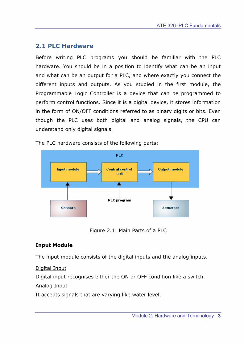
The PLC hardware consists of the following parts:
Figure 2.1: Main Parts of a PLC
Input Module
The input module consists of the digital inputs and the analog inputs.
Digital Input
Digital input recognises either the ON or OFF condition like a switch.
Analog Input
It accepts signals that are varying like water level.

ATE 326 – PLC Fundamentals
Module 2: Hardware and Terminology 4
Observe figure 2.2. It shows the relation between the logic level and the
switch condition. Logic 1 indicates that a signal is present and the
switch is ON. Logic 0 indicates that the signal is absent or the switch
is OFF. Is the switch a digital input or an analog input? What do you
think?
Figure 2.2: Normally Open Pushbutton
A normally open (NO) pushbutton is used in the above example. When
the switch is not pressed, no voltage is present at the PLC Input 1 and
sets it to OFF state. When the switch is pressed, 24V DC is applied to the
PLC input and sets it to ON state. A normally closed (NC) pushbutton acts
opposite to the normally open (NO) pushbutton. Figure 2.3 shows the
pushbutton symbols.
Figure 2.3: Pushbutton Symbols
ATE 326–PLC Fundamentals
Module 2: Hardware and Terminology 5
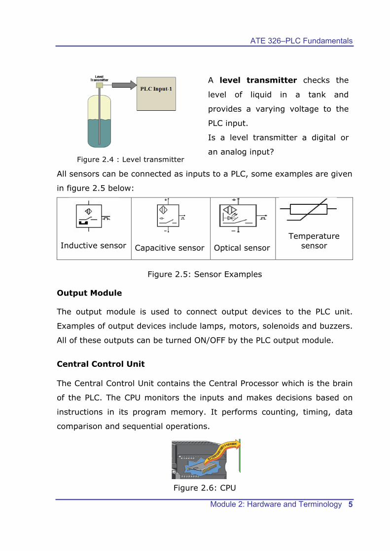
Figure 2.4 : Level transmitter
A level transmitter checks the
level of liquid in a tank and
provides a varying voltage to the
PLC input.
Is a level transmitter a digital or
an analog input?
All sensors can be connected as inputs to a PLC, some examples are given
in figure 2.5 below:
Inductive sensor
Capacitive sensor
Optical sensor
Temperature sensor
Figure 2.5: Sensor Examples
Output Module
The output module is used to connect output devices to the PLC unit.
Examples of output devices include lamps, motors, solenoids and buzzers.
All of these outputs can be turned ON/OFF by the PLC output module.
Central Control Unit The Central Control Unit contains the Central Processor which is the brain
of the PLC. The CPU monitors the inputs and makes decisions based on
instructions in its program memory. It performs counting, timing, data
comparison and sequential operations.
Figure 2.6: CPU

ATE 326 – PLC Fundamentals
Module 2: Hardware and Terminology 6
Exercise Review the application given below, and list all the inputs and outputs and
classify the inputs as analog or digital.
A controller is needed for a hydraulic press (see Figure 2.7). The press
uses a 24VDC double actuated solenoid valve to advance and retract the
press. This device has three wires: one for common, one to advance and
one to retract. A large hydraulic pump should be running as long as the
press is ON. Three push buttons are used, one is a NC stop button, the
other is a NO manual retract button, and the third is a NO start automatic
cycle button. Two limit switches at the top and bottom of the press must
also be used.
Figure 2.7: Press machine control unit
Input Output Analog/Digital
ATE 326–PLC Fundamentals
Module 2: Hardware and Terminology 7
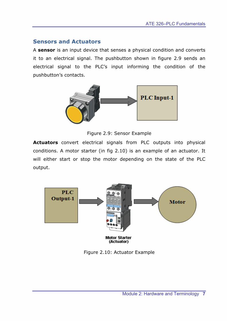
Sensors and Actuators A sensor is an input device that senses a physical condition and converts
it to an electrical signal. The pushbutton shown in figure 2.9 sends an
electrical signal to the PLC’s input informing the condition of the
pushbutton’s contacts.
Figure 2.9: Sensor Example
Actuators convert electrical signals from PLC outputs into physical
conditions. A motor starter (in fig 2.10) is an example of an actuator. It
will either start or stop the motor depending on the state of the PLC
output.
Figure 2.10: Actuator Example
ATE 326 – PLC Fundamentals
Module 2: Hardware and Terminology 8
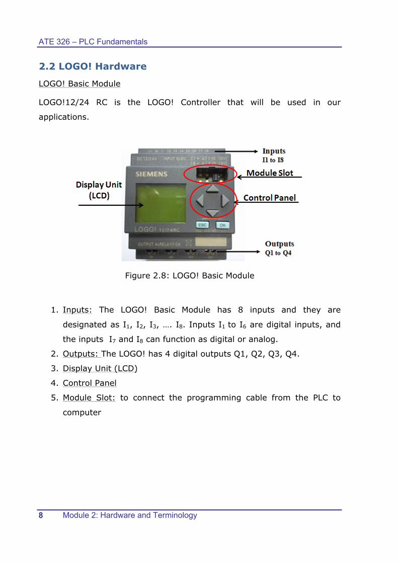
2.2 LOGO! Hardware
LOGO! Basic Module
LOGO!12/24 RC is the LOGO! Controller that will be used in our
applications.
Figure 2.8: LOGO! Basic Module
1. Inputs: The LOGO! Basic Module has 8 inputs and they are
designated as I1, I2, I3, …. I8. Inputs I1 to I6 are digital inputs, and
the inputs I7 and I8 can function as digital or analog.
2. Outputs: The LOGO! has 4 digital outputs Q1, Q2, Q3, Q4.
3. Display Unit (LCD)
4. Control Panel
5. Module Slot: to connect the programming cable from the PLC to
computer

ATE 326–PLC Fundamentals
Module 2: Hardware and Terminology 9
2.3 LOGO! Wiring
2.3.1: Connecting the power supply
PLC devices need an electrical power supply that can be either an AC, or
DC supply. In the previous module lab activity, you have seen that
LOGO! 12/24RC needs a DC supply, and you had connected the power
supply to the LOGO! as shown in figure 2.11.
Figure 2.11: Connecting LOGO! to power supply
2.3.2: Connecting LOGO! Inputs
Figure 2.12 shows the hardware/wiring details of connecting the inputs to
the LOGO! You are already familiar with connecting the inputs to the
LOGO! In figure 2.12, switch S1 is connected to I1 and switch S2 is
connected to I2.
Figure 2.12: Connecting inputs

ATE 326 – PLC Fundamentals
Module 2: Hardware and Terminology 10
2.3.3: Connecting Sensors to the LOGO!
For two wire sensors, the connection can be done easily by taking one
wire to the positive terminal of the power supply and the second wire to
the LOGO! input ( See figure 2.13)
Figure 2.13: Connecting a 2-wire sensor
For three-wire sensors, the sensor type must be taken into consideration
while programming. A PNP sensor can be considered as a normally open
pushbutton and an NPN sensor can be considered as a normally closed
pushbutton.
Figure 2.14: Connecting a 3-wire sensor

ATE 326–PLC Fundamentals
Module 2: Hardware and Terminology 11
2.3.4: Connecting LOGO! Outputs.
LOGO! …R… version is equipped with relay outputs. The potential of the
relay contacts is isolated from the power supply and the inputs. As shown
in fig 2.23, various loads can be connected to the relay outputs, for
example, lamps, motors, relays etc.
Figure 2.15: Connecting loads to outputs
ATE 326 – PLC Fundamentals
Module 2: Hardware and Terminology 12
2.4 Lab Activity 1 Objective: To identify the difference between normally open (NO) and normally closed (NC) pushbuttons. Material:
• 24 V power supply • NO pushbutton • NC pushbutton • PLC LOGO! Unit • Wires • Lamp
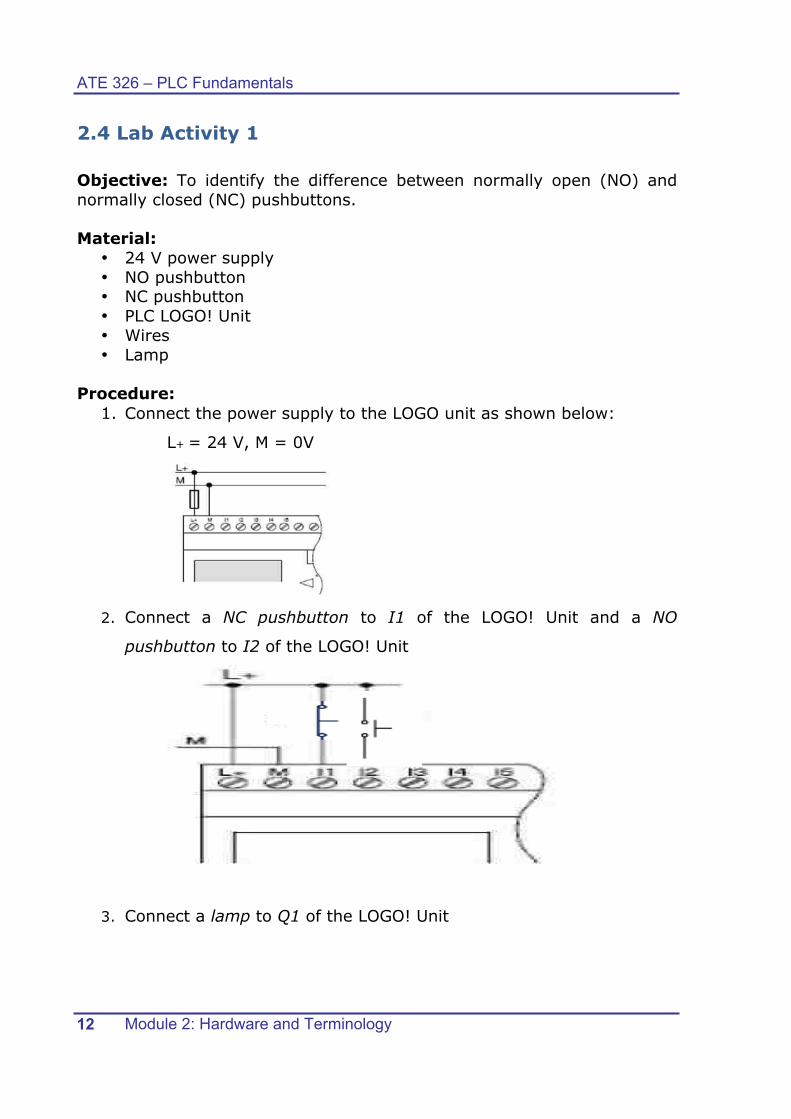
Procedure:
1. Connect the power supply to the LOGO unit as shown below:
L+ = 24 V, M = 0V
2. Connect a NC pushbutton to I1 of the LOGO! Unit and a NO
pushbutton to I2 of the LOGO! Unit
3. Connect a lamp to Q1 of the LOGO! Unit

ATE 326–PLC Fundamentals
Module 2: Hardware and Terminology 13
4. Switch on the power supply
5. Enter the following program in the LOGO! Unit using the on-board
keys.
6. Press ESC to return to the main screen and press start to run the
program.
7. Press NC pushbutton and observe the result. What do you observe?
_________________________________________________
8. Stop and clear the program. Repeat step 4 by changing I1 to I2.
Then, run the new program.
9. Press NO pushbutton and observe the result. What do you observe?
_________________________________________________
Question:
§ Fill the following table:
PLC
input
Pushbutton type
(NO/NC)
Lamp condition
when pressed
(ON/OFF)
Lamp condition
when released
(ON/OFF)
I1
I2

ATE 326 – PLC Fundamentals
Module 2: Hardware and Terminology 14
2.5 Lab Activity 2 Objective: To test the function of the optical sensor and inductive sensor connected to the LOGO! Unit. Material:
• 24 V power supply • Inductive sensor • Optical sensor • PLC LOGO! Unit • Wires • Motor
Procedure:
1. Connecting the power supply
Connect the power supply to the LOGO unit as shown below:
L+ = 24 V, M = 0V
2. Connecting the inputs
Connect the optical sensor to the LOGO! Unit as follow:
v Brown wire à 24V
v Blue wire à 0V
v Black wire à I3
Connect the inductive sensor to the LOGO! Unit as follow:
v Brown wire à 24V
v Blue wire à 0V
v Black wire à I4
v White wire à unconnected
ATE 326–PLC Fundamentals
Module 2: Hardware and Terminology 15
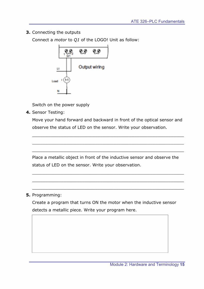
3. Connecting the outputs
Connect a motor to Q1 of the LOGO! Unit as follow:
Switch on the power supply
4. Sensor Testing:
Move your hand forward and backward in front of the optical sensor and
observe the status of LED on the sensor. Write your observation.
__________________________________________________________
__________________________________________________________
__________________________________________________________
Place a metallic object in front of the inductive sensor and observe the
status of LED on the sensor. Write your observation.
__________________________________________________________
__________________________________________________________
__________________________________________________________
5. Programming:
Create a program that turns ON the motor when the inductive sensor
detects a metallic piece. Write your program here.

ATE 326 – PLC Fundamentals
Module 2: Hardware and Terminology 16
Run your program.
Place a metallic piece in front of the inductive sensor to confirm that the
motor operates.
Clear your previous program.
Create a new program that turns ON the motor when the optical
sensor detects an object in front of it. Write your program here.
Run your program.
Place an object in front of the inductive sensor to confirm that the motor
operates.
ATE 326–PLC Fundamentals
Module 2: Hardware and Terminology 17
2.6 Review Exercise
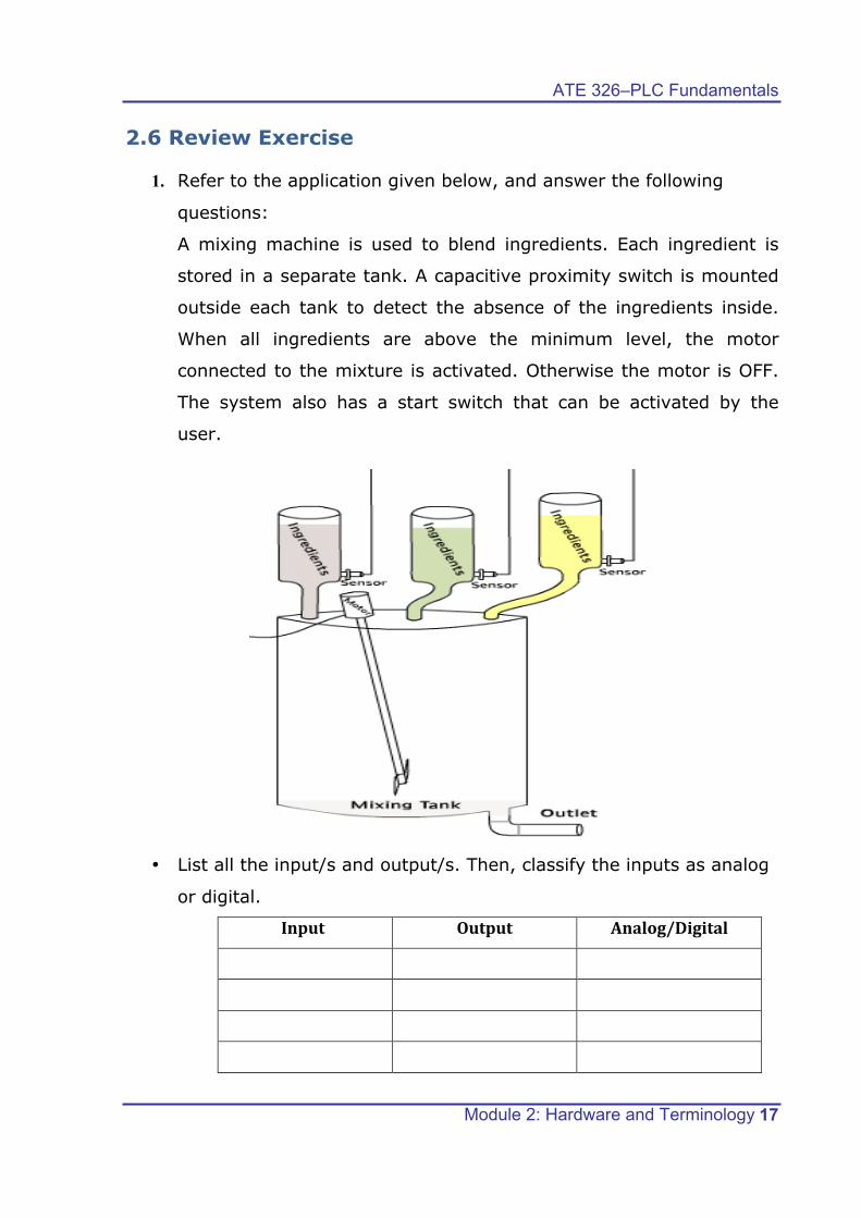
1. Refer to the application given below, and answer the following
questions:
A mixing machine is used to blend ingredients. Each ingredient is
stored in a separate tank. A capacitive proximity switch is mounted
outside each tank to detect the absence of the ingredients inside.
When all ingredients are above the minimum level, the motor
connected to the mixture is activated. Otherwise the motor is OFF.
The system also has a start switch that can be activated by the
user.
• List all the input/s and output/s. Then, classify the inputs as analog
or digital.
Input Output Analog/Digital

ATE 326 – PLC Fundamentals
Module 2: Hardware and Terminology 18
• Draw all the inputs and outputs and connect them to the LOGO! PLC
given below.

ATE 326–PLC Fundamentals
Module 2: Hardware and Terminology 19
2. A normally open pushbutton is used to turn ON an automatic filling
system. When the normally closed liquid level detector is activated,
a pump starts filling the tank. Once the tank is full a normally open
liquid level detector sends a signal to the PLC and the PLC turns the
pump OFF.
Complete the wiring diagram below.


