56
CEMENT TEST EQUIPMENT, INC. Tulsa, Oklahoma, USA M2000, M2000-HT & Dual M2000 Ultrasonic Cement Analyzer Instruction Manual

CEMENT TEST EQUIPMENT, INC. Tulsa, Oklahoma, USA
M2000, M2000-HT & Dual M2000
Ultrasonic Cement Analyzer
Instruction Manual

Cement Test Equipment, Inc. 5704 E. Admiral Blvd.
Tulsa, OK 74115 Phone 918.835.4454 � Fax 918.835.4475
Rev. H 03-11-2015
i
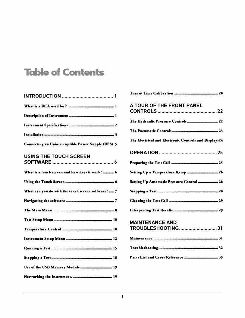
Table of Contents
INTRODUCTION ...................................... 1
What is a UCA used for? .............................................. 1
Description of Instrument ............................................. 1
Instrument Specifications ............................................. 2
Installation ..................................................................... 3
Connecting an Uninterruptible Power Supply (UPS) 5
USING THE TOUCH SCREEN SOFTWARE ............................................. 6
What is a touch screen and how does it work? ........... 6
Using the Touch Screen ................................................. 6
What can you do with the touch screen software? ..... 7
Navigating the software ................................................ 7
The Main Menu ............................................................. 8
Test Setup Menu .......................................................... 10
Temperature Control .................................................. 10
Instrument Setup Menu .............................................. 12
Running a Test ............................................................. 15
Stopping a Test ............................................................ 18
Use of the USB Memory Module ................................ 19
Networking the Instrument. ....................................... 19
Transit Time Calibration ............................................ 20
A TOUR OF THE FRONT PANEL CONTROLS ............................................ 22
The Hydraulic Pressure Controls ............................... 22
The Pneumatic Controls .............................................. 23
The Electrical and Electronic Controls and Displays24
OPERATION ........................................... 25
Preparing the Test Cell ............................................... 25
Setting Up a Temperature Ramp ............................... 26
Setting Up Automatic Pressure Control .................... 26
Stopping a Test............................................................. 28
Cleaning the Test Cell ................................................. 29
Interpreting Test Results............................................. 29
MAINTENANCE AND TROUBLESHOOTING ............................ 31
Maintenance ................................................................. 31
Troubleshooting ........................................................... 32
Parts List and Cross Reference .................................. 35
i
I N T R O D U C T I O N
Introduction This chapter contains general information about the UCA and its uses as well as detailed specifications for the instrument and installation instructions.
What is a UCA used for?
ements are a critical element in the drilling, completion, workover, and abandonment of wells. For each application, a cement slurry is designed with specific properties and is given additives that provide predictable slurry density, volume, viscosity, compressive strength, fluid loss, gas migration,
and thickening time. The Model 2000 Ultrasonic Cement Analyzer (UCA) is used to provide a history of the strength development of a cement slurry as it cures under elevated temperature and pressure.
Description of Instrument The Ultrasonic Cement Analyzer (UCA) transmits an ultrasonic pulse through a cement slurry and measures the travel time of the pulse through the slurry. The travel time of the pulse through the slurry gives an indication of the compressive strength of the slurry. The compressive strength, along with temperature and pressure, are monitored as a function of time for the purpose of providing a strength history of a setting cement slurry.
The major features of the UCA are listed below:
• Easy to install and use.
• Direct replacement for Halliburton or Chandler UCA systems.
• Completely self contained. No need for pressure controllers, control boxes, or PC’s.
Chapter
1
I C O N K E Y
Important information
Potential Danger or
Safety Hazard
! Operational Warning
C
Our temperature controller and data acquisition system are so easy to operate you won’t even need a manual. We’ve thrown one in anyway, just in case.
1
I N T R O D U C T I O N
• All software is Windows based.
• Data may be plotted on a standard ink jet printer, stored on a USB flash memory stick, or archived to an external PC via an Ethernet connection.
• Tests are stored as .tdms files and may be retrieved and viewed by Cementlab or the Cementlab remote viewer software. Text files (.txt) may also be exported for interfacing with most word processors, text editors, spreadsheets, and database programs.
• Has built in, easy to use, touch screen control panel for control of data acquisition and temperature control. No more clunky temperature controllers to program. Temperature profile is displayed graphically before test starts to reduce mistakes.
• Available with integral pump and relief valve for soak pressure control. Does not require separate pressure controller.
• May be used with Halliburton Pressure Controller as an option.
• Unit may be operated with an optional uninterruptible power supply (UPS) that will keep all functions (except heater) of the UCA operating for up to one hour during power outages.
A cross-reference list of Chandler and Halliburton part numbers and equivalent CTE part numbers is provided in Chapter 5, Maintenance and Servicing.
Instrument Specifications The specifications below apply to the CTE, Inc. Model 2000 UCA.
ELECTRICAL Input Voltage: 230 VAC (+15%) Input Power: 2500W Input Current: 11 A Input Frequency: 50-60 Hz
MECHANICALHeight: 14.5 in. (36.8 cm) Width: 26 in. (66 cm) Depth: 15.3 in. (38.9 cm) Weight: 110 lb. (50 kg)
2
I N T R O D U C T I O N
ENVIRONMENTALOperating Temperature: (32 to 120°F) 0-50°C Operating Humidity: 0-95% non-condensing
HEATERHeater Power: 2,000 W Heater Type: Cast heater with cooling coils Heater Control: Solid state relay
UTILITIES - WATER AND AIRCompressed Air: 100 psig (6.8 bar) Cooling Water Pressure: 100 psig (6.8 bar) maximum Utility Inlets: ¼ inch female NPT
Installation Upon uncrating the instrument, verify that the instrument and any spare parts on the packing have been received and are undamaged. Notify CTE if anything is missing or damaged.
Once the instrument has been moved to its desired location, air, water, and electrical connections can be made. The air inlet, water inlet, and water drain connections are each ¼ inch female NPT connections and are located on the lower right rear of the instrument. A number of ¼ inch male NPT to 8mm tube fittings are included for international locations.
Connect the coolant and pressurizing water to the connectors labeled COOLING WATER and WATER INLET, respectively, on the rear panel of the instrument. Each fitting has a ¼ inch female N.P.T. connection. The water must be clean and free of debris that could cause failure of the pump or relief valve. A water filter (C-0739) is included and must be installed on the water inlet to promote trouble free pump and relief valve operation. Depending on the quality of the water supply, the filter may need to be replaced more frequently. Follow the water filter manufacturer’s recommended replacement interval. Neglecting to install the water inlet filter will void the instrument warranty. Water inlet supply water must be filtered at 5 micron or better and have a viscosity between 1–100 cst. Pump performance is affected by many operating conditions. Extreme temperatures, pressures, and high duty cycles will increase maintenance frequency. All units are lubricated at the factory with silicone free semi-synthetic grease. After 2-3 months of normal (50% duty) operation, the standard spool seals should be inspected for wear and relubricated. Based on this inspection, future maintenance intervals can be
It is a good idea to leave room behind the instrument so that qualified personnel may have service access. If this is not possible, try to make the unit easy to disconnect and move for service.
3
I N T R O D U C T I O N
planned and further disassembly and lubrication of other moving seals may be necessary.
Connect drain lines to the connectors labeled WATER DRAIN and COOLING DRAIN on the rear panel of the instrument. The fittings have ¼ inch female N.P.T. connections. The drain system must be capable of handling hot water up to 212 °F (100°C) and brief surges of up to 500°F (260°C) steam for short periods of time during initial cooling of the instrument. If two or more UCA’s are connected to a common drain line, it is recommended that the drain be 3/8 inch (10mm) inside diameter, minimum. It is also recommended that the drain system be all metal.
Connect the air supply to the connector labeled AIR INLET on the rear panel of the instrument. The fitting has a ¼ inch female N.P.T. connection. The air should be dry and relatively free from dirt and oil. The air should be supplied at a pressure of 20-100 psig (1.4-6.8 bar). Compressed nitrogen may also be used in place of the compressed air if necessary. Drive air should be filtered between 5μ and 40μ and have a maximum dewpoint of 50°F. Very wet air will wash out lubricant and cause exhaust icing. Very dry air (dew point below 0°F) will dry out lubricant and cause premature failure of spool o-rings.
• If high pressure bottles of nitrogen or air are used to operate the instrument, make certain that the pressure supplied to the instrument does not exceed 100 psig (6.8 bar). Applying high pressure gas to the instrument can cause tube rupture and possible injury.
Electrical connections are made using the receptacle on the rear of the instrument. A power cord (part number C-0156) is supplied with the instrument. Please observe the following precautions when making the wiring connections.
• Wiring should be done by a qualified installer in accordance with local electrical codes.
4
I N T R O D U C T I O N
• The instrument should be securely connected to a separate earth ground. The ground wire must be larger in diameter than the supply conductors
• An 8BC or larger fire extinguisher to fight electrical and oil fires should be placed within 50 feet of the consistometer.
Some components such as the touch screen LCD monitor may be removed from the instrument prior to shipment and shipped in a separate container to prevent damage. This device must be reinstalled before operating the instrument. The monitor cables include one USB and one VGA cable which must be connected to the control box and one AC power cable which must be connected to the 230 VAC input on the monitor.
If a printer is included with the instrument, it may be connected to the control box. Connect the USB connector on the printer cable to the control box. The printer must also be connected to a suitable power source. Refer to the printer documentation for power requirements.
Connecting an Uninterruptible Power Supply (UPS)Applicable only if there are two receptacles on the rear of the unit labeled UPSthat may be used to connect an uninterruptible power supply (UPS). In the event of a power failure, the UPS will operate all functions of the UCA, except the heater, for up to one hour to prevent loss of test. To connect the UPS, select the power cord supplied with the UPS and connect one end to the UPS input and the other end to the UCA. The cord will fit only one receptacle. Locate the other power cord supplied with the instrument (part number C-0275) and connect one end to the output of the UPS and the other end to the other UPSreceptacle on the rear of the UCA. Press the ON button on the UPS. A green light will appear on the UPS when it is operating properly. If the unit beeps and a red light comes on, a power failure has occurred and the unit is being powered by the UPS. Note that if the POWER switch is turned OFF and the UPS is not turned OFF, the instrument will not power down.
Before attempting to operate the instrument, it is recommended that the operators read the remainder of the manual and study the drawings that appear in the Drawings/Schematics section of this manual to become familiar with the UCA operation.
Before plugging the monitor into the rear of the UCA, make certain power to the instrument is off.
If a UPS is not used, the C-0275 cord must be installed between the two rear panel receptacles or the instrument will not operate.
5

A T O U R O F T H E F R O N T P A N E L C O N T R O L S
Using the Touch Screen Software This chapter contains specific information on how to use the touch screen software plus instructions on how to network the UCA and connect and use the USB Memory Module.
What is a touch screen and how does it work? Touch screens were created to provide operators with an easy to use interface. They allow the user to input and view data without a keyboard or mouse. The touch surface is able to detect contact and send position information back to the processor. Using the touch screen has the same result of using a mouse to point and click. One mouse click is accomplished by one touch of the screen. A double-click is achieved with two quick touches. With this standard method of input, no special software is required to utilize the screen.
Using the Touch Screen Most any object may be used on the touch-screens. Experimentation will quickly show which objects will activate the screen and which will not. It is important to note the touch surface does NOT use pressure to detect input. A light touch is all that is needed. In addition sharp instruments (such as pencils, pens, screwdrivers, etc.) should not be used as they may damage the touch surface.
Chapter
2
6
A T O U R O F T H E F R O N T P A N E L C O N T R O L S
What can you do with the touch screen software? The purpose of the touch screen is to provide the user with a single interface to the instrument. Temperature control, instrument setup, and current test data are accessed through the touch screen. This eliminates the need to individually program separate temperature controllers or other off-site PC software to begin running a test. Additionally, the touch screen allows the user to access current information from the instrument during a test. Each instrument is complete and requires no additional software or hardware to function.
Navigating the software The software is designed to be intuitive to the user. In addition to the options, the different screens include directions and helpful hints to allow the user to quickly setup and run the instrument. The first-timer will find an easy to follow path to set up a test. Most users will become highly proficient within a very short time.
7

A T O U R O F T H E F R O N T P A N E L C O N T R O L S
The Main Menu
The main menu is the starting point for the instrument. From here, users may start new tests, setup test parameters, setup instrument parameters, or view an old test. Located at top left is the current temperature reading for the thermocouple. Current pressure is also displayed. The Exit button is used to stop the UCA software and go into the Windows operating system.
As noted in the instructions on the screen, all the user needs do is touch a button to begin.
START TEST – Pressing this button begins a test. The instrument takes the current test parameters and begins a new test. If a temperature profile has been programmed, a screen will prompt the user to turn on the heater. Once a test has started the main testing screen will be displayed.
TEST SETUP – This button takes the user to the Test Setup Screen. Here the user may enter test parameters for the instrument. Test name,
8
A T O U R O F T H E F R O N T P A N E L C O N T R O L S
cement parameters, UCA algorithm, and Temperature Control are all accessed through this screen.
INSTRUMENT SETUP – This button takes the user to the Instrument Setup Screen. From this screen the user may verify transducer signal, calibrate the instrument, or archive the data to a USB memory module or network drive.
VIEW TEST – This button allows the user to view any previously stored test. The software looks for the tests in the c:\CTE directory and you will be prompted to select a file. Use care when choosing a file name so you will be able to retrieve it if desired.
9
A T O U R O F T H E F R O N T P A N E L C O N T R O L S
Test Setup Menu From this menu the user can setup the parameters for the next test.
Temperature Control No longer is entering a temperature ramp a confusing process. On the temperature setup screen is a standard numeric keypad. On the left side are three values that define a ramp. Once a ramp is entered the user may advance to the NEXT STEP or press DONE to finish.
10

A T O U R O F T H E F R O N T P A N E L C O N T R O L S
When finished, a graph of the desired temperature ramp is displayed. The user may accept the current profile and continue or cancel to make further modifications.
Once the first ramp has been entered, press the NEXT STEP button to proceed to the next ramp or DONE to end the profile programming. If you end the programming at this point and start the test the temperature will reach set point and then fall because there was no second ramp or soak entered.
From this screen a second ramp may be entered or the user can enter a soak. To initiate a soak the user must use the Soak keypad button in the Ramp Time box. This will tell the computer to hold continuously at the programmed temperature. If you enter Soak as the time, the Start Value temperature and the End Valuetemperature must be the same. After entering all of your ramps and soak, you may press Done to complete the programming process. If you press Done, a graph will be displayed showing exactly what you have entered for your temperature profile as shown below.
From this screen the user may press Accept if the graph is correct or Change to go back to the programming screens to correct any programming errors. If Accept is pressed the TEST SETUP screen will be displayed again. From here press DONE and the main menu will appear. Press START TEST to begin the test or any of the other buttons to change alarm values, slurry type, etc.
11
A T O U R O F T H E F R O N T P A N E L C O N T R O L S
ALARM VALUES –
The Alarm Values Button allows the user to enter unlimited alarm values for compressive strength and test time. The PC will notify the user when these values have been reached and at what time they were reached. The highest value entered here will become the default AUTO-SHUTDOWN value during a test.
Instrument Setup Menu
From this menu the user can run diagnostics on the ultrasonic transducer circuitry to determine if everything is functioning properly. This menu is also used move the data files from the UCA computer to another PC in order to free space in the UCA memory.
ARCHIVE DATA FILES – Select this command to move tests from the UCA to the USB memory module. If the instrument reports a “Disk Full” message, it will be necessary to do this before additional tests may be run. After this step is completed, the stored tests on the UCA are moved then deleted. After this button is pressed a message box similar to the one below will appear indicating which files were copied from the UCA to the storage device.
12
A T O U R O F T H E F R O N T P A N E L C O N T R O L S
CALIBRATE – The Calibrate button gives the operator the option of calibrating temperature, pressure, or transit time.
To calibrate the transit time, the cylinder must be COMPLETELY full of water with no air bubbles inside the cell. Calibration of transit time is discussed in more detail at the end of this chapter.
****NOTE: NEVER CALIBRATE TRANSIT TIME WITH A CEMENT SLURRY OR STEEL BAR FROM OTHER DEVICES
13
A T O U R O F T H E F R O N T P A N E L C O N T R O L S
DIAGNOSTICS –
The Diagnostics button displays a diagnostic screen where the user may pulse the transducer and display the waveform on the screen. This tool allows the user to quickly verify transducer operation. The peak of the transducer should be well above 200 with water in the vessel. If the pulse amplitude is less than 200 with water in the cell, the UCA will not function properly and an error message will be displayed.
14
A T O U R O F T H E F R O N T P A N E L C O N T R O L S
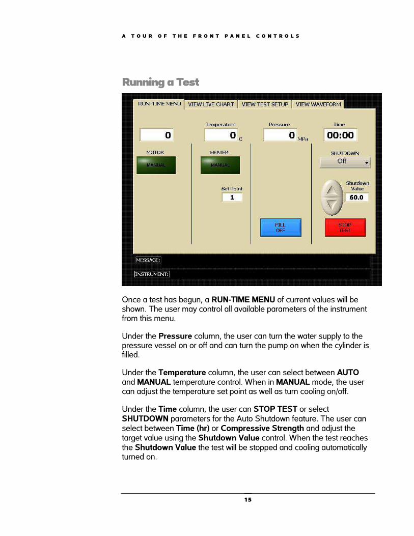
Running a Test
Once a test has begun, a RUN-TIME MENU of current values will be shown. The user may control all available parameters of the instrument from this menu.
Under the Pressure column, the user can turn the water supply to the pressure vessel on or off and can turn the pump on when the cylinder is filled.
Under the Temperature column, the user can select between AUTOand MANUAL temperature control. When in MANUAL mode, the user can adjust the temperature set point as well as turn cooling on/off.
Under the Time column, the user can STOP TEST or select SHUTDOWN parameters for the Auto Shutdown feature. The user can select between Time (hr) or Compressive Strength and adjust the target value using the Shutdown Value control. When the test reaches the Shutdown Value the test will be stopped and cooling automatically turned on.
15

A T O U R O F T H E F R O N T P A N E L C O N T R O L S
By selecting the VIEW LIVE CHART tab at the top of the screen, the user can view real-time data in chart form. From this screen, the user may print the chart at any time by pressing the PRINT button located at the bottom of the screen. (Please note that a printer must be connected to the instrument before trying to print.) Pressing the PRINT button displays the full TEST VIEWER screen where the user may select specific printing options such as header/footer information before printing to any installed printer.
A complete table of numerical data can also be viewed here by selecting the DATA tab located on the left side of the screen in the Test Viewer.
16
A T O U R O F T H E F R O N T P A N E L C O N T R O L S
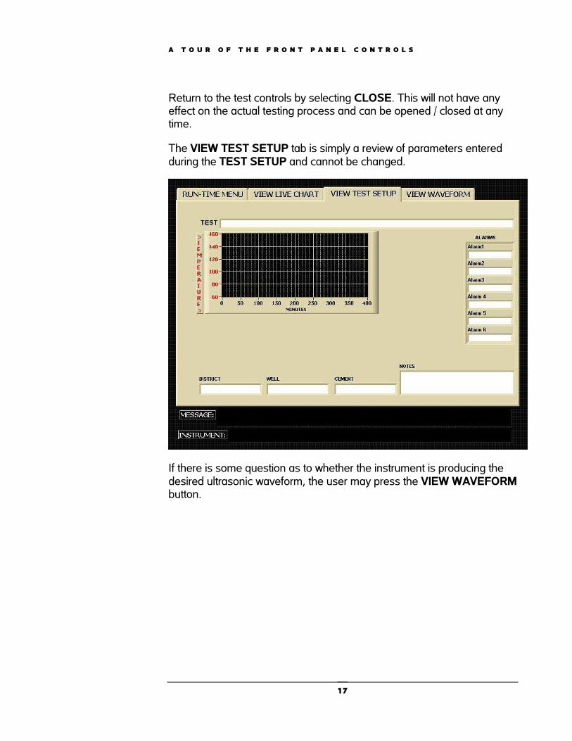
Return to the test controls by selecting CLOSE. This will not have any effect on the actual testing process and can be opened / closed at any time.
The VIEW TEST SETUP tab is simply a review of parameters entered during the TEST SETUP and cannot be changed.
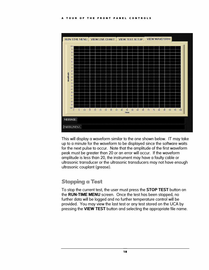
If there is some question as to whether the instrument is producing the desired ultrasonic waveform, the user may press the VIEW WAVEFORMbutton.
17
A T O U R O F T H E F R O N T P A N E L C O N T R O L S
This will display a waveform similar to the one shown below. IT may take up to a minute for the waveform to be displayed since the software waits for the next pulse to occur. Note that the amplitude of the first waveform peak must be greater than 20 or an error will occur. If the waveform amplitude is less than 20, the instrument may have a faulty cable or ultrasonic transducer or the ultrasonic transducers may not have enough ultrasonic couplant (grease).
Stopping a Test To stop the current test, the user must press the STOP TEST button on the RUN-TIME MENU screen. Once the test has been stopped, no further data will be logged and no further temperature control will be provided. You may view the last test or any test stored on the UCA by pressing the VIEW TEST button and selecting the appropriate file name.
18
A T O U R O F T H E F R O N T P A N E L C O N T R O L S
Use of the USB Memory Module The UCA operates under a version of the Windows operating system. This allows the use of certain Universal Serial Bus (USB) peripherals, such as USB flash memory modules. These USB memory modules may be used to archive or move UCA test files to another computer. The USB memory modules may be used without special drivers on any Windows XP or Windows 2000 based PC’s. The memory module will simply appear as another disk drive when inserted into the USB port on the PC.
To archive the stored tests on the UCA to the memory module, follow the steps below.
1. Connect the memory module to the USB port on the UCA control box. No cables are required.
2. Press the ARCHIVE DATA button on the UCA touch screen.
3. Navigate to the USB drive and select the desired save location on the pop-up window.
4. The files will be copied to the USB memory module and deleted from the UCA.
5. Once the files are copied to the USB memory module they may be moved to a desktop PC. Note that once the UCA data files are archived, they are still longer available for retrieval on the UCA. Deleting files from the UCA must be done manually by selecting the files and moving them to the trash bin in Windows.
Networking the Instrument. The UCA may be connected to any Ethernet network (LAN). This makes it convenient to move UCA data files from one computer to another on the network. It is also possible to view a UCA test in progress or an old test from another computer networked to the UCA using the UCA Remote Viewer software. This will allow personnel to view a test in progress from home or on location, provided they have access to the network to which the UCA is connected.
19
A T O U R O F T H E F R O N T P A N E L C O N T R O L S
Since the UCA operates under Windows 98 or later, the instrument can be easily connected to a network. It may be necessary to assign an IP address to the instrument in some instances and this can be done in the usual way through the system setup. The UCA should always be kept behind a secure network firewall to prevent unauthorized access via the internet or other portal. Allowing UCA access via the internet is not recommended.
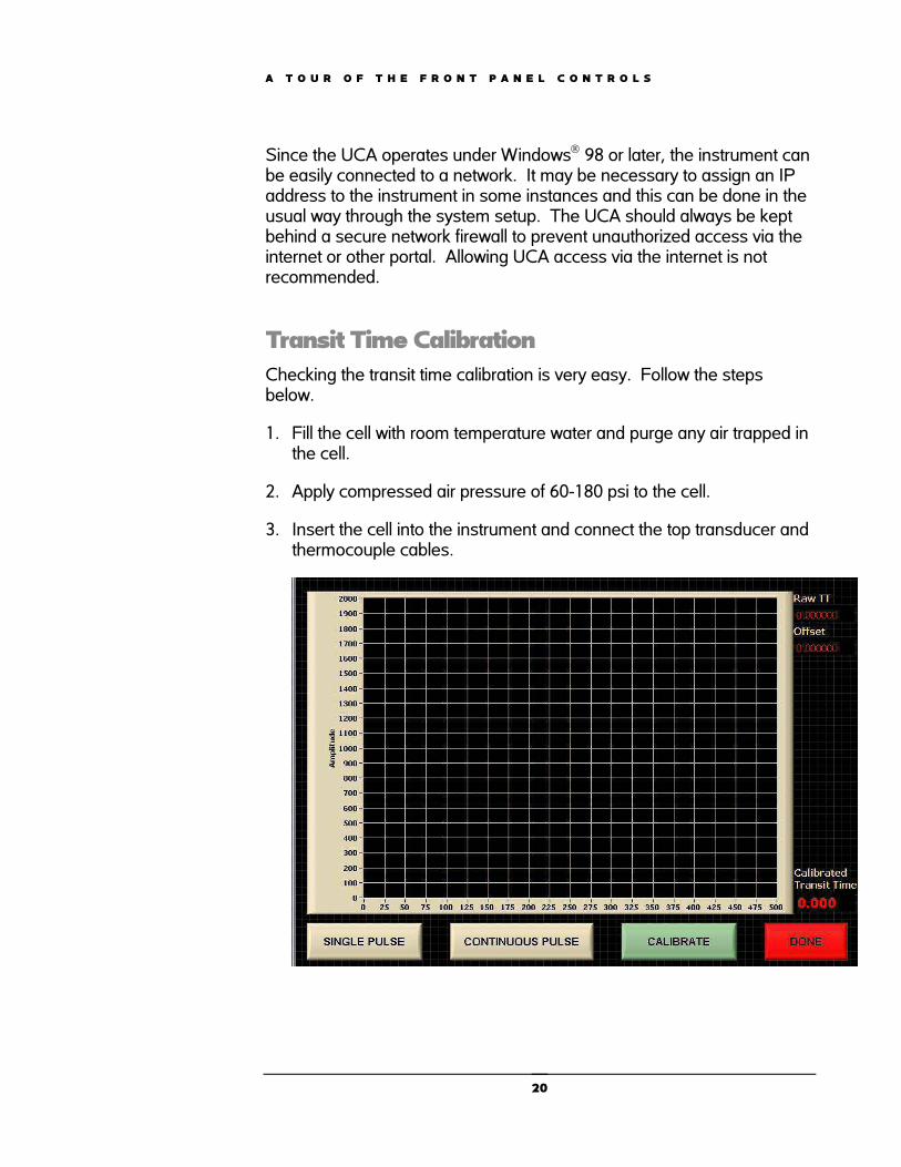
Transit Time Calibration Checking the transit time calibration is very easy. Follow the steps below.
1. Fill the cell with room temperature water and purge any air trapped in the cell.
2. Apply compressed air pressure of 60-180 psi to the cell.
3. Insert the cell into the instrument and connect the top transducer and thermocouple cables.
20
A T O U R O F T H E F R O N T P A N E L C O N T R O L S
4. In Instrument Setup, select CALIBRATE TRANSIT TIME from the touch screen menu. When the calibration screen appears, press the CALIBRATE button. If the waveform appears acceptable, press DONE to save the new calibration values. In general, the peak amplitude should be 600 or greater with water. If an acceptable waveform is not displayed, check the transducers and cables and recalibrate.
Transit time calibration is different from older UCA’s. The steel calibration bar is no longer required. The unit is now calibrated with water. It is imperative that there be no air in the water during calibration or while a test is in progress.
Incorrect or improper calibration values are the most likely reason for the UCA to report incorrect strength values. The calibration should be checked whenever the transducers are removed or if the compressive strength values become suspect.
21
A T O U R O F T H E F R O N T P A N E L C O N T R O L S
A Tour of the Front Panel Controls Chapter 3 will discuss in detail each front panel control found on the UCA.
he sections below will describe the function of each component found on the front panel. The controls can be divided into three categories: hydraulic controls that control the pressure inside the reservoir, pneumatic controls that
control the air pressure to the pump, and the switches that control the electrical components of the instrument.
The Hydraulic Pressure Controls This section consists of the following controls: the PRESSURE RELEASE valve, the PRESSURE REGULATOR, the REGULATOR BYPASS valve, and the WATER SUPPLY switch. Components that make up this section are used to control the flow of water used to pressurize the cylinder.
The PRESSURE RELEASE valve is used to release pressure from the pressurized cylinder. This valve must be closed during testing except when it is necessary to manually release pressure. This valve must also be closed when removing the pressure vessel with cooling water circulating or cooling water may back up and leak out the pressure port in the top of the instrument. The part number for the PRESSURE RELEASE valve is C-0002-1.
The PRESSURE REGULATOR may be used to set the upper limit on the system pressure up to 10,000 psig/680 bar. When the hydraulic force on the regulator exceeds the spring force of the regulator, theregulator valve will open and release pressure until the hydraulic and spring forces balance again. The regulator will then close preventing
Chapter
3
It may be convenient to refer to the piping drawings in Chapter 6 when studying this section.
T
22
A T O U R O F T H E F R O N T P A N E L C O N T R O L S
any additional pressure release until the hydraulic force again exceeds the spring force. Turn the PRESSURE REGULATOR knob clockwise to increase pressure and counterclockwise to reduce pressure. The use of the pump and PRESSURE REGULATOR to control pressure automatically will be discussed in Chapter 4. The PRESSURE REGULATOR part number is C-0078.
The pressure regulator is only usable at pressures up to 10,000 psig/680 bar. If it is necessary to operate the UCA at pressures above 10,000 psig/680 bar, the REGULATOR BYPASS must be turned clockwise to the closed position. For automatic operation at pressures below 10,000 psig/680 bar, the PRESSURE REGULATOR SHUTOFF valve must be turned counterclockwise to the fully open position. The part number for this valve is C-0002-1.
The WATER SUPPLY valve is used to control the flow of water to the pump and test cell. This valve must be closed any time the test cell is not installed. This valve must be open to fill the pressure vessel with water or to operate the pump. Opening this valve when the test cell is not connected will cause a serious water leak.
The Pneumatic Controls The pneumatic section consists of the AIR TO PUMP gauge and the AIR TO PUMP regulator. The components in this section are used to power the air driven hydraulic pump that applies pressure to the sample.
The AIR TO PUMP gauge indicates how much air pressure is being supplied to the instrument. The part number for the AIR PRESSUREgauge is C-0138. If there is no pressure indicated on this gauge, the pump will not operate. The pressure should be between 20 and 100 psig (1.4 and 6.8 bar) when the pump is not in use. It is normal for the inlet air pressure to drop when the pump is in operation. If the air pressure drops significantly and the pump seems unable to achieve the desired pressure, it may be because the compressed air system is not capable of delivering enough air to operate the pump.
The AIR TO PUMP regulator is used to control the air pressure to the air driven hydraulic pump. Higher hydraulic pressures require higher air pressures. To adjust the pressure of the air supplied to the pump,
The pressure gauge displays pressure in both English and SI units.
23
A T O U R O F T H E F R O N T P A N E L C O N T R O L S
pull the knob on the regulator out to unlock it. Turn the regulator knob clockwise to increase the pressure and counterclockwise to decrease the pressure. When the adjustment is finished, push the knob in to lock it in place. The part number of this regulator is C-0021.
This regulator is used to control the pressure of the air supplied to the pump (part number C-0077). The hydraulic pressure output of the pump is directly proportional to the air pressure supplied to the pump. As the air pressure increases, the hydraulic pressures increases and vice versa. Air pressure to the pump may be decreased by turning the AIR TO PUMP regulator knob counterclockwise or increased by turning the knob clockwise. If the regulator is set to a value and the pump switch is turned to the ON position, the pump will increase pressure until the pneumatic force of the air (air pressure multiplied by pneumatic piston area) equals the hydraulic force of the pressurizing water (water pressure multiplied by pump piston area). At this point the hydraulic and pneumatic pressures will be in equilibrium and the pump will cease to stroke. If the water pressure falls for some reason, a force imbalance will be created between the pneumatic and hydraulic sides of the pump and the pump will begin to stroke and increase the hydraulic pressure until it is balanced with the pneumatic pressure, then it will stop pumping. In this way, the pump may be used as a pressure control device (combined with the relief valve) to establish the lower pressure limit for a test. This will be discussed further in Chapter 4.
The Electrical and Electronic Controls and Displays The only front panel electrical controls are the POWER, and WATER SUPPLY switches. These controls are discussed in detail below.
The switch labeled POWER controls electrical power to the entire instrument. Nothing else is operable if this switch is not on. The part number for the POWER switch is C-0075-1.
The WATER SUPPLY switch is used to supply water to the UCA test cell, pump, and cooling water. This switch should be in the ON position when the instrument is running.
If the PUMP AIR PRESSURE drops off significantly when the pump is operating, an air line may be blocked or the compressor may be insufficient to deliver the volume of air required.
24

O P E R A T I O N
Operation Chapter 4 will discuss in detail the steps required to run a compressive strength test. Examples will be provided when necessary.
Preparing the Test Cell The steps that should be used to set up the test cell are listed below.
1. Apply a light coating of grease to the inside of the test cylinder, including the top and bottom plug surfaces that are in contact with the cement slurry. Coating the threads will grease or anti-seize lubricant is also recommended.
2. Screw the bottom plug into the bottom of the pressure cylinder. The top of the cylinder is stamped TOP on the wrench flats.
3. Add cement to the test cell until the proper fill level is obtained using the Slurry Level Gauge (P/N 4-0058). The slurry should touch the lower tab marked WET but not the upper tab marked DRY. Be careful not to get cement into the threads. If cement sets up in the threads it may make plug removal and installation difficult or impossible.
4. Gently pour a small amount of water into cylinder on top of the cement--just enough to reach the water fill line on the Slurry Level Gauge. Try not to mix the water and cement.
5. Screw the top plug in place. Do not tighten with a wrench. Hand tight or hand tight less 1/8 turn is optimal. A small amount of water should come out the pressure or thermocouple port when the top plug is in place.
6. Wipe the cylinder assembly clean and gently place in autoclave chamber. Make certain the electrical contacts in the bottom of the cabinet and plug are free from corrosion and debris. Rotate cylinder clockwise if necessary. To insure the banana connection on the bottom the cylinder assembly has good contact, make certain the test cell is pushed down firmly inside the heating
Chapter
4
Do not overfill the test cell or cement will be forced into the pressure and/or thermocouple ports and plug them.
A small gap between the top and bottom plugs and the cylinder is advisable. Overtightening does not cause better sealing; it only causes plug removal difficulty.
25

O P E R A T I O N
jacket. Do not turn the test cell assembly counterclockwise or the plugs may come unthreaded.
7. Connect the one end of the coaxial cable to the BNC connector on the top plug and the other end to the connector on the rear panel labeled TRANSDUCER.
8. Align pressure port in top plug with high pressure fitting on top of autoclave assembly. Rotate test cell in a clockwise direction only. The top or bottom plugs may come unscrewed if the test cell is rotated counterclockwise.
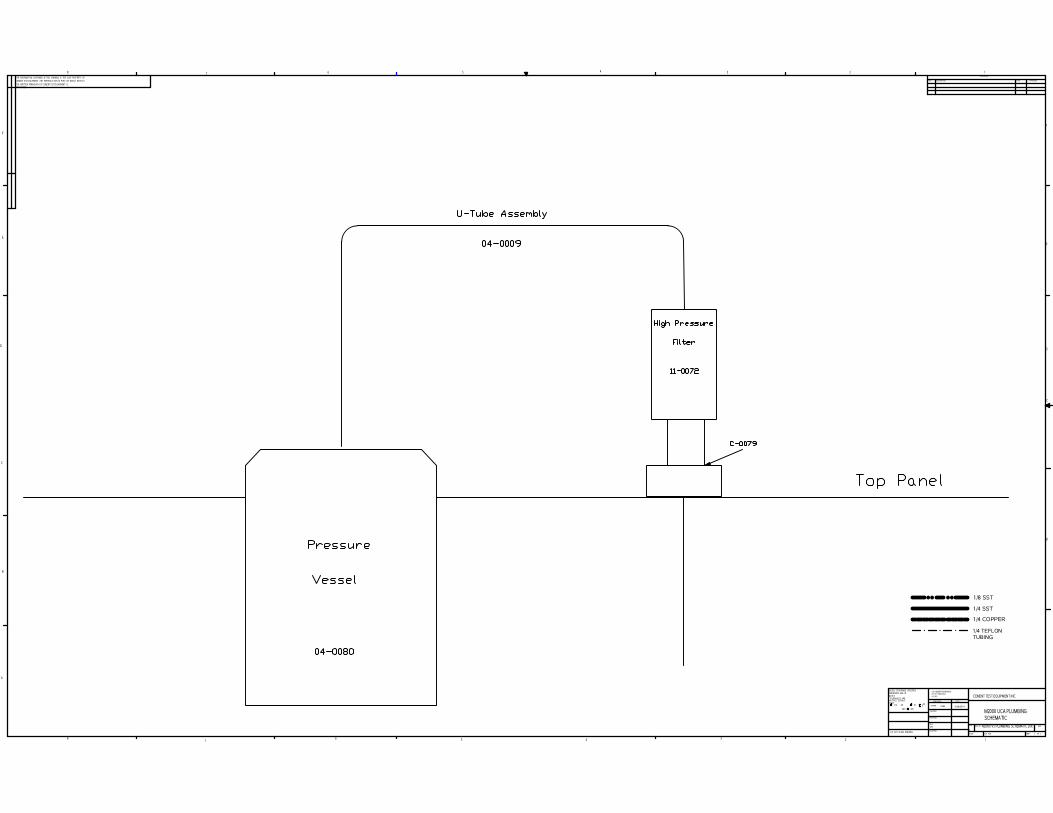
9. Attach the high pressure tube from the cabinet to the test cylinder. Place the U-shaped tube in place. Tighten fittings on both ends of U-tube finger tight only. When the U-shaped tube is in place, complete tightening using a 5/8 inch open end wrench.
10. Connect the thermocouple cable to the connector on the rear of the autoclave labeled J THERMOCOUPLE.
11. Install the thermocouple into the remaining high pressure port in the top plug of the test cell until the fitting is finger tight.
12. Slowly open the water supply valve until water begins to come out the thermocouple connection vent hole. Tighten the thermocouple with a 5/8 inch open end wrench. It is recommended a rag or paper towel be placed near the thermocouple vent hole to collect the spilled water and prevent it from running down inside the instrument or into the sensor cavity.
The instrument is now ready to begin a compressive strength test.
Setting Up a Temperature Ramp See Chapter 2.
Setting Up Automatic Pressure ControlThis section describes the steps used to control pressure in the Model 2000 UCA. Use of the internal pump and pressure regulator will also be discussed.
Follow the steps below the to configure the pump and pressure regulator for automatic pressure control.
26
O P E R A T I O N
1. Make certain the test cylinder is installed properly, the HIGH PRESSURE INLET port on the rear of the instrument (if equipped) is plugged, the PUMP and COOLING WATER is in the ON position in the software and the COOLING WATER is in the OFF position in the software, and the instrument is supplied with compressed air.
2. Turn the AIR TO PUMP regulator clockwise until air pressure is sufficient to raise pressure to the desired pressure set point The air pressure should not exceed 100 psig (690 kPa).
3. Turn the blue PRESSURE REGULATOR knob clockwise until the regulator pressure is sufficient to prevent the regulator from opening at the required pressure set point.
4. Turn the AIR TO PUMP knob clockwise and increase pressure until the pressure exceeds the desired set point. Turn the PUMP switch OFF in the software. Make certain the system is holding pressure before proceeding. The pump contains metal-to-metal inlet and outlet check valves that may not be bubble tight, so a small amount of pressure leakage is to be expected. This should not be a problem under normal operation.
5. Turn the blue PRESSURE REGULATOR knob counterclockwise slowly until the test cylinder pressure begins to drop. Continue turning the regulator knob slowly until the pressure in the test cell is at the upper limit of the desired test pressure.
6. Release pressure in the test cell using the PRESSURE RELEASE valve.
7. Turn the AIR TO PUMP regulator counterclockwise until the AIR TO PUMP is approximately zero.
8. Turn the PUMP switch ON in the software.
9. Slowly turn the PUMP AIR PRESSURE ADJUST regulator knob clockwise until the pump actuates. Continue to slowly turn the regulator knob clockwise until the lower limit for the control pressure is reached.
As the test cylinder gets hot, pressure in the test cylinder will increase. When the pressure in the test cylinder exceeds the control pressure upper set point, the pressure regulator will open and pressure will be reduced. If the heating rate is reduced, as during the transition from a temperature ramp to a temperature soak, the pressure in the test cylinder may decrease. If the pressure falls below the control pressure lower limit, the pump will actuate and bring the pressure back within the established limits.
27
O P E R A T I O N
The pump and pressure regulator will have hysteresis or a “deadband” in their operation. For example, if the pressure regulator is set to open at 3000 psig, it may open at 3000 psig, but may not close until the pressure falls to some lower value, perhaps 2900 psig. This 100 psig differential between opening and closing is referred to as the deadband or hysteresis. As another example, the pump may be set to actuate if the pressure falls to 3000 psig, but the pressure may reach perhaps 3100 psig before the pump stops. This 100 psig differential between the initial pressure and the final pressure is also known as deadband or hysteresis. If the upper and lower set points are too close together, this deadband may overlap and cause system instability. The system will then go into a continuous oscillation where the pump increases pressure and the pressure regulator releases all the pressure the pump is able to build. The solution to this problem is to decrease the lower set point, raise the upper set point, or both.
Stopping a TestWhen the test has been completed, follow the steps below to end the test.
1. Press the STOP TEST button to manually stop a test.
2. Press the COOLING WATER button to cool the test cell. Use the pump to maintain pressure on the test cell until the cell is cool. When the temperature is below 200°F (93°C) the PUMP switch may be turned to the OFF position and the PRESSURE RELEASE valve opened. Failure to maintain pressure at temperatures above 212°F (100°C) may cause water in the test cell to vaporize into steam.
3. Turn WATER SUPPLY switch to its OFF position
4. To shut-down instrument, press EXIT and confirm. Next, press Windows Start button on bottom left of screen and Shut-down computer properly.
5. Turn POWER switch to its OFF position.
6. Close the PRESSURE RELEASE valve (clockwise). Failure to do so will result in water leakage if cooling water is circulating when the U-tube or thermocouple are loosened.
7. Remove the U-shaped high pressure tubing connecting the test cylinder to the bulkhead fitting on the top of the instrument.
8. Disconnect the transducer cable.
28

O P E R A T I O N
9. Disconnect the thermocouple cable.
10. Lift the test cell from the instrument.
The test cylinder is now ready to be cleaned. Cleanup should be done as soon after completion of a test as possible when the sample is easiest to remove.
Cleaning the Test Cell When the test cylinder has been cooled and removed from the instrument, it should be cleaned according the following guidelines.
1. Place the test cylinder in a vice, topside up. The top of the cylinder is marked on the cylinder wrench flats. Use the wrench flats to clamp the plugs and cylinder and do not scratch or nick the cylinder or plugs.
2. Remove the cylinder from the vice and replace in the vice top side down.
3. Unscrew and remove the bottom plug from the test cylinder.
4. Turn the cylinder over and tap the cement sample out of the test cell with a hammer. The cylinder is tapered outward from top to bottom so the cement sample must always be removed through the bottom of the cylinder.
5. Clean the cement and grease from the top and bottom plugs and cylinder.
6. When all traces of cement have been removed, grease the inner surfaces of the test cell, including the seals and o-rings.
7. Replace the o-rings if they were damaged during the test.
The test cylinder is now ready to be used for the next test.
Interpreting Test Results An ultrasonic measurement is a nondestructive test method. It predicts relative compressive strength development by comparing transit times of known mechanical compressive strength data to transit times observed in the UCA. Actual data will have points above and below the best fit curve used to develop the algorithm. The closer the slurry being tested is to the actual slurry used to develop the algorithm the closer the data will match.
The spiral retaining ring found on the bottom plug is used to retain the seal ring and o-ring during disassembly. In some cases, it may make removal of the bottom plug more difficult. Its use is strictly optional and may be omitted if desired.
29
O P E R A T I O N
Algorithm A = Lightweight slurry (<14 lb/gal) Algorithm B = NORMAL SLURRY (standard, used on almost all applications and should be the default) Algorithm C = High density slurry (>17.5 lb/gal)
Algorithm A was developed in the 1970’s for use with lightweight slurries. However, some modern lightweight slurries may work better on algorithm B. Most of the modern lightweight slurries react like a standard or normal slurry so algorithm B is typically a better choice. Algorithm A is intended for slurries where fly-ash is the major component. The use of algorithm A is recommended in reduced water slurries. Use algorithm C when there is a weighting agent present to get the density above 17.5 lb/gal.
We recommend performing a mechanical compressive strength test to see what the actual compressive strength is. If the results are within 200 psi then it is considered the correct algorithm. If not, try a different algorithm. You can easily change algorithms using the Test Viewer to see which algorithm best fits your data.
The algorithms developed by Halliburton in the 1970's used data from cement cured at elevated temperatures rather than below ambient temperatures. Algorithms are being extrapolated to a certain extent at lower temperatures. Modern slurry of a certain density may be better represented with a different algorithm than a slurry from 40+ years ago. Having strength values compute a bit low just makes for conservative results. Ordinarily, CTE recommends customers use algorithm B unless they have reason to think another algorithm might work better. If the crush data seems to indicate that algorithm A fits a slurry better than algorithm B, then there is no reason not to use algorithm A.
The strength values obtained using either the API/ISO crush test or the UCA are indicative of the integrity of the cement under uniaxial loading. In the wellbore, the cement is subject to complex triaxial loading, and the failure stresses may be substantially different from those observed in the standard compressive strength test.
30
M A I N T E N A N C E A N D T R O U B L E S H O O T I N G
Maintenance and Troubleshooting This chapter contains information about the necessary periodic maintenance of the instrument as well as common service and troubleshooting guidelines.
Maintenance CA’s can be relatively reliable and trouble free—provided they are serviced and maintained properly. Instruments that are neglected and receive infrequent service or are subject to abuse are certain to cause trouble. The maintenance requirements for UCA are very
simple and should consume little time.
The first maintenance item is to check and replace the 2 micron filter element inside the high pressure filter housing periodically. The filter housing is located on top of the instrument cabinet and is connected to the high pressure tubing leading to the test cylinder. The filter housing should be thoroughly cleaned at this time. The high pressure filter is designed to prevent cement particles from entering the PRESSURE REGULATOR and damaging it.
The second maintenance item is to thoroughly clean and lubricate the test cylinder after every test. Be sure to inspect the o-rings for damage and replace if damaged or severely distorted.
It is recommended that the thermocouple and water line connections on the top plug be cleaned periodically to prevent buildup of cement in the bore and threads.
Chapter
5
U
31

M A I N T E N A N C E A N D T R O U B L E S H O O T I N G
Periodically inspect the electrical connector in the bottom of the instrument where the test cylinder rests. If this connector becomes dirty or corroded, the lower transducer may not make good electrical contact. Clean the connector if necessary.
Unlike other UCA’s, it is not necessary to coat the ultrasonic transducers with couplant prior to every test. In fact, the transducers should not be removed unless they are believed to be faulty or unless they need additional couplant. The top transducer is sealed to prevent water from entering the transducer chamber during cylinder filling or cleanup.
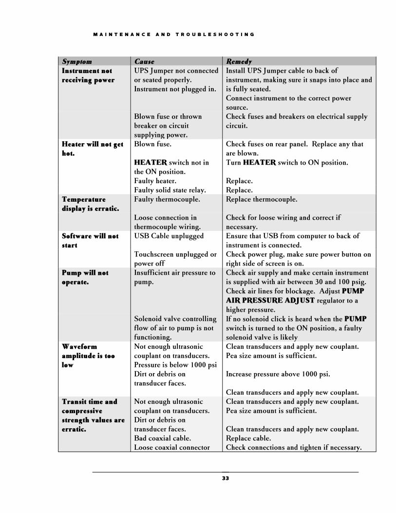
Troubleshooting The following section consists of a table listing possible remedies for the most common UCA problems.
Symptom Cause RemedySystem builds pressure but will not hold pressure
Leak
TESCOM Regulator Leaking
Check fittings for leaks and tighten fittings. Rebuild regulator or replace.
PRESSURE RELEASEvalve is not closed tightly
Close valve tightly.
PRESSURE RELEASEvalve is worn out.
Replace valve stem or entire valve.
POWER circuit breaker switch trips off
Short circuit is system wiring.
Disconnect power to instrument and check for short circuits with an ohm meter.
Faulty POWER switch. Replace switch.Pump strokes but little or no pressure is obtained
PRESSURE RELEASEvalve open, severe leak, blown rupture disc.
Locate problem and correct.
Test cylinder has trapped air.
Open thermocouple connector slightly and release trapped air.
WATER SUPPLY valve is not open or water is not being supplied to the instrument.
Open WATER SUPPLY valve and check flow of water to the instrument.
PRESSURE REGULATOR is not holding pressure.
Turn PRESSURE REGULATOR knob clockwise. Overhaul/replace regulator.
Faulty pump check valve. Clean and/or overhaul pump check valves.
Problems related to corrosion of the lower transducer connection can be minimized by not allowing water to run down the side of the cylinder and into the bottom of the instrument.
32
M A I N T E N A N C E A N D T R O U B L E S H O O T I N G
Symptom Cause RemedyInstrument not receiving power
UPS Jumper not connected or seated properly. Instrument not plugged in.
Install UPS Jumper cable to back of instrument, making sure it snaps into place and is fully seated. Connect instrument to the correct power source.
Blown fuse or thrown breaker on circuit supplying power.
Check fuses and breakers on electrical supply circuit.
Heater will not get hot.
Blown fuse. Check fuses on rear panel. Replace any that are blown.
HEATER switch not in the ON position.
Turn HEATER switch to ON position.
Faulty heater. Replace.Faulty solid state relay. Replace.
Temperature display is erratic.
Faulty thermocouple. Replace thermocouple.
Loose connection in thermocouple wiring.
Check for loose wiring and correct if necessary.
Software will not start
USB Cable unplugged Ensure that USB from computer to back of instrument is connected.
Touchscreen unplugged or power off
Check power plug, make sure power button on right side of screen is on.
Pump will not operate.
Insufficient air pressure to pump.
Check air supply and make certain instrument is supplied with air between 30 and 100 psig. Check air lines for blockage. Adjust PUMP AIR PRESSURE ADJUST regulator to a higher pressure.
Solenoid valve controlling flow of air to pump is not functioning.
If no solenoid click is heard when the PUMPswitch is turned to the ON position, a faulty solenoid valve is likely
Waveform amplitude is too low
Not enough ultrasonic couplant on transducers. Pressure is below 1000 psi Dirt or debris on transducer faces.
Clean transducers and apply new couplant. Pea size amount is sufficient.
Increase pressure above 1000 psi.
Clean transducers and apply new couplant.Transit time and compressive strength values are erratic.
Not enough ultrasonic couplant on transducers. Dirt or debris on transducer faces. Bad coaxial cable. Loose coaxial connector
Clean transducers and apply new couplant. Pea size amount is sufficient.
Clean transducers and apply new couplant. Replace cable. Check connections and tighten if necessary.
33
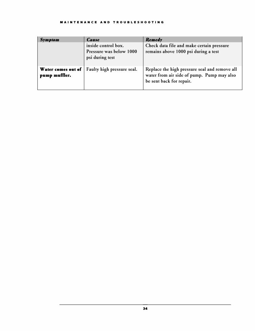
M A I N T E N A N C E A N D T R O U B L E S H O O T I N G
Symptom Cause Remedyinside control box.Pressure was below 1000 psi during test
Check data file and make certain pressure remains above 1000 psi during a test
Water comes out of pump muffler.
Faulty high pressure seal. Replace the high pressure seal and remove all water from air side of pump. Pump may also be sent back for repair.
34
M A I N T E N A N C E A N D T R O U B L E S H O O T I N G
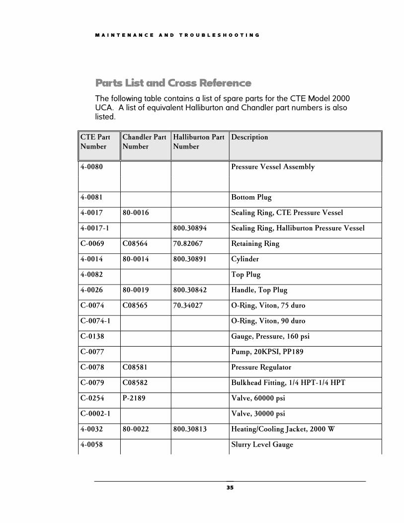
Parts List and Cross Reference The following table contains a list of spare parts for the CTE Model 2000 UCA. A list of equivalent Halliburton and Chandler part numbers is also listed.
CTE Part Number
Chandler Part Number
Halliburton Part Number
Description
4-0080 Pressure Vessel Assembly
4-0081 Bottom Plug
4-0017 80-0016 Sealing Ring, CTE Pressure Vessel
4-0017-1 800.30894 Sealing Ring, Halliburton Pressure Vessel
C-0069 C08564 70.82067 Retaining Ring
4-0014 80-0014 800.30891 Cylinder
4-0082 Top Plug
4-0026 80-0019 800.30842 Handle, Top Plug
C-0074 C08565 70.34027 O-Ring, Viton, 75 duro
C-0074-1 O-Ring, Viton, 90 duro
C-0138 Gauge, Pressure, 160 psi
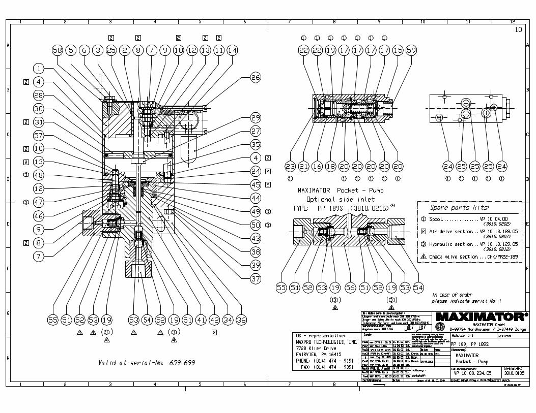
C-0077 Pump, 20KPSI, PP189
C-0078 C08581 Pressure Regulator
C-0079 C08582 Bulkhead Fitting, 1/4 HPT-1/4 HPT
C-0254 P-2189 Valve, 60000 psi
C-0002-1 Valve, 30000 psi
4-0032 80-0022 800.30813 Heating/Cooling Jacket, 2000 W
4-0058 Slurry Level Gauge
35
M A I N T E N A N C E A N D T R O U B L E S H O O T I N G
CTE Part Number
Chandler Part Number
Halliburton Part Number
Description
C-0379 C08566 70.83164 Spring, .72 x .072 x 3.00
4-0035 80-0026 800.30824 Heating Jacket Centering Ring
4-0023 80-0024 800.30823 Heating Jacket End Gasket
4-0037 Heating Jacket Bottom Gasket
4-0085 Transducer Retainer, Top
4-0087 Spacer, Compression, Spring, Top
C-0080 SSR, 240 VAC, 25A, DC Control
C-0132 P-3330 70.80037 SSR, 240 VAC, 25A, AC Control
C-0561 C08570 70.49981 Spring
C08606 70.76017 Adapter, BNC, Male-Male
C-0242 P-2610 70.23701 Fuse, 1/4 A, 250 V, MDL-1/4
C-0266 P-3359 70.73543 Inlet, Electrical, 20 A, 250 VAC
4-0021 80-0021 800.30843 Thermocouple, Type J, 20000 psi
C-0371 C08584 70.75933 Sensor, Ultrasonic Transducer, 400F
C-0371-1 Sensor, Ultrasonic Transducer, 500F
C-0024 Solenoid Valve, 2 Way, Normally Closed
C-0075 P-3388 Switch, ON/OFF Circuit Breaker, 10A
C-0003 P-1075 High Pressure Filter Assembly
C-0081 C08590 Rupture Disc, 22,000 psi
C-0096 Pressure Transducer
C-0358 Filter Element, 2 micron
C-0467 Fuse, 20A
C-0481 Power Supply
C-0156 Power Cord
36
M A I N T E N A N C E A N D T R O U B L E S H O O T I N G
CTE Part Number
Chandler Part Number
Halliburton Part Number
Description
4-0065 Cylinder Wrench
C-0842 Monitor, Touch Screen
C-1192-9” Touch Screen Pedestal Mount
04-0110 Assy, Coax Cable, UCA Top Plug
04-0110-1 Assy, Coax Cable, UCA Top Plug, Halliburton
04-0131 84-0057 Assy, Coax Cable, UCA Top Plug Chandler
37

SECTION A-ASCALE 1 : 1
6-11-996-11-996-11-996-11-99
6
8
7
2
4
15
9
10
10
9
4
12
11
12
3
17
18
1919
13
1
5
14
NOTE:04-0080 TOP PLUG CABLE ASSEMBLY INCLUDES 04-0088, C-0395-1, COAX CABLE AND BNC CONNECTORS, AND C-0172 CONNECTOR WITH TEFLON FERRULES.
21
232022
SEE NOTE
ITEM NO. QTY PART NO. DESCRIPTION1 1 4-0014 CYLINDER2 1 4-0081 BOTTOM PLUG3 1 4-0082 TOP PLUG4 2 C-0371 ULTRASONIC TRANSDUCER5 1 4-0036 HEATER TABLE6 1 4-0089 RECEPTACLE, BANANA JACK7 1 4-0085 JACK SUPPORT8 1 4-0086 JACK INSULATOR9 2 4-0017 SEAL RING
10 2 C-0074 O-RING11 1 4-0088d CONNECTOR BASE12 2 4-0026 HANDLE13 1 4-0083 PLUG HOLDER14 1 4-0087B BANANA JACK15 1 4-0084b PLUG INSULATOR17 1 C-0753 O-RING (NOT SHOWN)18 1 C-0127 O-RING (NOT SHOWN)19 2 C-0069 RETAINING RING (NS)20 1 C-0395 SPRING (NOT SHOWN)21 2 C-0393 DOWEL PIN22 1 C-0395-1 SPRING (NOT SHOWN)23 1 04-0087-2 NUT, BANANA JACK (NS)
04-0080
M2000 UCA CYLINDERASSEMBLY
6-11-99
D
C
B
AA
B
C
D
CEMENT TEST EQUIPMENT, INC.CAD GENERATED DRAWING,DO NOT MANUALLY UPDATE
SCALE
SIZE
CAD FILE:
DWG. NO.B
SHEET 1 OF 1
REV.
DATEAPPROVALS
DRAWN
CHECKED
RESP ENG
MFG ENG
QUAL ENG
UNLESS OTHERWISE SPECIFIEDDIMENSIONS ARE IN INCHESTOLERANCES ARE:
FRACTIONS DECIMALS ANGLES
1/32 .XX .01 1.XXX .005
MATERIAL
FINISH
12345678
8 7 6 5 4 3 2 1THE INFORMATION CONTAINED IN THIS DRAWING IS THE SOLE PROPERTY OFCEMENT TEST EQUIPMENT, INC. ANY REPRODUCTION IN PART OR WHOLE WITHOUTTHE WRITTEN PERMISSION OF CEMENT TEST EQUIPMENT, INC. IS PROHIBITED.
CCDCCDCCDCCDCCD
D

A
A
SECTION A-A
2 31 5 4
ITEM NO. PART NUMBER DESCRIPTION QTY.1 11-0072 FILTER HOUSING 1
2 11-0073 FILTER SEAT 1
3 11-0074 SEAT RETAINER 1
4 2-0075 FILTER NIPPLE 1
5 C-0586 FILTER ELEMENT 1
REVISIONS
REV. DESCRIPTION DATE APPROVED
A ADDED NIPPLE AND ELEMENT TO DRAWING 6/23/2014 GRH
12345678
D
C
B
AA
B
C
D
8 7 6 5 4 3 2 1
ADO NOT SCALE DRAWING
11-0070
7/29/08JB
UNLESS OTHERWISE SPECIFIED:
SCALE:1:1 WEIGHT:
REVDWG. NO.
BSIZE
TITLE:
Cement Test EquipmentNAME DATE
COMMENTS:
Q.A.
MFG APPR.
ENG APPR.
CHECKED
DRAWN
SSFINISH
MATERIAL
INTERPRET GEOMETRICTOLERANCING PER:
DIMENSIONS ARE IN INCHESTOLERANCES:FRACTIONAL 1/32ANGULAR: 1TWO PLACE DECIMAL .01THREE PLACE DECIMAL .005
SHEET 1 OF 1
PROPRIETARY AND CONFIDENTIALTHE INFORMATION CONTAINED IN THIS DRAWING IS THE SOLE PROPERTY OF CTE, Inc. ANY REPRODUCTION IN PART OR AS A WHOLE WITHOUT THE WRITTEN PERMISSION OF CTE, Inc. IS PROHIBITED.
Filter Assembly


M2000 UCA PLUMBING SCHEMATIC
M2000 V5 PLUMBING SCHEMATIC 20K
D
C
B
A
B
C
D
CAD GENERATED DRAWIN G,DO NO T MAN UALLY UPD ATE
SCALE
SIZE
C AD FILE:
DWG . NO .
DSHEET 2 OF 2
R EV.
DATEAPPR OVALS
DRAWN
CHECKED
RESP ENG
MFG ENG
Q UAL ENG
UNLESS OT HERWISE SPECIF IEDDIMENSIONS ARE IN INCHES
TOLERANCES ARE:FRACTION S DECI MALS ANG LES
1/32 .XX .01
.XXX .005
DO NOT SCALE DRAWING
12345678
8 7 6 5 4 3 2 1THE INFORMATION CONTAINED IN THIS DRAWING IS THE SOLE PROPERTY OFCEMENT TEST EQUIPMENT. ANY REPRODUCTION IN PART OR WHOLE WITHOUTTHE WRITTEN PERMISSIO N OF CEMENT T EST EQUIPMENT IS PROHIBITED.
REVISI ONS
REV. DESCRIPTION D ATE APPROVED
E
F
E
F
CEMENT TEST EQUIPMENT INC.
1/4 SST
1/8 SST
1/4 COPPER
JPM 8/28/2014
1/4 TEFLONTUBING

EXPLODED LEVEL BOM PIC LIST REPORT
P/B ITEM BOM/PART NUMBER DESCRIPTION LOCATEQUANTITY
PER ASSY
QUANTITY
REQUIREDUNIT
QTY
ISSUED
CEMENT TEST EQUIPMENT, INC.BOM NUMBER :04-0001-1
BOM DESCRIPTION :Assy, UCA Acc & Spares (common)
DATE :06/15/2015 11:48:10 AMQTY :1.0000
CUSBOMPICNOMODEL.F
PAGE NO:1
1.0000 1.0000 Ea
1.0000 1.0000 ASSY
1.0000 1.0000 Ea
1.0000 1.0000 EA
1.0000 1.0000 Ea
1.0000 1.0000 Ea
1.0000 1.0000 Ea
2.0000 2.0000 Ea
2.0000 2.0000 Ea
1.0000 1.0000 EA
25.0000 25.0000 ft
04-0065-1 BOM 0005
04-0071-U PART 0036
C-0156 BOM 0007
C-0275 PART 0010
c-0362-1 PART 0022
C-0595 PART 0023
C-0596 PART 0040
C-0670 PART 0038
PART 0018 C-0765
PART 0041 C-0796
PART 0032 C-1076
PART 0035 M-0009
Wrench, Handy Dandy Multi-Use
Assy, Control Box, v5 UCA
Cord, power, 3 x 14, 15A, 120VAC
Assy, Power Cord, 3FT
Cable Extension, TC, M-F
Cable, USB maleA-maleB, 3'
Printer
Grease, High Temp Red
Cable assy, coax, 6 ft
Lubricant, Copper Antiseize
Hose, rubber, 3/8" ID, 5/8" OD
Tubing Polyurethane, Blue, 1/4" 25.0000 25.0000 ft
EXPLODED LEVEL BOM PIC LIST REPORT
P/B ITEM BOM/PART NUMBER DESCRIPTION LOCATEQUANTITY
PER ASSY
QUANTITY
REQUIREDUNIT
QTY
ISSUED
CEMENT TEST EQUIPMENT, INC.BOM NUMBER :04-0002 REV:
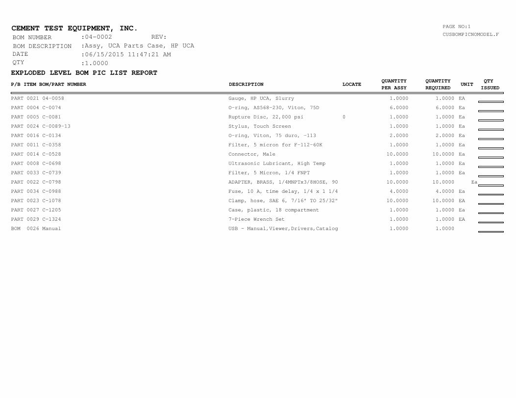
BOM DESCRIPTION :Assy, UCA Parts Case, HP UCA
DATE :06/15/2015 11:47:21 AMQTY :1.0000
CUSBOMPICNOMODEL.F
PAGE NO:1
PART 0021 04-0058 Gauge, HP UCA, Slurry 1.0000 1.0000 EA
PART 0004 C-0074 O-ring, AS568-230, Viton, 75D 6.0000 6.0000 Ea
PART 0005 C-0081 Rupture Disc, 22,000 psi 0 1.0000 1.0000 Ea
PART 0024 C-0089-13 Stylus, Touch Screen 1.0000 1.0000 Ea
PART 0016 C-0134 O-ring, Viton, 75 duro, -113 2.0000 2.0000 Ea
PART 0011 C-0358 Filter, 5 micron for F-112-60K 1.0000 1.0000 Ea
PART 0014 C-0528 Connector, Male 10.0000 10.0000 Ea
PART 0008 C-0698 Ultrasonic Lubricant, High Temp 1.0000 1.0000 Ea
PART 0033 C-0739 Filter, 5 Micron, 1/4 FNPT 1.0000 1.0000 Ea
PART 0022 C-0798 ADAPTER, BRASS, 1/4MNPTx3/8HOSE, 90 10.0000 10.0000 Ea
PART 0034 C-0988 Fuse, 10 A, time delay, 1/4 x 1 1/4 4.0000 4.0000 Ea
PART 0023 C-1078 Clamp, hose, SAE 6, 7/16" TO 25/32" 10.0000 10.0000 EA
PART 0027 C-1205 Case, plastic, 18 compartment 1.0000 1.0000 Ea
PART 0029 C-1324 7-Piece Wrench Set 1.0000 1.0000 EA
BOM 0026 Manual USB - Manual,Viewer,Drivers,Catalog 1.0000 1.0000

EXPLODED LEVEL BOM PIC LIST REPORT
P/B ITEM BOM/PART NUMBER DESCRIPTION LOCATEQUANTITY
PER ASSY
QUANTITY
REQUIREDUNIT
QTY
ISSUED
CEMENT TEST EQUIPMENT, INC.BOM NUMBER :04-0001-2
BOM DESCRIPTION :Assy, Dual UCA Accessories
DATE :06/15/2015 02:00:25 PMQTY :1.0000
CUSBOMPICNOMODEL.F
PAGE NO:1
2.0000 2.0000
1.0000 1.0000 Ea
2.0000 2.0000 ASSY
2.0000 2.0000 Ea
2.0000 2.0000 Ea
2.0000 2.0000 Ea
4.0000 4.0000 Ea
1.0000 1.0000 EA
25.0000 25.0000 ft
25.0000 25.0000 ft
BOM 0031 04-0055-2
PART 0020 04-0065-1
BOM 0005 04-0071-U
PART 0010 c-0362-1PART 0022 C-0595
PART 0023 C-0596
PART 0039 C-0670-1
PART 0018 C-0765
PART 0040 C-0796
PART 0032 C-1076
PART 0037 M-0009
PART 0007 M-0058
Assy, Bracket UCA, 12"
Wrench, Handy Dandy Multi-Use
Assy, Control Box, v5 UCA
Cable Extension, TC, M-F Cable,
USB maleA-maleB, 3' Printer
PRINTERGrease/Antiseize, White PTFE
Cable assy, coax, 6 ft
Lubricant, Copper Antiseize
Hose, rubber, 3/8" ID, 5/8" OD
Tubing Polyurethane, Blue, 1/4"
POWER CABLE, MAIN 12.5000 12.5000 FT
1.0000 EA1.0000 EA

MAXIMATOR®
MAXIMATOR GmbH37449 Zorge, Walkenrieder Str. 15, Tel.: ++49 (0) 5586 803 0, Fax: ++49 (0) 5586 803 40 Technische Änderungen vorbehaltene-mail: [email protected], website: www.maximator.de
MAXIMATOR®
MAXIMATOR GmbH37449 Zorge, Walkenrieder Str. 15, Tel.: ++49 (0) 5586 803 0, Fax: ++49 (0) 5586 803 40e-mail: [email protected], website: www.maximator.de
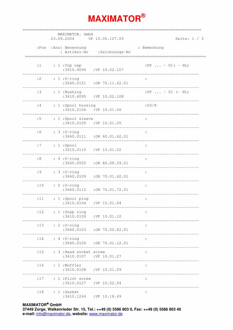
============================================================================
MAXIMATOR. GmbH
23.09.2004 VP 10.00.127.05 Seite: 1 / 3
:Pos :Anz: Benennung : Bemerkung
: Artikel-Nr :Zeichnungs-Nr
=============================================================================
:1 : 1 :Top cap :PP ... - 01( - HL)
:3610.4094 :VP 10.02.107
---------------------------------------------------------------------------
:2 : 1 :O-ring :
:3660.0151 :OR 70.11.42.01
---------------------------------------------------------------------------
:3 : 1 :Bushing :PP ... - 01 (- HL)
:3610.4095 :VP 10.02.108
---------------------------------------------------------------------------
:4 : 1 :Spool housing :G3/8
:3610.0106 :VP 10.01.06
---------------------------------------------------------------------------
:5 : 1 :Spool sleeve :
:3610.0105 :VP 10.01.05
---------------------------------------------------------------------------
:6 : 3 :O-ring :
:3660.0111 :OR 60.01.62.01
---------------------------------------------------------------------------
:7 : 1 :Spool :
:3610.0110 :VP 10.01.02
---------------------------------------------------------------------------
:8 : 4 :O-ring :
:3660.0505 :OR 80.08.39.01
---------------------------------------------------------------------------
:9 : 3 :O-ring :
:3660.0109 :OR 70.01.42.01
---------------------------------------------------------------------------
:10 : 2 :O-ring :
:3660.0112 :OR 70.01.72.01
---------------------------------------------------------------------------
:11 : 1 :Spool plug :
:3610.0104 :VP 10.01.04
---------------------------------------------------------------------------
:12 : 1 :Snap ring :
:3610.0109 :VP 10.01.10
---------------------------------------------------------------------------
:13 : 2 :O-ring :
:3660.0103 :OR 70.00.82.01
---------------------------------------------------------------------------
:14 : 4 :O-ring :
:3660.0106 :OR 70.01.12.01
---------------------------------------------------------------------------
:15 : 3 :Head socket screw :
:3610.0107 :VP 10.01.07
---------------------------------------------------------------------------
:16 : 1 :Muffler :
:3610.0108 :VP 10.01.09
---------------------------------------------------------------------------
:17 : 1 :Pilot screw :
:3610.0127 :VP 10.02.04
---------------------------------------------------------------------------
:18 : 1 :Gasket :
:3610.1264 :VP 10.18.49
MAXIMATOR®
MAXIMATOR GmbH37449 Zorge, Walkenrieder Str. 15, Tel.: ++49 (0) 5586 803 0, Fax: ++49 (0) 5586 803 40e-mail: [email protected], website: www.maximator.de
============================================================================
MAXIMATOR. GmbH
23.09.2004 VP 10.00.127.05 Seite: 2 / 3
:Pos :Anz: Benennung : Bemerkung
: Artikel-Nr :Zeichnungs-Nr
=============================================================================
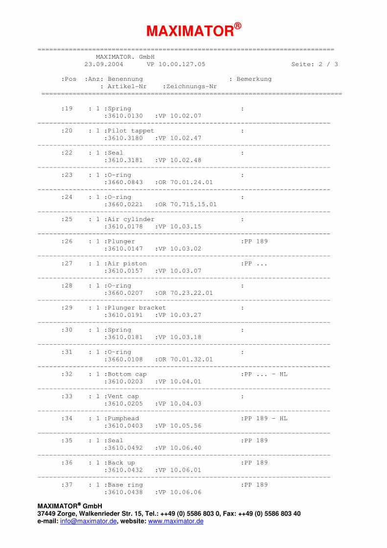
:19 : 1 :Spring :
:3610.0130 :VP 10.02.07
---------------------------------------------------------------------------
:20 : 1 :Pilot tappet :
:3610.3180 :VP 10.02.47
---------------------------------------------------------------------------
:22 : 1 :Seal :
:3610.3181 :VP 10.02.48
---------------------------------------------------------------------------
:23 : 1 :O-ring :
:3660.0843 :OR 70.01.24.01
---------------------------------------------------------------------------
:24 : 1 :O-ring :
:3660.0221 :OR 70.715.15.01
---------------------------------------------------------------------------
:25 : 1 :Air cylinder :
:3610.0178 :VP 10.03.15
---------------------------------------------------------------------------
:26 : 1 :Plunger :PP 189
:3610.0147 :VP 10.03.02
---------------------------------------------------------------------------
:27 : 1 :Air piston :PP ...
:3610.0157 :VP 10.03.07
---------------------------------------------------------------------------
:28 : 1 :O-ring :
:3660.0207 :OR 70.23.22.01
---------------------------------------------------------------------------
:29 : 1 :Plunger bracket :
:3610.0191 :VP 10.03.27
---------------------------------------------------------------------------
:30 : 1 :Spring :
:3610.0181 :VP 10.03.18
---------------------------------------------------------------------------
:31 : 1 :O-ring :
:3660.0108 :OR 70.01.32.01
---------------------------------------------------------------------------
:32 : 1 :Bottom cap :PP ... - HL
:3610.0203 :VP 10.04.01
---------------------------------------------------------------------------
:33 : 1 :Vent cap :
:3610.0205 :VP 10.04.03
---------------------------------------------------------------------------
:34 : 1 :Pumphead :PP 189 - HL
:3610.0403 :VP 10.05.56
---------------------------------------------------------------------------
:35 : 1 :Seal :PP 189
:3610.0492 :VP 10.06.40
---------------------------------------------------------------------------
:36 : 1 :Back up :PP 189
:3610.0432 :VP 10.06.01
---------------------------------------------------------------------------
:37 : 1 :Base ring :PP 189
:3610.0438 :VP 10.06.06

MAXIMATOR®
MAXIMATOR GmbH37449 Zorge, Walkenrieder Str. 15, Tel.: ++49 (0) 5586 803 0, Fax: ++49 (0) 5586 803 40e-mail: [email protected], website: www.maximator.de
============================================================================
MAXIMATOR. GmbH
23.09.2004 VP 10.00.127.05 Seite: 3 / 3
:Pos :Anz: Benennung : Bemerkung
: Artikel-Nr :Zeichnungs-Nr
=============================================================================
:38 : 1 :Lock nut :
:3610.0444 :VP 10.06.12
---------------------------------------------------------------------------
:39 : 1 :Cap nut :
:3610.0443 :VP 10.06.11
---------------------------------------------------------------------------
:40 : 2 :Ball bracket :
:3610.0397 :VP 10.05.50
---------------------------------------------------------------------------
:41 : 2 :Spring :
:3610.0399 :VP 10.05.52
---------------------------------------------------------------------------
:42 : 2 :Ball :
:3610.0358 :VP 10.05.16
---------------------------------------------------------------------------
:43 : 1 :Inlet gland :3/8NPT
:3610.0420 :VP 10.05.69
---------------------------------------------------------------------------
:44 : 1 :Outlet gland :9/16-18UNF
:3610.0424 :VP 10.05.71
---------------------------------------------------------------------------
:45 : 1 :Mounting bracket (bottom) :
:3610.0182 :VP 10.03.19
---------------------------------------------------------------------------
:46 : 4 :Hex head screw :
:3610.1069 :VP 10.15.02
---------------------------------------------------------------------------
:47 : 2 :U-Washer :
:3610.0185 :VP 10.03.21
---------------------------------------------------------------------------
:48 : 4 :Spring washer :
:3610.0184 :VP 10.03.20
---------------------------------------------------------------------------
:50 : 1 :Pumphead w. side inlet :Optional type: PP 189S - HL
:3610.0405 :VP 10.05.58
---------------------------------------------------------------------------
:51 : 1 :Cover plate :drop at PP 189 - HL !
:3610.0128 :VP 10.02.05
---------------------------------------------------------------------------
:52 : 1 :Hex head screw :drop at PP 189 - HL !
:3610.0129 :VP 10.02.06
---------------------------------------------------------------------------
:53 : 1 :Adapter :1/4NPT
:3620.0160 :VP 15.02.32
---------------------------------------------------------------------------
:54 : 1 :O-ring :
:3660.1112 :OR 70.04.46.01
---------------------------------------------------------------------------

MAXIMATOR®
MAXIMATOR GmbH37449 Zorge, Walkenrieder Str. 15, Tel.: ++49 (0) 5586 803 0, Fax: ++49 (0) 5586 803 40e-mail: [email protected], website: www.maximator.de
MAXPRO ÄnderungsprotokollMAXPRO Record of changes
Typ: PP 189(S) – 01(-HL)Type:
Zeichnungs-Nr.: VP 10.00.127.05Drawing-No.
Artikel-Nr.: 3810.0192 / 3810.0170Ident-No.
Änderungsdatum: 23.09.2004Date of change
Änderungshinweise: - HD-Dichtsatz war VP 10.13.129.01 (3610.0808) ersetzt durchChange directions HD-Dichtsatz VP 10.13.129.05 (3610.0812)
- HP-seal kit VP 10.13.129.01 (3610.0808) removed throughHP-seal kit VP 10.13.129.05 (3610.0812)


