M 890-00559 rev.03 Rev.03 M2000, M4000 & M8000 Variable Output Module User’s manual M8000 2 3 4 5 6 7 8 9 10 Auto 1 CIRCUIT 2 Off Auto (Variable) On (100%) Off Auto (Variable) On (100%) Off Auto (Variable) On (100%) Off Auto (Variable) On (100%) 0.5’’ 0.5’’ 0.5’’ CIRCUIT 1 CIRCUIT 2 CIRCUIT 3 CIRCUIT 4
Transcript
M 890-00559 rev.03 Rev.03
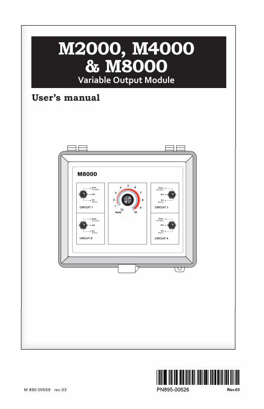
M2000, M4000 & M8000
Variable Output Module
User’s manual
M8000
2
3
45
6
7
8
9
10Auto
1
CIRCUIT 2
Off
Auto (Variable)
On(100%)
Off
Auto (Variable)
On(100%)
Off
Auto (Variable)
On(100%)
Off
Auto (Variable)
On(100%)
0.5’’ 0.5’’
0.5’’
CIRCUIT 1
CIRCUIT 2
CIRCUIT 3
CIRCUIT 4
WARNINGSThe warranty can be void if this product is used in a manner not specified by the manufacturer.
Every effort has been made to ensure that this manual is complete, accurate and up-to-date. The information con-tained in it is however subject to change without notice due to further developments.
For Customer Use: Enter below the serial num-ber located on the side of the alarm system and keep this information for future reference.
4. WIRING ........................................ 64.1. Connect Module to Controller .............. 74.2. Connect Module to Time Clock or
Thermostat ................................... 7
5. SETTINGS ..................................... 85.1. Choosing a Motor Curve ................. 95.2. Choosing a Light Curve ................. 105.3. Setting Sunrise/Sunset ................. 115.4. Selecting the Type of Input ........... 125.5. Selecting the Type of Controller ..... 125.6. Status LED .................................. 12
Safety may be jeopardized if the equipment is used in a manner not specified by the manufacturer. Carefully read and keep the following instructions for future reference.
The room temperature where the module is located must always remain between 32°F and 104°F (0°C to 40°C). Indoor use only!
To avoid exposing the module to harmful gases or excessive humidity, it is preferable to install it in a corridor.
If the equipment is used in a manner not specified by the manufacturer, the protection provided by the equipment may be impaired.
Do not spray water on the module! In order to clean the control, wipe it with a damp cloth.
Before servicing or cleaning unit, switch power off at service panel and lock the switch disconnecting means to prevent power from being switched accidentally. When the service disconnecting means cannot be locked, securely fasten a prominent warning device, such as a tag, to the service panel.
1.2. Product OverviewThe Variable Output Module is used to vary the intensity of some loads in a livestock building. It has been designed to accommo-date various models of fan motors, of heaters (mats or lamps) and light outputs (dimmable compact fluorescent lights (CFL), dimmable cold cathode fluorescent lamps (CCFL) and incandescent lights).
Depending on the model, the module can drive one, two or four 1600W (or 2HP) circuits.
The circuits of a given module can all be con-trolled the same way by an external control system or they can be regulated separately with a combination of control systems.
Below is a list of all possible control sys-tems that can regulate the circuit(s) of your module:
- 0-10V output of an environment controller;- Variable output of an environment controller;- Time clock or thermostat;
2. MOUNTING INSTRUC-TIONS
Open the latch and lift the cover. Remove the black caps located on each of the four mounting holes. Mount the enclosure on the wall using four screws. Be sure the electrical knockouts are at the bottom of the enclosure in order to prevent water from entering the controller. Insert the screws in the mounting holes and tighten. Fasten the four black caps provided with the controller onto the four mounting holes.
The enclosure must be mounted in a location that will allow the cover to be completely opened right up against the wall.
5M8000, M4000 & M2000 rev.03
M8000, M4000 & M2000
3. USER INTERFACE
3.1. Override SwitchThe override switch allows bypassing all com-mands given by the main control system to the output. This switch also has priority over the potentiometer.
Auto (variable) — This position enables the potentiometer (see next section).
Off — The output(s) turn off.
On — The output is supplied by full AC current.
Off
Auto(Variable)
On (100%)
Figure 1. Override Switch & Potentiometer
2
34 5 6
7
8
910Auto
1
Dimmer1-10
Automatic Control
Override Switch Potentiometer
3.2. PotentiometerThe potentiometer allows changing the inten-sity of the outputs manually. It only works on the circuits whose override switches are at“Auto (variable)” position.
The potentiometer only works when the Override Switch is at “Auto (variable)” position.
Automatic Control — While the knob is at “AUTO” position, control of the output(s) is returned to the main control system. If the module is controlled by a time clock or by a thermostat, the “AUTO” position will simply turn the output(s) Off.
Dimmer 1-10 — If the Override switch is at the “AUTO” position, you can use the poten-tiometer to change intensity of the output(s) manually. This will bypass the commands given by the main control system.
6 M8000, M4000 & M2000 rev.03
M8000, M4000 & M2000
4. WIRING
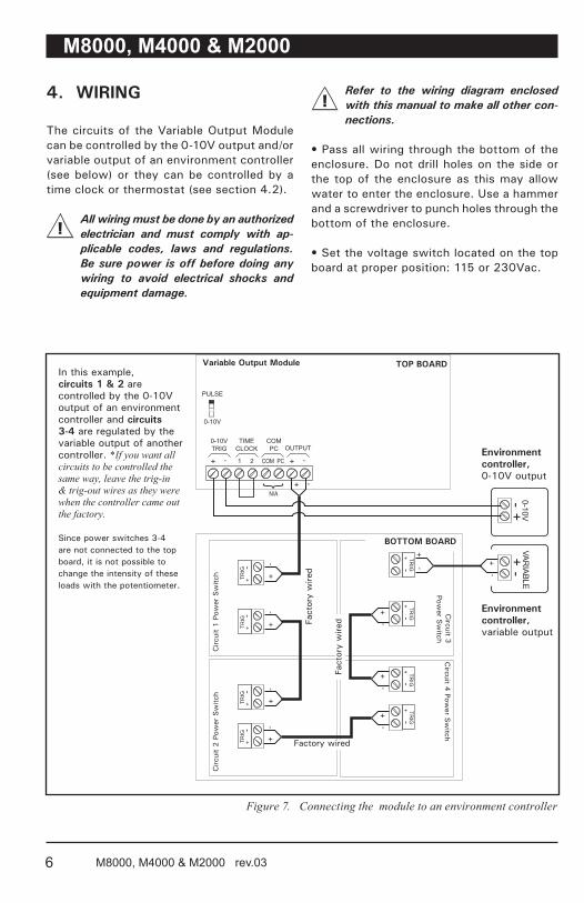
The circuits of the Variable Output Module can be controlled by the 0-10V output and/or variable output of an environment controller (see below) or they can be controlled by a time clock or thermostat (see section 4.2).
All wiring must be done by an authorized electrician and must comply with ap-plicable codes, laws and regulations. Be sure power is off before doing any wiring to avoid electrical shocks and equipment damage.
+ -
0-10VTRIG
TIMECLOCK
COMPC
1 2 COM PC
N/A
+ -OUTPUT
PULSE
0-10V
TRIG
+
-+
-
+ -+ -
+ -+ -
+
-+
-
+ -
+
-+
-
+ -
+ -
+ -
+ -
+
-+
-
0-10VVAR
IABLE+ -
- + +
-
TRIG
TRIG
TRIG
TRIG
TRIG
TRIG
TRIG
TOP BOARD
BOTTOM BOARD
Variable Output Module
Circ
uit
1 P
ower
Sw
itch
Fact
ory
wire
d
Fact
ory
wire
d
In this example, circuits 1 & 2 are controlled by the 0-10V output of an environment controller and circuits 3-4 are regulated by the variable output of another controller. *If you want all circuits to be controlled the same way, leave the trig-in & trig-out wires as they were when the controller came out the factory.
Since power switches 3-4 are not connected to the top board, it is not possible to change the intensity of these loads with the potentiometer.
Figure 7. Connecting the module to an environment controller
Environment controller, variable output
Environment controller,0-10V output
Refer to the wiring diagram enclosed with this manual to make all other con-nections.
• Pass all wiring through the bottom of the enclosure. Do not drill holes on the side or the top of the enclosure as this may allow water to enter the enclosure. Use a hammer and a screwdriver to punch holes through the bottom of the enclosure.
• Set the voltage switch located on the top board at proper position: 115 or 230Vac.
Factory wired
Circ
uit
2 P
ower
Sw
itch
Circuit 4
Power S
witch
Circuit 3
Power S
witch
7M8000, M4000 & M2000 rev.03
M8000, M4000 & M2000
4.1. Connect Module to Controller
Some circuits of a given module can be con-nected to the 0-10V output of an environ-ment controller while others are regulated by the variable output of another environment controller. Figure 7 gives an example of this.
If you prefer giving all circuits the same function, leave the trig-in & trig-out wires as they were when the controller came out the factory.
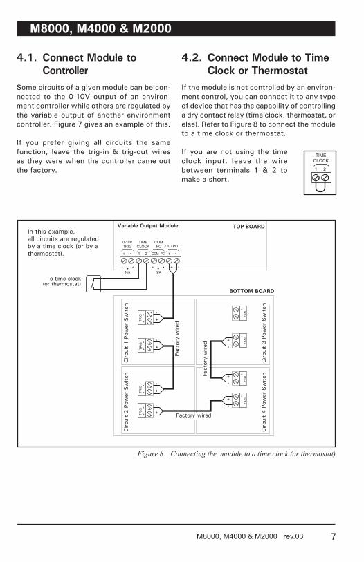
4.2. Connect Module to Time Clock or Thermostat
If the module is not controlled by an environ-ment control, you can connect it to any type of device that has the capability of controlling a dry contact relay (time clock, thermostat, or else). Refer to Figure 8 to connect the module to a time clock or thermostat.
If you are not using the time clock input, leave the wire between terminals 1 & 2 to make a short.
TIMECLOCK
1 2
+ -
0-10VTRIG
TIMECLOCK
COMPC
1 2 COM PC + -OUTPUT
+
-TR
IG+
-
+ -+ -
+ -+ -
+
-+
-
+ -
+
-
+ -
+ -
+ -
+
-+
-
+
-
N/A N/A
TRIG
TRIG
TRIG
TRIG
TRIG
TRIG
TRIG
To time clock(or thermostat)
In this example, all circuits are regulated by a time clock (or by a thermostat).
Figure 8. Connecting the module to a time clock (or thermostat)
BOTTOM BOARD
TOP BOARDVariable Output Module
Circ
uit
1 P
ower
Sw
itch
Fact
ory
wire
d
Fact
ory
wire
d
Factory wired
Circ
uit
2 P
ower
Sw
itch
Circ
uit
3 P
ower
Sw
itch
Circ
uit
4 P
ower
Sw
itch
8 M8000, M4000 & M2000 rev.03
M8000, M4000 & M2000
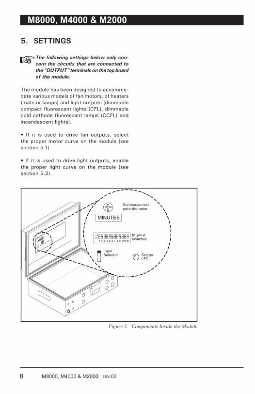
5. SETTINGS
The following settings below only con-cern the circuits that are connected to the “OUTPUT” terminals on the top board of the module.
The module has been designed to accommo-date various models of fan motors, of heaters (mats or lamps) and light outputs (dimmable compact fluorescent lights (CFL), dimmable cold cathode fluorescent lamps (CCFL) and incandescent lights).
• If it is used to drive fan outputs, select the proper motor curve on the module (see section 5.1).
• If it is used to drive light outputs, enable the proper light curve on the module (see section 5.2).
MINUTES
ON
OFF
1 2 3 4 5 6 7 8 9 10 11 12
Figure 3. Components Inside the Module
Sunrise/sunset potentiometer
Internalswitches
StatusLED
InputSelector
9M8000, M4000 & M2000 rev.03
M8000, M4000 & M2000
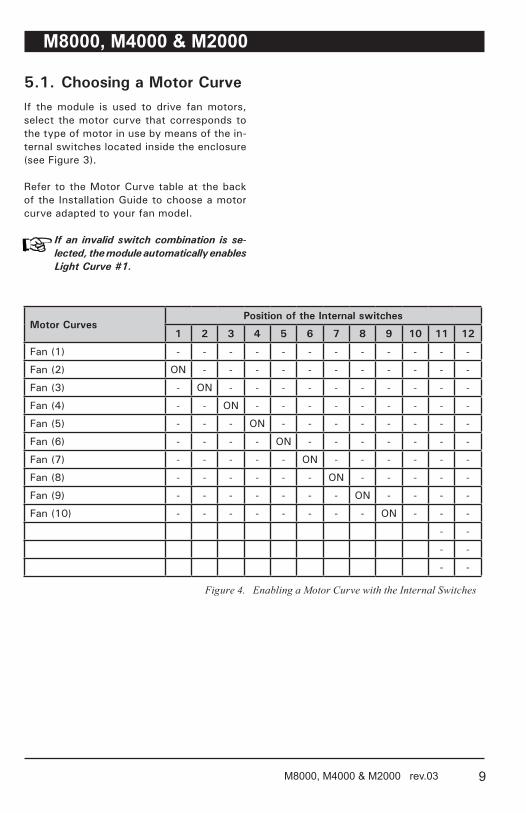
5.1. Choosing a Motor CurveIf the module is used to drive fan motors, select the motor curve that corresponds to the type of motor in use by means of the in-ternal switches located inside the enclosure (see Figure 3).
Refer to the Motor Curve table at the back of the Installation Guide to choose a motor curve adapted to your fan model.
If an invalid switch combination is se-lected, the module automatically enables Light Curve #1.
Motor CurvesPosition of the Internal switches
1 2 3 4 5 6 7 8 9 10 11 12
Fan (1) - - - - - - - - - - - -
Fan (2) ON - - - - - - - - - - -
Fan (3) - ON - - - - - - - - - -
Fan (4) - - ON - - - - - - - - -
Fan (5) - - - ON - - - - - - - -
Fan (6) - - - - ON - - - - - - -
Fan (7) - - - - - ON - - - - - -
Fan (8) - - - - - - ON - - - - -
Fan (9) - - - - - - - ON - - - -
Fan (10) - - - - - - - - ON - - -
- -
- -
- -
Figure 4. Enabling a Motor Curve with the Internal Switches
10 M8000, M4000 & M2000 rev.03
M8000, M4000 & M2000
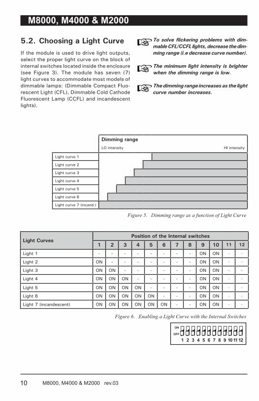
5.2. Choosing a Light CurveIf the module is used to drive light outputs, select the proper light curve on the block of internal switches located inside the enclosure (see Figure 3). The module has seven (7) light curves to accommodate most models of dimmable lamps: (Dimmable Compact Fluo-rescent Light (CFL), Dimmable Cold Cathode Fluorescent Lamp (CCFL) and incandescent lights).
To solve flickering problems with dim-mable CFL/CCFL lights, decrease the dim-ming range (i.e decrease curve number).
The minimum light intensity is brighter when the dimming range is low.
The dimming range increases as the light curve number increases.
Dimming rangeLO intensity HI intensity
Light curve 1
Light curve 2
Light curve 3
Light curve 4
Light curve 5
Light curve 6
Light curve 7 (incand.)
Figure 5. Dimming range as a function of Light Curve
Light CurvesPosition of the Internal switches
1 2 3 4 5 6 7 8 9 10 11 12
Light 1 - - - - - - - - ON ON - -
Light 2 ON - - - - - - - ON ON - -
Light 3 ON ON - - - - - - ON ON - -
Light 4 ON ON ON - - - - - ON ON - -
Light 5 ON ON ON ON - - - - ON ON - -
Light 6 ON ON ON ON ON - - - ON ON - -
Light 7 (incandescent) ON ON ON ON ON ON - - ON ON - -
Figure 6. Enabling a Light Curve with the Internal Switches
11M8000, M4000 & M2000 rev.03
M8000, M4000 & M2000
Settings
If the circuit activates CFL/CCFL lights, leave the lights ON for 24 hours after first installation before dimming.
1. Select light curve #7 on the block of internal switches inside the controller (see Figure 3) and refer to Figure 6 to set the switches properly.
When the light curve changes, the con-troller turns OFF the lights and turns them back ON using the new light curve.
2. Steps 3 and 4 only apply to CFL/CCFL lights (keep light curve #7 if the circuit is used to control incandescent lights or heating units).
3. Select the lowest light intensity with the potentiometer.
• If the lowest intensity is too bright, increase the light curve with the internal switches.
• If the lights are flickering, decrease the light curve with the internal switches.
4. Select another light curve if required and try to find one that provides a good minimum intensity and does not make the lights flicker.
If an invalid switch combination is se-lected, the module automatically enables Light Curve #1.
5.3. Setting Sunrise/SunsetIf the circuits are used to activate lights and they are controlled by a time clock, the module can simulate a sunrise (or sunset) before each activation (or deactivation) of the circuits.
Use the sunrise/sunset potentiometer behind the front panel (see Figure 3) to adjust the sunrise/sunset delay: Select the “0” posi-tion if you want to disable this function or select any other position to set the sunrise/sunset delay. This delay ranges from 0 to 60 minutes. Each time the relay switches, the module will gradually increase (sunrise) or decrease (sunset) the light intensity over this period of time.
All following conditions must be met for the sunrise/sunset to work:
•Theinternalswitcheshavealightingfunction (see Figure 6).
•Theoverrideswitchisatthe“AUTO” position.
•Thepotentiometeronthefrontcoveris not at the “AUTO” position.
12 M8000, M4000 & M2000 rev.03
M8000, M4000 & M2000
5.4. Selecting the Type of Input
Select 0-10V if the module is connected to the 0-10V output of an environment controller; otherwise, select PULSE.
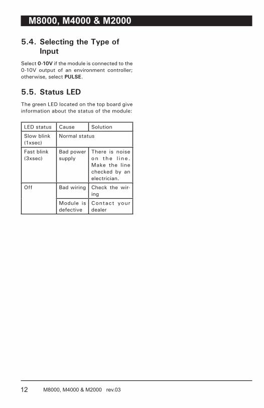
5.5. Status LEDThe green LED located on the top board give information about the status of the module:
LED status Cause Solution
Slow blink(1xsec)
Normal status
Fast blink(3xsec)
Bad power supply
There is noise on t he l i n e . Make the line checked by an electrician.
Off Bad wiring Check the wir-ing
Module is defective
Contact your dealer
13M8000, M4000 & M2000 rev.03
M8000, M4000 & M2000
6. DIMMABLE ENERGY-EFFICIENT LAMPS (CFL/CCFL)
6.1. About Dimmable CFL/CCFL
The module can control the intensity of two types of energy-efficient lamps:
1. Compact Fluorescent Light (CFL) — This refers to compact fluorescent light or energy saving light.
2. Cold Cathode Fluorescent Lamp (CCFL) — This refers to light sources that are based on gas discharge principles, where the cathode of the lamp is not independently heated.
• There are about 35 different electrical components in a typical dimmable CFL/CCFL which can cause the bulbs to react differently one another (some bulbs may extinguish early; other may flicker before they extinguish at their low end).
• Dimmable CFL/CCFL may cause interfer-ence with AM radios, cordless telephones and remote control devices.
• Dimable CFL should dim to 20% before they extinguish and CCFL should dim to 5-10%.
• The lifetime of CFL/CCFL are 8 times the lifetime of incandescent lamps. Many factors can affect their lifetime:
- Operating voltage;- Manufacturing defects;- Exposure to voltage spikes;- Mechanical shocks;- Frequency of On/Off cycles;- Lamp orientation;- Ambient operating temperature; - etc.
• The CFL/CCFL produce less light later in their lives than when they are new: a test made by the US Department of Energy of ‘Energy Star’ products in 2003–04 has dem-onstrated that one quarter of tested CFLs no longer met their rated output after 40% of their rated service life.
6.2. Recommended Models The brands and models of dimmable CFLs listed below have been tested and proven to work properly with the variable output module (other models can be used).
1. Overdrive, Sunlight and Greenlite 8W CCFL2. Retrolite 23W CFL
14 M8000, M4000 & M2000 rev.03
M8000, M4000 & M2000
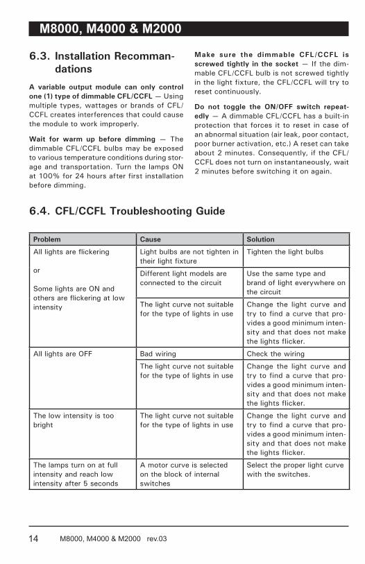
6.3. Installation Recomman-dations
A variable output module can only control one (1) type of dimmable CFL/CCFL — Using multiple types, wattages or brands of CFL/CCFL creates interferences that could cause the module to work improperly.
Wait for warm up before dimming — The dimmable CFL/CCFL bulbs may be exposed to various temperature conditions during stor-age and transportation. Turn the lamps ON at 100% for 24 hours after first installation before dimming.
Make sure the dimmable CFL/CCFL is screwed tightly in the socket — If the dim-mable CFL/CCFL bulb is not screwed tightly in the light fixture, the CFL/CCFL will try to reset continuously.
Do not toggle the ON/OFF switch repeat-edly — A dimmable CFL/CCFL has a built-in protection that forces it to reset in case of an abnormal situation (air leak, poor contact, poor burner activation, etc.) A reset can take about 2 minutes. Consequently, if the CFL/CCFL does not turn on instantaneously, wait 2 minutes before switching it on again.
6.4. CFL/CCFL Troubleshooting Guide
Problem Cause Solution
All lights are flickering
or
Some lights are ON and others are flickering at low intensity
Light bulbs are not tighten in their light fixture
Tighten the light bulbs
Different light models are connected to the circuit
Use the same type and brand of light everywhere on the circuit
The light curve not suitable for the type of lights in use
Change the light curve and try to find a curve that pro-vides a good minimum inten-sity and that does not make the lights flicker.
All lights are OFF Bad wiring Check the wiring
The light curve not suitable for the type of lights in use
Change the light curve and try to find a curve that pro-vides a good minimum inten-sity and that does not make the lights flicker.
The low intensity is too bright
The light curve not suitable for the type of lights in use
Change the light curve and try to find a curve that pro-vides a good minimum inten-sity and that does not make the lights flicker.
The lamps turn on at full intensity and reach low intensity after 5 seconds
A motor curve is selected on the block of internal switches


![Sun SPARC Enterprise™ …f.genais.free.fr/tutoSun/821-0338-10.pdfSubmit comments about this document by clicking the Feedback[+] link at: Sun SPARC Enterprise M3000/M4000/M5000/M8000/M9000](https://static.documents.pub/doc/80x56/5b31de797f8b9ae1108bf91b/sun-sparc-enterprise-f-comments-about-this-document-by-clicking-the-feedback.jpg)