TOOLS NEEDED • Metric tools • Floor jack • Jack stand (s) 4 • Wheel chocks • Drill and 3/8 bit BILL OF MATERIALS Part # Description Qty M20300 3” FT spacers 2 M20301 3” Rear spacers 2 BU76123 hardware 1 M20066 Ft bump ext 2 M20333 Rear bump ext 2 S11090 Sway Bar Drop brackets 2 KU01009 Ft shocks 2 KU01010 Rear shocks 2 P11183 Loctite 1 S20370 Rear track bar bracket 1 Other Jeep JK Products • KJ09145BK Hood Wranglers • KJ09144BK Tailgate Bumpstops • KJ71020 Upper dash panel • KJ71030 Lower switch panel • KU70034 Ft lower control arms • KU70033 Rear upper control arms • KU70037 Rear lower control arms • KU70091 poly flex tool • KU11005 Poly lube gun BOM FOR 3/4 KIT KJ09153 2007 to Current Jeep JK 3” lift with shocks www.Daystarweb.com Tech Support Contact Info [email protected]Phone: 623.907.0081 Fax: 623.907.0088 841 South 71 st Avenue Instruction Sheet P20372 2010 Daystar Products International Inc. Hells gate, Moab UT
Transcript
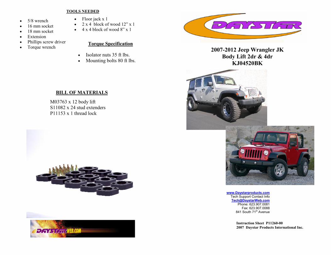
TOOLS NEEDED
• Metric tools • Floor jack • Jack stand (s) 4 • Wheel chocks • Drill and 3/8 bit
Instruction Sheet P20372 2010 Daystar Products International Inc.
Hells gate, Moab UT
Thank you for choosing Daystar Products
Daystar recommends a certified technician install this system . In addition to these instructions, professional knowledge of disassemble/reassembly proce-dures as well as post instructions checks must be known. Attempts to install this system without this knowledge and expertise may jeopardize the integrity and/or operating of the vehicle. Please read all the instructions before beginning the installation. Check the kit hardware against the parts list. Be sure you have all the needed parts and under-stand where they go. If anything is missing , do not proceed with the installa-tion, Call Daystar Products to obtain needed items.
Product Use Information
As a general rule, the taller a vehicle is the easier it will roll. We strongly recom-mend , because of rollover possibility, that seat belts and shoulder harness be worn at all times. Avoid situations where a side rollover may occur. Braking performance and capabilities are decreased when significantly large/heavier tires and wheels are used. Take this into consideration while driving, Also , speedometer recalibration is necessary when larger tires are installed. Do not add, alter, or fabricate any factory or after-market parts which increase vehicle height over the intended height of the Daystar Product purchased. Mixing component brands, lifts, and/or combining body lift with suspension lift voids all warranties. Daystar makes no claims regarding lifting devices and excludes any and all implied claims. We will not be responsible for any products that is al-tered.
Notice to Dealer and Vehicle Owner
Any vehicle equipped with any Daystar Product must have the “Warning to driver” decal installed on the sun visor or dash. The decal is to act a constant re-minder for whoever is operating the vehicle of its unique handling characteristics. INSTALLING DEALER— Its is your responsibility to install the warning decal and forward these instructions on too the vehicle owner for review and to be kept in the vehicle for service life. After installation occurs, a qualified alignment facility is required to align the vehicle to factory specs.
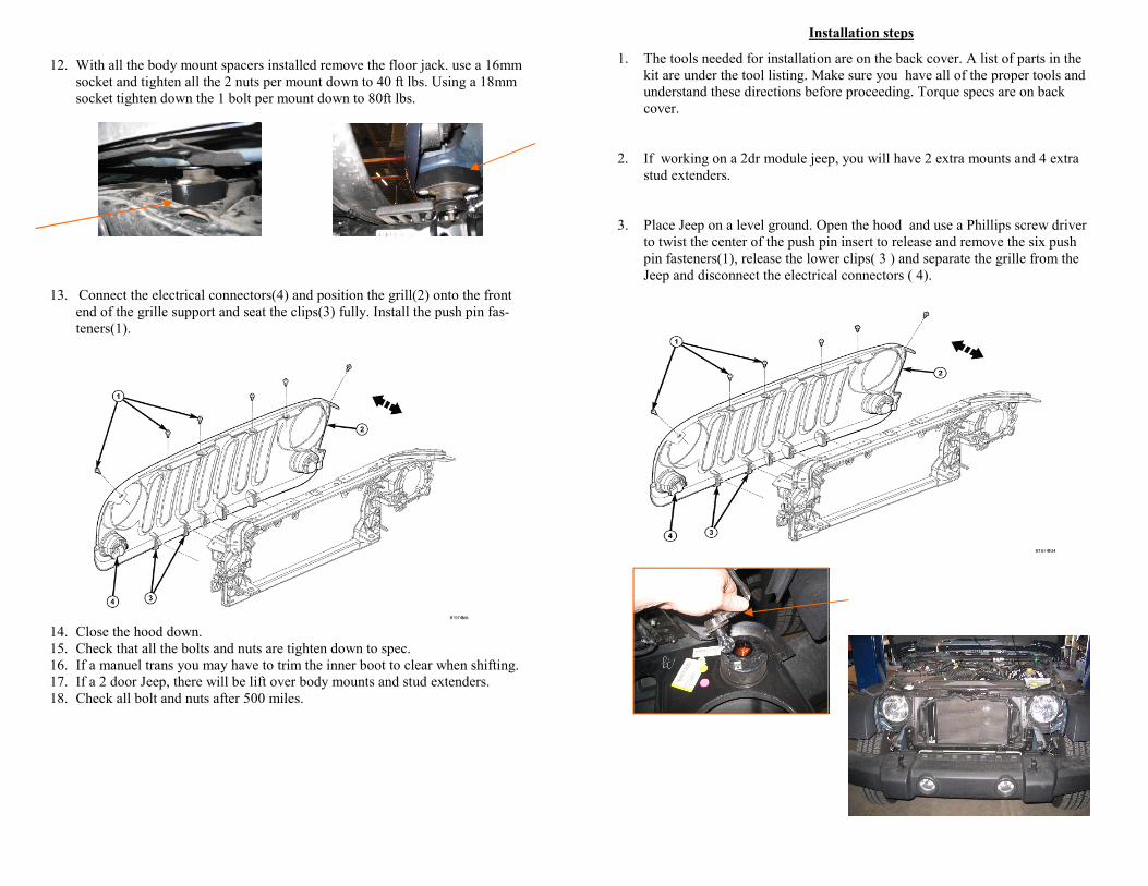
29. Install the rear wheels and lower the vehicle to the ground. 30. The vehicle should have a professional wheel alignment done at
this time. 31. Check all bolts and nuts after 500 miles and lug nuts.
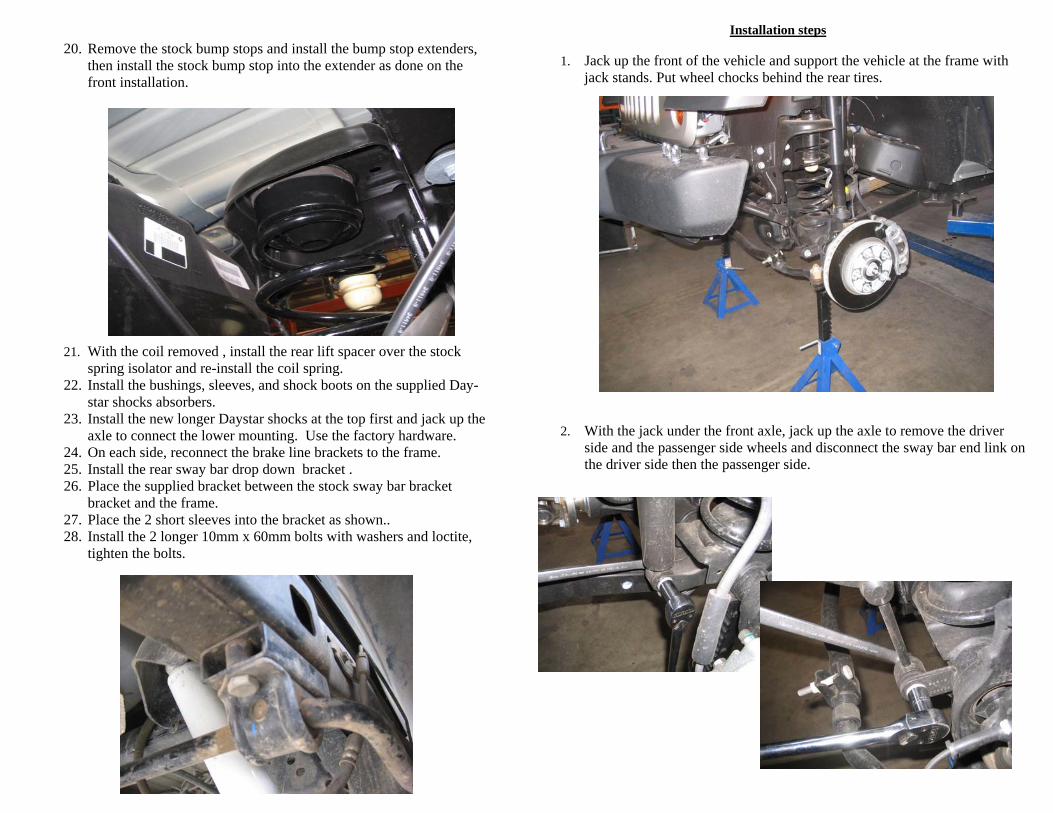
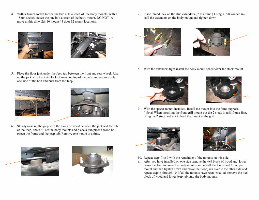
20. Remove the stock bump stops and install the bump stop extenders, then install the stock bump stop into the extender as done on the front installation.
21. With the coil removed , install the rear lift spacer over the stock spring isolator and re-install the coil spring.
22. Install the bushings, sleeves, and shock boots on the supplied Day-star shocks absorbers.
23. Install the new longer Daystar shocks at the top first and jack up the axle to connect the lower mounting. Use the factory hardware.
24. On each side, reconnect the brake line brackets to the frame. 25. Install the rear sway bar drop down bracket . 26. Place the supplied bracket between the stock sway bar bracket
bracket and the frame. 27. Place the 2 short sleeves into the bracket as shown.. 28. Install the 2 longer 10mm x 60mm bolts with washers and loctite,
tighten the bolts.
Installation steps
1. Jack up the front of the vehicle and support the vehicle at the frame with jack stands. Put wheel chocks behind the rear tires.
2. With the jack under the front axle, jack up the axle to remove the driver
side and the passenger side wheels and disconnect the sway bar end link on the driver side then the passenger side.
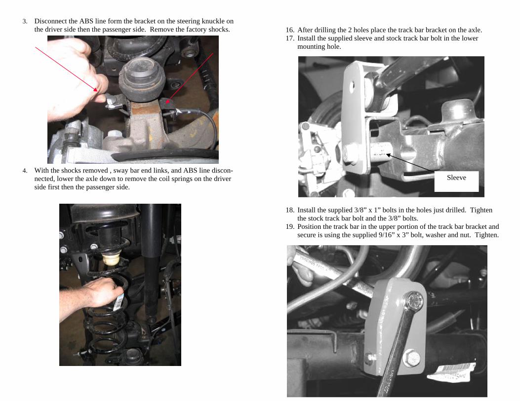
3. Disconnect the ABS line form the bracket on the steering knuckle on the driver side then the passenger side. Remove the factory shocks.
4. With the shocks removed , sway bar end links, and ABS line discon-
nected, lower the axle down to remove the coil springs on the driver side first then the passenger side.
16. After drilling the 2 holes place the track bar bracket on the axle. 17. Install the supplied sleeve and stock track bar bolt in the lower
mounting hole.
Sleeve
18. Install the supplied 3/8” x 1” bolts in the holes just drilled. Tighten the stock track bar bolt and the 3/8” bolts.
19. Position the track bar in the upper portion of the track bar bracket and secure is using the supplied 9/16” x 3” bolt, washer and nut. Tighten.
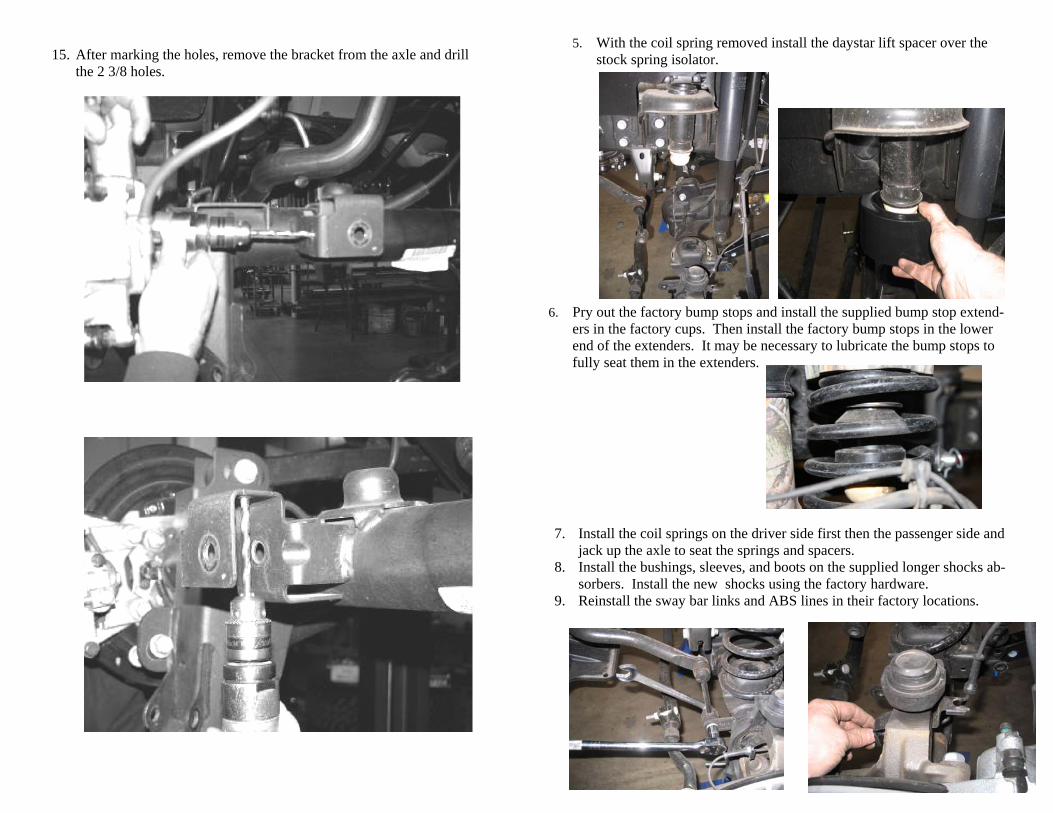
15. After marking the holes, remove the bracket from the axle and drill the 2 3/8 holes.
5. With the coil spring removed install the daystar lift spacer over the stock spring isolator.
7. Install the coil springs on the driver side first then the passenger side and jack up the axle to seat the springs and spacers.
8. Install the bushings, sleeves, and boots on the supplied longer shocks ab-sorbers. Install the new shocks using the factory hardware.
9. Reinstall the sway bar links and ABS lines in their factory locations.
6. Pry out the factory bump stops and install the supplied bump stop extend-ers in the factory cups. Then install the factory bump stops in the lower end of the extenders. It may be necessary to lubricate the bump stops to fully seat them in the extenders.
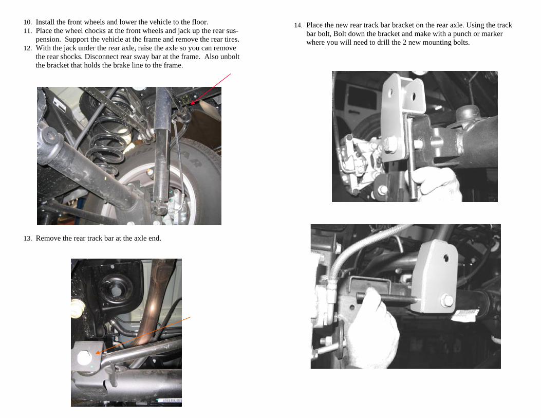
10. Install the front wheels and lower the vehicle to the floor. 11. Place the wheel chocks at the front wheels and jack up the rear sus-
pension. Support the vehicle at the frame and remove the rear tires. 12. With the jack under the rear axle, raise the axle so you can remove
the rear shocks. Disconnect rear sway bar at the frame. Also unbolt the bracket that holds the brake line to the frame.
13. Remove the rear track bar at the axle end.
14. Place the new rear track bar bracket on the rear axle. Using the track bar bolt, Bolt down the bracket and make with a punch or marker where you will need to drill the 2 new mounting bolts.