Douglas machine specification M305014 Kraft Maxwell House Specification Date: 8/2/05 Manufacturing No.: M647290 THIS INFO NOT TO Project Manager: LeRoy Gulbranson GO TO CUSTOMER Sales Engineer: Jim Brink Application Engineer: Steve Swanberg Electrical Designer: Steve Christenson Mechanical Designer: Kyle Harth Leadman: Service Advisor: Technical Writer: Administrative Assistant: Sandy Eldred INTERNAL SPECIFICATION SHEET SPECIAL INFORMATION SHEET. FOR DOUGLAS MACHINE INFORMATION ONLY (NOT TO BE INCLUDED WITH THE CUSTOMER'S COPY OF THE MACHINE SPEC). DOUGLAS EXPECTED SHIP DATE: 12/27/05 COMMENTS AND CONCEPTS OF WHAT WAS SOLD: This machine is similar to: PROJECT RATING: Was A Hard Project Meeting Held: ...................................................................................... Yes _ No X Hard Project Summary: Additional Information:
THIS INFO NOT TO Project Manager: LeRoy Gulbranson
GO TO CUSTOMER Sales Engineer: Jim Brink
Application Engineer: Steve Swanberg
Electrical Designer: Steve Christenson
Mechanical Designer: Kyle Harth
Leadman:
Service Advisor:
Technical Writer:
Administrative Assistant: Sandy Eldred
INTERNAL SPECIFICATION SHEET SPECIAL INFORMATION SHEET.
FOR DOUGLAS MACHINE INFORMATION ONLY (NOT TO BE INCLUDED WITH THE CUSTOMER'S COPY OF THE MACHINE SPEC). DOUGLAS EXPECTED SHIP DATE: 12/27/05 COMMENTS AND CONCEPTS OF WHAT WAS SOLD: This machine is similar to: PROJECT RATING: Was A Hard Project Meeting Held: ...................................................................................... Yes _ No X Hard Project Summary: Additional Information:
Douglas machine specifications
M305014 Douglas Machine Inc. 1
Customer: Kraft Maxwell House Machine Number: M305014
1.1. How is product received? Long dimension across conveyor
2. PACK PATTERNS AND SPEEDS:
Machine product speed (may differ from requested product speed).
Product Refer to Item 1
Pack Pattern
A X B X C
Direction of Travel
(A)
Vertical (B)
Across Machine
(C)
Film Tray Speed
Guaranteed Product Speed
3# plastic coffee containers in trays
1 x 1 x1 12.875” 6.5” 19.375” 1.5 – 1.75 mil
45 trays/min
4# plastic coffee containers in trays
1 x 1 x 1 12.875” 8.5” 19.375” 1.5 – 1.75 mil
45 trays/min
2.1. Film description: Non-printed polyethylene film approved by Douglas Machine.
2.1.1. Film width: Maximum 30”.
2.1.2. Film length: Maximum 45” extended film length requires increased machine elevation (per engineering determination).
Douglas machine specifications
M305014 Douglas Machine Inc. 2
3. SIZE RANGE:
3.1. Infeed section (outside product dimension):
Direction of Travel Vertical Dimension Across Conveyor
Minimum: 8” 5” 12”
Maximum: 13.50” 10” 22”
3.1.1. This single roll system has the design base of 45 cycles per minute with capability to cut and wrap film thickness from 1.5 to 1.75 mil. The product size, film thickness and tunnel length will allow operation of this machine at package/speed capabilities in item 2.
4. SHRINK-WRAP TOLERANCES:
4.1. Film cutoff: + 1/8” of total length.
4.2. Film placement in Direction Of Travel: + 1/4” placement of leading edge of film.
4.3. Film overlap: 1-1/2” minimum.
4.4. Film overlap alignment: + 3/8” as measured from the outermost edge of the film wrap.
5. MACHINE ORIENTATION:
5.1. Sequence of operation: Product is received from upstream equipment in a single lane with the long dimension across the machine. The product metering system requires surge to operate. Once surge has built up, the product is metered by a servo braking belt mechanism onto the wrapper conveyor, in time with the wrapping mechanism. Film is automatically cut to the correct length and positioned under the product. The wrapping mechanism is a rotating wand that travels around the product providing overlapped film under the tray. Each package continues through the shrink tunnel where heat is applied to all sides of the package, including the bottom. The overlap is sealed by hot air passing through the open web conveyor. Controlled airflow within the tunnel ensures a uniform shrink to the film.
5.2. Floor plan number: #FP-050491 B
5.3. Infeed height: Standard 40-3/4” with 3” frame-to-floor clearance. Adjustability: minimum 39” to 42-1/4” 40” elevation to match CMTP
5.4. Discharge height: Standard 40-3/4” with 3” frame-to-floor clearance. Adjustability: minimum 39” to 42-1/4” 40” elevation to match CMTP
5.5. Leg style: Threaded rod.
Douglas machine specifications
M305014 Douglas Machine Inc. 3
6. SHIPPING SIZE REQUIREMENTS: Maximum size 95” wide by 100” high x lengths
determined by machine design.
7. EQUIPMENT SPECIFICATIONS: This machine is designed with high quality components for standardization. Any changes other than those listed in options are not available on this model.
8. OPERATING CONDITIONS:
8.1. Ambient temperature: 50°- 100° F.
8.2. Humidity: Recommended 75% maximum.
9. UTILITY REQUIREMENT:
9.1. Plant voltage: 480V-3ph-60Hz.
9.2. Air requirements: 90 psi, clean, dry.
10. MECHANICAL FEATURES:
10.1. Shrink tunnel: The 8-foot shrink tunnel provides control of airflow, temperature, velocity, and tunnel conveyor speed along with continuous re-circulation of air for optimum efficiency. The tunnel belt speed is controlled by an Allen-Bradley variable frequency drive. It features an automatic shutdown to prevent heater failure if the fan blower malfunctions. Tunnel has a powered adjust product height change.
10.2. Film feed cutting: An Allen-Bradley servo motor drives the film feed/cutting system. Film is removed from the roll by servo driven nip rollers.
10.3. Film roll spindle: Up to 20” diameter rolls of film on 3” diameter cores can be used. It has a single spindle for film feed and does not have a splice bar. Splicing is accomplished by taping the end of the roll to the beginning of the new roll and cycling the machine until the splice can be removed. Optional two roll side film stand with splice bar was selected.
10.4. Machine frame: Welded tubular steel with leveling legs. Optional continuous weld was selected.
10.5. Fabricated parts: Skip weld. Optional continuous weld was selected.
10.6.4.2. Doors and panels: Clear ¼” polycarbonate in aluminum frame.
10.6.4.3. Safety: Guard doors with handles and interlocks are installed where machine operators may need access to the machine. All other guard doors will require a tool to open and/or remove.
10.7. Bearings: The majority of bearings are non-relube minimum maintenance bearings. For bearings and bushings requiring lubrication, the lines are stainless steel and flexible plastic. Linear bearings and rod ends will have their standard fittings.
10.8. Lubrication system:
10.8.1. Grease bank system: Grease banks, where required, are mounted in groups on the machine frame for convenient servicing. Fittings have color disc to indicate frequency.
10.8.2. Type of grease in system: Non-food grade.
10.8.3. Type of oil in system: Non-food grade. Food grade oil not available in sealed gear heads, phasing gear boxes, indexers, and servo gear boxes. Synthetic oil is used in servo gear boxes.
10.9. Hardened sprockets: All roller chain sprockets, other than sprockets used for adjustments.
10.10. Adjustment indicators: Scales in inches and digital indicators.
10.11. Additional components: Aurora steel insert rod ends
Additional items to be included Servo driven wand with changeable cam tracks New tunnel design Number all guards with large numbers Bank solenoid valves on outside of frame
11.12.3. Emergency stops: Allen-Bradley 800T (2 standard, 1 with HMI and 1 remote).
11.13. Heater control: PLC PanelView display and control.
11.14. Downstream surge control: Dwells machine if trays are detected at discharge.
11.15. Temperature alarm: High/low detection.
11.16. Low film alarm: End of roll detection.
11.17. Overload detection: Stops the machine when actuated and displays the location on the HMI.
11.18. Modem: Online communications with the machine program (requires customer to supply phone line).
11.19. Additional components: Allen-Bradley motor control
Allen-Bradley pushbuttons
Allen-Bradley photo controls
Bussman fuses and fuse blocks
Hoffman electrical enclosures
Turck proximity switches
Wago cage clamp terminals
Idec control relays
Hevi-Duty transformers
11.20. Electrical miscellaneous: Options selected ControlNet module Flange mounted disconnect with circuit breaker 3 color stack light Startup delay with warning horn
Douglas machine specifications
M305014 Douglas Machine Inc. 6
Separate guard door annunciation Enclosure light Sola isolation transformer
Additional items to be included Light over the cutter assembly Rexroth Ceramic solenoid valves Broken film detection on vacuum table
12. CLEANING: Douglas Machine Shrink-Wrap Systems are not designed to be operated in washdown environments. Under no circumstances should water, or any other liquid, be directed at any part of the wrapper or tunnel. Product spillage should be removed by wiping.
12.1. Machine structure: Wipe off machine components using a dry rag. Use dry compressed air, maximum of 40 PSI, to remove accumulations such as corrugated dust. Do not direct air pressure to sensitive areas of the machine such as the inside of electrical cabinets, electrical devices, bearing seals, hot melt applicator, etc.
12.2. Lexan upper guard panels: Clean with soft, damp cloth. Abrasive pads should not be used.
12.3. Clarification: Options such as Nema 4X wiring, stainless steel fasteners, chain oilers, etc., are intended for aid in resistance to corrosion. However, commercially supplied components such as bearings, gearboxes, reducers, valves, torque limiters, clutches, hot melt applicator, etc., are typically installed with their manufacturer’s standard supplied finish (normally painted), and are not necessarily waterproof or corrosion resistant. Detergents, high-pressure water, and/or caustic solutions (alkaline/acidic), applied to this machine, may cause component malfunction and/or corrosion.
13. LANGUAGE:
13.1. Manuals: English.
13.2. Warning signs: English.
13.3. Human Machine Interface (HMI): English.
14. SPARE PARTS: Not included. Offered as an option.
15. MACHINE EFFICIENCY: 98% Consult Douglas Machine Inc. for specifics.
16. FAT AT DOUGLAS MACHINE: Acceptance testing of the machine with customer-supplied materials will consist of 2-5 minute runs per product size and pack pattern.
17. FAT AT CUSTOMER PLANT: Acceptance testing of the machine will consist of 2 consecutive 8-hour runs. Douglas Machine personnel will be available to support this test at our current technical support rates. See attached rate sheet. Consult Douglas Machine Inc. for specifics.
Douglas options selected
M305014 Douglas Machine Inc. 7
Elevation change: Standard: 40-3/4” with 3” frame-to-floor clearance. Additional legs for 12” floor clearance .........................
ControlNet module: ControlNet module only (no programming) .................
Flange mounted disconnect with circuit breaker: Flange mounted disconnect with circuit breaker versus standard rotary style disconnect ......................
Galvanized conduit: Galvanized conduit versus standard rigid aluminum ...
Warning horn: Delayed start with horn ................................................
Separate guard door annunciation: Separate PLC inputs and HMI messages for each guard door interlock .....................................................
Enclosure light: Enclosure light for main electrical enclosure ...............
Continuous weld: Continuous weld versus some skip weld .....................
Cooling fans: One fan is mounted to the top of the tunnel and blows ambient air onto the bundle on the customer’s take away conveyor and the a second fan is mounted below the conveyor ......................................................
Manual tunnel advance: Manual conveyor advance to allow removal of the product from the heat tunnel if a power failure occurs
Film cart: For transporting and handling of film rolls ...................
Two roll side film stand: Up to 20” diameter film rolls mount in a two roll vertical rack. This allows a roll of film to be preloaded onto one arbor in preparation for splicing while running on the opposite arbor. This stand is located outside the frame with the film rolls positioned parallel to the direction of travel. Included with this option is a splice bar, which allows a new film roll to be manually spliced to the end of the old roll. The splice bar will provide a heat seal splice eliminating the need for taping ...........................................................................
Isolation transformer: Sola brand isolation transformer for PLC protection ...
Kraft Foods – Equipment Package Specification for LD, Traypacker, and Shrink Tunnel System
Kraft Foods – Basic Mechanical Requirements
Kraft Foods – Electrical Requirements for Purchased Equipment (Division 16.021)
List all exceptions and clarifications to customer specifications.
Attachment A Kraft Foods – Equipment Package Specification for LD, Traypacker, and Shrink Tunnel System
Attachment B Kraft Foods – Basic Mechanical Requirements
Attachment C Kraft Foods – Electrical Requirements for Purchased Equipment (Division 16.021)
Attachment A Kraft Foods – Equipment Package Specification for LD, Traypacker, and Shrink Prepared by Washington Group International Rev.0 June 2, 2005
Douglas Machine Exceptions and Clarifications
M305014 Douglas Machine Inc. 9
A. General
1.g. Training packages are optioned. Formalized training per attached training quote will be developed at no charge to Kraft. Kraft must purchase delivery of training to receive the package.
1.h. Installation, start-up, and commissioning is an option.
2. REFERENCE CODES: Douglas Machine manufactured equipment will comply with applicable standards of the National Fire Protection Association’s NFPA 70 (National Electrical Code) and NFPA 79 (Electrical Standards for Industrial Machinery) as well as Douglas Machine’s Product Safety Standards and Electrical Engineering Standards.
OSHA STANDARDS: Douglas Machine is designed to comply with OSHA Standards to the best of our abilities and interpretation. Full compliance with OSHA Standards involves the use of the equipment at the customer’s plant and therefore is not fully controllable by the manufacturer. We cannot, therefore, certify that our equipment conforms in all respects, with OSHA Standards. After the machine is completed and being test run with your product, we would like your people here for instruction, training, and acceptance of the machine. Any specific requirements of OSHA that are of concern to you can be itemized and we will quote the additional work necessary to make our equipment comply.
B. Products
1.h. Machine orientation needs to be determined.
2.e.3) Missing film detection is provided, but broken film is not.
2.e.4) Film tracking is depended on the roll position.
2.e.6) Manual handwheel for tunnel is an option.
2.e.7) Stack light and warning horn are options.
2.e.9) Stack light and warning horn are options.
2.e.10) Static eliminators are provided for the machine, not for each roll unwind station.
2.e.11) Film rolls are not powered. Nip rollers on the cutter assembly pull film off the roll.
2.f.1) Shrink discharge conveyor is an option.
2.f.2) Two cooling fans is an option.
3.a.2) UL labeled electrical enclosures is an option.
3.a.3) The optional separate glue disconnect requires a separate 480v,3Ph,60Hz power drop.
3.b.1) Separate glue disconnect is an option.
3.b.3) Magazine drive motors are 90 VDC.
3.c.3) Two (2) E-stops are standard on each machine (lane divider, tray packer, shrink wrapper). Additional E-stops are optioned.
3.c.4) Low magazine detection is an option.
3.c.8) Rigid aluminum conduit is standard. Rigid galvanized conduit is an option.
Attachment A Kraft Foods – Equipment Package Specification for LD, Traypacker, and Shrink Prepared by Washington Group International Rev.0 June 2, 2005
Douglas Machine Exceptions and Clarifications
M305014 Douglas Machine Inc. 10
3.c.9) Open flap detection is an option.
4. Kraft’s factory acceptance test is an option.
5.c. Douglas standard 98% efficiency is included.
5.f.1) Douglas will have Service Technicians available for commissioning per our enclosed rate schedule.
C. Execution
4. Spare parts list will be finalized after machine shipment. Preliminary spare parts list can be provided before machine shipment.
Attachment B Kraft Foods – Basic Mechanical Requirements March 23, 2001 Douglas Machine Exceptions and Clarifications
M305014 Douglas Machine Inc. 11
B. Standard Design Requirements
1.d.1) Prelubed minimum maintenance bearings are used.
1.e.1) Not all shafts will have flats for set screws.
1.g. Continuous weld is an option.
1.o. Extended legs for a 12” floor clearance is an option.
2.a Ringfedders are clear coated.
Attachment C Kraft Foods – Electrical Requirements for Purchased Equipment (Division 16.021) Revision 2.3, Dated June, 2002 Douglas Machine Exceptions and Clarifications
M305014 Douglas Machine Inc. 12
Section 1 – Design Strategy & Responsibility
1.01 Kraft Foods Integration Guidelines (16.006) will not be followed.
1.02 A. The main electrical enclosures will mounted on the machines.
1.02 C. Approval drawings typically add calendar time to a project. Douglas needs the drawings back within one week to keep the effect on the delivery date minimal. Deviations made after the approval will not go through the approval process.
1.02 D. Douglas will create one sequence of operation during the design process. This document will be updated to reflect the as built machine.
1.02 G. Douglas does not plan on using any sub-vendors. Components like coders and glue tanks will have their own documentation package.
1.02 K. Development software will not be provided. Douglas recommends that Kraft purchase the development software from Rockwell.
1.02 L Training packages are optioned. Formalized training per attached training quote will be developed at no charge to Kraft. Kraft must purchase delivery of training to receive the package.
1.02 M. Test specifications will not be developed.
1.02 O Start-up and Commissioning is optioned.
1.02 P. UL labeled electrical enclosure is an option. The machine will not be UL approved.
1.03 A. A testing plan will not be developed.
1.04 Douglas standard communications to the HMI is Ethernet. DeviceNet is used for communications to VFDs and Point I/O modules. A ControlNet module for line communications is an option.
1.05 A. Any plant Electrical Standard received will need to go through this same process to document exceptions and clarifications.
1.05 B. Motor control will be mounted in the main electrical enclosure.
1.06 C. Section X if received will need to go through this same process to document exceptions and clarifications.
1.06 D. Additional hardware and software to connect to Kraft Foods’ MES system will not be provided.
1.08 Additional hardware and software to connect to Kraft Foods’ MES system will not be provided.
Section 2 – Vendor Drawings / Documentation
2.01 A. Douglas standard electrical drawings are provided on B size (11 x 17) sheets but D size (22 x 34) can be provided if required.
2.01 B. Douglas uses CADRA software to create drawings. Drawings can be converted to AutoCad format at the completion of the project.
2.01 C. Douglas standard formats and symbols will be used to create the drawings.
2.01 D. All manuals are created with Frame Maker Software and converted to PDF format.
2.01 F. Bill of Material lists are not included on the drawings. BOMs can be provided as a separate document.
Attachment C Kraft Foods – Electrical Requirements for Purchased Equipment (Division 16.021) Revision 2.3, Dated June, 2002 Douglas Machine Exceptions and Clarifications
M305014 Douglas Machine Inc. 13
2.02 Douglas standard drawing numbers, border, and title block will be used. At the completion of the project Douglas could copy the drawing onto Kraft provided border and title block templates.
2.02 D. Approval drawings typically add calendar time to a project. Douglas needs the drawings back within one week to keep the effect on the delivery date minimal
2.03 A. Douglas standard electrical drawings will be provided. The following drawings are not included: Conduit and Cable Diagrams Fabrication Shop Drawings Pneumatic Conduit Diagrams
2.04 Douglas will provide the require information for Kraft to create the project file folder.
2.05 A. Development software will not be provided. Douglas recommends that Kraft purchase the development software from Rockwell.
2.05 C. Douglas standard program naming convention will be used.
2.05 G. All manuals are created with Frame Maker Software and converted to PDF format.
2.06 Douglas standard drawing title block will be used.
Section 3 – Electrical Power Distribution
3.01 B. Douglas standard disconnect is a through the door rotary style. Flange mounted disconnect with internally mounted circuit breaker is an option.
3.01 E. Circuit breaker panel boards are not provided.
3.01 F. The electrical panels will not be certified in writing from Electrical Contractor. If the option is chosen, the electrical enclosures can be UL labeled.
Section 4 – Process, Controls, & Instrumentation
4.01 D. NEMA 12 is standard. NEMA 4X is not being option for this application.
4.02 A. Kraft Foods North American Sanitary Design Standards will not be followed.
4.02 B. Most of the enclosures provided by Douglas Machine have continuous hinges. NEMA 4X is not being option for this application.
4.02 D. Air conditioner for the main electrical enclosure is an option.
4.02 E. Enclosure light is an option.
4.02 F. Ethernet communication is provided. ControlNet communications is an option.
4.02 I. If special cleaning agents will be used, Kraft should get approval from Douglas.
4.02 N. Since enclosures are bolted to the bottom frame member, the machine height will affect the clearance between the bottom of the enclosure and the floor.
4.02 N. Flange mounted main disconnect with circuit breaker is an option.
4.02 T. If two or three door enclosures are used, control will be on one side and power will be on the other side.
4.02 U. The NEMA rating of the enclosure must be conserved. This requires special enclosure mounting.
4.03 B. Some internal cabinet wiring for motors and power wiring may be MTW.
Attachment C Kraft Foods – Electrical Requirements for Purchased Equipment (Division 16.021) Revision 2.3, Dated June, 2002 Douglas Machine Exceptions and Clarifications
M305014 Douglas Machine Inc. 14
4.03 E. All wire numbers shall reflect the appropriate column and row and or line number. Wire markers will be Douglas standard computer printed snug fit plastic sleeves.
4.03 I. Some cords will be longer than three feet.
4.03 J. Separate guard door annunciation, stack lights, and audible alarm are options.
4.03 L. PLC outputs with built in overload protection will be used. Additional fuses required to individually fuse the input modules is an option.
4.03 M. Separate conduit runs is an option.
4.03 P. Sola isolation transformer is an option.
4.03 Q. Control voltage will be 24 VDC.
4.04 A. Rigid aluminum conduit will be used. Rigid galvanized conduit is an option.
4.04 B. Some wireway will be used. Since this is a NEMA 12 application, the wireways will not be rotated 45°.
4.04 F. Some cables used for servomotors and sensors will not be in a raceway.
4.06 G. Neutral wires will be identified as shown on the electrical drawings.
4.06 H. Power wires will be identified as shown on the electrical drawings.
4.07 A. Sola isolation transformer is an option.
4.08 B. Type J fuses will be used for all motor protection fuses.
4.08 E. PLC outputs with built in overload protection will be used. Additional fuses required to individually fuse the input modules will be provided.
4.09 E. Allen-Bradley Bulletin 140 motor protectors are used for motor overload protection.
4.10 B. A line reactor for VFDs will not be provided.
4.10 G. All VFDs will have DeviceNet communications.
4.11 C. Douglas tries to reduce the number of different servomotors as much as possible.
4.11 G. Servo motors will not have a stainless steel housing and motor shaft.
4.11 J. Additional connectors may be used if a portion of the feedback cable is required to flex. The flexible portion is a separate cable that can be replaced.
4.13 B. Terminal blocks will be Wago Cage Clamp style.
4.14 A. Magazine drive motors are 90 VDC.
4.14 D. Separate motor disconnects are an option. Motor disconnects will not be provided for the servomotors.
4.14 E. Reliance Super Clean Plus motors will not be provided.
4.14 F. Separate motor disconnects are an option. Motor disconnects will not be provided for the servomotors.
4.15 B. Some cables for sensors may be longer than 6 feet.
Attachment C Kraft Foods – Electrical Requirements for Purchased Equipment (Division 16.021) Revision 2.3, Dated June, 2002 Douglas Machine Exceptions and Clarifications
M305014 Douglas Machine Inc. 15
4.15 D. Quick disconnect cords will be provided.
4.17 A. Dodge nylon coated E-Z Kleen Tigear speed reducers and standard Dodge Tigear gearboxes.
4.18 Pneumatic components will not be mounted in cabinets, but will be mounted to the machine frame were they are required.
Section 5 – Electrical Design Standards for Safety
Douglas standard safety circuits will be provided. Allen-Bradley 440K tongue or key actuated interlock switches are provided on all guards that can be opened. Two emergency stop switches are provided as standard and additional e-stops are an option. Guard door interlocks and emergency stops are wired to an Allen-Bradley 440R safety relay. Separate motor disconnects are an option but they will not be provided for servomotors. Category 3 requirements will be met. Section 6 – Operating & Maint. Training Manuals
As part of our National Account Purchase Agreement, Douglas does provide training development for new machines based on quote for training attached. Kraft is responsible for ordering the training delivery to achieve this cost savings.
Section 7 – PLC and HMI Requirements
7.01 Development software will not be provided. Douglas recommends that Kraft purchase the development software from Rockwell.
7.02 I. Un-interruptible power supply (UPS) will not be provided.
7.03 D. Allen-Bradley PanelView Plus 1000 color touch screen will be used.
7.04 Douglas standard programming methods will be used. Servo driven machines utilize sequential function chart (SFC) programming language as well as ladder. Kraft can review a typical program with Douglas if they would like to know more about the programming methods that Douglas uses.
7.05 RSViewStudio “ME” (Machine Edition) will be used for the PanelView Plus HMI.
Section 8 – Network Communications
As a standard Douglas uses DeviceNet communications to VFDs and point I/O. EtherNet communications is used for the HMI. A ControlNet module is an option for peer-to-peer communications.
Section 9 – Standard Electrical Components
AC Inverters A-B PowerFlex 40 VFDs will be used.
Servo Systems A-B 1756-L61 processor will be used with 1756-M08SE or 1756-M16SE sercos modules. A-B Kinetics servo drives and MPL motors will be used.
PLC Distributed I/O A-B Point I/O on DeviceNet communications will be used.
Operator Interfaces PanelView 1000 Plus
Safety Relay A-B Minotaur MSR16R/T #440R-N23059
Interlock Switch A-B #440K-T11146
Control Relays Idec 24 VDC
DC Drive Control Dart
Attachment C Kraft Foods – Electrical Requirements for Purchased Equipment (Division 16.021) Revision 2.3, Dated June, 2002 Douglas Machine Exceptions and Clarifications
M305014 Douglas Machine Inc. 16
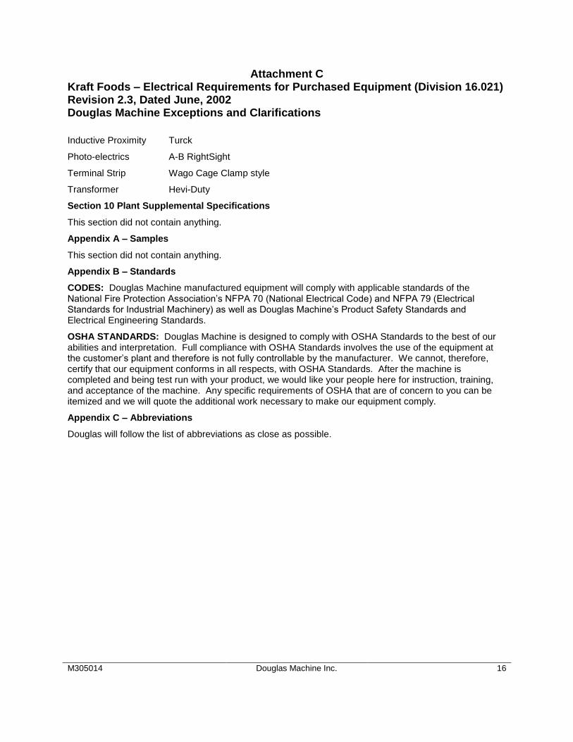
Inductive Proximity Turck
Photo-electrics A-B RightSight
Terminal Strip Wago Cage Clamp style
Transformer Hevi-Duty
Section 10 Plant Supplemental Specifications
This section did not contain anything.
Appendix A – Samples
This section did not contain anything.
Appendix B – Standards
CODES: Douglas Machine manufactured equipment will comply with applicable standards of the National Fire Protection Association’s NFPA 70 (National Electrical Code) and NFPA 79 (Electrical Standards for Industrial Machinery) as well as Douglas Machine’s Product Safety Standards and Electrical Engineering Standards.
OSHA STANDARDS: Douglas Machine is designed to comply with OSHA Standards to the best of our abilities and interpretation. Full compliance with OSHA Standards involves the use of the equipment at the customer’s plant and therefore is not fully controllable by the manufacturer. We cannot, therefore, certify that our equipment conforms in all respects, with OSHA Standards. After the machine is completed and being test run with your product, we would like your people here for instruction, training, and acceptance of the machine. Any specific requirements of OSHA that are of concern to you can be itemized and we will quote the additional work necessary to make our equipment comply.
Appendix C – Abbreviations
Douglas will follow the list of abbreviations as close as possible.
Douglas documentation & training
M305014 Douglas Machine Inc. 17
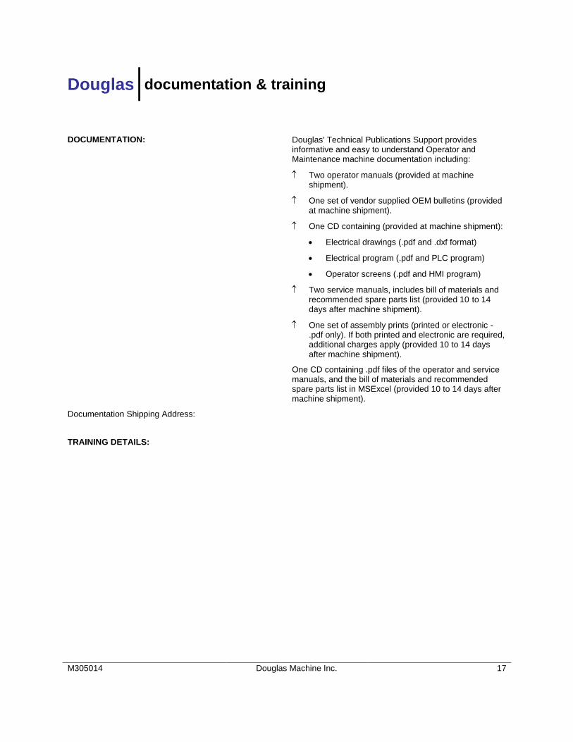
DOCUMENTATION: Douglas' Technical Publications Support provides informative and easy to understand Operator and Maintenance machine documentation including:
Two operator manuals (provided at machine shipment).
One set of vendor supplied OEM bulletins (provided at machine shipment).
One CD containing (provided at machine shipment):
Electrical drawings (.pdf and .dxf format)
Electrical program (.pdf and PLC program)
Operator screens (.pdf and HMI program)
Two service manuals, includes bill of materials and recommended spare parts list (provided 10 to 14 days after machine shipment).
One set of assembly prints (printed or electronic - .pdf only). If both printed and electronic are required, additional charges apply (provided 10 to 14 days after machine shipment).
One CD containing .pdf files of the operator and service manuals, and the bill of materials and recommended spare parts list in MSExcel (provided 10 to 14 days after machine shipment).
Documentation Shipping Address:
TRAINING DETAILS:
Douglas installation & spare parts
M305014 Douglas Machine Inc. 18
INSTALLATION DETAILS:
SPARE PARTS DETAILS:
Douglas limited warranty statement
M305014 Douglas Machine Inc. 19
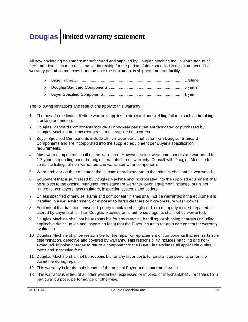
All new packaging equipment manufactured and supplied by Douglas Machine Inc. is warranted to be
free from defects in materials and workmanship for the period of time specified in this statement. The
warranty period commences from the date the equipment is shipped from our facility.
Base Frame .................................................................................................. Lifetime
Douglas Standard Components ................................................................... 3 years
Buyer Specified Components ....................................................................... 1 year
The following limitations and restrictions apply to this warranty:
1. The base frame limited lifetime warranty applies to structural and welding failures such as breaking,
cracking or bending.
2. Douglas Standard Components include all non-wear parts that are fabricated or purchased by
Douglas Machine and incorporated into the supplied equipment.
3. Buyer Specified Components include all non-wear parts that differ from Douglas’ Standard
Components and are incorporated into the supplied equipment per Buyer’s specification
requirements.
4. Most wear components shall not be warranted. However, select wear components are warranted for
1-2 years depending upon the original manufacturer’s warranty. Consult with Douglas Machine for
complete listings of non-warranted and warranted wear components.
5. Wear and tear on the equipment that is considered standard in the industry shall not be warranted.
6. Equipment that is purchased by Douglas Machine and incorporated into the supplied equipment shall
be subject to the original manufacturer’s standard warranty. Such equipment includes, but is not
limited to, conveyors, accumulators, inspection systems and coders.
7. Unless specified otherwise, frame and component finishes shall not be warranted if the equipment is
installed in a wet environment, or exposed to harsh cleaners or high-pressure wash downs.
8. Equipment that has been misused, poorly maintained, neglected, or improperly moved, repaired or
altered by anyone other than Douglas Machine or its authorized agents shall not be warranted.
9. Douglas Machine shall not be responsible for any removal, handling, or shipping charges (including
applicable duties, taxes and inspection fees) that the Buyer incurs to return a component for warranty
evaluation.
10. Douglas Machine shall be responsible for the repair or replacement of components that are, in its sole
determination, defective and covered by warranty. This responsibility includes handling and non-
expedited shipping charges to return a component to the Buyer, but excludes all applicable duties,
taxes and inspection fees.
11. Douglas Machine shall not be responsible for any labor costs to reinstall components or for line
downtime during repair.
12. This warranty is for the sole benefit of the original Buyer and is not transferable.
13. This warranty is in lieu of all other warranties, expressed or implied, or merchantability, or fitness for a
particular purpose, performance or otherwise.
Douglas component warranty list
M305014 Douglas Machine Inc. 20
Douglas standard components include all non-wear parts that are fabricated or purchased by Douglas Machine and incorporated into the supplied equipment. Most wear components shall not be warranted. However, select wear components are warranted for 1-2 years depending upon the original manufacturer’s warranty. See list below for a description and warranty period of Douglas standard components and wear and non-wear components. 3-YEAR WARRANTY 1-YEAR WARRANTY
Brake Pads Fasteners Linear Bearings and Shafts Vulcanizing
Brushes Flexible Cabling Rod Ends Wrapper Knives
Bulbs Fuses Safety Relays Wrap Spring Clutch
Cam Follower Guard Door Switches Solenoid Valves
Douglas return policy
M305014 Douglas Machine Inc. 22
If any component purchased from Douglas Machine does not work, or if the incorrect component is shipped, simply return it to us for full credit or replacement within 30 days of purchase. Please note that if the incorrect component was shipped, Douglas Machine must be contacted within 30 days of the purchase or the return cannot be processed. Upon notification, we will immediately correct the situation. We may, at our option, assess a 15% restocking charge if the component was incorrectly specified and/or damaged beyond reasonable repair. Incorrectly specified components that have been misused and/or show signs of wear will not be accepted for return. Processing Your Return
When returning a component for warranty evaluation or repair, these simple steps will help us expedite your request.
Contact our Technical Support Department and request a Return Goods Authorization (RGA) number;
When preparing the component for return shipment, please include the following information: (a) the machine serial number, (b) a detailed description of the problem you are experiencing and, (c) a date code sticker, if available;
Please ensure that the RGA number is clearly written on the outside of the shipping package. Once we receive the component and the RGA, an evaluation will be made to determine whether the component is defective and subject to warranty, or to estimate the cost of repair. One of our helpful technical support specialists will promptly contact you to discuss the results of our evaluation. A purchase order will be requested if you wish to have a replacement component shipped prior to the completion of the warranty evaluation or repair. Douglas Machine is responsible for the repair or replacement of components that are, in its sole determination, defective and covered by warranty. This responsibility includes handling and the non-expedited shipping charge incurred to return a component, but excludes all applicable duties, taxes and inspection fees.
Douglas machine specification addition
M305014 Page 1
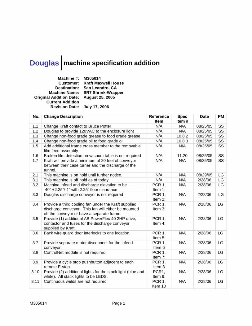
Machine #: M305014 Customer: Kraft Maxwell House
Destination: San Leandro, CA Machine Name: SR7 Shrink-Wrapper
Original Addition Date: August 25, 2005 Current Addition
Revision Date: July 17, 2006
No. Change Description Reference Item
Spec Item #
Date PM
1.1 Change Kraft contact to Bruce Potter N/A N/A 08/25/05 SS
1.2 Douglas to provide 120VAC to the enclosure light N/A N/A 08/25/05 SS 1.3 Change non-food grade grease to food grade grease N/A 10.8.2 08/25/05 SS 1.4 Change non-food grade oil to food grade oil N/A 10.8.3 08/25/05 SS 1.5 Add additional frame cross member to the removable
film feed assembly N/A N/A 08/25/05 SS
1.6 Broken film detection on vacuum table is not required N/A 11.20 08/25/05 SS 1.7 Kraft will provide a minimum of 20 feet of conveyor
between their case turner and the discharge of the tunnel.
N/A N/A 08/25/05 SS
2.1 This machine is on hold until further notice. N/A N/A 08/29/05 LG
3.1 This machine is off hold as of today N/A N/A 2/28/06 LG
3.2 Machine infeed and discharge elevation to be 40” +2.25”/-1” with 2.25” floor clearance
PCR 1, Item 1:
N/A 2/28/06 LG
3.3 Douglas discharge conveyor is not required PCR 1, Item 2:
N/A 2/28/06 LG
3.4 Provide a third cooling fan under the Kraft supplied discharge conveyor. This fan will either be mounted off the conveyor or have a separate frame.
PCR 1, Item 3:
N/A 2/28/06 LG
3.5 Provide (1) additional AB PowerFlex 40 2HP drive, contactor and fuses for the discharge conveyor supplied by Kraft.
PCR 1, Item 4:
N/A 2/28/06 LG
3.6 Back wire guard door interlocks to one location. PCR 1, Item 5:
N/A 2/28/06 LG
3.7 Provide separate motor disconnect for the infeed conveyor.
PCR 1, Item 6
N/A 2/28/06 LG
3.8 ControlNet module is not required. PCR 1, Item 7:
N/A 2/28/06 LG
3.9 Provide a cycle stop pushbutton adjacent to each remote E-stop.
PCR 1, Item 8
N/A 2/28/06 LG
3.10 Provide (2) additional lights for the stack light (blue and white). All stack lights to be LEDS.
PCR1, Item 9:
N/A 2/28/06 LG
3.11 Continuous welds are not required PCR 1, Item 10
N/A 2/28/06 LG
No. Change Description Reference Item
Spec Item #
Date PM
M305014 Page 2
4.1 Add a White Hoffman folding shelf on the inside of the Main Electrical Enclosure
PCR 2, Item1:
N/A 4/21/06 LG
4.2 Change (2) pushbuttons to LED, add LED illumination to (1) pushbutton and add (2) pushbuttons per Paul Kaiser’s e-mail.
PCR 2, Item 2:
N/A 4/21/06 LG
4.3 Change electronically protected output modules to regular outputs and add individual fuses for each output.
PCR 2, Item 3:
N/A 4/21/06 LG
4.4 See attached updated floor plan FP-050491 B (Rev. D dated 4/19/06)
N/A N/A 4/21/06 LG
5.1 See punch list below from machine checkout held on 7/11 – 7/12:
N/A N/A 7/17/06 LG
1. Surge control issues between the lane divider and the pinless metering needs to be resolved to
prevent pushing containers through the pinless metering and causing an overhead sweep overload. Make sure the gearbox ratios and the conveyor speeds are correct. Make sure the sufficient surge photo control is adjusted and functioning properly. Make the HMI as operator friendly as possibly to help prevent an operator from causing a jam.
2. An open guard door on the lane divider should also turn on the red stack light. Other lane divider faults like Lane Divider Jam and Discharge Surge should also turn on the stack light.
3. Make sure the guard door open message is displayed (not safety relay open) when a door is opened. Make sure the E-stop message is displayed (not safety relay open) when an E-stop is activated. The alarm which says “safety relay needs to be reset” appears on the HMI screen occasionally; this message should only appear if the guard doors and e-stops are OK and the Reset pushbutton is press and the safety relay takes more than five seconds to reset. In other words, this alarm should only indicate that the safety relay string is not working properly.
4. Correct the issue of not being able to reset the machine after guard door #16 is opened.
5. Raise the E-stop / Cycle Stop pushbutton enclosure by the magazine to above the handwheels. (These pushbuttons will be operated from a platform).
6. Add an E-stop / Cycle Stop pushbutton enclosure on the discharge operator side of the tray packer.
7. Add an E-stop / Cycle Stop pushbutton enclosure on the infeed operator side of the shrink-wrapper.
8. Cover the exposed shaft on the magazine drive motor.
9. Change rails on the shrink wrapper infeed conveyor to ½” round stock to allow easier removal of a case with open flaps. Kraft Maxwell House’s coders will be mounted above the rails.
10. Gearbox and motor on the shrink-wrapper infeed conveyor is running hot. (Gearbox was at 148 and motor was at 130). Resize and replace gearbox.
11. Move manual air dump on the tray packer so it is accessible from the outside of the guard package. (Mount below the HMI.)
12. Move the manual air dump on the shrink-wrapper so it is accessible from outside the guard package. (Mount above the main electrical enclosure.)
13. Move surge control photo control cables to the inside of the mount. Bundle and tie up the loose ends of the cables.
14. Make sure the guard along the conveyor edge is installed.
15. Guard head shaft of the shrink-wrapper infeed conveyor on the operator side.
No. Change Description Reference Item
Spec Item #
Date PM
M305014 Page 3
16. Add guard over the 1” x 3” frame member under the overhead sweep chain to prevent chain from rubbing on the frame.
17. Add a lead-in to the guides on the funnel chain.
18. The Manual Count pushbutton on the lane divider should not operate if the lane divider is running (over/under clutch is engaged). Program should check that the Metering Belt is not running for a few seconds before allowing the Manual Count button to operate.
19. Remove the center bar on the internal guarding. (Operator side only)
20. Plug all holes on the internal guarding.
21. Correct communication issue between the shrink-wrapper and the tray packer. (Tray packer should stop if shrink-wrapper stops). This issue was caused by forcing the machine to run at 35 cpm. Machine could not drop below 30 cpm to cycle stop.
22. Make sure the tray packer discharge surge photo control is mounted and functioning properly.
23. Check the gaps between the wand tables and the other conveyors. They seem to vary from side to side.
24. Check all the bushings on the shrink wrapper conveyors. Some look like they are backing out.
25. Check into other options to replace the springs on the transfer sheet. (A weight on a cable and a cable reel are two possibilities.)
26. The opening in the guards at the discharge of the lane divider needs to be enlarged to allow room for the 4 lb. container.
27. Polish approximately 6” of the rails just down stream of the lane divider gun.
28. The first split in the rails after the lane divider needs to be reworked. Shorten the stiffener on all the lanes and add a lead-in to prevent scuffing the container.
29. Add a photo control to detect a container out of position before an overhead sweep bar can hit it.
30. Look into replacing the conveyor transfers with something more robust. (Maybe use larger diameter rollers if the containers will still transfer well.)
31. Stiffen up the lane divider guard package to prevent shaking when the lane divider shifts.
32. The outside rails going into the pinless metering section need to have lead-ins to prevent scuffing the container.
33. Adjust the open flap detection photo controls so a minor flap sticking out will also be detected.
34. On both HMI panels (Tray and Shrink), the blue E-stop Reset pushbuttons presently turn dark (off) when the safety relays needed to be reset. These pushbuttons’ lamps should instead flash when the safety relay is not energized. This is done to indicate to the Operator that the Reset pushbutton needs to be pressed before the machine can be restarted. The Reset pushbuttons should be steady illuminated when the Safety relay is satisfied.
35. The “reset” pushbutton in the upper-right-hand corner of each HMI screen needs to be removed from the screen; the functionality of this HMI pushbutton should be incorporated in the blue, hardwired Reset pushbutton. This is true for both the Tray and Shrink machines.
36. After removing the “reset” pushbutton icon from the HMI “Machine” screen (the main screen on the Tray machine HMI), the remaining “go to screen” pushbuttons should be moved upward on the screen, and a new “go to screen” pushbutton needs to be added to allow one-button access to the Current Faults screen. This will keep all the “go to screen” buttons on the right side of the screen, and also allow Operators quicker access to the Current Faults screen.
No. Change Description Reference Item
Spec Item #
Date PM
M305014 Page 4
37. Shrink machine hardwired pushbuttons (Start, Reset) were not working during the test; Douglas stated that they were not wired yet.
38. Shrink machine stack lights (green and amber) did not appear to be working properly.
39. The “startup” horn cycle would occur anytime the hardwired Start pushbutton was pressed on the Tray machine, even if the machine was not ready to be started. This horn cycle needs to occur only if the machine is actually starting up.
40. Low magazine and Low Glue need to trigger the blue stack light beacon to flash on the Tray machine (not tested). Low film on the Shrink machine should make the Shrink blue stack light flash (not tested).
41. Tray machine failed to alarm three (3) tray blanks missed at the setup in-a-row.
42. Douglas needs to confirm that the alarm structure for all servo axes in the Shrink machine work in similar fashion to the alarms in the Tray machine (that is, each servo should have all specific alarms generated on the HMI, not just a single “servo fault” alarm). This was confirmed by Matt at the 7/12/2006 test on the Tray machine, but not on the Shrink machine due to time constraints.
43. Hardwired pushbuttons on the HMI panel should be illuminated according to the following guidelines (for both the Tray and Shrink machine):
a. Start PB (green): Steady on when the machine is running (as is currently). Flash when the machine is not running but the machine will autostart when an upstream or downstream permissive is resolved. Also flash if the machine is recovering (servos repositioning) and also flash if the machine is in a startup sequence (such as when the Start pushbutton is being held in during a start sequence). Off if the machine is stopped and not in a restart sequence.
b. Stop PB (red): Steady on when the machine is stopped (and not in a restart sequence). Off any other time.
c. Reset PB (blue): Flashing if the safety relay is not energized. Steady-on if the safety relay is energized. Note for the pushbutton on the Land Divider; this one will be steady-on only if the Safety Relay is energized and the Land Divider Guard Door Relay is energized (otherwise flashing).
44. The five-beacon stack light has a generic usage, as follows:
a. Red: Flashing if the machine is faulted (but not low material warnings… just faults).Steady on if the machine is stopped.
b. Amber: Steady on if the machine is stopped but ready to be started by the Operator (“ready to start”).
c. Green: Steady-on if the machine is running. If the machine is stopped: Flashing Fast (3 Hz) if the machine is ready to autostart (without Operator intervention) but waiting for a downstream permissive. Flashing Fast if the machine is ready autostart (without Operator intervention) but waiting for an upstream permissive. Note the Downstream permissive characteristic has priority over the Upstream characteristic.
d. Blue: Flashing if low material (low glue, low film, low cartons).
e. White: energized if no other lights are energized (red, amber, green, or blue). Programmer must take into consideration that the white light never should flash, only be solid on or solid off….
45. Ship the pallet of product that is in trays and shrink wrapped to San Leandro with the machine.
No. Change Description Reference Item
Spec Item #
Date PM
M305014 Page 5
46. The other pallet of product that was to be shipped to Jacksonville can be used for additional testing if required. After testing is completed, the product wrapped with Jacksonville’s film needs to be sent to Julio at Jacksonville.
47. Kraft Maxwell House (Gene) will return for second checkout on July 25th. Machine will be skidded on or before July 28th, 2006.
6.1 Program the Lane Divider so it cannot shift if you have had a jam.
N/A N/A 07/26/06 LG
6.2 Add an Allen-Bradley 2 color stack light (red & green) to the lane divider
PCR 5, Item 1:
N/A 07/26/06 LG
6.3 Remove 6” from the magazine support on the operator side to allow easier access to the magazine.
PCR 5, Item 2:
N/A 07/26/06 LG
6.4 Check amp load and temp. shrink wrapper infeed conveyor when loaded with product. Gearbox reached a max temp of 110 degrees
Motor reached a max temp of 131 degrees
N/A N/A 07/26/06 LG
6.5 Add shoe to the 1 x 3 frame member at the slip sheet area.
N/A N/A 07/26/06 LG
6.6 Add the cable reels, used on the slip sheet, to the spare parts list.
N/A N/a 07/26/06 LG
6.7 E-mail drawing of the infeed brake/metering belts take-up’s to Gene Gift. (Ron Moore to drawing)
N/A N/A 07/26/06 LG
6.8 1-Pallet of product to be shipped to Jacksonville, FL, this is to be fully crated and shipped LTL
N/A N/A 07/26/06 LG
6.9 1-Pallet of product to be shipped with the machine, half the products on the pallet to be wrapped with film supplied by San Leandro and other half the pallet to be wrapped with film supplied by Jacksonville. This pallet will shipped with the machine.
N/A N/A 07/26/06 LG
6.10 Set the magazine to run 2” tall trays prior to shipment N/A N/A 07/26/06 LG
6.11 All remaining product full or empty is to be placed on pallets and will be disposed of per Gene Gift’s instructions