Next Generation Architecture One NGN architecture for VoIP with centralized call processing decomposes the functional elements of a traditional circuit switch into specialized components with open interfaces. Following are the key logical elements of this reconstruction are the following: The MG handles the media, or bearer, interface. It converts media from the format used in one network to the format required in another network. For example, it can terminate the TDM trunks from the PSTN, packetize and optionally compress the audio signals, and then deliver the packets to the IP network using the Real Time Protocol (RTP) [120 ]. The MGC (also known as a Call Agent) contains the call processing. In addition, it manages the resources of the MGs that it controls. The MGC controls the MG using a control protocol to set up the RTP connections and control the analog or TDM endpoint in the MG. The SG sits at the edge of an IP network and terminates circuit-switched network signaling, such as SS7 or ISDN, from the circuit-switched network. It transports, or backhauls, this signaling to the MGC or other IP-based application endpoint. Figure 14-1 shows an example of these logical elements and their connections. Figure 14-1. NGNs—Sample Architecture [View full size image] As Figure 14-1 shows, the evolution of specialized components provided open interfaces between these logical elements. The Internet Engineering Task Forces (IETF) created two working groups to address these open interfaces at the same time that ITU-T SG16 began to study the MGC to MG interface. Thus, the definition of the bearer control protocol between the MG and the MGC became a joint effort by the IETF MeGaCo (MGC) Working Group and the ITU-T SG16. The output from these groups is known as the Megaco [RFC 3015] [121 ] protocol in the IETF, and the H.248 [122 ] protocol in the ITU-T.
Transcript
Next Generation Architecture
One NGN architecture for VoIP with centralized call processing decomposes the functional elements of a traditional circuit switch into specialized components with open interfaces. Following are the key logical elements of this reconstruction are the following:
The MG handles the media, or bearer, interface. It converts media from the format used in one network to the format required in another network. For example, it can terminate the TDM trunks from the PSTN, packetize and optionally compress the audio signals, and then deliver the packets to the IP network using the Real Time Protocol (RTP) [120].
The MGC (also known as a Call Agent) contains the call processing. In addition, it manages the resources of the MGs that it controls. The MGC controls the MG using a control protocol to set up the RTP connections and control the analog or TDM endpoint in the MG.
The SG sits at the edge of an IP network and terminates circuit-switched network signaling, such as SS7 or ISDN, from the circuit-switched network. It transports, or backhauls, this signaling to the MGC or other IP-based application endpoint.
Figure 14-1 shows an example of these logical elements and their connections.
Figure 14-1. NGNs—Sample Architecture
[View full size image]
As Figure 14-1 shows, the evolution of specialized components provided open interfaces between these logical elements. The Internet Engineering Task Forces (IETF) created two working groups to address these open interfaces at the same time that ITU-T SG16 began to study the MGC to MG interface. Thus, the definition of the bearer control protocol between the MG and the MGC became a joint effort by the IETF MeGaCo (MGC) Working Group and the ITU-T SG16. The output from these groups is known as the Megaco [RFC 3015] [121] protocol in the IETF, and the H.248 [122] protocol in the ITU-T.
Also worth mentioning is a precursor to Megaco protocol: the Media Gateway Control Protocol (MGCP) [RFC 3435] [123].
NOTE
MGCP was originally published in RFC 2705, which has now been replaced by RFC 3435.
MGCP can also be used as a control protocol between an MGC MGCU (TG) and an MG. While MGCP is defined by an Informational (versus standards track) RFC, it is commonly used in many products today because the specification was available before Megaco and H.248 were finished. Both MGCP and Megaco/H.248 assume that the call control intelligence is outside the MGs and that the MGC handles it.
Closely related to the MGCP protocol are the PacketCable protocols, Network-Based Call Signaling (NCS) and PSTN Gateway Call Signaling Protocol (TGCP). These protocols provide functionality similar to MGCP for cable-based networks.
The IETF SigTran Working Group focused on the SG to MGC open interface. The Working Group produced a set of standard protocols to address the needs and requirements of this interface.
SigTran
There has been interest in interworking SS7 and IP for quite some time. However, the initial solutions were proprietary. This began to change in the late 1990s, when an effort to standardize Switched Circuit Network (SCN) signaling (SS7) over IP transport began in the IETF.
The IETF SigTran Working Group was founded after a Birds of a Feather (BOF) session, which was held at the Chicago 1998 IETF meeting, to discuss transport of telephony signaling over packet networks. The result of the BOF was the creation of the SigTran Working Group to do the following:
Define architectural and performance requirements for transporting SCN signaling over IP. Evaluate existing transport protocols, and, if necessary, define a new transport protocol to
meet the needs and requirements of transporting SCN signaling.
Define methods of encapsulating the various SCN signaling protocols.
The SigTran Working Group first met at the Orlando 1998 IETF meeting.
The SigTran Working Group defined the framework architecture and performance requirements in RFC 2719 [126]. The framework included the concept of reconstructing the traditional circuit switch into MGC, MG, and SG elements, thereby separating the signaling and the media control plane.
The framework document identified three necessary components for the SigTran protocol stack:
A set of adaptation layers that support the primitives of SCN telephony signaling protocols A common signaling transport protocol that meets the requirements of transporting
telephony signaling
IP [127] network protocol
Figure 14-2 shows the three layers of the protocol stack.
Further functional requirements were defined for the transport protocol and adaptation layers. The transport had to be independent of the telephony protocol it carried, and, more importantly, had to meet the stringent timing and reliability requirements of that telephony protocol.
The Working Group began evaluating the two commonly used transport protocols, User Datagram Protocol (UDP) [128] and Transport Control Protocol (TCP) [129], against these requirements. UDP was quickly ruled out because it did not meet the basic requirements for reliable, in-order transport. While TCP met the basic requirements, it was found to have several limitations. A team of engineers from Telcordia (formerly Bellcore) completed an analysis of TCP against SS7's performance and reliability requirements. Their analysis was documented in an IETF draft [130], which introduced the following limitations of TCP:
Head-of-line blocking— Because TCP delivery is strictly sequential, a single packet loss can cause subsequent packets to also be delayed. The analysis showed that a 1% packet loss would cause 9% of the packets being delayed greater than the one-way delay time.
Timer granularity— While this is not a limitation of the TCP protocol, it is a limitation of most implementations of TCP. The retransmission timer is often large (typically one second) and is not tunable.
The Working Group noted additional TCP limitations, including the following:
A lack of built-in support for multihoming. This support is necessary for meeting reliability requirements, such as five 9s and no single point of failure.
Also, because of a timer granularity issue and the lack of a built-in heartbeat mechanism, it takes a long time to detect failure (such as a network failure) in a TCP connection.
Because of the deficiencies of UDP and TCP, a new transport protocol, Stream Control Transmission Protocol (SCTP) [131], was developed for transporting SCN signaling. Note that SCTP is a generic transport that can be used for other applications equally well.
Stream Control Transmission Protocol (SCTP)
The SigTran Working Group presented several proposals for a new transport protocol. One proposal was Multinetwork Datagram Transmission Protocol (MDTP), which became the foundation for SCTP. RFCNext Generation Network2960 defines SCTP, which has been updated with RFC 3309 [132] to replace the checksum mechanism with a 32-bit CRC mechanism. Further, there is an SCTP Implementers Guide [133] that contains corrections and clarifications to RFC 2960.
Acknowledged error-free, nonduplicated transfer of user data Data segmentation to conform to path MTU size (dynamically assigned)
Ordered (sequential) delivery of user messages on a per "stream" basis
Option for unordered delivery of user messages
Network-level fault tolerance through the support of multihoming
Explicit indications of application protocol in the user message
Congestion avoidance behavior, similar to TCP
Bundling and fragmenting of user data
Protection against blind denial of service and blind masquerade attacks
Graceful termination of association
Heartbeat mechanism, which provides continuous monitoring of reachability
SCTP is a connection-oriented protocol. Each end of the connection is a SCTP endpoint. An endpoint is defined by the SCTP transport address, which consists of one or more IP addresses and an SCTP port. The two endpoints pass state information in an initialization procedure to create an SCTP association. After the association has been created, user data can be passed. Figure 14-3 provides an example of two SCTP endpoints in an association.
Figure 14-3. SCTP Endpoints in an Association
In Figure 14-3, Host A has endpoint [10.82.82.4, 10.82.83.4 : 2905] and Host B has endpoint [10.82.82.24, 10.82.83.24 : 2905]. The association is the combination of the two endpoints.
The following sections discuss how SCTP addresses the deficiencies of TCP that are related to meeting the requirements for delivering telephony signaling over IP. For additional details about the internals of SCTP, the Stream Control Transmission Protocol, A Reference Guide, by Randall Stewart and Qiaobing Xie, is a good resource.
SCTP uses streams as a means of decreasing the impact of head-of-line blocking. In SCTP, a stream is a unidirectional channel within an association. Streams provide the ability to send separate sequences of ordered messages that are independent of one another.
Figure 14-4 provides an example of head-of-line blocking with TCP. When packet 2 is dropped, packets 3 to 5 cannot be delivered to the application because TCP provides in-order delivery.
Figure 14-4. Example of Head-of-Line Blocking in TCP
SCTP provides the ability to have multiple streams within an association. Each stream provides reliable delivery of ordered messages that are independent of other streams.Figure 14-5 shows an example of how SCTP can help resolve head-of-line blocking. In this example, packet 2 is dropped again. However, because packets 3, 4, and 5 belong to a different stream, they can be delivered to the application without delay.
Figure 14-5. Use of Streams in SCTP to Avoid Head-of-Line Blocking
Failure Detection
Quick failure detection and recovery is important for meeting the performance and reliability requirements that are specified for transporting SCN signaling. For a multihomed host, two types of failures can occur:
One or more destination addresses in the peer endpoint become unavailable or unreachable.
The peer endpoint becomes unavailable or unreachable.
A destination address can become unreachable for one of several reasons. First, there could be a failure in the network path to the destination address, or a failure in the Network Interface Card (NIC) that supports the destination address. Likewise, a peer endpoint can become unavailable for several reasons. By definition, the peer endpoint is unavailable or unreachable if all of its destination addresses are unavailable or unreachable. SCTP provides two mechanisms for detecting failures:
1. Use of the Path.Max.Retrans threshold, which is the maximum number of consecutive retransmission that are allowed for a path.
2. Use of the heartbeat mechanism.
When an endpoint sends a data message to a particular destination address, an acknowledgement is expected in return. If the acknowledgement has not been received when the retransmission timer expires, SCTP increases an error counter for that destination address and then retransmits the data message to the same destination or to another destination address, if one is available. The destination address is considered unreachable if the error counter reaches a defined threshold (Path.Max.Retrans).
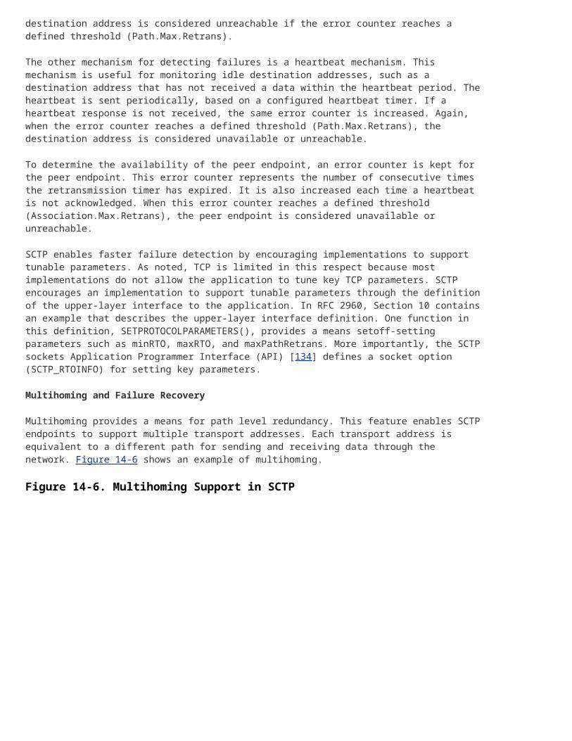
The other mechanism for detecting failures is a heartbeat mechanism. This mechanism is useful for monitoring idle destination addresses, such as a destination address that has not received a data within the heartbeat period. The heartbeat is sent periodically, based on a configured heartbeat timer. If a heartbeat response is not received, the same error counter is increased. Again, when the error counter reaches a defined threshold (Path.Max.Retrans), the destination address is considered unavailable or unreachable.
To determine the availability of the peer endpoint, an error counter is kept for the peer endpoint. This error counter represents the number of consecutive times the retransmission timer has expired. It is also increased each time a heartbeat is not acknowledged. When this error counter reaches a defined threshold (Association.Max.Retrans), the peer endpoint is considered unavailable or unreachable.
SCTP enables faster failure detection by encouraging implementations to support tunable parameters. As noted, TCP is limited in this respect because most implementations do not allow the application to tune key TCP parameters. SCTP encourages an implementation to support tunable parameters through the definition of the upper-layer interface to the application. In RFC 2960, Section 10 contains an example that describes the upper-layer interface definition. One function in this definition, SETPROTOCOLPARAMETERS(), provides a means setoff-setting parameters such as minRTO, maxRTO, and maxPathRetrans. More importantly, the SCTP sockets Application Programmer Interface (API) [134] defines a socket option (SCTP_RTOINFO) for setting key parameters.
Multihoming and Failure Recovery
Multihoming provides a means for path level redundancy. This feature enables SCTP endpoints to support multiple transport addresses. Each transport address is equivalent to a different path for sending and receiving data through the network. Figure 14-6 shows an example of multihoming.
In the case of multihoming, one network path is selected as the primary path. Data is transmitted on the primary path while that path is available. If a packet gets dropped—for instance, because of a failure in the path—the retransmission should be sent on the alternate path. Figure 14-7 provides an example based on the diagram in Figure 14-6, with the primary path between IP1 and IP3 (the 10.82.82.x network) and the alternate path between IP2 and IP4 (the 10.82.83.x network). In this example, the packet with Transmission Sequence Number (TSN) 1 is retransmitted on the alternate path.
Figure 14-7. Failure Recovery Example
Retransmitting on the alternate path decreases failure recovery time. Further, if the primary path fails, the alternate path is automatically selected as the primary path. The path failure recovery mechanism is completely transparent to the application that uses SCTP.
Proposed Additions
The IETF Transport Working Group proposes two promising additions to the SCTP protocol:
The first proposal is to allow for IP address information reconfiguration on an existing association. This feature can be useful for hardware that provides for hot swap of an Ethernet card, for example. A new Ethernet card could be added and the Ethernet card's IP address could then be added to the association without requiring system downtime.
The second proposal allows for partially reliable transport on a per message basis. In other words, the application can determine how a message should be treated if it needs to be retransmitted. For instance, the application can decide that a message is stale and no longer useful if it has not been delivered for two seconds. SCTP then moves past that message and stops retransmitting it.
User Adaptation (UA) Layers
The User Adaptation (UA) layers encapsulate different SCN signaling protocols for transport over an IP network using SCTP. While each UA layer is unique in terms of the encapsulation because of the differences of the signaling protocols themselves, following are some common features among all UA layers:
Support for seamless operation of the UA layer peers over an IP network. Support for the primitive interface boundary of the SCN lower layer, which the UA layer
replaces. For example, M2UA supports the primitive interface boundary that MTP Level 2 supports.
Support for the management of SCTP associations.
Support for asynchronous reporting of status changes to layer management.
The SigTran Working Group has defined several UA layers, which include the following:
The MTP Level 2 User Adaptation (M2UA) layer is defined for the transport of MTP Level 3 messages between a SG and a MGC or IP database.
The MTP Level 3 User Adaptation (M3UA) layer is defined for the transport of SS7 User Part messages (such as ISUP, SCCP, and TUP) between an SS7 SG and a MGC or other IP Signaling Point (IPSP).
The SCCP User Adaptation (SUA) layer is defined for the transport of SCCP User Part messages (such as TCAP and RANAP) from an SS7 SG to an IP-based signaling node or database, or between two endpoints in the same IP network.
The MTP Level 2 Peer Adaptation (M2PA) layer is defined for the transport of MTP Level 3 data messages over SCTP. M2PA effectively replaces MTP Level 2. It provides the ability to create an IP-based SS7 link.
The ISDN User Adaptation (IUA) layer is defined for the transport of Q.931 between an ISDN SG and a MGC. IUA supports both Primary Rate Access and Basic Rate Access lines.
Each of these adaptation layers will be discussed in detail, with the exception of IUA because it is beyond the scope of this book. Other proposed adaptation layers (such as DPNSS/DASS2 DUA [144] UA and V5.2 V52UA [145] UA) are being worked on in the SigTran Working Group; however, like IUA, those adaptation layers are beyond the scope of an SS7 discussion.
When these adaptation layers were being developed, it became evident that some terminology and functionality were common, with the exception of M2PA. There was an effort to keep the UA documents synchronized with common text for these terms and functional discussions.
The UAs introduce some new terminology that did not exist in the SS7 world. Some of these terms are common across all of the SS7 UAs; therefore, it is worth discussing them before starting with the adaptation layers. Following are the definitions of these terms, provided by RFC 3332 [137]:
Application Server (AS)— A logical entity that serves a specific Routing Key. An example of an Application Server is a virtual switch element that handles all call processing for a unique range of PSTN trunks, identified by an SS7 SIO/DPC/OPC/CIC_range. Another example is a virtual database element, handling all HLR transactions for a particular SS7 DPC/OPC/SCCP_SSN combination. The AS contains a set of one or more unique ASPs, of which one or more is normally actively processing traffic. Note that there is a 1:1 relationship between an AS and a Routing Key.
Application Server Process (ASP)— A process instance of an Application Server. An ASP serves as an active or backup process of an Application Server (for example, part of a distributed virtual switch or database). Examples of ASPs are processes (or process instances) of MGCs, IP SCPs, or IP HLRs. An ASP contains an SCTP endpoint and can be configured to process signaling traffic within more than one Application Server.
Signaling Gateway Process (SGP)— A process instance of a SG. It serves as an active, backup, load-sharing, or broadcast process of a SG.
Signaling Gateway (SG)— An SG is a signaling agent that receives/sends SCN native signaling at the edge of the IP network. An SG appears to the SS7 network as an SS7 Signaling Point. An SG contains a set of one or more unique SG Processes, of which one or more is normally actively processing traffic. Where an SG contains more than one SGP, the SG is a logical entity, and the contained SGPs are assumed to be coordinated into a single management view to the SS7 network and the supported Application Servers.
IP Server Process (IPSP)— A process instance of an IP-based application. An IPSP is essentially the same as an ASP, except that it uses M3UA in a point-to-point fashion. Conceptually, an IPSP does not use the services of a SG node.
Figure 14-8 puts these terms into context. In this diagram, the SG consists of two SGP. Each SGP is a separate hardware platform. The SGPs share a point code. The MGC supports the Application Server, which is a logical entity. For example, the Application Server is commonly provisioned as a point code and service indicator (SI) for M3UA. For more information, see the Application Servers section.
Finally, the ASP runs on the MGC platform that handles the UA protocol stack. In this diagram, the MGC consists of two hosts, each of which has an ASP. Therefore, the AS consists of ASP1 and ASP2. Depending on the MGC redundancy model (Active-Standby, Load Share, or Broadcast), one or more of the ASPs are Active (or able to send and receive user data) for the AS at any given time.
In addition to the common terminology, the text related to how the SG and SGPs manage the AS and ASP states is common in all of the UA layers (again, with the exception of M2PA).
Routing Keys and Interface Identifiers
The SG must be capable of distributing incoming SS7 data messages to the appropriate Application Server. For M3UA and SUA, the SG performs this routing based on statically or dynamically defined Routing Keys. From RFC 3332, a Routing Key is defined as:
A Routing Key describes a set of SS7 parameters and parameter values that uniquely define the range of signaling traffic to be handled by a particular Application Server. Parameters within the Routing Key cannot extend across more than a single Signaling Point Management Cluster.
The Routing Key has a one-to-one relationship with an Application Server. Further, it is uniquely identified by a 32-bit value, called a Routing Context.
The Routing Key is used to distribute messages from the SS7 network to a specific Application Server. According to SigTran, this key can be any combination of the following SS7 routing information:
Network Indicator (NI) Service Indicator (SI)
Destination Point Code (DPC)
Originating Point Code (OPC)
Subsystem number (SSN)
Refer to Chapter 7, "Message Transfer Part 3 (MTP3)," for more information on NI, SI, OPC and DPC. Refer to Chapter 9, "Signaling Connection Control Part (SCCP)," for more information on SSN.
A SG does not have to support all of these parameters.
Figure 14-9 provides an example of how a SG might be provisioned with Routing Key, Routing Context, Application Server, and ASP information. This diagram contains a mated pair of SGs that also act as STPs. Each SG has the same Application Server database. When a SG receives a message, it tries to match that message against its database. In the example, a message arrives for DPC 1.1.1 at SG2. This message matches Application Server CHICAGO, so it is sent to ASP ASP1.
Figure 14-9. Routing Key Example
NOTE
The SGs in this diagram are labeled ITP. The ITP, or IP Transfer Point, is a Cisco SG product offering. For more information, please refer to the following Web site:
For M2UA and IUA, the SG uses an Interface Identifier value to determine the distribution of incoming messages. The Interface Identifier is unique between the SG and the ASP. Unlike
Routing Keys, there can be a many-to-one relationship between Interface Identifiers and Application Servers. In other words, an Application Server can contain more than one Interface Identifiers. Also, Interface Identifiers can be a 32-bit integer value or an ASCII string.
To give meaning to the Interface Identifier, one suggestion is to use the physical slot and port the SG's information to create the 32-bit value or ASCII string. Figure 14-10provides an example of how Interface Identifiers would be configured on the SG. Note that the MGC must have the same Interface Identifiers provisioned. In this example, AS CANTON contains four Interface Identifiers, with each one mapped to a SS7 link.
Figure 14-10. Interface Identifier Example
Finally, because M2PA is a peer-to-peer arrangement between two IP-based SS7 Signaling Points, there is no need for message distribution or routing. Therefore, there is not a concept of Routing Key or Interface Identifier.
MTP Level 3 UA (M3UA)
M3UA [137] provides for the transport of MTP Level 3-user part signaling (such as ISUP and SCCP) over IP using SCTP. RFC 3332 defines and supplements it with an Implementers Guide [138]. M3UA provides for seamless operation between the user part peers by fully supporting the MTP Level 3 upper-layer primitives. M3UA can be used between an SG and an MGC or IP-resident database, or between two IPSP.
The most common use for M3UA is between a SG and a MGC or IP-resident databases (such as SCPs). The SG receives SS7 signaling over standard SS7 links. It terminates MTP Levels 1 to 3 and provides message distribution, or routing, of the user part messages that is destined for MGCs or IP-resident databases. The MGCs can send to other MGCs via the SG.
Figure 14-11 shows the protocol stacks at each network element for using M3UA between a SG and a MGC. The SEP, or SEP, is a node in the SS7 network. The NIF, or Nodal Interworking Function, provides for the interworking of SS7 and IP. RFC 3332 does not define the functionality of the NIF because it was considered out of scope.
The M3UA on the MGC or IP-resident database supports the MTP Level upper-layer primitives so the user parts are unaware that MTP is terminated on the SG. The MTP service primitives [49] consist of the following:
MTP Transfer request and indication MTP Pause indication
MTP Resume indication
MTP Status indication
The MTP Transfer primitive is used to pass user data. MTP Pause indicates that an Affected Point Code is Unavailable, and MTP Resume indicates that an Affected Point Code is Available. MTP Status provides congestion and User Part Availability information on an Affected Point Code. Later, in the Messages and Formats description of M3UA messages, it will be clear how these primitives are supported.
The M3UA layer on the SGP must maintain the state of all the configured ASPs and ASes. M3UA at the ASP must maintain the state of all configured SGPs and SGs.
The M3UA layer on the SG supports message distribution of incoming messages from the SS7 and IP-based sources. The distribution is based on matching the incoming message against the Routing Keys. When a Routing Key is selected, the Application Server state is checked to see if it is active. An Active Application Server has at least one ASP that is ready to receive data messages. If the Application Server is active, the message is forwarded to the appropriate ASP(s) that support the AS.
To determine the appropriate ASP, the SG must take into account the AS's traffic mode. There are three possible traffic modes: Override, Load Share, and Broadcast. Override traffic mode is basically an Active-Standby arrangement in which one ASP is active for receiving data messages and one or more ASPs are Standby. In this case, the SGP sends to the active ASP. In Load Share mode, one or more ASPs can be active. The SGP load shares across the active ASPs using an implementation-specific algorithm. Finally, in Broadcast mode, one or more ASPs can be active, and the SGP sends the data message to each active ASP.
The M3UA layer on the ASP must also make decisions about the distribution of outgoing messages. To do so, the M3UA layer maintains the availability and congestion state of the routes to remote SS7 destinations. An M3UA route refers to a path through an SG to an SS7 destination.
If an SS7 destination is available through more than one route (more than one SG), the M3UA layer must perform some additional functions. In addition to keeping the state of each route, M3UA must also derive the overall state from the individual route states. The derived state is provided to the upper layer. Also, if each individual route is available, the M3UA should load balance across the available routes. Further, if the SG consists of more than one SGP, M3UA should load share across the available SGPs.
The M3UA layer at the SGP and ASP must maintain the state of each SCTP association. M3UA uses a client-server model with the ASP defaulting to the client and SG as the server. However, both SG and ASP should be able to be provisioned as the client or server. The client side of the relationship is responsible for establishing the association.
During the establishment of the association, several inbound and outbound streams are negotiated between the SCTP peers. The M3UA layer at both the SGP and ASP can assign data traffic to individual streams based on some parameter that ensures proper sequencing of messages, such as SLS.
M3UA has an Internet Assigned Numbers Authority (IANA) registered port number of 2905. It also has an IANA registered SCTP payload protocol identifier value of 3.
Messages and Formats
All of the UA layers use the same common header format. The common header includes the version, message type, message class, and message length. Figure 14-12 shows the format of the common message header.
Figure 14-12. UA Common Message Header
The RFC provides the list of currently defined message classes and types. Several values are reserved for future extensions. IANA provides a registry of these extensions at the following Web site:
http://www.iana.org/assignments/sigtran-adapt
Table 14-1 lists the M3UA message classes and types.
Table 14-1. M3UA Message Classes and Types
Msg Class Value Message Class and Type Names Msg Type Value
Service Indicator Octet (SIO), SLS, and ISUP information. In addition, it can contain a Routing Context, Network Appearance, and/or Correlation Identifier.
The Routing Context associates the message with a configured Routing Key, or Application Server. It must be present if the SCTP association supports more than one Application Server.
The Network Appearance provides the SS7 network context for the point codes in the message. It is useful in the situation in which a SG is connected to more than one SS7 network and the traffic associated with these different networks is sent to the ASP over a single SCTP association. An example is the case of an SG in multiple national networks. The same Signaling Point Code value can be reused within these different national networks, and Network Appearance is needed to provide uniqueness. The Network Appearance might be necessary to indicate the format of the OPC and DPC.
The Correlation Identifier provides a unique identifier for the message that the sending M3UA assigns.
SS7 Signaling Network Management (SSNM) Messages
The SSNM messages map to the other MTP primitives: MTP Pause, MTP Resume, and MTP Status. In addition, there is support for the ASP to audit the state of an SS7 destination.
The Routing Context and Network Appearance parameters are optional in these messages just as they are in the Protocol Data message. The same rules apply.
The following are SSNM messages:
Destination Unavailable (DUNA)— The DUNA message maps to the MTP Pause primitive. The SGP sends it to all concerned ASPs to indicate that one or more SS7 destinations are unreachable. The message can be generated from an SS7 network event if an ASP sends a message to an unavailable SS7 destination or when the ASP audits the SS7 destination. The DUNA contains the Affected Point Code parameter, which allocates 24 bits for the point code and 8 bits for a mask field. Figure 14-14 shows the Affected Point Code parameter.
Figure 14-14. Affected Point Code Parameter
The mask field indicates a number of bits in the point code value that are wild-carded. For
example, ANSI networks use the mask field to indicate that all point codes in a cluster are unavailable by setting the mask field to a value of 8.
The DUNA can also contain a Network Appearance, Routing Context, and/or Info String parameters. Again, the Routing Context must be sent if the SCTP association supports more than one Application Server. The Routing Context parameter contains all of the Routing Contexts that apply to concerned traffic flows that are affected by the state change of the SS7 destination.
Destination Available (DAVA)— The DAVA message maps to the MTP Resume primitive. An SGP sends it to all concerned ASPs to indicate that one or more SS7 destinations are reachable. The message can be generated from an SS7 network event, or when the ASP audits the SS7 destination. It contains the same parameters as the DUNA.
Destination State Audit (DAUD)— The DAUD message does not map to an MTP primitive. It is sent by the ASP to audit SS7 destinations that are of interest. The parameters in the message are identical to those in the DUNA.
Signaling Congestion (SCON)— The SCON message maps to the MTP Status primitive. The SGP sends it to all concerned ASPs when the SG determines or is notified that the congestion state of an SS7 destination has changed, or in response to an ASP's Protocol Data or DAUD message. Like the DUNA and DAVA, it contains the Affected Point Code, Routing Context, Network Appearance, and Info String parameters. In addition, it includes optional Concerned Point Code and Congestion Indication parameters.
Destination User Part Unavailable (DUPU)— The DUPU message maps to the MTP Status primitive. The SGP sends it to concerned ASPs to indicate the availability of a user part. It contains the same parameters as the DUNA message, and a User/Cause parameter that provides the user part that is affected and the unavailability cause.
Destination Restricted (DRST)— –The SGP sends the DRST message to concerned ASPs to indicate that the SG has determined that one or more SS7 destinations are restricted from that SG's point of view. It is also sent in response to a DAUD, if appropriate. It contains the same parameters as the DUNA message.
ASPSM and ASPTM Messages
Together, the ASPSM and ASPTM messages provide a means of controlling the state of the ASP. Further, the state of the ASP feeds into the state machine of each AS it serves. Therefore, these messages also provide a means of controlling the state of the AS.
As the RFC suggested, an ASP can have one of three states: ASP-Down, ASP-Inactive, or ASP-Active. ASP-Down indicates that the ASP is unavailable. ASP-Inactive indicates that the ASP is available but is not yet ready to send or receive data traffic. Finally, ASP-Active indicates that the ASP is available and desires to send and receive data traffic.
The RFC also suggests the following AS states: AS-Down, AS-Inactive, AS-Pending, and AS-Active. The AS-Down state indicates that all ASPs in the AS are in the ASP down state. The AS-Inactive state indicates that at least one ASP in the AS is in the ASP-Inactive state, and that no ASPs in the AS are in the ASP active state. The AS-Active state indicates that at least one ASP in the AS is in the ASP-Active state. The AS-Pending state is a transitory state; it is entered when the last active ASP transitions to ASP inactive or ASP-Down. It provides a means for the AS to recover without losing any messages if another ASP quickly becomes active.
Further, to provide an additional reliability measure, an optional heartbeat mechanism ensures that the M3UA peers are still available. Either side can initiate a heartbeat message, and the other
side must respond with a heartbeat acknowledgement.
Following are ASPSM messages:
ASP Up message— The ASP Up message is used to transition from ASP down to ASP-INACTIVE.
ASP Up Acknowledge message— The ASP Up Acknowledge message is sent in response to an ASP Up message. The ASP does not consider itself in the ASP inactive state until the acknowledgement is received.
ASP Down message— The ASP Down message is used to transition to ASP down from any other state.
ASP Down Acknowledge message— The ASP Down Acknowledge message is sent in response to an ASP Down message. The SGP can also asynchronously send this message if, for instance, the SGP is going out of service. The ASP transitions to ASP down when it receives this message.
Heartbeat message— The Heartbeat message is used to query if the peer is still available.
Heartbeat Acknowledge message— The Heartbeat Acknowledge message is sent in response to the Heartbeat message.
The following are ASPTM messages:
ASP Active message— The ASP Active message is used to transition from ASP inactive to ASP active.
ASP Active Acknowledge message— The ASP Active Acknowledge message is sent in response to an ASP Active message. The ASP does not consider itself in the ASP active state until the acknowledgement is received.
ASP Inactive message— The ASP Inactive message is used to transition from ASP active to ASP inactive.
ASP Inactive Acknowledge message— The ASP Inactive Acknowledge message is sent in response to an ASP Inactive message. This message can also be sent asynchronously by the SGP if, for instance, an Application Server is taken out of service. The ASP transitions to ASP inactive when it receives this message.
Management (MGMT) Messages
There are two MGMT messages: Notify and Error.
The Error message provides a means of notifying the peer of an error event associated with a received message. There are a few errors worth noting because they can indicate a configuration error between the peers: "Invalid Routing Context," "Invalid Network Appearance" and "No Configured AS for ASP" errors.
The Notify message is used to notify appropriate ASPs in the ASP inactive state of Application Server state changes. It can also indicate a lack of resources for load share or that an alternate ASP has become active for an Application Server(s). Finally, it can be used to indicate an ASP failure.
Routing Key Management (RKM) Messages
As noted, Routing Keys can be statically or dynamically provisioned. The means for static provisioning is outside the scope of M3UA, but it could include a Command Line Interface (CLI) or network management system.
The RKM messages provide a means for dynamic provisioning of Routing Keys from an ASP to an SGP or between two IPSPs. These messages and procedures are optional so they do not have to be implemented by a SG or MGC:
Registration Request and Response messages— The Registration Request message is used to register a Routing Key with the SGP or peer IPSP. The Registration Response is used to provide a response (success or failure) to the registration. Included in the response is the Routing Context assigned to the Routing Key.
Deregistration Request and Response messages— The Deregistration Request message is used to deregister a Routing Key with the SGP or peer IPSP. It must contain the Routing Context provided in the Registration Response message. The Deregistration Response is used to respond (success or failure) to the deregistration.
SS7/C7 Variant Specifics
Mostly, M3UA is independent of the SS7/C7 variant that it is transporting. However, there are parameters that depend on the variant.
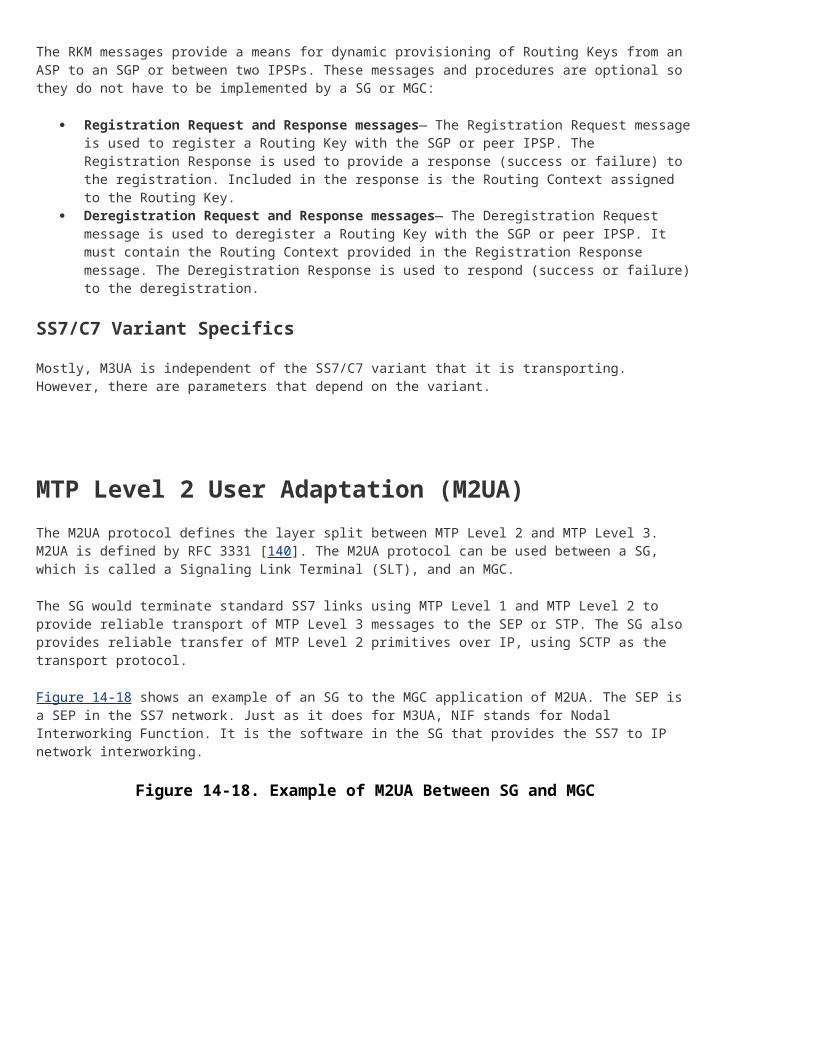
MTP Level 2 User Adaptation (M2UA)
The M2UA protocol defines the layer split between MTP Level 2 and MTP Level 3. M2UA is defined by RFC 3331 [140]. The M2UA protocol can be used between a SG, which is called a Signaling Link Terminal (SLT), and an MGC.
The SG would terminate standard SS7 links using MTP Level 1 and MTP Level 2 to provide reliable transport of MTP Level 3 messages to the SEP or STP. The SG also provides reliable transfer of MTP Level 2 primitives over IP, using SCTP as the transport protocol.
Figure 14-18 shows an example of an SG to the MGC application of M2UA. The SEP is a SEP in the SS7 network. Just as it does for M3UA, NIF stands for Nodal Interworking Function. It is the software in the SG that provides the SS7 to IP network interworking.
Although not discussed, M2UA can be used between two SGs, but not in a peer-to-peer arrangement. One SG would terminate the SS7 links and backhaul the MTP Level 3 messages to the other SG, which would terminate MTP Level 3.
As noted, the M2UA layer supports the MTP Level 2 to MTP Level 3 primitive boundary, including support for link alignment, message retrieval during link changeover, remote and local processor outage, and link congestion notifications.
Messages and Formats
M2UA uses the common header and TLV format for parameters that were defined in the M3UA section. In addition, M2UA introduces an M2UA specific header that is required because an Application Server can support more than one Interface Identifier.
Figure 14-19 shows the M2UA specific header, which is placed between the common message header and message-specific parameters. Note that it follows the TLV format. The Interface Identifier can be an integer-based or text-based (ASCII) value. If it is integer-based, the length is always equal to eight. If it is text-based, the length is based on the length of the ASCII string, up to a maximum of 255 octets.
Figure 14-19. M2UA Specific Message Header
Table 14-3 lists the message classes and message types for M2UA.
Msg Class Value Message Class and Type Names Msg Type Value
0 Management (MGMT) messages
Error message 0
Notify message 1
3 ASP State Maintenance (ASPSM) messages
ASP Up 1
ASP Down 2
Heartbeat 3
ASP Up Acknowledge 4
ASP Down Acknowledge 5
Heartbeat Acknowledge 6
4 ASP Traffic Maintenance (ASPTM) messages
ASP Active 1
ASP Inactive 2
ASP Active Acknowledge 3
ASP Inactive Acknowledge 4
6 MTP2 User Adaptation (MAUP) messages
Data 1
Establish Request 2
Table 14-3. M2UA Message Classes and Types
Msg Class Value Message Class and Type Names Msg Type Value
Establish Confirm 3
Release Request 4
Release Confirm 5
Release Indication 6
State Request 7
State Confirm 8
State Indication 9
Data Retrieval Request 10
Data Retrieval Confirm 11
Data Retrieval Indication 12
Data Retrieval Complete Indication 13
Congestion Indication 14
Data Acknowledge 15
10 Interface Identifier Management (IIM) messages
Registration Request 1
Registration Response 2
Deregistration Request 3
Deregistration Response 4
MTP2 User Adaptation (MAUP) Messages
The MAUP messages support the interface boundary to MTP Level 3.
The Data message is an MAUP message that contains MTP Level 3 protocol data, beginning with SIO—except in the case of the Japanese TTC [153] variant. For the TTC variant, the protocol data begins with the Length Indicator (LI) because its first two bits are used for priority information.
The Data message can contain an optional Correlation Identifier that is generated by the sender. This parameter is included to request an acknowledgement that the M2UA peer has received the protocol data.
The following is a list of MAUP messages:
Data Acknowledge
The Data Acknowledge message confirms the receipt of the Data message that is specified by the Correlation Identifier.
Establish Request and Confirm
The ASP sends an Establish Request message to request the alignment of an SS7 link. The mode of the alignment defaults to Normal and can be changed with the State Request message. When the link is aligned, the SGP sends an Establish Confirm message.
Release Request, Indication, and Confirm
The ASP sends a Release Request message to request that an SS7 link be taken out of service. When the SS7 link transitions to out of service, the SGP sends a Release Confirm message. If the SS7 link transitions to out of service asynchronously (the SEP takes the link out of service), the SGP sends a Release Indication message to notify the ASP.
State Request, Indication, and Confirm
The ASP sends a State Request message to request an action, such as setting link alignment state to emergency, clearing congestion, or flushing buffers for the specified SS7 link. The SGP sends the State Confirm message to confirm receipt of the State Request. The SGP sends the State Indication message to indicate a local or remote process state change for the specified SS7 link.
Congestion Indication
The SGP sends the Congestion Indication to the ASP when there has been a change in the congestion or discard status of the specified SS7 link. The message accommodates those MTP variants that support multiple congestion levels.
Retrieval Request, Indication, Complete Indication, and Confirm
These messages are used for the link changeover procedure. The ASP starts the procedure by using the Retrieval Request message to request the BSN for the failed SS7 link. The SGP responds with the Retrieval Confirm message. If there are any user data messages to retrieve, the MTP Level 3 on the ASP can choose to retrieve them. Again, the Retrieval Request message is used for this purpose. The SGP sends the user data messages in the Retrieval and Retrieval Complete Indication messages.
The messages are the same as those described under M3UA. However, there are some errors that are specific to M2UA. The "Invalid Interface Identifier" error might indicate a mis configuration between the SGP and ASP.
ASPSM and ASPTM Messages
As with the MGMT messages, the ASPSM and ASPTM messages are the same as those described under M3UA. However, instead of Routing Context, Interface Identifier is an optional field in the ASPTM messages.
Interface Identifier Management (IIM) Messages
The IIM messages provide a means of supporting the MTP Level 3 procedures for automatic allocation of Signaling Terminals and Signaling Data Links. The Registration Request requests that an Interface Identifier be assigned to a Signaling Data Terminal and Signaling Data Link Identifier pair. The Registration Response provides a result (success or fail) for the registration and, if successful, the assigned Interface Identifier. The ASP can deregister the Interface Identifier (in other words, give it back to the pool) using the Deregistration Request message. The SGP confirms this request using the Deregistration Response message.
SS7 Variant Specifics
Like the other UAs, M2UA provides support for all SS7 variants. There is one parameter that is specific to the Japanese TTC [153] variant. A TTC-specific Protocol Data parameter provides the means of carrying priority information. This Protocol Data parameter differs from the generic Protocol Data parameter by starting with the Length Indicator (the Japanese TTC variant uses the spare bits of this octet for priority information), rather than the SIO. The Congestion Indication message also accommodates MTP variants that support multiple congestion levels.
Message Flow Examples
Figure 14-20 shows a message flow example for an SGP that supports an Application Server containing IIDs 1 and 2. The ASP brings the Application Server to the AS-ACTIVE state by sending the appropriate ASPSM and ASPTM messages. It then decides to align the first SS7 link (identified by IID 1) in-service using emergency alignment. Then, it requests to align the second SS7 link (identified by IID 2) using normal (the default) alignment.
Similar to the M2UA layer, the MTP Level 2 Peer Adaptation (M2PA) layer transports SS7 MTP Level 2 user (MTP Level 3) signaling messages over IP using SCTP. However, in addition, M2PA supports full MTP Level 3 message handling and network management between two SS7 nodes that communicate over an IP network. An ID [141] defines an M2PA, which is in the process of becoming an RFC.
M2PA supports the following features:
Seamless operation of MTP Level 3 protocol peers over an IP network Support for the MTP Level 2 to MTP Level 3 primitive boundary
Support for the management of SCTP associations as IP links
Support for reporting asynchronous status changes to layer management
M2PA can be used between a SG and a MGC, between a SG and an IPSP, and between two IPSPs. In any scenario, both sides of the M2PA protocol must be assigned an SS7 point code. Two IPSPs can use M2PA IP links and standard SS7 links simultaneously to send and receive MTP Level 3 messages.
Figure 14-21 shows an SG to MGC application of M2PA.
Figure 14-21. Example of M2PA Used Between a SG and a MGC
M2PA can also be used between two SGs. This configuration would be useful for long-haul SS7 link replacement. Figure 14-22 shows an example of such a configuration.
Figure 14-22. Example of M2PA Used Between Two SGs
[View full size image]
M2PA and M2UA Comparison
M2PA and M2UA are similar in that they both support the MTP Level 2 primitive boundary to MTP Level 3, and they both transport MTP Level 3 data messages. However, they also have some significant differences.
The differences arise from the treatment of the MTP Level 2 primitive boundary interface. M2UA "backhauls," or transports, the boundary primitives by way of M2UA messages between the M2UA peers. M2PA processes the boundary primitives, in effect replacing MTP Level 2 without necessarily repeating all of the MTP Level 2 functionality. Therefore, M2PA provides an IP-based SS7 link. This requires that the M2PA SG is an SS7 node with a point code. The M2UA SG does not have such a requirement; rather, it shares the MGC or IPSP's point code.
M2PA Differences from Other UAs
M2PA does share the same common message header with the other UA layers, but it is different in many ways. Because M2PA is a peer-to-peer with a single "IP link" that is defined by a single association, there is no need for Routing Keys or Interface Identifiers. Further, M2PA does not support the concepts of Application Servers, ASPs, or SGP. M2PA's redundancy model is based on SS7. The peer-to-peer connection based on a SCTP association supports a single SS7-based IP-link. SS7 link sets support redundancy.
As noted, M2PA does support the common message header. In addition, M2PA has a M2PA specific header that is used with each message. Figure 14-23 shows the M2PA specific header.
Figure 14-23. M2PA Specific Message Header
As with MTP Level 2, Backward Sequence Number (BSN) is the Forward Sequence Number (FSN) that was last received from the peer. FSN is the sequence number of the user data message being sent.
Table 14-4 lists the message classes and message types for M2PA.
Table 14-4. M2PA Message Classes and Types
Msg Class ValueMessage Class and Type Names Msg Type Value
11 M2PA messages
User Data 1
Link Status 2
MTP2 Peer Adaptation Messages
The following are M2PA messages:
User Data— The User Data message carries the MTP Level 3 Payload's SIO and Signaling Information Field (SIF). It also contains a LI field to support the Japanese TTC variant that requires two bits in the LI field to be used for priority. However, the LI field is not used for any other purpose (such as to indicate message length) and is set to zero.
Link Status— The Link Status message is similar to the Link Signal Status Unit (LSSU) in MTP Level 2. It is used to indicate the state of the "IP link." The possible states are: Alignment, Proving Normal, Proving Emergency, Ready, Processor Outage, Process Recovered, Busy, Busy Ended, and Out of Service. The Proving message can contain optional filler to enable the SCTP send window size to be increased (in other words, to move beyond the SCTP slow start threshold) before the "IP link" is aligned.
Figure 14-24 shows a message flow example for aligning a link by using normal proving between two SGs supporting M2PA. In this diagram, the timer information is only shown for SG1. When alignment is complete, the M2PA peers inform their respective MTP Level 3 stacks that the link is in-service; MTP Level 3 messages can then be sent across the "IP link."