19
M500, M500N, M500Z 2 ½” - 10”

M500, M500N, M500Z 2 ½” - 10”
Modification Overview Production began in 2000 under the
Hunter name.
In 2002 it was produced as the Ames Maxim (M) Series.
Early versions used a ¾” Flomatic RPZE for the bypass assembly.
Current version uses a ¾” 919 for the bypass assembly.

Check Cover Removal 2 ½” - 4” Cover slides back and is o-ring
sealed.
Remove test cock # 3 from the body.
Insert a screwdriver through the hole on top of the cover sleeve.
Using both hands, rotate the cover ¼ turn clockwise and counter-clockwise to break o-ring seal.

Check Cover Removal 2 ½” - 4”
Slowly slide the cover sleeve to the downstream side of the housing.
Once fully pulled back, turn the sleeve 90 degrees.
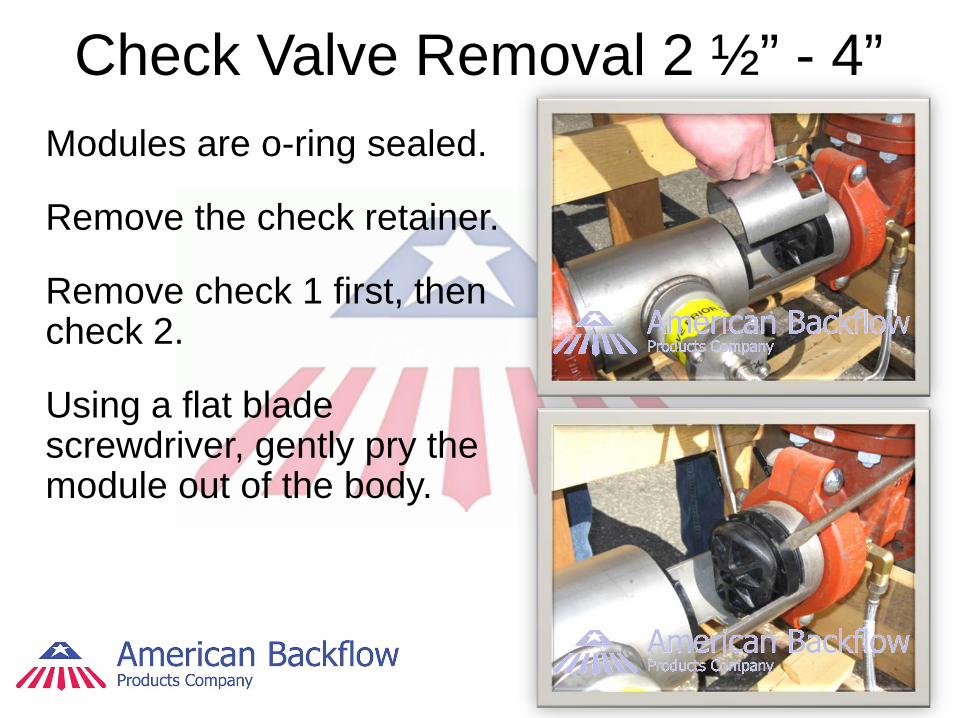
Check Valve Removal 2 ½” - 4” Modules are o-ring sealed.
Remove the check retainer.
Remove check 1 first, then check 2.
Using a flat blade screwdriver, gently pry the module out of the body.
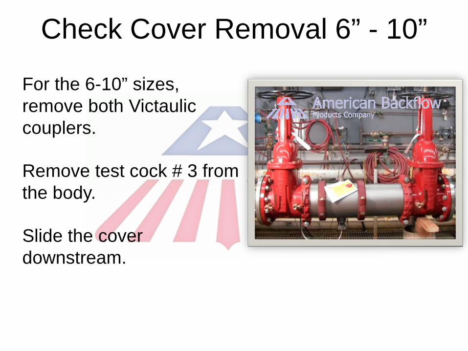
Check Cover Removal 6” - 10”
For the 6-10” sizes, remove both Victaulic couplers.
Remove test cock # 3 from the body.
Slide the cover downstream.

Check Valve Removal 6” - 10” Modules are o-ring
sealed.
Remove the 3 check retainers.
Remove check 1 first, then check 2.
Using a flat blade screwdriver, gently pry the module out of the body.
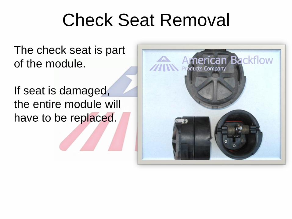
Check Seat Removal The check seat is part
of the module.
If seat is damaged, the entire module will have to be replaced.

Check Disc Replacement 2 ½” - 3” The check modules are
spring loaded.
Insert a screwdriver through the hole in the linkage and let it rest in the arbors on the module.
Remove the “E”-clip and pin connecting the linkage.
The clapper will open with no tension.

Check Disc Replacement 2 ½” - 3” Remove the screws
on the disc retainer.
Once disc is replaced, reassemble in reverse order.
Do not remove the spring assembly.

Check Disc Replacement 4” - 10” Locate the service hole on
the side of the check module.
Use a ½”-13 x 5 fully threaded bolt.
Thread the bolt until the hole in the linkage is aligned with the notches in the spring arbors.
Insert a long phillips screwdriver through the hole and arbors.
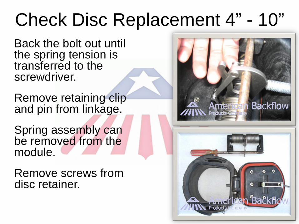
Check Disc Replacement 4” - 10” Back the bolt out until
the spring tension is transferred to the screwdriver.
Remove retaining clip and pin from linkage.
Spring assembly can be removed from the module.
Remove screws from disc retainer.

Check Valve Reassembly Notes
Reassemble check valves in reverse order.
Apply lubricant to o-rings.
Replace check 2 first, then check 1.
Relief Valve Removal
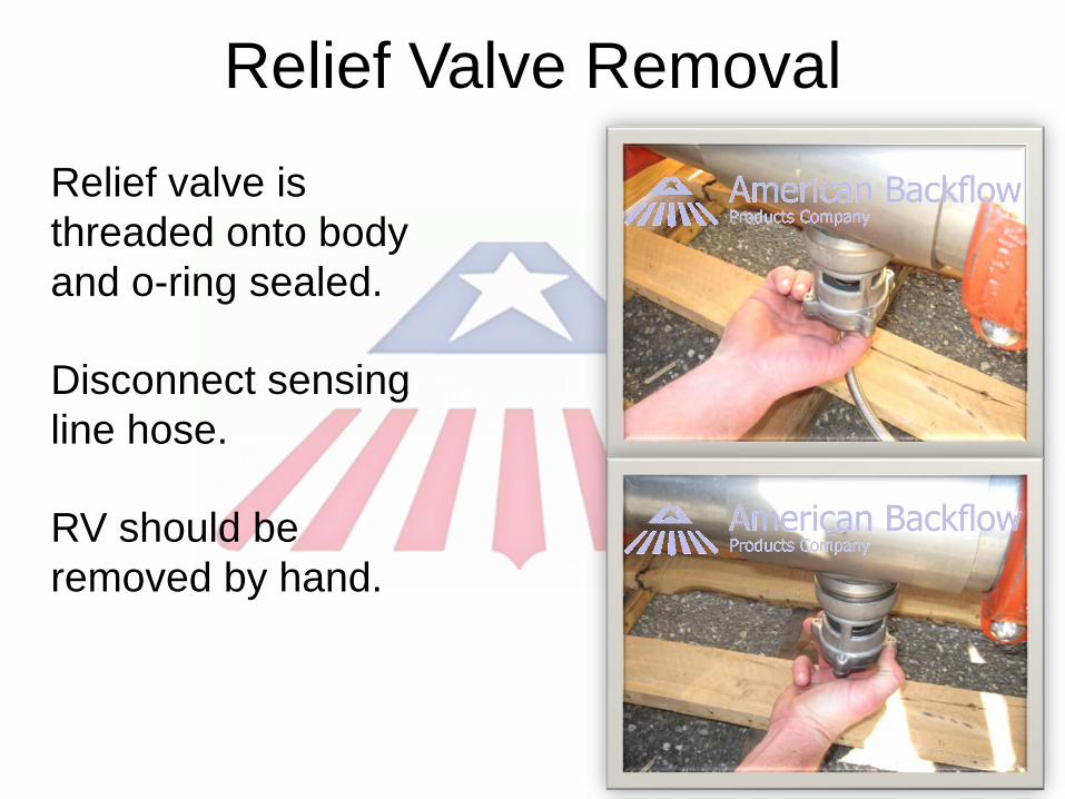
Relief valve is threaded onto body and o-ring sealed.
Disconnect sensing line hose.
RV should be removed by hand.
RV Disassembly
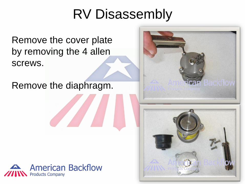
Remove the cover plate by removing the 4 allen screws.
Remove the diaphragm.

RV Disassembly With the threaded end
facing up, push up on the piston until the piston shaft with the attached E-clip is exposed.
Remove the E-clip.
RV Disc Replacement
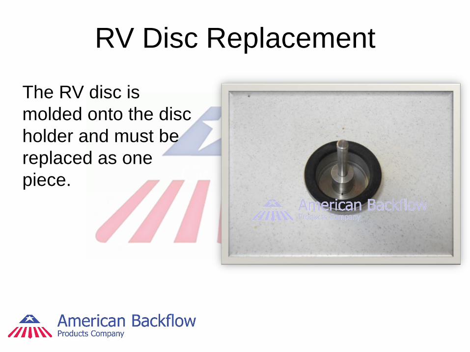
The RV disc is molded onto the disc holder and must be replaced as one piece.
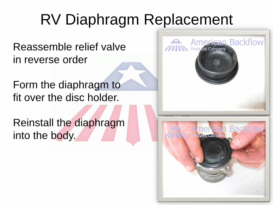
RV Diaphragm Replacement
Reassemble relief valve in reverse order
Form the diaphragm to fit over the disc holder.
Reinstall the diaphragm into the body.
RV Reassembly Notes
Lubricate the RV body o-ring.
Reattach the complete RV to the assembly body.


