54
M600 Mini-OTDR Optical Time Domain Reflectometer User’s Guide Test & Inspection

M600 Mini-OTDROptical Time Domain Reflectometer
User’s Guide
T e s t & I n s p e c t i o n

© 2002, AFL Telecommunications, all rights reserved. (For Software Version 2.4 or higher) M600-00-1000 Revision J, 8.12.05Specifications are subject to change without notice.
M600 Mini-OTDROptical Time Domain Reflectometer
User’s Guide
T e s t & I n s p e c t i o n
Limited Warranty
One Year Limited Warranty
All Noyes products are warranted against defective material and workmanship for a period of one year from the date of shipment to the original customer.
Any product found to be defective within the warranty period will be repaired or replaced by Noyes.
In no case will Noyes liabilities exceed the original purchase price of the product.
Exclusions
The warranty on your equipment shall not apply to defects resulting from the following:
• Unauthorized repair or modification
• Misuse, negligence, or accident
CE Information
These instruments have been designed and tested to comply with the relevant sections of any applicable specifications including full compliance with all essential requirements of all applicable EU Directives.
Returning Equipment
To return equipment, please contact Noyes to obtain additional information and a Service Request (S.R.) number. To allow us to serve you more efficiently, please include a brief description specifying the reasons for the return of the equipment.
AFL Telecommunications
Noyes Test & Inspection16 Eastgate Park RoadBelmont, NH 03220Tel: 800-321-5298 603-528-7780Fax: 603-528-2025

i
Table of Contents
Table of Contents
Safety InformationDefinitions of Warnings and Cautions .................................................................ivImportant Safety Information .............................................................................iv
Section 1: General InformationContacting Noyes Customer Service .................................................................1Unpacking and Inspection .................................................................................1Precautions ......................................................................................................1Recommended Accessories ..............................................................................2Feature Overview ..............................................................................................2
M600-VFI Option ..........................................................................................3
Section 2: Functional DescriptionFront Panel ......................................................................................................4Main Display ....................................................................................................6
Power-up Screen ..........................................................................................6Trace Screen ...............................................................................................6
Side Panels ......................................................................................................8Top Panel ........................................................................................................9
Section 3: Set up and OperationTo Switch on Power ..........................................................................................10Using M600 Menus .........................................................................................10
Display the Main Menu ..................................................................................10Select a sub-menu or parameter from a menu ................................................10Back — Return to the previous menu ...........................................................10Done — Close all menus ..............................................................................10
General Setup ...................................................................................................12View Events ..................................................................................................12Distance Units .............................................................................................12Time / Date ..................................................................................................12Reset Factory Defaults ..................................................................................12
Auto Setup .......................................................................................................12Test Mode .......................................................................................................12Test Setup ........................................................................................................13
Fiber Type .....................................................................................................13Wavelength (λ) ............................................................................................13Range and Resolution ...................................................................................14Pulse Width .................................................................................................14

ii
M600 User’s Guide
ii
Averages ......................................................................................................14Refractive Index ...........................................................................................15Thresholds ....................................................................................................16Backscatter Coefficient ................................................................................16
Starting and Stopping Tests (F1 key) .................................................................18Moving Cursors and Zooming ............................................................................18Selecting Loss Measurement Method .................................................................19Adjusting LSA Lines ..........................................................................................22Adding Events ...................................................................................................23
Adding Manual Events ...................................................................................23Adding Events Automatically .........................................................................24Viewing Events ..............................................................................................24Deleting Events .............................................................................................26
Saving Trace Files ............................................................................................27To Save a Trace File ......................................................................................27File Name Format .........................................................................................28To Enter/Change File Name ..........................................................................28To Enter/Change File Name Prefix ..................................................................28To Change Fiber Number ...............................................................................29To select directory and folder .........................................................................29To Create New Folders (Sub-folders) ..............................................................29To Edit A Text Field (cable ID, cable type, etc.) ................................................29
Working With Saved Traces ...............................................................................30To View a Trace .............................................................................................30To Compare Traces .......................................................................................30To Copy Traces and Folders ...........................................................................30To Delete Traces and Folders .........................................................................31
Printing Traces From a PC .................................................................................31
Section 4: Application Notes What You Will Need .........................................................................................32Before Using Your M600 ..................................................................................32Features of an OTDR Trace ...............................................................................33Fault Locating ..................................................................................................35
Section 5: MaintenanceRepair and Calibration ......................................................................................37Cleaning the Optical Ports ................................................................................37
To Clean an M600 Optical Port Connector ......................................................37To Clean a VFI Module Optical Port ................................................................37
Cleaning the Display and Case ...........................................................................38Battery Charging, Replacement, and Storage. .....................................................38
Charging .......................................................................................................38
iii
Table of Contents
Replacing .....................................................................................................39Storing .........................................................................................................39Disposing .....................................................................................................39
Section 6: SpecificationsM600 Optical Specifications ..............................................................................40M600 General Specifications ............................................................................40M600-VFI Specifications ...................................................................................41Available M600 Modules and Accessories ..........................................................41Fiber rings (FR) specifications ...........................................................................42Fiber boxes (FB) specifications ..........................................................................42
Appendix: ImageMate™ USB 2.0 Reader/WriterRemoving media ..............................................................................................42Disconnecting ...................................................................................................42
Definitions.........................................................................................................44
List of FiguresFigure 2-1: M600 Front Panel. ..........................................................................4Figure 2-2: M600 Trace Screen. .......................................................................7Figure 2-3: M600 Side Panels. .........................................................................8Figure 2-4: M600 Top Panel. ...........................................................................9Figure 3-1: M600 Menus. ................................................................................11Figure 3-2: Viewing Events in a Trace Format. ...................................................25Figure 3-3: Viewing Events in a Table Format. ...................................................25Figure 4-1: Example M600 Test Configuration With Launch And Receive Cables. 33Figure 4-2: M600 Trace Made Using Launch And Receive Cables. .....................34Figure 4-3: Using a Test Jumper to Fault-locate a Fiber Optic Link. .....................35Figure 4-4: M600 Trace Made Using A Test Jumper. .........................................35Figure 5-1: Charging a Battery Externally. .........................................................39Figure 5-2: Inserting a New Battery. .................................................................39

iv
M600 User’s Guide
A ! WARNING indicates a hazard. It calls attention to a procedure, practice, or the like, which if not performed correctly or adhered to, could result in injury or loss of life. Do not proceed beyond a WARNING until the indicated conditions are fully understood and met.
A ! CAUTION calls attention to an operating procedure, practice, or the like, which if not correctly performed or adhered to, could result in damage to or destruction of the M600 or other equipment or cause loss of stored test results. Do not proceed beyond a CAUTION sign until the indicated conditions are fully understood and met.
Important Safety Information
WARNING: Use of procedures or adjustments other than those specified herein may result in hazardous radiation exposure.
WARNING: Never look directly into the output of any optical fiber cable, jumper, or source. Refer to your company’s safety procedures when working with optical systems.
CAUTION: Do not run any tests or perform functions that activate an M600 laser unless fiber is attached to the corresponding OTDR port.
CAUTION: The M600 contains no user-serviceable parts. Do not open the case except to install OTDR modules, strictly following the instructions provided with the module.
CAUTION: If your M600 has a CompactFlash™ drive, a CompactFlash™ card must be installed before you turn power on, and must not be removed until after you turn power off.
Safety Information
The M600 OTDR is a CLASS I LASER PRODUCT
The M600 VFI is a CLASS II LASER PRODUCT.
Avoid exposure - Laser radiation is emitted from the M600-VFI aperture.WAVELENGTH: 650nmMAX. OUTPUT: 1.0mWPULSE RATE: 2 Hz, 50% DUTYCLASS II LASER PRODUCT
LASER RADIATIONDO NOT STARE INTO BEAM
CAUTIONLASER RADIATIONDO NOT STARE INTO BEAMCLASS 2 LASER PRODUCTWAVELENGTH: 650nmMAX OUTPUT: 1.0mwPULSE RATE: 2Hz, 50% DUTYIEC825-1: 1993, EN60825-1: 1994
Definitions of Warnings and Cautions
!
!
!
!
!
1
Section 1
Section 1: General InformationThank you for purchasing a Noyes M600 Mini-OTDR. The purpose of this User’s Guide is to explain how to use and maintain your new M600. Please check our web site at www.AFLtele.com (click on Products > Test & Inspection) for updates to this manual, software updates, and additional application information. If you have any questions about your M600 or recommended accessories, please contact Noyes Customer Service.
Contacting Noyes Customer Service You may call Noyes Customer Service between 8 a.m. and 5 p.m., United States Eastern Time, as follows:
Tel: 800-321-5298 (North America) 603-528-7780Fax: 603-528-2025Web: www.AFLtele.com (click on Products > Test & Inspection)
Unpacking and InspectionThis instrument has been carefully packed in accordance with standard shipping procedures. Examine the equipment for damage that may have occurred during shipment. If you find any damage, or if any of the following items are not included, please contact Noyes.
• M600 OTDR with ordered modules
• Carry case with strap
• AC power adapter and cord
• Keyboard
• Trace analysis software and user’s guide
• CompactFlash™ card
• CompactFlash™ reader (USB)
• User’s guide
PrecautionsProper care in handling should be taken when using any precision optical test equipment, such as the M600. Scratched or contaminated optical connectors can impact the performance of your M600. It is important to keep the optical ports on your M600, as well as the optical connectors on all test cables and jumpers used with your M600, free from dirt, oils, or other contaminants. Always replace protective dust caps. Proper cleaning techniques should be performed on all test cables and jumpers before conducting the test procedures outlined in this manual. In addition, the optical ports of your M600 should be cleaned periodically. Please see “Cleaning the Optical Ports” for more information. the optical ports of your M600 should be cleaned periodically. Please see “Cleaning the Optical Ports” for more information.

2
M600 User’s Guide
Recommended Accessories You will need fiber optic test cables (or jumpers) to connect your M600 to the fiber under test. Test cables must have the same core and cladding size as the fiber under test. The connector at one end of the test cable must mate with the appropriate optical port on the M600. The connector on the other end must mate with the fiber optic link under test. Test cables and jumpers with a variety of lengths and connector styles are available from Noyes.
Fiber Boxes may be used as launch and receive cables, which are required to measure the insertion loss and reflectance of the near-end and far-end connectors respectively, on the fiber link being tested. Fiber Boxes with a variety of lengths and connector styles are available from Noyes.
A supply of optical cleaning pads and isopropyl alcohol or a connector-cleaning cartridge is recommended to clean the optical connectors on your M600 and test cables. A supply of fiber optic cleaning swabs or a can of filtered compressed air is recommended for cleaning connector adapters.
Feature OverviewDesigned to accept multimode and single-mode modules, the M600 mini-OTDR may be used to test and fault-locate fiber optic cables in premises, access, and long-distance network applications. The M600 offers automatic and manual setup modes to meet the needs of both novice and experienced users.
The M600 OTDR or “optical time domain reflectometer” tests an optical fiber link, while having access to only one end of the link, by generating short pulses of light, sampling reflected light as a function of time, and converting these samples into a graph or “trace” of insertion loss versus distance. Based on the shape of the trace the M600 can locate and analyze fiber link “events” such as connections, splices, bends, and breaks.
All M600 models are equipped with CompactFlash™ drive and memory card capable of storing up to 1,500 traces.
Note: An M600 only works with the CompactFlash™ card installed.
Also, traces can be saved to internal non-volatile memory (300 traces) or floppy disk ( 50 traces). Noyes recommends saving traces to the CompactFlash™ memory card. A floppy drive may be used to transfer a “few” (< 50) traces to or from a PC, and to download new M600 software.
Using the supplied CompactFlash™ reader (USB) or floppy disk, saved traces can be transferred to a PC for archiving, printing, and analyzing with the supplied Trace600 Windows® software.

3
Section 1
WAVELENGTH: 650nmMAX. OUTPUT: 1.0mWPULSE RATE: 2 Hz, 50% DUTYCLASS II LASER PRODUCT
LASER RADIATIONDO NOT STARE INTO BEAM
CAUTION
LASER RADIATIONDO NOT STARE INTO BEAMCLASS 2 LASER PRODUCTWAVELENGTH: 650nmMAX OUTPUT: 1.0mwPULSE RATE: 2Hz, 50% DUTYIEC825-1: 1993, EN60825-1: 1994
M600 -VFI Module. Top View.
Push Button Switch Laser Output
ON/ 2Hz / OFF
AVOID EXPOSURE-LASER RADIATION IS EMITTED FROM THIS APERTURE
M600-VFI Option
The M600 OTDR may be equipped with a Visible Fault Identifier (VFI) module. The VFI module is a 650 nm visible red laser source designed to troubleshoot faults on fiber optic cables.
Light generated by the VFI module will escape from sharp bends and breaks in jacketed or bare fibers, as well as poorly mated connectors. Thus, the VFI can identify faults in fiber optic jumper cables, distribution frames, patch panels, and splice trays.
The VFI module is an excellent compliment to an OTDR because it can locate faults inside the OTDR’s dead-zone. Other applications include end-to-end continuity checks, identifying connectors in patch panels, and identifying fibers during splicing operations.
The universal connector interface provides fast operation with many connector styles without changing an adapter.
The M600-VFI operates off the M600 power supply. The M600 must be turned ON before operating the M600-VFI.
The M600-VFI is switched ON/OFF by the momentary push button switch located on the M600-VFI module. The switch modes are: ON/ 2Hz/ OFF.
Pressing the switch once turns the module ON. The red LED inside the lighted switch turns ON, and the module transmits laser radiation at 650 nm, Continuous Wave. Pressing the switch again places the module in 2 Hz mode. The LED inside the switch blinks ON/OFF and the module transmits laser radiation at a modulated rate of 2 Hz, 50% duty cycle. Pressing the switch again turns the module OFF.
The M600 VFI is a CLASS II LASER PRODUCT.
4
M600 User’s Guide
AFL TelecommunicationsNOYES
λλ
Power
M600 Optical Time Domain Reflectometer
AC Adapter Save Help
F5F4F3F2F1
Laser
2
1
3
6
10
11
7 8 954
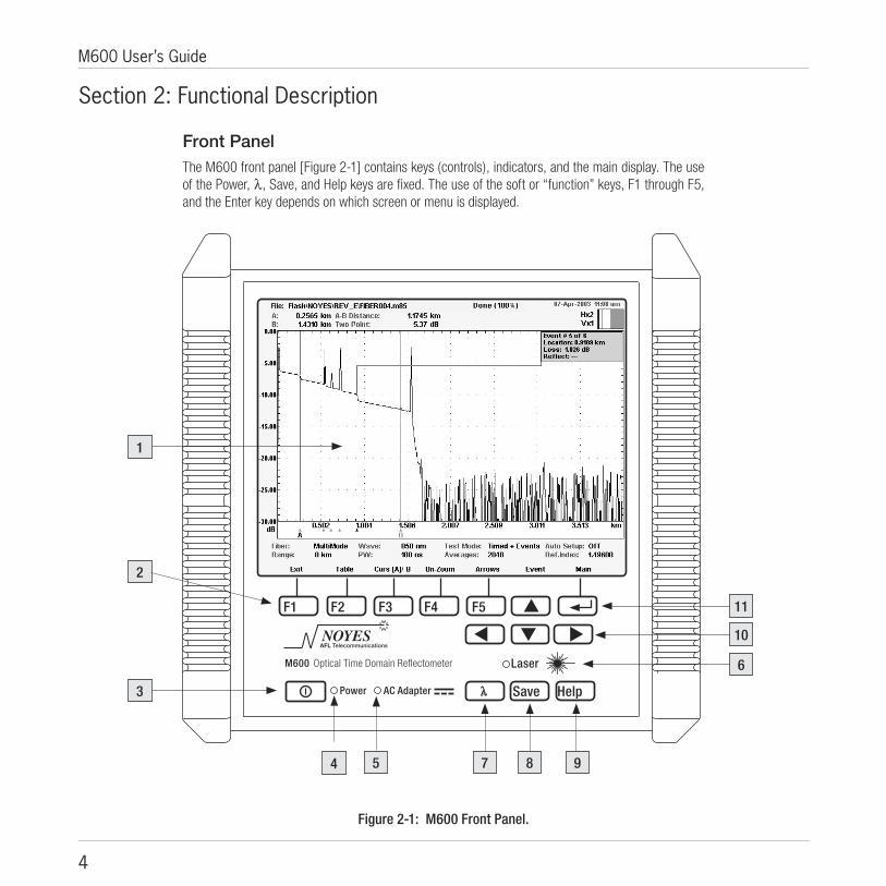
Figure 2-1: M600 Front Panel.
Section 2: Functional Description
Front Panel The M600 front panel [Figure 2-1] contains keys (controls), indicators, and the main display. The use of the Power, λ, Save, and Help keys are fixed. The use of the soft or “function” keys, F1 through F5, and the Enter key depends on which screen or menu is displayed.

5
Section 2
The M600 front panel features are explained below:
# Front panel feature Description
1 Main Display Used to show the OTDR trace screen, setup menus, and file management screens.
2 Function keys (F1 – F5) The label shown on the main display above each key indicates the current use of each function key.
3 Power key Press and hold for about 2 seconds to turn the M600 on or off.
4 Power indicator When on, indicates that the M600 is switched on and powered either by the internal battery or AC adapter.
5 AC Adapter indicator When on, indicates that a live AC adapter is connected to the M600.
6 Laser active indicator When on, indicates that a test is in progress and an optical port is active.
7 λ (Wavelength) key Press to change the test wavelength.
8 Save key Press to save and name the displayed trace.
9 Help key Press to display a help page with useful tips and Noyes contact information.
10 Arrow keys Press to navigate menus, change setup parameters, move cursors, and change the zoom level.
11 Enter key Press to display the Main Menu or to select items in menus.
6
M600 User’s Guide
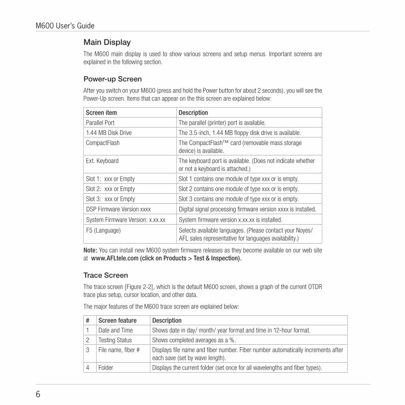
Main Display The M600 main display is used to show various screens and setup menus. Important screens are explained in the following section.
Power-up Screen
After you switch on your M600 (press and hold the Power button for about 2 seconds), you will see the Power-Up screen. Items that can appear on the this screen are explained below:
Screen item Description
Parallel Port The parallel (printer) port is available.
1.44 MB Disk Drive The 3.5-inch, 1.44 MB floppy disk drive is available.
CompactFlash The CompactFlash™ card (removable mass storage device) is available.
Ext. Keyboard The keyboard port is available. (Does not indicate whether or not a keyboard is attached.)
Slot 1: xxx or Empty Slot 1 contains one module of type xxx or is empty.
Slot 2: xxx or Empty Slot 2 contains one module of type xxx or is empty.
Slot 3: xxx or Empty Slot 3 contains one module of type xxx or is empty.
DSP Firmware Version xxxx Digital signal processing firmware version xxxx is installed.
System Firmware Version: x.xx.xx System firmware version x.xx.xx is installed.
F5 (Language) Selects available languages. (Please contact your Noyes/AFL sales representative for languages availability.)
Note: You can install new M600 system firmware releases as they become available on our web site at www.AFLtele.com (click on Products > Test & Inspection).
Trace Screen
The trace screen [Figure 2-2], which is the default M600 screen, shows a graph of the current OTDR trace plus setup, cursor location, and other data.
The major features of the M600 trace screen are explained below:
# Screen feature Description
1 Date and Time Shows date in day/ month/ year format and time in 12-hour format.
2 Testing Status Shows completed averages as a %.
3 File name, fiber # Displays file name and fiber number. Fiber number automatically increments after each save (set by wave length).
4 Folder Displays the current folder (set once for all wavelengths and fiber types).

7
Section 2
Figure 2-2: M600 Trace Screen.
6
7
8
5
10
11
9
4 23 1
5 Cursor data Shows the locations of cursors A and B, distance from A to B, and loss based on selected loss Method.
6 Trace This is a graph of insertion loss vs. distance. The vertical axis shows loss in dB. The horizontal axis shows distance in user-selected units.
7 Cursors A and B Used to measure loss, reflectance, and distance. They can be moved using the Left and Right arrow keys.
8 Unit setup Shows Fiber Type, Range, Wavelength, PW (pulse width), Test Mode, Averages, Auto Setup (on or off), and Ref. Index (refractive index).
9 Function key labels Shows the current use of each function key.
10 Events Data Displays Event #, location, loss, and reflectance. Event locations are marked using “ “ icons under the distance axis.
11 Zoom Bar In the zoom mode, shows the size of the current view and the location of the cursors relative to the entire trace.

8
M600 User’s Guide
18V 2.2A
KeyboardNot Used
ParallelContrast
Power
+−
Disk
ette
Driv
e
Batte
ry
1
2
4
6
5
8
7
Left Side Right Side
3
Side PanelsThe M600’s side panels contain a floppy disk drive, CompactFlash™ drive, display contrast control, battery access door, and interface ports for a PS/2 keyboard, parallel printer, and AC adapter.
The M600 side panel features are identified below [Figure 2-3]:
# Panel feature Description
1 Keyboard port Interface for a PS/2 type keyboard.
2 (Not Used) This port is not used in the current M600 design.
3 CompactFlash™ drive Insert a CompactFlash™ card here.
4 Parallel port Not used at this time.
5 Contrast control Adjusts contrast.
6 Power port DC power input (18 V, 2.2 A). This is the interface for the M600 AC power adapter.
7 Battery door Provides access to the rechargeable battery.
8 Floppy Disk Drive 3.5-inch, 1.44 MB floppy disk drive.
Figure 2-3: M600 Side Panels.

9
Section 2
ON/ 2Hz / OFF
AVOID EXPOSURE-LASER RADIATION IS EMITTED FROM THIS APERTURE
Figure 2-4: M600 Top Panel.
31 2
Top Panel Depending on which modules are installed, the top panel of your M600 may have one or two optical ports. In a quad-wavelength M600 the 850/1300 nm multimode module is normally installed in Slot 1 while the 1310/1550 nm single-mode module is normally installed in Slot 2.
The M600 top panel contains the following features [Figure 2-4]:
# Feature Description
1 Port 1 Normally the 850/1300 nm multimode OTDR port.
This is a CLASS I LASER output.
2 Port 2 Normally the 1310/1550 nm single-mode OTDR port.
This is a CLASS I LASER output.
3 Port 3 May be equipped with an M600-VFI module, 650 nm Visible Fault Identifier.
LASER RADIATIONDO NOT STARE INTO BEAMCLASS 2 LASER PRODUCTWAVELENGTH: 650nmMAX OUTPUT: 1.0mwPULSE RATE: 2Hz, 50% DUTYIEC825-1: 1993, EN60825-1: 1994
This is a CLASS II LASER output.

10
M600 User’s Guide
!
Section 3: Set up and OperationThe following section explains how to set up and operate your M600.
CAUTION To ensure proper operation, a CompactFlash™ card must be inserted before the M600 is powered up and should not be removed until the instrument is powered off.
To Switch on Power1 Press the Power key for about 2 seconds. The unit will go through a self-test and then display the
Power-Up screen. If the M600 does not switch on, verify that the battery is charged, or that an AC power adapter is connected to the M600 and plugged into a live power outlet.
2 Press the Enter key to view the OTDR trace screen.
Using M600 Menus M600 menus [Figure 3-1] are used for most setup functions. To display the Main Menu, press the Enter key. To select a sub-menu or parameter in an M600 menu, use the arrow keys to “highlight” the item (move the selection box around the item), then press the Enter key again. Most M600 menus contain Back and Done selections. Selecting Back will display the previous menu. Selecting Done will cause the M600 to exit all menus and display the trace screen.
Display the Main Menu
• Press the Enter key.
Select a sub-menu or parameter from a menu
• Use the arrow keys to highlight the desired sub-menu or parameter.
• Press the Enter key.
Back — Return to the previous menu
• Use the arrow keys to highlight Back.
• Press the Enter key.
Done — Close all menus
• Use the arrow keys to highlight Done.
• Press the Enter key.

11
Section 3
Wavelength 850 or 1300 nm (multimode) 1310 or 1550 nm (single-mode)
Fiber Type Multimode or single-mode
Range/Res. Trace distance range and point spacing
Main Menu
Test Setup
Pulse Width Which pulse widths are available depends on Fiber Type and Wavelength
Averages Number of averages in timed tests
Refractive Index Group Index of Refraction, 1.4000 – 1.7000
Backscatter Backscatter Coefficient Used to calculate event reflectance
Distance Units kilometers, meters, miles, feet
Auto Setup Automatic pulse width and range set up, On, Once, or Off
Test Mode Live: 256 averages (repeated) Timed: 2048 to 65,536 averages (one-time) Auto Events: Same as Timed plus automatic event table generation
Saved Files Open saved files (F2) Select All (F3) Select None (F4) Select (F5) File Menu (Menu key): Copy/ Delete files and create New Folders
Figure 3-1: M600 Menus.
View Events View events in Trace View
Add Events Add reflective, non-reflective, multiple, and automatic events (type depends on loss method)
Thresholds Fiber End Event Loss Reflectance
Loss Method Select loss measurement method
Adjust LSA Lines Adjust LSA lines boundaries (if applicable)
Time/Date Hr : min day - month - year
General Setup
Reset Factory Defaults
System Information Display the Power-up screen

12
M600 User’s Guide
General Setup
View Events
1 Select Main (press Enter) > General Setup > Enter > View Events.
2 If you prefer to view events in the trace view, choose Yes.
Distance Units
1 Select Main (press Enter) > General Setup > Enter > Distance Units.
2 Select the desired units of measure (kilometers, meters, miles, or feet).
Time / Date
1 Select Main (press Enter) > General Setup > Enter > Time / Date.
2 Use the arrow keys to edit time (hours: minutes) and date (day/ month/ year).
Reset Factory Defaults
1 Select Main (press Enter) > General Setup > Enter > Reset Factory Defaults.
2 When prompted to verify resetting, choose OK or Cancel.
Auto SetupWhen Auto Setup is on, the M600 determines the length of the fiber optic link under test and then automatically sets Range/Resolution and Pulse Width. When Auto Setup is off, you must set these two parameters manually.
1 Select Main (press Enter) > Auto Setup > Enter.
2 Choose On, Once, or Off.
Test Mode The M600 can perform Live, Timed, or Auto Event tests. In a live test, the M600 continuously collects and averages 256 samples (for each trace data point) and updates the trace display in near real time. In a timed test, the M600 collects and averages samples a user-specified number of times and then stops collecting new samples. The trace display is updated during a timed test, so you can see the smoothing effect of averaging. In an Auto Event test, the M600 performs a timed test and then automatically creates an event table based on the current set thresholds. To select Test Mode:
1 Select Main (press Enter) > Test Mode > Enter.
2 Choose Live, Timed, or Auto Events.

13
Section 3
Test SetupThe table below gives a summary of OTDR parameters and how they are set. Parameter scope indicates whether a parameter is set separately (for each wavelength or for each fiber type) or globally (once for all wavelengths and fiber types). The scope of each parameter will be listed as “By Wavelength”, “By Fiber Type”, or “Global”.
Setup Parameters ScopeFiber Type Global
Wavelength Fiber Type
Range/Resolution Fiber Type
Pulse width Wavelength
Averages Wavelength
Refractive Index Wavelength
Thresholds Wavelength
Backscatter Wavelength
Setup Parameters ScopeDistance Units Global
Current time/date Global
Directory Global
Filename Prefix Fiber Type
Fiber Number Wavelength
Cable ID Fiber Type
Timed / Live Global
Auto Setup (On or Off) Global
Fiber Type
Fiber Type determines the active module and therefore the type of fiber (multimode or single-mode) you can test. For example, in an M600 equipped with M600-MM1 and M600-SM1 modules, selecting multimode will make the M600-MM1 module active, while selecting single-mode will make the M600-SM1 module active. To set fiber type:
1 Select Main (press Enter) > Test Setup > Enter > Fiber Type > Enter.
2 Choose either Multimode or Single-mode
Wavelength (λ)
The Wavelength parameter determines which laser is used to generate the OTDR trace and therefore sets the nominal test wavelength. To set a wavelength, do one of the following:
1 From the front panel, press the [λ] key
or:
1 Select Main (press Enter) > Test Setup > Enter > Wavelength > Enter.
2 Choose a wavelength:
• 850 or 1300 nm for the M600-MM1 multimode module
• 1310 or 1550 nm for the M600-SM1 single-mode module
14
M600 User’s Guide
Note: Because Fiber Type determines which Wavelengths are available, select Fiber Type before selecting Wavelength.
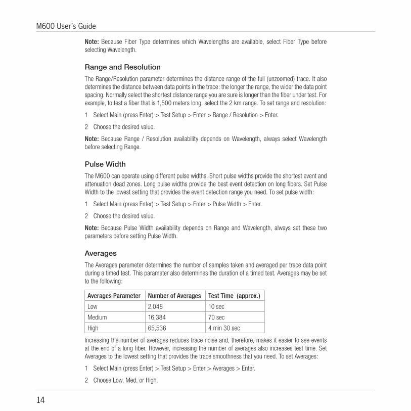
Range and Resolution
The Range/Resolution parameter determines the distance range of the full (unzoomed) trace. It also determines the distance between data points in the trace: the longer the range, the wider the data point spacing. Normally select the shortest distance range you are sure is longer than the fiber under test. For example, to test a fiber that is 1,500 meters long, select the 2 km range. To set range and resolution:
1 Select Main (press Enter) > Test Setup > Enter > Range / Resolution > Enter.
2 Choose the desired value.
Note: Because Range / Resolution availability depends on Wavelength, always select Wavelength before selecting Range.
Pulse Width
The M600 can operate using different pulse widths. Short pulse widths provide the shortest event and attenuation dead zones. Long pulse widths provide the best event detection on long fibers. Set Pulse Width to the lowest setting that provides the event detection range you need. To set pulse width:
1 Select Main (press Enter) > Test Setup > Enter > Pulse Width > Enter.
2 Choose the desired value.
Note: Because Pulse Width availability depends on Range and Wavelength, always set these two parameters before setting Pulse Width.
Averages
The Averages parameter determines the number of samples taken and averaged per trace data point during a timed test. This parameter also determines the duration of a timed test. Averages may be set to the following:
Averages Parameter Number of Averages Test Time (approx.)
Low 2,048 10 sec
Medium 16,384 70 sec
High 65,536 4 min 30 sec
Increasing the number of averages reduces trace noise and, therefore, makes it easier to see events at the end of a long fiber. However, increasing the number of averages also increases test time. Set Averages to the lowest setting that provides the trace smoothness that you need. To set Averages:
1 Select Main (press Enter) > Test Setup > Enter > Averages > Enter.
2 Choose Low, Med, or High.

15
Section 3
Refractive Index
The refractive index of an optical fiber, also known as its Group Index of Refraction or GIR, determines the speed of light in the fiber. Refractive index is used by the M600 to determine cursor and event distances. When setting Refractive Index, enter the value specified by the manufacturer of the fiber optic cable you are testing. To set refractive index:
1 Select Main (press Enter) > Test Setup > Enter > Refractive Index > Enter.
2 Set the refractive index. Use Arrow keys to navigate to the desired digit and to increase/decrease its value.
Note: If you don't know the refractive index values of the fiber you are testing, use the following:
Multimode Single-mode
850 nm: 1.496 1310 nm: 1.4675
1300 nm: 1.487 1550 nm: 1.4681
These values are within 1% of the values specified for most fiber optic cables. If you later learn the exact values specified by the cable manufacturer, you can correct the refractive index values in the stored M600 trace file.

16
M600 User’s Guide
Thresholds
M600 thresholds are used to generate event tables automatically, either at the end of an Auto Events test or when you select “Automatic” from the Add Events menu. The three M600 automatic event table thresholds are defined below:
Threshold Definition Default value
End Loss (dB) Used to determine the location of the “fiber end” which may be a break in the fiber under test, the end of the fiber under test, or the end of a receive cable (if one is used)
6.0 dB
Event Loss (dB) Used to add automatic events by insertion loss 0.01 dB
Event Reflection (dB) Used to add automatic events by reflectance -65 dB
In an automatically generated event table, events that are not end events (Reflective, Non-Reflective, or Multiple) will be included if they exceed either the Event Loss, Reflectance, or both thresholds. End events (Reflective End, Non-Reflective End) will be included if their insertion loss exceeds the Fiber End threshold. The “Source” of events added automatically to event tables will be shown as “Auto”. After an event table has been generated automatically, you can delete or add comments to Auto events, and you can add or delete Manual events.
Backscatter Coefficient
The backscatter coefficient is used to calculate a reflectance value. Backscatter coefficient values are specified by the manufacturer of the fiber optic cable. To set Backscatter Coefficient:
1 Select Main (press Enter) > Test Setup > Enter > Backscatter > Enter.
2 Set the backscatter coefficient.
If the backscatter coefficient is not specified by the fiber manufacturer, use the default values.
Note: If you later learn the exact values specified by the manufacturer, you can correct the Backscatter Coefficient values in the stored M600 trace file.
Wavelength Backscatter Coefficient
850 nm 68.00
1300 nm 76.00
1310 nm 80.00
1550 nm 83.00

17
Section 3

18
M600 User’s Guide
Starting and Stopping Tests (F1 key) You can start or stop tests by pressing the F1 key (front panel or keyboard). When no test is running, the F1 key will be labeled [Test], which means you can press F1 to start a new test. When a test is running, the F1 key will be labeled [Stop], which means you can press F1 to stop the current test.
Moving Cursors and ZoomingThe A and B cursors may be positioned to measure the distance and loss between any two points on a trace. To make cursor positioning easier and to see fine details in the trace, you can zoom (expand) the trace graph in the horizontal or vertical direction. Cursor movement and zoom are controlled using the arrow keys and function keys F3 - F5.
Moving Cursors
Key Label Function
F3 “Curs A/[B]”Brackets indicate the active cursor
Press to toggle between cursors
Press to move the active cursor to the rightPress and hold for fast movement
Press to move the active cursor to the leftPress and hold for fast movement
Zooming
“Zoom [H]/V”Brackets indicate the active zoom mode
Press to zoom-in (increase magnification)
“Zoom [H]/V”Brackets indicate the active zoom mode
Press to zoom-out (decrease magnification)
F5 “Arrows” Press to cycle the / arrow keys function through available options: horizontal zoom mode, vertical zoom mode, and selecting events option.
F4 “ - ” (blank)“Un-Zoom”“Re-Zoom”
Not used in the default un-zoomed viewPress to display the un-zoomed viewPress to display the previous zoomed view
In zoomed view, the M600 always displays the active cursor area. If you need to un-zoom, move the active cursor, and then re-zoom, the M600 will display the new position of the active cursor at the previous zoom level.

19
Section 3
Selecting Loss Measurement MethodFor analyzing traces and adding events manually, the M600 offers various Loss Measurement Methods.
The table below gives a summary of the available Loss Measurement Methods.
Loss Method (and Applications)
Measured Parameters No. of Cursors
No. of LSA Lines
LSA Lines Adjustment
Event Type(s) Allowed
Two Point(General purpose)
Location, Reflectance, Insertion loss between any 2 points of a trace
2 0 Reflective,Non-Refl.,Multiple
Single Event(Connections, splices, faults)
Location, Reflectance, Insertion loss of any Reflective or Non-Refl.event
1 2 Far LeftNear LeftNear RightFar Right
Reflective,Non-Refl.
Multiple Event(2 or more events close together)
Location and Insertion loss of multiple events
2 2 Far LeftNear LeftNear RightFar Right
Multiple
Fiber Attenuation(Use to measure fiber loss in dB/km)
Attenuation per loss ratio of any segment of a trace with no events
2 1 Not used toadd events
Start(If no Launch Cable)
Trace level at the Near-end connection
1 1 Near RightFar Right
Start
End(If no Receive Cable)
Location, Reflectance, and Trace level at the Far-end connection
2 1 Far LeftNear left
Reflective End,Non-Refl. End
*LSA Line -least squared approximation segment line. Used to reduce the effects of noise while calculating insertion loss, trace level, and attenuation.
To select the Loss Method:
1 Select Main (press Enter) > Loss Method > Enter to display a list of available Loss Methods.
2 Use arrow keys to choose the desired method.
3 Choose Done > Enter to enable the selected Loss Method.
Depending on the selected Loss Method, you will need to position cursors and adjust LSA lines (if applicable) properly.
The following graphs illustrate position of cursors and LSA lines for the available Loss Measurement Methods.

20
M600 User’s Guide
Left cursor Right cursor
Left LSA line Right LSA line
Cursor Near Right boundary
Left LSA line Right LSA line
Near Right boundary
Right CursorLeft Cursor
Multiple Event Loss Measurement Method
1 Position the left cursor at the start of the first event.
2 Position the right cursor at the start of the last event.
3 If required, adjust right LSA line so the Near Right boundary located beyond the event where the trace returns to a constant slope.
4 Read the insertion loss measurement.
Or
4 Select Main (press Enter) > Add Events > Enter to save and display the event data.
Two Point Loss Measurement Method
1 Position the left cursor at the start of the event.
2 Position the right cursor beyond the event where the trace returns to a constant slope.
3 Read the insertion loss measurement.
Or
4 Select Main (press Enter) > Add Events > Enter to save and display the event data.
Single Event Loss Measurement Method
1 Position a cursor at the start of the event.
2 If required, adjust right LSA line so the Near Right boundary located beyond the event where the trace returns to a constant slope.
3 Read the insertion loss measurement.
Or
4 Select Main (press Enter) > Add Events > Enter to save and display the event data.
21
Section 3
Left cursor Right cursor
Cursor
Near Right boundaryRight LSA line
Left LSA line
Right CursorLeft Cursor
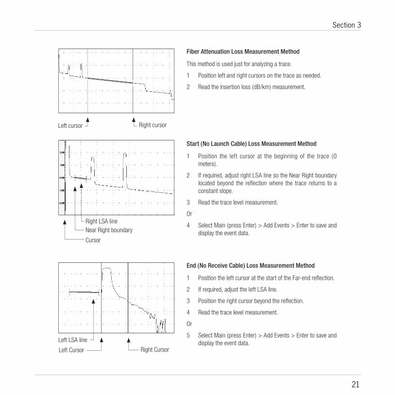
Fiber Attenuation Loss Measurement Method
This method is used just for analyzing a trace.
1 Position left and right cursors on the trace as needed.
2 Read the insertion loss (dB/km) measurement.
Start (No Launch Cable) Loss Measurement Method
1 Position the left cursor at the beginning of the trace (0 meters).
2 If required, adjust right LSA line so the Near Right boundary located beyond the reflection where the trace returns to a constant slope.
3 Read the trace level measurement.
Or
4 Select Main (press Enter) > Add Events > Enter to save and display the event data.
End (No Receive Cable) Loss Measurement Method
1 Position the left cursor at the start of the Far-end reflection.
2 If required, adjust the left LSA line.
3 Position the right cursor beyond the reflection.
4 Read the trace level measurement.
Or
5 Select Main (press Enter) > Add Events > Enter to save and display the event data.

22
M600 User’s Guide
Adjusting LSA LinesIf events of a trace are located very close to each other, you may have to adjust the LSA Lines. The graphs below illustrate an example of the LSA Line before and after the adjustment.
To adjust LSA lines:
1 To enable the LSA adjustment mode, Select Main (press Enter) > Adjust LSA Lines > Enter.
2 Press F3 (LSA Adjust) to display the LSA Adjust Menu.
• Use arrow keys to select the desired LSA line boundary.
• Press Enter to confirm your selection.
3 Use the / arrow keys to decrease/increase the LSA line length as needed.
4 When the adjustment is complete, Select Main (press Enter) > Exit LSA Adjust > Enter.
F3
LSA Adjust Menu
Far Left BoundaryDashed line indicates that this boundary is not selected for the adjustment
Near Left Boundary
Far Right BoundarySolid line indicates that this boundary is selected for the adjustment
Near Right Boundary
LSA Line before the adjustment LSA Line after the adjustment
Press to display the LSA Adjust Menu

23
Section 3
Active cursor
Event mark
Event data boxTo turn the Event data box ON/OFF, press Enter > Test Setup, then using arrow keys navigate to Viewing Options, and then check Events > Yes /No
Line indicates the Event location
Adding Events
Adding Manual Events
The M600 allows you to add manual events to the current event table. Based on the selected Loss Measurement Method, the M600 allows you to choose the event type as follows:
Selected Loss Method Event Type(s) Allowed
Two Point Reflective, Non-Refl., Multiple
Single Event Reflective, Non-Refl.
Multiple Event Multiple
Start (No Launch Cable) Start
End (No Receive Cable) Reflective End, Non-Refl. End
To add an event manually:
1 Select loss method, then set cursors and LSA segments as required to measure the event.
2 Select Main (press Enter) > Add Events > Enter to display a list of the allowed event types for current loss method.
3 Using arrow keys choose the desired event type.
4 Press Enter to add the event.
Note: Based on the location of the left cursor, M600 places the event mark in the Trace Display window and automatically adds the event to the Event Table. The events in the Event Table are ordered
by increasing location.
5 You may press F2 (Table) to view data added to the event table.

24
M600 User’s Guide
6 If you need to add a comment:
a) Press F4 (Comment) to activate first line in the comment field.
b) Press Menu (Edit) enable the editing mode and display a table of characters.
c) If you are using a keyboard, type the comment (up to 30 char.), then press Enter.
d) If you are using the Front Panel keys:
• Use the arrow keys to highlight the desired character.
• Press F5 (Char) to enter the selected character.
• Repeat the above two steps to enter up to 30 char.
• You may press F4 (Bksp) to delete the last character.
• Press Menu (OK) to save the current entry and exit the editing mode.
e) If you need to use 2nd and 3rd lines for comments, highlight the line, then repeat steps (b) - (d).
7 Press F2 (Trace) to return to the Graph window.
Adding Events Automatically
From the Add Events menu you can create an automatic event table by selecting “Automatic”. This function deletes all events from the current event table, whether they were generated manually or automatically, and then creates a new event table based on current Threshold settings.
Viewing Events
Events may be viewed in either trace graph or table format. Both formats allows you to identify the following trace data:
• Location in user selected units (m, ft, km, mi)
• Insertion Loss (dB)
• Reflectance (dB)
In addition, the Event Table provides the following information:
• Event type• Lead-in fiber attenuation (dB/km)• Cumulative Insertion Loss (dB)
To view events:
1 Press F2 (Table) to display the Event Table.
2 Use the / arrow keys to select the desired event.
3 To view the selected event in the graph format, press F2 (Trace).

25
Section 3
F5F4F3F2F1
F5F4F3F2F1
Event data box shows:Location, Insertion Loss, Reflectance
Event mark of the currently selected event
Line indicates the selected event
Press to view the event table
Press to delete an event
Note: End events will not show insertion loss measurements.
Cumulative insertion loss from the first eventInsertion loss of the selected event in dB
Lead-in fiber attenuation of a fiber before the selected event (dB/km)
Note: End events will not show insertion loss (Ins. L)
Event Type
Event location in current distance units
Reflectance of the selected event in dB
Press to view the Trace
Press to add comments
Comments field
Figure 3-2: Viewing Events in a Trace Format.
Figure 3-3: Viewing Events in a Table Format.

26
M600 User’s Guide
Note: In the Event Table you can add or edit an existing comment.
To add/edit comments:
1 Highlight the desired event.
2 Press F4 (Comment) to activate first line in the comment field.
3 Press Menu (Edit) to enable the editing mode and display a table of characters.
4 Edit / enter a comment.
a) If you are using a keyboard, type the comment (up to 30 char.), then press Enter.
b) If you are using the Front Panel keys:
• Use the arrow keys to highlight the desired character.
• Press F5 (Char) to enter the selected character.
• Repeat the above two steps to enter up to 30 char.
• You may press F4 (Bksp) to delete the last character.
• Press Menu (OK) to save the current entry and exit the editing mode.
5 If you need to use 2nd and 3rd lines for comments, highlight the line, then repeat steps 3 & 4.
6 Press F2 (Trace) to return to the Graph window or F4 to select events.
Deleting Events
To delete an event:
1 In the Event Table, use the / arrow keys to select the event to be deleted.
2 Press F5 (Delete).
3 When prompted to confirm deleting, choose OK or Cancel.

27
Section 3
Saving Trace Files You can save over 300 trace files in the M600’s internal memory, over 1500 files in the CompactFlash™ memory, and over 50 trace files per floppy disk.
Note: Noyes recommends saving traces to the CompactFlash™ memory card. The Floppy drive may be used for transferring a few (< 50) traces to or from a PC, and for downloading new M600 software.
Using the supplied CompactFlash™ reader (USB) or floppy disk, saved traces can be transferred to a PC for archiving, printing, and analyzing with the supplied Trace600 Windows™ software.
Saved traces can be deleted, viewed, or compared.
To Save a Trace File
1 Set up your M600 as required.
2 Start a test by pressing the F1 (Test) key.
3 When the test is complete (or anytime during a live test), press the Save key to enable the saving mode and display the [Save Trace To File] screen.
For trace identification, the [Save Trace To File] screen allows you to enter information as follows:
Information to Enter No. of Characters Allowed Scope
File Name 8 Fiber type
Prefix 5 Fiber type
Fiber Number 3 Wavelength
Folder Global
Cable ID 30 Fiber type
Cable Type 30 Fiber type
Fiber Info 30 Fiber type
Originating Location 30 Fiber type
Terminating Location 30 Fiber type
M600 Operator 30 Global
4 Enter the desired information (refer to sections File name format, To enter/change file name, To enter/change file name prefix, To change fiber number, To select directory and folder, To create new folders (sub-folders), To edit a text field).
5 Press the F1 (Save) key.
Note: If you press the Save key before a timed test is done, the M600 will save the trace with the indicated number of averages completed.

28
M600 User’s Guide
FIBER001.M85
File name prefix
Fiber number(autoincremented)
File name extension
Wavelength Extension
850 nm, multimode .M85
1300 nm, multimode .M13
1310 nm, single-mode .S13
1550 nm, single-mode .S15
File Name Format
M600 file names consist of up to eight characters plus a three-character extension. File name extensions are added automatically by the M600 depending on wavelength:
The fastest way to name and save trace file is to create a file name prefix of up to five characters and allow the M600 to increment automatically and append a three digit number to the prefix each time you press the Save key. The file name extension is always added automatically by the M600.
To Enter/Change File Name
1 Use the arrow keys to highlight the File Name parameter.
2 Press Enter (Edit) to activate the text editing field and display a table of characters.
3 If you are using a keyboard, type the characters to be entered.
4 If you are using the Front Panel keys:
• Use the arrow keys to highlight the desired character.
• Press F5 (Char) to enter the character.
• You may press F4 (Bksp) to delete the last character.
• Press Enter (OK) to save the current entry and exit the editing mode.
To Enter/Change File Name Prefix
1 Use the arrow keys to highlight the Prefix parameter.
2 Press Enter (Edit) to activate the text editing field and display a table of characters.
3 If you are using a keyboard, type the characters to be entered.
4 If you are using the Front Panel keys:
• Use the arrow keys to highlight the desired character.
• Press F5 (Char) to enter the character.
• You may press F4 (Bksp) to delete the last character.
• Press Enter (OK) to save the current entry and exit the editing mode.
29
Section 3
To Change Fiber Number
1 Use the arrow keys to highlight the Fiber Number parameter.
2 Press Enter (Edit) to activate the editing field and display a table of characters.
3 Use the arrow keys to change the number:
• Use the / arrow keys to select the digit.
• Use the / arrow keys to increase or decrease the value.
4 To confirm changes and exit the editing mode, press Enter (OK).
To select directory and folder
1 From the Main Menu, choose Saved Files, then press Menu.
2 Use the arrow keys to navigate to the desired directory or folder.
• Use the / arrow keys to select the desired directory or folder.
• Use the / arrow keys to collapse/expand folders.
To Create New Folders (Sub-folders)
1 Highlight the desired directory: Floppy, Internal, or Flash.
Note: Noyes recommends saving traces to the CompactFlash™ memory card. The Floppy drive may be used for transferring a few (< 50) traces to or from a PC, and for downloading new M600 software.
2 Press the arrow key to expand the selected directory.
3 Press Menu to display the [File Menu] menu.
4 Use the arrow keys to select the [New Folder] option.
5 Press the Enter key to enable the editing mode and display a table of characters.
6 Enter a name for the new folder:
• If you are using a keyboard, type the name, then press Enter.
• If you are using the Front Panel keys:
- Use the arrow keys to highlight the desired character.
- Press F5 (Char) to enter the selected character.
- You may press F4 (Bksp) to delete the last character.
- Press Enter (OK) to save the current entry and exit the editing mode.
To Edit A Text Field (cable ID, cable type, etc.)
1 Use the arrow keys (either front panel or keyboard) to highlight the desired text field.

30
M600 User’s Guide
2 Press the Enter key to activate the text field.
3 If you are using a keyboard, type the text to be entered.
4 If you are using the Front Panel keys:
• Use the arrow keys to highlight the desired character.
• Press F5 (Char) to enter the character.
• You may press F4 (Bksp) to delete the last character.
• Press Menu (OK) to save the current entry and exit the editing mode.
Working With Saved Traces
To View a Trace
1 Press Enter > Saved Files > Enter. The [Saved Files] screen will be displayed.
2 Select the desired directory:
• Use the / arrow keys to collapse/expand folders.
• Use the / arrow keys to select the desired directory or folder.
3 Highlight the desired trace file, then press F2 (Open).
4 To return to the [Saved Files] screen, press F1 (Exit).
To Compare Traces
1 Press Enter > Saved Files > Enter. The [Saved Files] screen will be displayed.
2 Highlight the first trace to be displayed and press F5 (Select).
3 Repeat step 2 to select up to 4 traces to be compared.
4 Press F2 (Open) to display all selected traces.
Initially, the first trace you select is displayed as the white or “top” trace, while other traces are displayed as the magenta , green, and red traces. Setup and cursor data are shown for only the top trace. However, you can easily see data for other traces by “swapping” the two traces as follows:
5 To swap traces, press Enter > Swap Files >Enter.
Note: You can compare traces only if they are saved in the same directory and have the same Range/Resolution.
To Copy Traces and Folders
1 Press Enter > Saved Files > Enter. The [Saved Files] screen will be displayed.
2 Navigate to the “source” directory, which is the directory containing the files you want to copy.

31
Section 3
3 Highlight the desired trace file (folder), then press F5 (Select).
• You may press F3 to select all files (folders).
4 When copying to existing folder, press Enter > Copy
• Navigate to the destination folder, then press F1 (OK).
• When all files have been copied, press any key to continue.
5 If you need to copy to a new folder, press Enter > Copy > Enter > New Folder > Enter. The table of characters will be displayed.
• If you are using a keyboard, type the name, then press Enter.
• If you are using the Front Panel keys:
- Use the arrow keys to highlight the desired character.
- Press F5 (Char) to enter the selected character.
- You may press F4 (Bksp) to delete the last character.
- Press Enter (OK) to save the current entry and exit the editing mode.
6 Press F1 (Exit) to return to the Trace screen.
Note: If you try to copy a trace file with the same file name as the file already stored on the target directory, you will be prompted to confirm overwriting.
To Delete Traces and Folders
1 Press Enter > Saved Files > Enter to display the [Saved Files] screen.
2 Navigate to the desired directory.
3 Highlight the trace file folder and / or folder to be deleted, then press F5 (Select)
• For selecting all trace files and/ or folders, press F3 to select all files / folders.
4 Press Menu > Delete > Enter.
5 When prompted to confirm deleting, choose OK or Cancel.
6 Press F1 (Exit) to return to the [Trace] screen.
Printing Traces From a PCWith the supplied Trace600 Windows™ software, you can print M600 traces using your PC.
1 Transfer files from a floppy disk or CompactFlash™ to your PC.
2 Refer to Trace600 User’s Guide for Print / Batch Print instructions.

32
M600 User’s Guide
Section 4: Application Notes The following section provides tutorial information and procedures for several important OTDR applications including:
• Fault-locating a fiber optic link
• Measuring end-to-end fiber optic link loss and length
• Measuring event loss
What You Will Need To perform each of the following procedures you will need:
• Either a launch cable (Fiber Ring) and receive cable (Fiber Ring) or test jumpers
• Fiber optic connector cleaning supplies
Launch and receive cables are required to measure the end-to-end (insertion) loss of a fiber optic link. The launch cable makes it possible to measure the loss of the near-end connection to the link. It also makes length measurement more accurate. The receive cable makes it possible to measure the loss of the far-end connection. A short test jumper is all that is required for fault locating.
Launch cables, receive cables, and test jumpers must have the same fiber type as the link under test, for example 62.5/125 µm multimode or 9.0/125 µm single-mode. Clean test cable and OTDR port connectors are critical to making accurate loss and reflection measurements. Therefore, you will need either lint-free dry wipes and Isopropyl alcohol or fiber optic connector cleaner cartridges.
Note: Contact Noyes Fiber Systems or your Noyes Fiber Systems representative to learn where you can get any of the items above. You may also ask Noyes Fiber Systems for recommendations on launch and receive cable lengths (See “Contacting Customer Service”).
Before Using Your M600 • Always clean the connector on the OTDR end of a fiber optic test cable or jumper before you connect
it to your M600.
• As often as practicable, or at least before every series of tests, clean the connectors on the link ends of your fiber optic test cable(s) or jumper.
33
Section 4
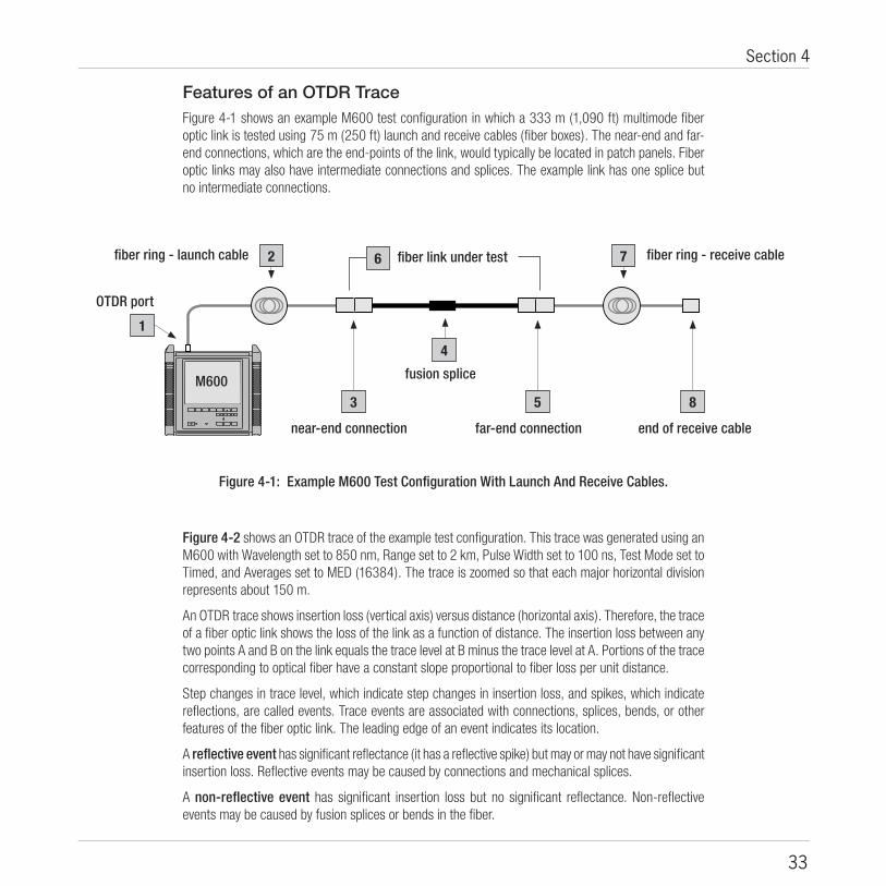
Figure 4-1: Example M600 Test Configuration With Launch And Receive Cables.
F1 F2
fiber ring - launch cable
OTDR port
fiber ring - receive cable
M600
fiber link under test
near-end connection
fusion splice
far-end connection end of receive cable
1
2 6
3 5 8
7
4
Features of an OTDR Trace Figure 4-1 shows an example M600 test configuration in which a 333 m (1,090 ft) multimode fiber optic link is tested using 75 m (250 ft) launch and receive cables (fiber boxes). The near-end and far-end connections, which are the end-points of the link, would typically be located in patch panels. Fiber optic links may also have intermediate connections and splices. The example link has one splice but no intermediate connections.
Figure 4-2 shows an OTDR trace of the example test configuration. This trace was generated using an M600 with Wavelength set to 850 nm, Range set to 2 km, Pulse Width set to 100 ns, Test Mode set to Timed, and Averages set to MED (16384). The trace is zoomed so that each major horizontal division represents about 150 m.
An OTDR trace shows insertion loss (vertical axis) versus distance (horizontal axis). Therefore, the trace of a fiber optic link shows the loss of the link as a function of distance. The insertion loss between any two points A and B on the link equals the trace level at B minus the trace level at A. Portions of the trace corresponding to optical fiber have a constant slope proportional to fiber loss per unit distance.
Step changes in trace level, which indicate step changes in insertion loss, and spikes, which indicate reflections, are called events. Trace events are associated with connections, splices, bends, or other features of the fiber optic link. The leading edge of an event indicates its location.
A reflective event has significant reflectance (it has a reflective spike) but may or may not have significant insertion loss. Reflective events may be caused by connections and mechanical splices.
A non-reflective event has significant insertion loss but no significant reflectance. Non-reflective events may be caused by fusion splices or bends in the fiber.

34
M600 User’s Guide
Figure 4-2: M600 Trace Made Using Launch And Receive Cables.
end of receive cable
far-end connection
fiber link under test4
8
6
7
OTDR port
fiber ring - launch cable
near-end connection
fusion splice
1
3
2
5 fiber ring - receive cable
A fiber-end event marks the end of the OTDR trace. The fiber-end event may indicate a break in the fiber, the end of the fiber link under test, or the end of the receive cable.
The events marked in Figure 4-2 are explained below:
# Trace event Description
1 OTDR port A reflective event caused by the connection between the OTDR and test cable.
2 Launch cable - fiber ring
The launch cable shows the trace level just before (fiber ring) the near-end connection. This makes it possible to measure the insertion loss and precise location of the near-end connection.
3 Near-end connection A reflective event caused by the near-end connection to the link. This event marks the start of the fiber optic link under test.
4 Fiber optic link The portion of the trace showing the fiber loss and length of the link, as well as any events within the link.
5 Fusion splice A non-reflective event caused by a fusion splice in the link.
6 Far-end connection A reflective event caused by the far-end connection to the link. This event marks the end of the link.
7 Receive cable - fiber ring
This portion of the trace makes it possible to see the (fiber ring) trace level just after the far-end connection and therefore to measure the insertion loss of this connection.
8 End of the receive cable The fiber-end event.

35
Section 4
F1 F2 F3 F4 F5
Test JumperFiber Link Under Test
Near-end Connection
Fusion Splice Far-end Connection
M600
Figure 4-3: Using a Test Jumper to Fault-locate a Fiber Optic Link.
near-end connection 1fiber link under test2
far-end connection3
fusion splice 4
Fault Locating To fully analyze a fiber optic link, you must use launch and receive cables (fiber boxes) as shown previously in Figure 4-1. However, to simply locate connections, splices, or faults within a link you need to use only a test jumper as shown below.
To fault locate:
1 Connect the M600 to the near-end connection using a test jumper.
2 Generate a trace using the Manual or Auto Setup procedure (Figure 4-4).
Figure 4-4: M600 Trace Made Using A Test Jumper.

36
M600 User’s Guide
The events marked in Figure 4-4 are explained below:
# Trace event Description
1 Near-end connection A reflective event caused by the near-end connection to the link. This event marks the start of the fiber optic link under test.
2 Fiber optic link The portion of the trace showing the fiber loss and length of the link, as well as any events within the link.
3 Far-end connection A reflective event caused by the far-end connection to the link. This event marks the end of the link.
4 Fusion splice A non-reflective event caused by a fusion splice in the link.
Compare this trace with the one made using launch and receive cables shown in Figure 4-2. Note that if you use only a test jumper, you cannot determine the loss of either the near-end or far-end connection. However, you can locate and measure events and measure the approximate length of the link.

37
Section 5
!
!
Section 5: MaintenanceThis section explains how to maintain your M600 and replace the rechargeable battery.
Repair and Calibration The recommended calibration interval for the M600 is every 12 months. To arrange for the repair or calibration of your M600, please contact Noyes Fiber Systems Customer Service (See “Contacting Customer Service”).
CAUTION: The M600 contains no user-serviceable parts.
Cleaning the Optical Ports M600 optical port connectors must be kept clean to ensure accurate measurements and proper operation.
You can access an M600 optical connector by removing an adapter from the top panel. Remove only the adapter do not remove the adapter plate.
CAUTION: Before doing the following procedure, switch off the M600 and disconnect the AC adapter. Verify that the Power and AC Adapter indicators are off.
To Clean an M600 Optical Port Connector
1 Remove screws that hold the adapter to the mounting block.
2 Remove the adapter.
3 Clean the connector end-face using lint-free wipes (such as Kimwipes®) and optical grade alcohol, industry-approved wet wipes, or dry cleaning cartridges.
4 Blow out the adapter sleeve using compressed, filtered air.
5 Re-attach the adapter to the mounting block using screws.
To Clean a VFI Module Optical Port
1 Remove adapter and sleeve.
2 Perform steps 3 & 4 above.
3 Carefully replace sleeve and re-attach adapter.

38
M600 User’s Guide
!
!
!
Cleaning the Display and CaseThe M600 display and outside of the case may be cleaned using a damp, non-abrasive cloth and mild detergent.
CAUTION: Never use an ammonia-based detergent.
WARNING: Never immerse the M600 in water or let water drip onto the M600.
Battery Charging, Replacement, and Storage.The M600 is equipped with a sealed lead-acid rechargeable battery. Follow the safety considerations and maintenance instructions found on the side of the battery, including the following:
CAUTION:
• Do not incinerate.
• Never directly connect the positive and negative terminals.
• Do not use any battery charger other than one specified for use with the M600 by Noyes Fiber Systems.
Charging
IMPORTANT! During extended periods when your M600 is not operated from AC power, it must be recharged by connecting it to AC power, using the supplied AC adapter, for at least 48 hours every six months. During each 48 hour charging period your M600 may be switched on or off. Failure to follow this minimum charging routine can reduce the useful life of your unit’s internal rechargeable batteries. In rare cases it may also cause a loss of settings that can only be restored by sending your M600 back to the factory.
You may charge the battery with the M600 switched on or off by attaching an AC power adapter. An M600 battery can be recharged to full capacity in about six hours. If the M600 is operating from battery power, and battery capacity reaches about 10%, a Low Battery indication will appear in the upper right-hand corner of the M600 display.
TIP: To insure long battery life, never discharge it completely.
A battery may be charged externally. Wall Mount Battery Charges are available from Noyes Fiber Systems.

39
Section 5
!
Wall Mount Charger Clip-on connector
Battery
To wall outlet
Charge Indicator
Figure 5-1: Charging a Battery Externally.
Figure 5-2: Inserting a New Battery.
To Charge a battery externally:
1 Attach a clip-on connector to the battery (refer to Figure 5-1).
2 Plug the charger into a standard wall outlet.
3 When the battery is charging, the charge indicator goes on.
4 When the charge indicator goes off, the battery is fully charged.
You will need approximately 3.5 hours to fully charge a battery externally.
Replacing
CAUTION: Before doing the following procedure, switch off the M600 and disconnect the AC adapter. Verify that the Power and AC Adapter indicators are off.
To replace the battery:
1 Switch-off the M600 and remove the AC adapter.
2 Remove the thumbscrew ( turn counter clockwise).
3 Remove the battery door.
4 Pull out the discharged battery by the tab and replace it with a charged one. Be sure to orient the battery as shown in Figure 5-2.
5 Replace the battery door and tighten the thumbscrew (clockwise).
Storing
You may store M600 lead-acid batteries indefinitely. However, to maintain their capacity, recharge unused batteries fully about every nine months.
Disposing
Lead acid batteries must be recycled or disposed of properly. Noyes Fiber Systems highly recommends recycling. The batteries used in the M600 are chemically equivalent to car lead-acid batteries and may be recycled by services or companies that accept car batteries.
40
M600 User’s Guide
Section 6: Specifications
Model M600-MM1 M600-SM1
M600 Optical SpecificationsCenter Wavelengths 850 / 1300 nm 1310 / 1550 nm
Fiber type Multimode Single-mode
Dynamic Range 21 / 23 dB 26 / 26 dB
Emitter Type Laser
Emitter Classification Class I (FDA 21 CFR 1040.10 & 1040.11)
Distance Accuracy1 ± 1 m ± 0.5 Resolution ± 0.01%
Display Resolution 0.1 m
Event Dead Zone 5 m
Attenuation Dead Zone 15 m
Number of Data Points Up to 8000
Index of Refraction 1.4000 – 1.6999
M600 General SpecificationsDisplay Type 640 x 480, 7.4 in, color LCD with contrast adjustment
Battery Type Sealed lead-acid (Panasonic SA122R3CU)
File transfer to PC CompactFlash™ reader (USB), 3.5-inch floppy disk
Trace Storage > 1500 CompactFlash™ ; > 350 internal; > 50 per floppy disk
Operating Temperature 5° to +40° C
Storage Temperature -10° to +60° C
Relative Humidity 0 to 95%, non-condensing
Weight In Use <4.5 kg (< 10 lb)
Size (H x W x D) 26.6 x 27.3 x 11.4 cm (10.5 x 10.75 x 4.5 in)
AC Power Adapter AC Input DC Output Use
100 to 240 VAC, 50 – 60 Hz, 1A 18 VDC, 2.2 A maximum
Indoor only Specifications are subject to change. 1To estimate total distance accuracy, add error due to refractive index uncertainty.

41
Section 6
M600-VFI SpecificationsModel M600-VFI
Center Wavelengths 650 nm
Output < 0 dBm (1 mW)
Emitter Type Laser
Emitter Classification FDA 21 CFR 1040.10 & 1040.11 CLASS II, IEC 825-1: 1993 CLASS II,EN60825-1: 1994 CLASS II
Transmission Mode CW or 2 Hz, 50% Duty Cycle
Output Fiber 9/125 µm, single-mode
Optical Connector Cleanable Universal Adapter (2.5 mm)
Specifications are subject to change.
Available M600 Modules and Accessories
Model Description
M600 Modules
M600-K M600 main frame with no modules
M600-MM1-xx Dual multimode module (850/1310 nm)
M600-SM1-yy Dual single-mode module (1310/1550 nm)
M600-K-QUAD-xx-yy M600 equipped with a multimode and single-mode module
M600-VFI M600 equipped with a Visible Fault Identifier, 650 nm, Class II Laser
Accessories
5150-00-0100 External Keyboard
4050-00-0109 Spare AC Adapter - Universal (specify cord type)
3900-02-0100 Spare Battery
4050-30-0102 External battery charger (120 VAC / 60 Hz, plug type: North American)
4050-30-0103 External battery charger (230 VAC / 50 Hz, plug type: European)
Adapter Kits
M600-00-0900 SC Adapter Kit
M600-00-0901 ST Adapter Kit
M600-00-0902 FC Adapter Kit
Available connectors: multimode (xx) = SC or ST; single-mode (yy) = SC, FC, or ST
42
M600 User’s Guide
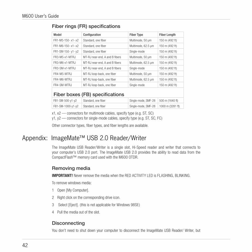
Fiber rings (FR) specifications
Model Configuration Fiber Type Fiber Length
FR1-M5-150- x1- x2 Standard, one fiber Multimode, 50 µm 150 m (492 ft)
FR1-M6-150- x1- x2 Standard, one fiber Multimode, 62.5 µm 150 m (492 ft)
FR1-SM-150- y1- y2 Standard, one fiber Single-mode 150 m (492 ft)
FR3-M5-x1-MTRJ MT-RJ near-end, A and B fibers Multimode, 50 µm 150 m (492 ft)
FR3-M6-x1-MTRJ MT-RJ near-end, A and B fibers Multimode, 62.5 µm 150 m (492 ft)
FR3-SM-x1-MTRJ MT-RJ near-end, A and B fibers Single-mode 150 m (492 ft)
FR4-M5-MTRJ MT-RJ loop-back, one fiber Multimode, 50 µm 150 m (492 ft)
FR4-M6-MTRJ MT-RJ loop-back, one fiber Multimode, 62.5 µm 150 m (492 ft)
FR4-SM-MTRJ MT-RJ loop-back, one fiber Single-mode 150 m (492 ft)
Fiber boxes (FB) specificationsFB1-SM-500-y1-y2 Standard, one fiber Single-mode, SMF-28 500 m (1640 ft)
FB1-SM-1000-y1-y2 Standard, one fiber Single-mode, SMF-28 1000 m (3281 ft)
x1, x2 — connectors for multimode cables, specify type (e.g. ST, SC)y1, y2 — connectors for single-mode cables, specify type (e.g. ST, SC, FC)
Other connector types, fiber types, and fiber lengths are available.
Appendix: ImageMate™ USB 2.0 Reader/WriterThe ImageMate USB Reader/Writer is a single slot, Hi-Speed reader and writer that connects to your computer’s USB 2.0 port. The ImageMate USB 2.0 provides the ability to read data from the CompactFlash™ memory card used with the M600 OTDR.
Removing media IMPORTANT! Never remove the media when the RED ACTIVITY LED is FLASHING, BLINKING.
To remove windows media:
1 Open [My Computer].
2 Right click on the corresponding drive icon.
3 Select [Eject]. (this is not applicable for Windows 98SE)
4 Pull the media out of the slot.
DisconnectingYou don’t need to shut down your computer to disconnect the ImageMate USB Reader/ Writer, but

43
Section 6
you should never remove the device from the USB port without first reading the steps below. If a drive window is open, or the ImageMate USB 2.0 Reader/ Writer is active, close any associated windows before attempting to remove the Reader/ Writer.
Use the [Safe to Remove Hardware] hotplug icon in the notification area of the taskbar or Control Panel and [Add/Remove Hardware] to safely remove the device before unplugging. The notification area is to the right of the taskbar where you usually see the current time displayed.
These steps are not required for Windows 98SE or Windows XP.
1 In the notification area, right-click on the [Safe to Remove Hardware] hotplug icon.
2 Select the device you want to unplug, and then click [Stop].
3 When Windows notifies you that it is safe to do so, unplug the Reader/ Writer from your computer.

44
M600 User’s Guide
Definitions Attenuation Dead Zone - On an OTDR trace, the distance after a reflective event where insertion loss cannot be measured.
Connection - A pair of fiber optic connectors mated through a fiber optic adapter or a mated fiber optic plug and jack. Connections to the near-end/far-end of a fiber optic link or between link sections normally occur at patch panels.
Dead Zone - On an OTDR trace, this is a region after a reflective event in which events cannot be detected (event dead zone) or loss cannot be measured (attenuation dead zone). The event dead zone specification of an OTDR is normally shorter than its attenuation dead zone specification. A dead zone will normally occur at the beginning of every OTDR trace because of unavoidable reflection at the OTDR port. Other dead zones normally occur after connections and mechanical splices. The length of a dead zone depends on the OTDR’s dead zone specifications and the magnitude of the reflection. Dirty connectors often cause large reflections. Therefore cleaning both connectors at a given connection can often reduce its dead zone significantly.
Event Dead Zone - On an OTDR trace, the distance after a reflective event where other reflective events cannot be detected.
Event - On an OTDR trace, a location at which a step-change in level, a spike, or both occur.
Insertion Loss - For an event or a fiber optic link, the ratio of input power to output power, expressed in decibels: 10 log (Pin/Pout).
Fiber Optic Link - An optical fiber path terminated by connectors at optical patch panels. A fiber optic link may be composed of two or more fibers that have been spliced or connected together.
Launch Cable - A launch cable may be used in place of a test jumper to connect an OTDR to a fiber optic link under test. The key difference between a test jumper and launch cable is length. A typical test jumper is less than 3 meters (10 ft) long, whereas launch cables can range from 50 to over 500 meters. On an OTDR trace, a launch cable shifts the location of the near-end connection beyond the attenuation dead zone of the OTDR port. This makes it possible to measure the loss of the near-end connection. A launch cable also makes it easier to locate the near-end connection, resulting in more accurate length measurements. Launch cables are usually composed of a coil of fiber that is mounted and terminated in a small box to make it field-portable.
LSA Line - Least Squared Approximation segment line.
Non-reflective Event - An event that has measurable loss but no measurable reflection (typically caused by a fusion splice or bend in the fiber).
Patch Cord - A short fiber optic cable, typically 1 to 3 meters (3 to 10 ft) long, terminated at each end by a connector. Patch cords are used to make interconnections at patch panels, for example between horizontal and backbone sections of fiber optic links, or between a network equipment and fiber optic links.

45
Section 6
Reflectance - For a reflective event, this is the ratio of reflected power to input or incident power, expressed in decibels: 10 log (Preflected/Pin) dB
Receive Cable - A receive cable is simply a launch cable used to terminate the far-end of the link under test. On an OTDR trace, a receive cable shows the trace level beyond the far-end connection. This makes it possible to measure the loss of the far-end connection.
Reflective Event - An event that has significant reflection, significant insertion loss, or both (typically caused by connections, mechanical splices, breaks in the fiber, or the end of the fiber optic link).
Splice - A permanent joining of two optical fibers using a fusion, mechanical, or adhesive splicing technique.
Test Jumper - A good quality patch cord with clean, undamaged connectors.

46
M600 User’s Guide

Thank you for choosing Noyes Test & Inspection
16 Eastgate Park Road Belmont, NH 03220 Phone: 800-321-5298 603-528-7780Fax: 603-528-2025www.AFLtele.com > Products > Noyes Test & Inspection
���������
�������
�����
T e s t & I n s p e c t i o n


