For More Information On This Product, Go to: www.freescale.com
nc
...
Motorola reserves the right to make changes without further notice to any products herein toimprove reliability, function, or design. Motorola does not assume any liability arising out of theapplication or use of any product or circuit described herein; neither does it convey any licenseunder its patent rights nor the rights of others. Motorola products are not designed, intended, orauthorized for use as components in systems intended for surgical implant into the body, or otherapplications intended to support or sustain life, or for any other application in which the failure ofthe Motorola product could create a situation where personal injury or death could occur. ShouldBuyer purchase or use Motorola products for any such unintended or unauthorized application,Buyer shall indemnify and hold Motorola and its officers, employees, subsidiaries, affiliates, anddistributors harmless against all claims, costs, damages, and expenses, and reasonable attorneyfees arising out of, directly or indirectly, any claim of personal injury or death associated withsuch unintended or unauthorized use, even if such claim alleges that Motorola was negligentregarding the design or manufacture of the part. Motorola is a registered trademark of Motorola,Inc. Motorola, Inc. is an Equal Opportunity/Affirmative Action Employer.
IBM is a trademark of International Business Machines Corp.
MS-DOS is a trademark of Microsoft Corporation.
Fre
esc
ale
Se
mic
on
du
cto
r, I
Freescale Semiconductor, Inc.
For More Information On This Product, Go to: www.freescale.com
nc
...
CONTENTS
M68PCBUG11/D iii
CONTENTS
CHAPTER 1 GENERAL INFORMATION
1.1 INTRODUCTION............................................................................................................. 1-11.2 MCU SETUP FOR PCBUG11 .......................................................................................... 1-1
1.2.1 Hard Disk Installation............................................................................................... 1-21.2.2 Flexible Disk Installation........................................................................................... 1-2
2.2.1 The <baudrate> Parameter ........................................................................................ 2-12.2.2 Runtime Command Examples.................................................................................... 2-3
2.3 USES OF THE SOFTWARE ............................................................................................ 2-32.4 PITFALLS TO AVOID..................................................................................................... 2-4
Fre
esc
ale
Se
mic
on
du
cto
r, I
Freescale Semiconductor, Inc.
For More Information On This Product, Go to: www.freescale.com
4.2.2 Editing Macros......................................................................................................... 4-34.2.3 Listing and Clearing Macros...................................................................................... 4-4
4.3 USING TRACE AND BREAKPOINTS............................................................................ 4-44.3.1 Breakpoints............................................................................................................... 4-44.3.2 Tracing..................................................................................................................... 4-6
4.4 TALKERS IN EEPROM OR EXTERNAL MEMORY ..................................................... 4-64.5 PROGRAMMING EPROM (711) PARTS ........................................................................ 4-84.6 DESIGNING NEW TALKERS......................................................................................... 4-9
Fre
esc
ale
Se
mic
on
du
cto
r, I
Freescale Semiconductor, Inc.
For More Information On This Product, Go to: www.freescale.com
nc
...
CONTENTS
vi M68PCBUG11/D
APPENDIX A HARDWARE SUPPORT
A.1 INTRODUCTION............................................................................................................A-1A.2 CIRCUIT DIAGRAM AND COMPONENTS LIST........................................................A-1
APPENDIX B PCBUG11 ERROR MESSAGES
B.1 INTRODUCTION............................................................................................................B-1B.2 FAILED OPERATION ERRORS.....................................................................................B-1B.3 COMMUNICATIONS ERRORS AND OTHER FATAL ERRORS................................B-4B.4 COMMAND ERRORS.....................................................................................................B-6B.5 VERIFICATION ERRORS ..............................................................................................B-6
APPENDIX C PCBUG11 DISK CONTENTS
Fre
esc
ale
Se
mic
on
du
cto
r, I
Freescale Semiconductor, Inc.
For More Information On This Product, Go to: www.freescale.com
nc
...
GENERAL INFORMATION
M68PCBUG11/D 1-1
CHAPTER 1
GENERAL INFORMATION
1.1 INTRODUCTION
M68HC11 PCbug11 is a software package for easy access to and simple experimentation withM68HC11 microcontroller unit (MCU) devices. PCbug11 lets you program any member of theM68HC11 MCU family and examine the behavior of internal peripherals under specificconditions. In addition, you may run your own programs on the MCU; breakpoint processing andtrace processing are available.
This manual explains how to install and run PCbug11, version 3.24, as well as how to correctcommon problems. (A user who has a later version of PCbug11 should check for any versioninformation notes attached to the end of this manual. Such notes contain information about anychanges from the information of the main text.)
Terminology conventions for this manual are:
• The acronym MCU denotes any member of the family of M68HC11 microcontrollerunit devices.
• Two-character, alphabetic and numerical codes denote specific MCUs. For example,A8, D3, and E9 denote the MC68HC11A8, the MC68HC11D3, and theMC68HC11E9, respectively.
• Monitor, or monitor program, is another term for PCbug11.
1.2 MCU SETUP FOR PCBUG11
Before you use an M68HC11 MCU with PCbug11, you must prepare hardware supportcomponents and install the software on an IBM PC or compatible personal computer. Forinformation on hardware components, consult Appendix A.
Motorola supplies the software on a 360-Kbyte, IBM PC compatible master disk. You mustinstall this software on the hard disk of your computer, per paragraph 1.2.1.
Optionally, if your computer does not have a hard disk, you may run PCbug11 froma flexible disk, per paragraph 1.2.2.
Fre
esc
ale
Se
mic
on
du
cto
r, I
Freescale Semiconductor, Inc.
For More Information On This Product, Go to: www.freescale.com
nc
...
GENERAL INFORMATION
1-2 M68PCBUG11/D
1.2.1 Hard Disk Installation
In these instructions, drive A is the flexible disk drive and drive C is the hard disk. Follow thesesteps to install the software on a hard disk:
1. Insert the master disk in drive A.
2. Make drive C the default drive (if it is not so already) by typingC: [RETURN]
3. Create a new subdirectory by typingmd \PCBUG11 [RETURN]
4. Make this new subdirectory the default byt typingcd \PCBUG11 [RETURN]
5. Copy all the files from the master disk to the hard disk by typingcopy a:*.* c: [RETURN]
This completes software installation. You may run PCbug11 from anywhere in the hard-diskdirectory structure by using the DOS PATH command to include the C:\PCBUG11 subdirectoryin your path. (See DOS documentation for details on the PATH command.)
1.2.2 Flexible Disk Installation
These instructions are for a computer that has two flexible disk drives. Drive A is a 360-Kbyteflexible disk drive. Drive B is the second flexible disk drive. You need a freshly formatted disk,which will become your work disk.
Follow these steps to install the software:
1. Insert the master disk in drive A.
2. Insert the formatted disk in drive B. This disk becomes your work disk.
3. Copy all the files from the master disk to the work disk by typingcopy a:*.* b: [RETURN]
4. Remove the master disk from drive A.
5. Remove the work disk from drive B and insert it in drive A.
This completes software installation. You may run PCbug11 from the work disk in drive A.
Fre
esc
ale
Se
mic
on
du
cto
r, I
Freescale Semiconductor, Inc.
For More Information On This Product, Go to: www.freescale.com
nc
...
GENERAL INFORMATION
M68PCBUG11/D 1-3
1.3 STARTING PCBUG11
To start the software package, set up the hardware, connect the hardware to thecomputer communication port, and run the PCbug11 monitor program.
1.3.1 Running the Software
PCbug11 is sophisticated software that takes many possible options. The computer port used, thecrystal used, and any macros used determine which options are possible for a specific MCU.
To run the software, enter the startup command. The simplest run command is for anMC68HC11A8, MC68HC11A1, or MC68HC11A0 MCU, with the XIRQ and PD0 pinsconnected:
PCBUG11 -XA
To run other MCUs of the M68HC11 family, alter the final one or two characters of this runcommand, per Table 1-1. (As most M68HC11 MCUs have E9 type bootloaders, the -XE optionis the more frequently appropriate.) An X in the run command means that the XIRQ and PD0pins must be connected (do not use the X option if PCbug11 is used with an EVBU board).
NOTE
The default number base of PCbug11 is 10. To change the defaultbase to 16, enter the command CONTROL BASE HEX. Tochange the default base to 2, enter the command CONTROLBASE BIN. To change the default base back to 10, enter thecommand CONTROL BASE DEC. The CONTROL commandexplanation, in Chapter 3, gives more information.
Fre
esc
ale
Se
mic
on
du
cto
r, I
Freescale Semiconductor, Inc.
For More Information On This Product, Go to: www.freescale.com
Hardware status appears on the computer screen. This screen consists of four major areas, orwindows:
1. Main window. This window is the upper half of the screen. If you have a color screen,the main window has white text on a blue background. This window displays the mostinformation about PCbug11 operation: command results, memory contents, assemblyopcodes, macros, and so forth.
2. Register window. This window is in the center of the screen. If you have a colorscreen, the register window has white or yellow text on a red background. Thiswindow shows the last recorded contents of the processor registers. Note that registerwindow values update only upon startup or user request. PCbug11 commands let youmodify the contents of the registers.
Fre
esc
ale
Se
mic
on
du
cto
r, I
Freescale Semiconductor, Inc.
For More Information On This Product, Go to: www.freescale.com
nc
...
GENERAL INFORMATION
M68PCBUG11/D 1-5
3. Status window. This window is at the center right of the screen. If you have a colorscreen, the status window has white text on a purple background. This window showsthe MCU in use; the MCU state (running, stopped, tracing); the status of the RS232RTS line, and the current user-set interrupt vectors.
4. Command window. This window is at the bottom left of the screen. If you have acolor screen, the command window has white text on a black background. Use thiswindow for entering and reading commands to PCbug11. The command cursor (the »character) is at the bottom line of this window; commands you enter appear after thecommand cursor. Previous commands and the latest error message also appear in thecommand window.
If your screen does not show these windows, the program is not running correctly. A DOS errormessage or a PCbug11 error message indicates the problem. See paragraph 1.3.3 or Appendix Bfor guidance on corrective action. If your screen does show these four windows, proceed toparagraph 1.3.4 to try some simple commands.
There are two additional, temporary windows, which appear superimposed over themain window:
1. Error window. This window indicates any errors or incorrectly operatingcommunications to the MCU. If you have a color screen, the error window has redtext on a black background. To clear the error window immediately, press any key.(Or wait five seconds and the error window clears itself.)
2. Help window. This window displays help information requested via the HELPcommand. If you have a color screen, the help window has white text on a blackbackground. To scroll through the help information, use the up-arrow, down-arrow,page-up, and page-down keys. To clear the help window, press the ESC key.
1.3.3 Fixing Simple Problems
If the software did not start up correctly, the register screen shows rows of characters X insteadof values, and one or more error messages appear in the command window. Appendix B explainsthe full meaning of such an error message.
Fre
esc
ale
Se
mic
on
du
cto
r, I
Freescale Semiconductor, Inc.
For More Information On This Product, Go to: www.freescale.com
nc
...
GENERAL INFORMATION
1-6 M68PCBUG11/D
In the case of an initial startup, however, the most likely problems are a poor communications linkor an incorrect hardware setting. Make sure that:
• A 5-volt signal is supplied correctly to the user hardware.
• An 8 MHz crystal is installed in the circuit.
• The communications cable is wired correctly.
• The MCU is in bootstrap mode and is reset.
• The cable is connected to the COM1 port of the computer (or the guidance ofparagraph 2.2 is followed if the cable is connected to the COM2 port).
After checking these items, try again to start the system. If numerical values appear in the registerwindow and there are no error messages, PCbug11 is working correctly. Proceed to the simplecommands of paragraph 1.3.4.
1.3.4 Trying Simple Commands
This paragraph explains a few simple commands that demonstrate PCbug11 operation. (Paragraph3.2 explains the full PCbug11 command set.)
<CTRL>R This command tests communications between the user hardware and thecomputer. If communications are operating correctly, the response
Communications synchronized
appears in the main window. Otherwise, the response
Communications fault
appears in the main window.
RESTART This command reloads the communications program and starts afresh, so itis appropriate any time there is an indication of a communications fault. Besure to reset the MCU before typing in RESTART. Note, however, thatthis command may lead to the loss of any program in processor RAM.
QUIT This command terminates a PCbug11 session. After you type in QUIT , amessage requests confirmation that you really do want to end the session.Respond affirmatively, and the session ends.
RD This command displays register contents, letting you read the values.Should rows of the character X appear instead of values, an error messageidentifies the problem.
Fre
esc
ale
Se
mic
on
du
cto
r, I
Freescale Semiconductor, Inc.
For More Information On This Product, Go to: www.freescale.com
nc
...
GENERAL INFORMATION
M68PCBUG11/D 1-7
MD start_address (end_address) This command displays contents ofmemory, from the start address through the end address. If you do notenter the optional end address, PCbug11 displays the contents of the 16memory locations beginning with the start address. Memory contentsappear in the main window. (If the address values consist only of digits, themonitor considers them decimal numbers. To specify binary or hexadecimaladdresses, start them with the % or $ character, respectively.)
CLS This command clears the main window.
HELP (command) This command is valid only if you have installed the help file. Enter HELPcommand by itself to see a summary of PCbug11 commands. Enter HELPfollowed by another command to see specific help information on the othercommand.
1.4 HOW PCBUG11 WORKS
PCbug11 works differently from most other microcomputer emulators or trainers. Otheremulators run sophisticated programs that communicate with a terminal. Such a program lets theuser execute programs, alter registers, and so forth, but requires a complex hardware platform.
The PCbug11 design, however, takes advantage of the sophistication of the PC. Themicrocomputer need run only a simple program, so the hardware platform also can be simple.PCbug11 carries out emulator functions via serial communication with the PC.
The monitor communicates with the MCU through a low-level program called a talker. PCbug11includes different talkers to support different MCUs and different operating modes. All talkerscommunicate between the SCI port of the MCU and the serial port of the PC. Each talkeroccupies less than 256 bytes of MCU memory space and operates under interrupt. Some talkersuse internal MCU RAM: this approach is the boot method. Other talkers use internal EPROM orother ROM: this approach is the ROMed method.
In the boot method, the PC downloads the talker into MCU internal RAM for each PCbug11startup. Such a download happens via the special bootstrap mode of the MCU. In this mode, theMCU automatically can download a program into its internal RAM and then run the program.This makes it possible to alter internal values, program memory, read and write to chip ports, andperform other functions. This simple approach requires no external hardware except a powersupply, an oscillator, and an RS-232C interface. The limitation of the boot method is its use ofabout 240 bytes of internal RAM, which may be a problem for some users.
In the ROMed method, the PC synchronizes communication with a talker already running on theMCU. This means that the appropriate talker must be programmed into internal or external MCUmemory before the user runs PCbug11. The simplest example of using the ROMed method isplacing the talker in external memory and running the talker every time the MCU is powered up.If the talker is loaded into the MCU's internal EEPROM, no external memory is required.
Fre
esc
ale
Se
mic
on
du
cto
r, I
Freescale Semiconductor, Inc.
For More Information On This Product, Go to: www.freescale.com
nc
...
GENERAL INFORMATION
1-8 M68PCBUG11/D
As a talker is interrupt driven, residing in the same memory map as user software, the RESET,XIRQ, and SWI vectors must be reserved for talker code. Note, however, that the SCI vectormay be used instead of the XIRQ vector, to give maskable control to PCbug11.
The PCbug11 design leads to these rules of thumb:
1. If the PCbug11 is in boot mode, MCU internal RAM contains the talker program,bootstrap-mode interrupt vectors, and the program stack. For an MCU that has 256bytes of RAM, this leaves little room for user programs. In such a case, the usershould use EEPROM space for programs.
2. PCbug11 is interrupt driven, so the user must consider carefully any program that usesinterrupts or changes interrupt vectors. In the standard approach, the XIRQ pin causesan interrupt whenever the user needs communications. This gives the user reasonablyfree use of interrupts that set the I bit. But the user must be careful when usingbreakpoint or trace operations, which also set the I bit. The user also must protect theinterrupt vectors from alteration; changes to these vectors cause loss ofcommunication with the program.
3. PCbug11 implements trace and breakpoint operations by placing a software interruptat the trace or breakpoint location. This means that PCbug11 must be able to modifythe code at such locations: the code must be in (internal or external) RAM orEEPROM. The monitor cannot operate trace or breakpoints in ROM. This restrictionalso applies to FLASH memory, which is not byte programmable. Note that PCbug11makes use of a little software overhead to handle correctly any user-defined SWI.(Breakpoints and tracing are not available with D3 or D0 MCUs.)
Fre
esc
ale
Se
mic
on
du
cto
r, I
Freescale Semiconductor, Inc.
For More Information On This Product, Go to: www.freescale.com
nc
...
USING PCBUG11 SOFTWARE
M68PCBUG11/D 2-1
CHAPTER 2
USING PCBUG11 SOFTWARE
2.1 INTRODUCTION
This chapter introduces the user to several possibilities for using PCbug11 software. Thisdiscussion also covers the runtime command structure and common pitfalls to avoid.
2.2 PCBUG11 RUNTIME COMMAND STRUCTURE
To use PCbug11, enter the runtime command at the DOS prompt. The syntax for this commandis:
Table 2-1 is the key to runtime command symbols and parameters.
2.2.1 The <baudrate> Parameter
If your circuit uses an 8 MHz crystal, the standard for PCbug11, do not use the <baudrate>parameter in the runtime command. In this case, the PC communications rate is 9600 baud, andthe download rate for a -<name> talker is 7812 baud.
For a circuit that uses an alternative crystal, the <baudrate> parameter is required:
• For a <boottype> talker, the <baudrate> value is the download rate for the talker. Thisvalue must be to 7812 as the frequency (in MHz) of your crystal is to 8. That is,
<baudrate> = * 7812crystal used MHz
8
• For a <ROMtype> talker, the <baudrate> value is the communications rate for the PCand MCU. This value must be to 9600 as the frequency (in MHz) of your crystal is to8. That is,
<baudrate> = * 9600crystal used MHz
8
Fre
esc
ale
Se
mic
on
du
cto
r, I
Freescale Semiconductor, Inc.
For More Information On This Product, Go to: www.freescale.com
nc
...
USING PCBUG11 SOFTWARE
2-2 M68PCBUG11/D
Table 2-1. Runtime Command Parameter Key
Symbol or Parameter Explanation or Role
[ ] Enclose optional parameters.
| Indicates or .
? The query option. Enter this option to see a short form of theruntime command syntax, if you need a reminder.
talker The talker to be used. If a hyphen precedes this parametervalue, the file TALK<boottype>.BOO/.XOO must be in thesame directory as the file PCBUG11.EXE. This parameter hastwo forms, <boottype> or <ROMtype> .
<boottype> A , D, E, K, 88, or <userdefined>
<ROMtype> The name of a user-defined ROMed talker. The user mustsupply a file called <ROMtype>.MAP in the current directory.
<baudrate> The baudrate for the PC and MCU if your circuit does not usean 8 MHz crystal. Paragraph 2.2.1 explains more about thisparameter.
<macroname> The name of a macro library file, such as <macroname>.MCR.PCbug11 automatically loads such a macro upon startup.PCbug11 also automatically executes this macro if theadditional macro AUTOSTART also is in the library. To passparameters to this macro, enclose them in parenthesesimmediately after the macro= option.
port=2 The command to use PC port 2, instead of the default port 1,for communications with the hardware.
Fre
esc
ale
Se
mic
on
du
cto
r, I
Freescale Semiconductor, Inc.
For More Information On This Product, Go to: www.freescale.com
nc
...
USING PCBUG11 SOFTWARE
M68PCBUG11/D 2-3
2.2.2 Runtime Command Examples
Some examples of the PCbug11 runtime command are:
PCBUG11 Entering the runtime command without any options invokes the commandline compiler. This lets the user input option information by answering aseries of prompts instead of making option information part of the runtimecommand. This form of the runtime command may be appropriate if youconvert from one MCU to another or if you try a new option.
PCBUG11 ? Entering the runtime command with the query option tells the monitor todisplay a short form of the runtime command syntax.
PCBUG11 -E This form of the runtime command runs the boot option talker for an MCUof the M68HC11E, F, G, or L series. The monitor program downloads thetalker to RAM, then runs the talker.
PCBUG11 -XA port=2 This form of the runtime command runs the boot option talker foran M68HC11A8, A1, A0, or E2 MCU, using PC port 2 (if port 2 exists).The monitor program downloads the talker to RAM, then runs the talker.
PCBUG11 -XE macro=TRYIT This form of the runtime command runs the boot optiontalker for an MCU of the M68HC11E, F, G, or L series and also loads themacro TRYIT.MCR. If the AUTOSTART macro is in the macro library,TRYIT execution begins automatically. (Paragraph 4.2 gives moreinformation about macros.)
PCBUG11 TALKEREE baud=4800 macro=LISTIT (1 2 3) For this form of the runtimecommand, the talker TALKEREE already must be loaded in the MCU. Thevalue 4800 is the PC-to-MCU communications rate that corresponds to a 4MHz crystal. This command also loads the macro LISTIT.MCR and passesthe parameters 1 2 3. (Note that for correct operation of this talker,PCbug11 must be able to load the file TALKEREE.MAP, which containsnecessary system variables. TALKEREE.MAP must be in the user's currentworking directory. Paragraph 4.4 explains more details.)
2.3 USES OF THE SOFTWARE
Possible uses for the PCbug11 software are unlimited. Note that the PCbug11 is not a softwaresimulation of an MCU; commands and programs you enter run on the real hardware, although viaa software interface. Most of the time the hardware runs the MCU in special bootstrap mode, soaccess to secured resources is at user discretion, not under MCU control.
As the package runs under interrupt, it is possible to have a program running, but still be able toread registers, write to registers, and even write to memory. A careful user can even modify the
Fre
esc
ale
Se
mic
on
du
cto
r, I
Freescale Semiconductor, Inc.
For More Information On This Product, Go to: www.freescale.com
nc
...
USING PCBUG11 SOFTWARE
2-4 M68PCBUG11/D
program being run. Note that during modification of a program or registers, the running programwaits for processing of the interrupt caused by PCbug11.
You may set breakpoints in the software, so the MCU stops whenever it reaches that point in thecode. The trace command lets you step through code to examine the execution of instructions,and see the results in registers and in the condition code register (CCR).
PCbug11 lets the user modify and assemble code into EEPROM as if it were RAM. Although theMCU has an elaborate routine for programming this memory, PCbug11 handles suchprogramming in a manner transparent to the user. To make this possible, the user must first usethe EEPROM command to define the area of internal EEPROM. Do not, however, specifyexternal EEPROM in this way, as the talker automatically handles slow external memories. Thereis a significant difference in response times between writing to EEPROM and writing to RAM.
2.4 PITFALLS TO AVOID
Some MCUs have a register that increases EEPROM protection. This is the BPROT register,which usually is at address $1035. Before either the EEPROM or the CONFIG register can beprogrammed, the BPROT register must be modified. Note that PCbug11 does not modify theBPROT register.
If you program the CONFIG register, remember that the contents of this register usually are notreadable until after MCU reset. Note that if the MCU is reset in bootstrap mode, certainautomatic functions place the part in an appropriate operating mode. If the MCU has a securitymode, clearing the NOSEC bit protects the internal RAM, internal EEPROM, and the internalCONFIG register. This means that if the part is reset in bootstrap mode, the value of the NOSECbit will be 1.
Follow these guidelines to use interrupts with the hardware. Real-time and other such interruptsare permitted when the I bit (RTII for the real-time interrupt) is clear and the appropriateinterrupt mask is set. An interrupt sets the interrupt I flag. A CLI or RTI instruction clears thisflag; note however, that the flag for an interrupt source remains set. For a real-time interrupt, thisis RTIF; an exit from a real-time interrupt service routine that leaves RTIF set causes anotherinterrupt immediately. This means that communications with PCbug11 could stop making sense orthat communications could cease (due to stack overflow).
When real-time measurements or calculations are in progress, remember that reading registers ormemory causes interrupts that interfere with logical program operation. This could upset results,generating wrong answers. Such wrong answers are particularly likely when the processor iswaiting for the logical value on a port pin to change before carrying out some action. If thechange occurs while PCbug checks the processor status, the change could be lost or upset.Remember that the MCU does its own self-examination; this self-examination does not affectprograms that perform off-line calculations or other functions.
Fre
esc
ale
Se
mic
on
du
cto
r, I
Freescale Semiconductor, Inc.
For More Information On This Product, Go to: www.freescale.com
nc
...
USING PCBUG11 SOFTWARE
M68PCBUG11/D 2-5
PCbug11 implements breakpoints and traces via software interrupts (SWIs). When programexecution arrives at a breakpoint, an interrupt is generated; the internal talker handles thisinterrupt. If the user directly uses the SWI, the SWI vector is called. If the SWI is a truebreakpoint, the PC so informs the user. While this common emulator arrangement is effective, it islimited to use with RAM or EEPROM; ROM does not accomodate breakpoints or traces. Thereis another problem if you reset or restart the MCU while all breakpoints are still set: the SWIsremain in memory (especially EEPROM), displacing other opcodes. To prevent such a situation,either clear all breakpoints before resetting or restarting the MCU, or reload your codeimmediately after a reset or restart.
In bootstrap mode, PCbug11 puts its talker in MCU internal RAM. Overwriting any of the talkersoftware could cause loss of operations or communications with the MCU. Accordingly, youshould not place any user code or data in the same area as the talker.
This rule applies as well to the interrupt vector area of RAM. Interrupt vectors are redirectedfrom bootstrap ROM; they indicate that communications are required. If the stack is not initializedto a suitable value, the interrupt vectors could be altered accidentally. For example, if youinitialized the stack to $FF, the first interrupt vector received would overwrite the redirectedvectors, causing loss of communications with the MCU. (Disabling bootstap ROM also causescommunications to fail.)
You may cause problems if you put a G command in a macro, followed by other commands thatmodify memory associated with the program. As there is no way to know where the program is inits execution, a macro may modify memory before or during the program's memory operation.(Remember that PCbug11 commands operate under interrupts that temporarily halt the program.)For example, such a situation could change the correct order of value storage in a memorylocation, leading to incorrect operation or inaccurate results. To prevent such a problem, do notuse the G command together with a memory modify command in macros.
Also note that different boot talkers initialize the stack to different values, according to theavailability of RAM. These default values are:
A: $EB D: $EB E: $1FF K: $1FF 88: $EB
Be careful about moving from one processor to another, when the stack pointer value is different.
Fre
esc
ale
Se
mic
on
du
cto
r, I
Freescale Semiconductor, Inc.
For More Information On This Product, Go to: www.freescale.com
nc
...
USING PCBUG11 SOFTWARE
2-6 M68PCBUG11/D
Fre
esc
ale
Se
mic
on
du
cto
r, I
Freescale Semiconductor, Inc.
For More Information On This Product, Go to: www.freescale.com
nc
...
USING PCBUG11 COMMANDS
M68PCBUG11/D 3-1
CHAPTER 3
USING PCBUG11 COMMANDS
3.1 INTRODUCTION
This chapter provides full details about all PCbug11 monitor commands. The first information ofthis chapter explains command-line editing. A table then summarizes all the monitor commands.Complete information about each command follows, in alphabetical order.
3.2 COMMAND-LINE EDITING
Use the host-computer keyboard to edit the PCbug11 command line. A recall buffer holds the last16 commands entered. Table 3-1 lists the edit keys.
Table 3-1. Command Line Edit Keys
Key Function
Left arrow Moves cursor back one character.
Right arrow Moves cursor forward one character.
Home Moves cursor to the first character.
End Moves cursor to the last character.
Delete left Deletes to the left of the cursor.
Del Deletes at the cursor position.
<CTRL> End Deletes from the cursor position to the end of the line.
Ins Inserts at the cursor position.(1)
Up arrow Recalls previous commands, in reverse order.
Down arrow Recalls last command in recall buffer.
Esc Clears command line, or terminates most commands (such asASM, DASM, and MD) in progress.
1. The normal cursor changes to a blocked cursor.
Fre
esc
ale
Se
mic
on
du
cto
r, I
Freescale Semiconductor, Inc.
For More Information On This Product, Go to: www.freescale.com
nc
...
USING PCBUG11 COMMANDS
3-2 M68PCBUG11/D
The four lines above the command line serve as a trace of the last four commands. The fifth lineabove the command line shows breakpoints and the last error encountered.
Possible error codes are:
0 : No error
1 : VERF error
2 : MS or BF error
3 : Talker communication failure
For MS-DOS batch files, an error code can be checked via ERRORLEVEL afterPCbug11 terminates.
3.3 PCBUG11 COMMANDS
Table 3-2 is a summary of PCbug11 commands. Explanations of each command follow this table,in alphabetical order.
Table 3-2. PCbug11 Commands
Command Description
ASM addr [mne|dir](1)(2) Call symbolic macro line assembler, with option toauto-insert mnemonic or directive
BAUD [rate](2) Display or set serial baud rate
BF addr1 [addr2] byte|word(1) Block fill memory with byte or word
BL(2) Display breakpoints
BR [addr [macroname]](1) Display or set breakpoint [with optional commandexecution]
CALL addr Execute the subroutine at addr
CLRM Clear all command macros
CLS Clear main window
CONTROL [parameter] Display or change PCbug11 system parameters
DASM addr1 [addr2] Disassemble from addr1 [to addr2]
DB startaddr [endaddr](2) Display MCU memory
DEBUG Reserved word
Fre
esc
ale
Se
mic
on
du
cto
r, I
Freescale Semiconductor, Inc.
For More Information On This Product, Go to: www.freescale.com
nc
...
USING PCBUG11 COMMANDS
M68PCBUG11/D 3-3
Table 3-2. PCbug11 Commands (continued)
Command Description
DEFINE symbol value|address(2) Define a symbol
DEFM macrname|TRACE|AUTOSTART Define a command, trace, or autostart macro
DELM macrname|TRACE|AUTOSTART Delete a command, trace, or autostart macro
DIR [mask] Display disk directory
DOS [command] Shell to DOS or execute DOS command
EDITM macrnam Edit a macro
EEPROM [startaddr [endaddr]] Display, clear, or set EEPROM address range(s)
EEPROM DELAY option Set EEPROM erase or write programming time
EEPROM ERASE [option] [addr] Display or change EEPROM erase-before-writefunction
EPROM [startaddr [endaddr]] Display, clear, or set EPROM address range(s)
EPROM DELAY option Set EPROM erase or write programming time
FIND byte|word addr1 addr2 Find all occurrences of byte or word between addr1and addr2
FIND mnemonic addr1 addr2 Find all occurrences of mnemonic between addr1 andaddr2
G [addr](1)(2) Start user code execution
HELP [command](1)(2) Display help information
KLE Kill last error message
LOADM [filename [macroname]] Load macro definitions from default or user file
LOADS filename [loadaddr] Load S-record file into MCU memory
LS symbol(2) Display symbols
LSTM [mname|TRACE|AUTOSTART] Display macro names or definitions
MD startaddr [endaddr](1) Display MCU memory
MM addr(1) Modify memory from addr
MOVE addr1 addr2 addr3 Move MCU memory between addr1 and addr2 toaddr3
MS addr byte|word [byte|word] Set MCU memory byte(s) or word(s)
Fre
esc
ale
Se
mic
on
du
cto
r, I
Freescale Semiconductor, Inc.
For More Information On This Product, Go to: www.freescale.com
nc
...
USING PCBUG11 COMMANDS
3-4 M68PCBUG11/D
MSG [string] Display message in main window
Fre
esc
ale
Se
mic
on
du
cto
r, I
Freescale Semiconductor, Inc.
For More Information On This Product, Go to: www.freescale.com
nc
...
USING PCBUG11 COMMANDS
M68PCBUG11/D 3-5
Table 3-2. PCbug11 Commands (continued)
Command Description
NOBR [address](1) Remove all or specified breakpoints
PAUSE [ms] Wait for any key press or delay time
PRINT Display PCbug11 version number
PROTECT [startaddr [endaddr]] Display, clear, or set write-protected address range(s)
RESET [addr] MCU hardware reset with existing or new reset vector
RESTART [option] Restart PCbug11 with same or new option
RM(1) Modify MCU registers in window
RS register value(2) Set value of MCU regisiter
S Stop user code execution
SAVEM [filename] Save macro definitions in default or user file
SHELL [command](2) Shell to DOS or execute DOS command
T [addr](2) Trace user code
TERM [X1 Y1 X2 Y2] Simple windowed terminal emulator
TYPE filename Display disk file in main window
UNDEF symbol(2) Undefine a symbol
VER(2) Display version number
VERF filename [memaddr] Verify S-record disk file against memory
VERF ERASE addr1 [addr2] Verify that memory contains $FF
VERF SET addr1 addr2 value Verify that memory contains the value
WAIT [ms](2) Wait for ms
CTRL B(3) Send break on COM channel
CTRL P(3) Toggle MCU memory write protect/RTS line
CTRL R(3) Try to re-synchronize talker
Fre
esc
ale
Se
mic
on
du
cto
r, I
Freescale Semiconductor, Inc.
For More Information On This Product, Go to: www.freescale.com
nc
...
USING PCBUG11 COMMANDS
3-6 M68PCBUG11/D
1. Commands that operate similarly to the same commands of Motorola M68C11 EVM systems.2. Commands that operate similarly to the same commands of Motorola CDS8 systems.3. Special key operations
Fre
esc
ale
Se
mic
on
du
cto
r, I
Freescale Semiconductor, Inc.
For More Information On This Product, Go to: www.freescale.com
nc
...
USING PCBUG11 COMMANDS
M68PCBUG11/D 3-7
ASM addr [mne|dir] Call symbolic macro lineassembler, with option to auto-insert mnemonic or directive
This command provides single-line assembly/disassembly in the main window.
The assembler is a single-pass version of ASMHC11 2.6, supporting the same mnemonics anddirectives. Symbols can be defined within ASM via the standard Motorola syntax. Alternatively,symbols from an equate file may be loaded via the INCL operand. At least one space mustseparate the > prompt and the mnemonic; otherwise PCbug11 treats the mnemonic as a label.
These keys have special editing roles for the ASM command:
Up arrow Decrement program counter by one
Down arrow Increment program counter by one
Enter Move program counter to the next instruction boundary
Esc Exit ASM and return to the command line
Other editing keys have the same roles for ASM as they do for other commands.
PCbug11 lets you specify an optional mnemonic or directive on the command line. If you do so,the ASM command automatically inserts the mnemonic or directive, then immediately returns tothe command line. This permits mnemonic insertion or directive execution from within a macro,without any user input.
Usage:
ASM $100 Assemble from memory address $100
ASM $100 INCA Insert the INCA instruction at memory address $100
For More Information On This Product, Go to: www.freescale.com
nc
...
USING PCBUG11 COMMANDS
3-8 M68PCBUG11/D
Table 3-3. ASM Error Message Codes
Code Category and Meaning
1 Memory fault : memory did not modify as expected
200 Syntax : invalid character in context
202 Syntax : syntax error
204 Syntax : label required (for EQU or SET)
212 Operand : improper termination of operand field
213 Operand : invalid addressing mode for operand
214 Address : invalid forward reference
223 Address : invalid addressing mode for M68HC11 MCU
234 Symbol : redefined symbol
235 Symbol : undefined symbol
238 Symbol : undefined operation
320 Symbol : error table overflow
321 Symbol : symbol table overflow
250 Data: displacement too large (normally branch)
251 Data: value out of range
252 Data: address too large for forced direct
255 Data: division by zero
501 File : File not found
Fre
esc
ale
Se
mic
on
du
cto
r, I
Freescale Semiconductor, Inc.
For More Information On This Product, Go to: www.freescale.com
nc
...
USING PCBUG11 COMMANDS
M68PCBUG11/D 3-9
BAUD [rate] Display or set serial baud rate
This command lets the user change the serial baud rate of the PC. This command accesses thecomputer hardware directly, permitting a wider range of baud rates than the MODE commandcan select. After PCbug11 executes the rate change, the new baud rate appears on the screen.Values beyond 9600 are available; the maximum baud rate is 38,400.
Usage:
BAUD Display current serial baud rate
BAUD 19200 Change baud rate to 19,200
NOTES
To maintain talker contact, first set the MCU baud rate to the newvalue. Do this either by changing the appropriate talker code or byusing the MS command to change the MCU baud rate registerdynamically.
The default bootstrap download baud rate is 7812; the defaulttalker communication baud rate is 9600. You may specify differentrates when you start PCbug11 from the MS-DOS command line.Thus, PCbug11 and talker codes work without modific-ation withdifferent MCU crystal frequencies. For example, to start anMC68HC11A8 with a 4 MHz crystal, use the command PCBUG11-A 3906. This tells PCbug11 to use half the default values for bothdownload and talker communication.
Changing the baud rate affects the minimum EEPROMprogramming time, as the EEPROM programming algorithm relieson the serial data transfer time.
Related commands: none
Fre
esc
ale
Se
mic
on
du
cto
r, I
Freescale Semiconductor, Inc.
For More Information On This Product, Go to: www.freescale.com
nc
...
USING PCBUG11 COMMANDS
3-10 M68PCBUG11/D
BF addr1 [addr2] byte|word Block fill memory with byte orword
This command forces an 8- or 16-bit value into address addr1 of MCU memory. If addr2 also isspecified, BF forces the value into the block of memory from address addr1 through addressaddr2. If addr1 is in an EEPROM block, an EEPROM algorithm stores the value (the differenceis transparent to the user). This command includes automatic verification of the memory fill.
Usage:
BF $1000 $AA Assign value $AA to address $1000
BF $C000 $CFFF $D3 Assign value $D3 to addresses $C000—$CFFF
BF $00 $FF $AA55 Assign alternate values $AA and $55 to addresses $00—$FF
BF $100 $120 0 1 Assign alternate values 0 and 1 to addresses $100—$120
NOTE
To set the memory value to $00, do not specify the $00 in the mostsignificant byte of a 16-bit value. PCbug11 interprets such aspecification as an 8-bit value, leading to incorrect MCU memoryaddressing.
Related commands: DB, MD, MS
Fre
esc
ale
Se
mic
on
du
cto
r, I
Freescale Semiconductor, Inc.
For More Information On This Product, Go to: www.freescale.com
nc
...
USING PCBUG11 COMMANDS
M68PCBUG11/D 3-11
BL Display breakpoints
This command displays the list of current breakpoints. The hexadecimal address of eachbreakpoint appears on the screen, followed (in parentheses) by the name of any defined macro.
Usage:
BL Display addresses of all user-defined breakpoints
Related commands: BR, NOBR
Fre
esc
ale
Se
mic
on
du
cto
r, I
Freescale Semiconductor, Inc.
For More Information On This Product, Go to: www.freescale.com
nc
...
USING PCBUG11 COMMANDS
3-12 M68PCBUG11/D
BR [addr [macroname]] Display or set breakpoint [withoptional command macroexecution]
This command displays breakpoints or sets an entry in a breakpoint table. Breakpoints are set inMCU memory only when the user starts execution of code via the G command. Before passingcontrol to user code, PCbug11 places an SWI instruction at every breakpoint address in thebreakpoint table. PCbug11 also handles user-placed SWIs (though using some overhead), if theuser SWI vector is downloaded from an S-record file via the LOADS command, and if there areno breakpoints at the user SWI instructions. Note that when PCbug11 first starts, it treats theMCU SWI vector as a user SWI vector.
If you use the BR command to set a breakpoint and you specify a macro in the macronameoption, that macro starts when code execution reaches the breakpoint. (If no such macro hasbeen defined, PCbug11 ignores this optional command entry.)
If you use the BR command to display breakpoints and you specify the associated macro in themacroname option, the macro name (in parentheses) follows the breakpoint in the display. If themacro specified is not currently defined, the macro name follows the breakpoint in the display, butwith a question-mark indicator. If no such macro is defined, the indicator "—" follows thebreakpoint in the display.
Usage:
BR Display addresses of all user-defined breakpoints
BR $C0F1 $C045 Set breakpoints at MCU addresses $C0F1 and $C045
BR $C023 DISPREG Set breakpoint at MCU address $C023; execute macro DISPREGwhen execution reaches this breakpoint
Related commands: BL, NOBR
Fre
esc
ale
Se
mic
on
du
cto
r, I
Freescale Semiconductor, Inc.
For More Information On This Product, Go to: www.freescale.com
nc
...
USING PCBUG11 COMMANDS
M68PCBUG11/D 3-13
CALL addr Execute the subroutine at addr
This command directs the monitor to execute the MCU code at addr. (The MCU code must endwith an RTS instruction.) The CALL command has the same effect as the MCU instruction JSR<addr>; the CALL command does not affect the current state of the monitor.
Usage:
CALL $100 Execute the subroutine at address $100
Related command: G, S
Fre
esc
ale
Se
mic
on
du
cto
r, I
Freescale Semiconductor, Inc.
For More Information On This Product, Go to: www.freescale.com
nc
...
USING PCBUG11 COMMANDS
3-14 M68PCBUG11/D
CLRM Clear all command macros
This command removes all macro names and definitions (including the TRACE macro) from thecurrent library. The CLRM command does not affect libraries stored on disk via the SAVEMcommand.
Usage:
CLRM Clear macro names and definitions from the library
Related commands: DEFM, DELM, EDITM, LOADM, LSTM, SAVEM
Fre
esc
ale
Se
mic
on
du
cto
r, I
Freescale Semiconductor, Inc.
For More Information On This Product, Go to: www.freescale.com
nc
...
USING PCBUG11 COMMANDS
M68PCBUG11/D 3-15
CLS Clear main window
This command clears the main window of the screen, and clears any error orbreakpoint messages.
Usage:
CLS Clear the screen main window
Related command: KLE
Fre
esc
ale
Se
mic
on
du
cto
r, I
Freescale Semiconductor, Inc.
For More Information On This Product, Go to: www.freescale.com
nc
...
USING PCBUG11 COMMANDS
3-16 M68PCBUG11/D
CONTROL [parameter] Display or change PCbug11system parameters
This command, without the parameter option, lists all the PCbug11 parameters that the user canmodify. With a parameter specified, this command changes the parameter value. The usageparagraph, below, shows the available parameters.
At startup, PCbug11 determines if hardware access in the communications port is possible. If so,it uses this mode and enables direct RTS line control. If not, PCbug11 uses BIOS calls to theCOM port. The RTS line can be programmed as a write-protect logic level for systems withexternal memory (see paragraph 4.4).
COM1 is the default communications port; the user can change this by adding port=2 to thecommand line (as in PCBUG11 -XA port=2). PCbug11 sets up PPROG and EPROG values, tothe same address if the part operates that way. Note that the code presumes that the bit positionsof these registers are those of the 711E9 MCU.
Usage:
CONTROL HARDWARE Access serial COM port directly through hardware
CONTROL BIOS Access serial COM port through BIOS calls
CONTROL RTS Control RTS directly
CONTROL PROTECT Use RTS to provide memory write-protection
CONTROL TIMEOUT value Specify value of serial COM timeout during input
CONTROL COM1 Use COM1 port
CONTROL COM2 Use COM2 port
CONTROL ERRMSG 0 Disable display of memory error messages
CONTROL ERRMSG 1 Enable display of memory error messages
CONTROL LAST Toggle the last error message window on or off
CONTROL PPROG address Change the EEPROM register address
CONTROL EPROG address Change the EPROM register address
A special use of the CONTROL command is the BASE option, which lets you change thePCbug11 default number base. At startup, the PCbug11 default number base is 10. To change thedefault base or return to base 10, follow these examples:
CONTROL BASE HEX Change default base to 16
CONTROL BASE DEC Change default base back to 10
CONTROL BASE BIN Change default base to 2
Related commands: DEFM, LOADM, SAVEM (for details of macro libraries)
Fre
esc
ale
Se
mic
on
du
cto
r, I
Freescale Semiconductor, Inc.
For More Information On This Product, Go to: www.freescale.com
nc
...
USING PCBUG11 COMMANDS
M68PCBUG11/D 3-17
DASM addr1 [addr2] Disassemble from addr1 [toaddr2]
This command disassembles MCU memory, showing disassembled code in the main window. Ifyou specify both addr1 and addr2 values, DASM disassembles code from addr1 to addr2. If youspecify only the addr1 value, DASM starts at addr1, disassembling 15 bytes of code (plus anyadditional bytes needed to finish an instruction). A special case of using only the addr1 parameteris to give it the current value of the program counter. In this case, DASM disassembles one line ofcode.
Screen display of disassembled code stops when the screen is filled. To continue the display, pressany key except ESC. To terminate disassembly, press the ESC key.
Using the DASM command is a convenient way to trace program code when using a trace macro.Such a macro should contain the command DASM *.
For More Information On This Product, Go to: www.freescale.com
nc
...
USING PCBUG11 COMMANDS
3-18 M68PCBUG11/D
DB startaddr [endaddr] Display MCU memory
This command displays the contents of memory, from startaddr through endaddr. If the commanddoes not include an endaddr value, PCbug11 displays the contents of 15 memory loactions,starting with startaddr.
Usage:
DB $1000 Display contents of memory addresses $1000—$100F
DB $C000 $CFFF Display contents of memory addresses $C000—$CFFF
Related commands: BF, MD, MS
Fre
esc
ale
Se
mic
on
du
cto
r, I
Freescale Semiconductor, Inc.
For More Information On This Product, Go to: www.freescale.com
nc
...
USING PCBUG11 COMMANDS
M68PCBUG11/D 3-19
DEBUG Reserved word
This command is reserved for developmental use. Do not use DEBUG as a label.
Fre
esc
ale
Se
mic
on
du
cto
r, I
Freescale Semiconductor, Inc.
For More Information On This Product, Go to: www.freescale.com
nc
...
USING PCBUG11 COMMANDS
3-20 M68PCBUG11/D
DEFINE symbol value|address Define a symbol
This command explicitly defines a symbol and specifies the symbol value. The symbol consists ofcase-sensitive letters (abc does not equal ABC). The symbol value is a specific value or theaddress of the memory location that contains the value. Such symbols can be more obviouslysignificant than numerical values in some contexts. PCbug11 reads such a symbol as if reading thevalue. A disassembly listing shows the symbol, not the value, for better readability.
Usage:
DEFINE PORTA $1000 Define symbol PORTA = $1000
DEFINE mask1 45 Define symbol mask1 = 45 ($2D)
Related commands: LS, UNDEF
Fre
esc
ale
Se
mic
on
du
cto
r, I
Freescale Semiconductor, Inc.
For More Information On This Product, Go to: www.freescale.com
This command lets the user create a command sequence (a macro) that can be executed merely bytyping the name of the macro. As many as 10 parameters can be passed to a command macro.Within the macro, the required parameter is specified by the operator @N, where N is a single-digit number, 0—9. The syntax and use of pass parameters is the same as in Motorola assemblers.The macrnam can be any sequence of alphanumeric characters except reserved words. More thanone macro is allowed at the same time; macros can be nested in as many as five levels. Macros areheld in macro libraries, which can be saved on disk, then reloaded as needed.
Use the main window for the macro definition. The definition may include the names of othermacros. To end the definition, press the ENTER/RETURN key on a blank line. A defined macrocan be edited within PCbug11 via the EDITM command. The macro also can be edited via astandard text editor once the file has been saved. This is because PCbug11 saves macros in aspecial text format (see LOADM). (Using the text editor is another way to define a macro, if thedefinition is in the special text format.)
NOTE
If the specified macro name already exists, the new macro definitionoverwrites the old.
The reserved parameter name TRACE lets the user define a macro that is executed at thecompletion of every T (trace) command.
The reserved parameter name AUTOSTART lets the user define a macro that is executedautomatically during PCbug11 startup. To enable this autostart feature, use the SAVEMcommand to save the macro library that contains the AUTOSTART macro. Then, from MS-DOS,specify the macro library name as the last parameter on the command line. For example, fromPCbug11:
DEFM AUTOSTART(Type macro definitions in main window, then press the ESC key.)
SAVEM STARTUPQUIT (To quit PCbug11)
Then, from the PC command line:
PCBUG11 -XA STARTUP
(Loads STARTUP library, executes AUTOSTART.)
Fre
esc
ale
Se
mic
on
du
cto
r, I
Freescale Semiconductor, Inc.
For More Information On This Product, Go to: www.freescale.com
This command deletes a macro definition, freeing memory space for other use.
Usage:
DELM CONFIG Delete CONFIG macro name and definition
DELM TRACE Delete macro name and definition used by the T command
DELM AUTOSTART Delete autostart macro
Related commands: CLRM, DEFM, EDITM, LOADM, LSTM, SAVEM
Fre
esc
ale
Se
mic
on
du
cto
r, I
Freescale Semiconductor, Inc.
For More Information On This Product, Go to: www.freescale.com
nc
...
USING PCBUG11 COMMANDS
3-24 M68PCBUG11/D
DIR [mask] Display disk directory
This command displays the contents of the current directory, or of the directoryspecified by the mask parameter.
Usage:
DIR Display contents of the current directory
DIR *.MCR Display all current-directory files that have the extension .MCR(macros)
DIR \ Display all files in the root directory
DIR ..\*.PAS Display all files in the directory above the current one that havethe extension .PAS
Related command: TYPE
Fre
esc
ale
Se
mic
on
du
cto
r, I
Freescale Semiconductor, Inc.
For More Information On This Product, Go to: www.freescale.com
nc
...
USING PCBUG11 COMMANDS
M68PCBUG11/D 3-25
DOS [command] Shell to DOS or execute DOScommand
This command causes PCbug11 to shell to MS-DOS. If this command includes a specifiedcommand parameter, PCbug11 shells to MS-DOS and executes the command. Then programcontrol returns to PCbug11.
If this command does not have a specified command parameter, program control remains in DOS.The simple way to return to PCbug11 is to type EXIT at the DOS prompt. Optionally, to carryout other actions while returning to PCbug11, the user can run the program PCBUGRTN.EXE.(The user may customize the PCBUGRTN.EXE program, as appropriate.)
If used, the program PCBUGRTN.EXE must be stored in the same directory asPCBUG11.EXE.
Usage:
DOS COPY *.TXT a:/V Shell to DOS, execute command, and return to PCbug11
Related commands: SHELL
Fre
esc
ale
Se
mic
on
du
cto
r, I
Freescale Semiconductor, Inc.
For More Information On This Product, Go to: www.freescale.com
nc
...
USING PCBUG11 COMMANDS
3-26 M68PCBUG11/D
EDITM macrnam Edit a macro
This command lets the user edit a macro already defined and loaded into PCbug11. As many as 10lines of the macro appear on the screen. Table 3-4 lists the EDITM edit keys.
To move from line to line, press an arrow key. There is no direct command to delete a line; afterthe edit, PCbug11 automatically removes lines that contain no characters. Similarly, PCbug11removes any leading spaces from lines.
If the named macro does not exist, the EDITM command creates the macro as a null macro. If theuser edits a null macro, only the first (blank) line of the macro appears.
Table 3-4. EDITM Edit Keys
Key Function
Alphanumeric If the insert function is on, inserts the new character before thecurrent character. If the insert function is off, replaces the currentcharacter with the new.
Del Deletes the character under the cursor.
Ins Toggles the insert function on and off; default is on.
Enter Inserts a new line after the current line.
Page down Displays the 10 lines after the current line.
Page up Displays the 10 lines before the current line.
Esc Aborts the edit, without saving the macro.
F3 Stops the edit, saving changes in the macro library. (The ALT-E andALT-Q key combinations do the same thing.)
Usage:
EDITM macro1 Starts edit of the macro macro1
Related commands: CLRM, DEFM, DELM, LOADM, LSTM, SAVEM
Fre
esc
ale
Se
mic
on
du
cto
r, I
Freescale Semiconductor, Inc.
For More Information On This Product, Go to: www.freescale.com
nc
...
USING PCBUG11 COMMANDS
M68PCBUG11/D 3-27
EEPROM [startaddr [endaddr]] Display, clear, or set EEPROMaddress range(s)
This command lets the user transparently perform memory modify operations on the MCUinternal EEPROM, including the CONFIG register. Once the user enters this command withstartaddr and endaddr address values, the appropriate EEPROM programming algorithm handlesall memory write operations within that range.
If the user enters the EEPROM command without any parameter values, PCbug11 displaysmemory address ranges to which the EEPROM algorithm applies. Using this command with anaddress for just the startaddr parameter enables a write to that address to use the EEPROMalgorithm. Giving the startaddr parameter the value 0 is a special case: this clears all EEPROMaddress ranges.
NOTE
Make sure that the startaddr—endaddr range does not include thePPROG register; otherwise this command does not work.
Usage:
EEPROM Display memory address ranges to which the EEPROM algorithmapplies
EEPROM 0 Clear all EEPROM address ranges
EEPROM $103F Enable a write to address $103F to use the EEPROM algorithm
EEPROM $B600 $B6FF Enable writes within the range $B600—$B6FF to use theEEPROM algorithm
Related commands: EPROM
Fre
esc
ale
Se
mic
on
du
cto
r, I
Freescale Semiconductor, Inc.
For More Information On This Product, Go to: www.freescale.com
nc
...
USING PCBUG11 COMMANDS
3-28 M68PCBUG11/D
EEPROM DELAY option Set EEPROM erase or writeprogramming time
This command lets the user specify EEPROM erase and write programming time, within the rangeminimum-delay to 255 mS. The value of minimum-delay is approximately 120 divided by theserial baud rate; for a 9600 baud rate, minimum-delay is 12 mS.
NOTE
This command also applies to EPROM programming time; theEPROM DELAY command applies to both EPROM andEEPROM. This requires coordination in order to use bothcommands.
Usage:
EEPROM DELAY 20 Set the erase and write time delay to 20 mS
EEPROM DELAY Display the current time delay
Related command: EPROM DELAY
Fre
esc
ale
Se
mic
on
du
cto
r, I
Freescale Semiconductor, Inc.
For More Information On This Product, Go to: www.freescale.com
This command lets the user enable or disable the EEPROM byte erase-before-programmingfunction. The default value is enabled. The BULK option specifies bulk erasure of the EEPROM,$B600—$B7FF, or at a specified address.
NOTES
The erase-before-programming function should be enabled beforeyou execute ASM, BR, T, or other commands that may modifynon-erased EEPROM.
The BULK option automatically disables the erase-before-programming function. This permits the fastest downloads of S-records to EEPROM, via the LOADS command. The bulk erasetime defaults to approximately 200 mS.
Usage:
EEPROM ERASE Display EEPROM erase-before-write state
EEPROM ERASE DISABLE Disable erase-before-write function
EEPROM ERASE ENABLE Enable erase-before-write function
EEPROM ERASE BULK Bulk erase EEPROM array, starting at $B600
For More Information On This Product, Go to: www.freescale.com
nc
...
USING PCBUG11 COMMANDS
3-30 M68PCBUG11/D
EPROM [startaddr [endaddr]] Display, clear, or set EPROMaddress range(s)
This command lets the user transparently perform memory modify operations on the MCUinternal EPROM. Once the user enters this command with startaddr and endaddr address values,the appropriate EPROM programming algorithm handles all memory write operations within thatrange.
If the user enters the EPROM command without any parameter values, PCbug11 displaysmemory address ranges to which the EPROM algorithm applies. Using this command with anaddress for just the startaddr parameter enables a write to that address to use the EPROMalgorithm. Giving the startaddr parameter the value 0 is a special case: this clears all EPROMaddress ranges.
This command affects the instructions ASM, LOADS, MOVE, MS, NOBR, and T.
NOTE
In general, the EPROM command only operates if an externalprogramming voltage is applied. The programming voltage shouldnot be present before Vcc is present or after Vcc is removed.Usually, the programming voltage is applied to the XIRQ pin; thisprohibits use of an XIRQ talker. Consult the M68HC11 data orinformation sheet before using PCbug11 with EPROMprogramming.
Usage:
EPROM Display memory address range to which the EPROM algorithmapplies
EPROM 0 Clear all EPROM address ranges
EPROM $D000 $FFFF Enable writes within address range $D000—$FFFF to use theEPROM algorithm
Related commands: EEPROM
Fre
esc
ale
Se
mic
on
du
cto
r, I
Freescale Semiconductor, Inc.
For More Information On This Product, Go to: www.freescale.com
nc
...
USING PCBUG11 COMMANDS
M68PCBUG11/D 3-31
EPROM DELAY option Set EPROM erase or writeprogramming time
This command lets the user specify EPROM erase and write programming time, within the rangeminimum-delay to 255 mS. The value of minimum-delay is approximately 120 divided by theserial baud rate; for a 9600 baud rate, minimum-delay is 12 mS.
NOTE
This command also applies to EEPROM programming time; theEEPROM DELAY command applies to both EEPROM andEPROM. This requires coordination in order to use bothcommands.
Usage:
EPROM DELAY 20 Set the erase and write time delay to 20 mS
EPROM DELAY Display the current time delay
Related command: EEPROM DELAY
Fre
esc
ale
Se
mic
on
du
cto
r, I
Freescale Semiconductor, Inc.
For More Information On This Product, Go to: www.freescale.com
nc
...
USING PCBUG11 COMMANDS
3-32 M68PCBUG11/D
FIND byte|word addr1 addr2 Find all occurrences of byte orword between addr1 and addr2
This command searches through the specified memory address range for as many as fourconsecutive byte or word values. The addresses of the occurrences appear in the main window. Abyte parameter value must be in the range $00—$FF; a word parameter value must be in therange $100—$FFFF. If the pattern contains leading zeros, the first parameter after FIND must bethe byte count of the pattern searched for.
Usage:
FIND $AA $E000 $E3FF Find all occurrences of $AA in range $E000—$E3FF
FIND $AA55 $B600 $B7FF Find all occurrences of $AA55 in range $B600—$B7FF (thatis, in M68C11A1 EEPROM)
FIND 2 $0012 $F800 $FFFF Find all occurrences of $0012 in range $F800—$FFFF
FIND 3 $00 $1234 $C000 $DFFF Find all occurrences of $001234 in range $C000—$DFFF
Related commands: none
Fre
esc
ale
Se
mic
on
du
cto
r, I
Freescale Semiconductor, Inc.
For More Information On This Product, Go to: www.freescale.com
nc
...
USING PCBUG11 COMMANDS
M68PCBUG11/D 3-33
FIND mnemonic addr1 addr2 Find all occurrences ofmnemonic between addr1 andaddr2
This command searches through the specified memory address range for as many as fourcharacters of specific assembler code. The wild-card operator (?) in the mnemonic parameterforces a search for the opcode only. If the mnemonic addressing mode is not an indexed one, thesymbol #, <, or > must begin the operand value. These symbols mean immediate, direct, andextended, respectively.
NOTE
Different commands have different wild-card operators. For thiscommand, the wild-card operator is the question mark ( ? ).
Usage:
FIND LDAA >$1234 $E000 $E200 Find all occurrences of LDAA >$1234 in range$E000—$E200
FIND LDAB $34,X $C230 $C560 Find all occurrences of LDAB $34,X in range$C230—$C560
FIND LDX #? $F000 $F2FF Find all occurrences of immediate load X opcode in range$F000—$F2FF
Related commands: none
Fre
esc
ale
Se
mic
on
du
cto
r, I
Freescale Semiconductor, Inc.
For More Information On This Product, Go to: www.freescale.com
nc
...
USING PCBUG11 COMMANDS
3-34 M68PCBUG11/D
G [addr] Start user code execution
This command directs the MCU to start execution of user code at the value in the currentprogram counter, or at the address specified in the addr parameter.
Usage:
G Start program execution at current program counter
G $B600 Start program execution at address $B600
Related command: CALL, S
Fre
esc
ale
Se
mic
on
du
cto
r, I
Freescale Semiconductor, Inc.
For More Information On This Product, Go to: www.freescale.com
nc
...
USING PCBUG11 COMMANDS
M68PCBUG11/D 3-35
HELP [command] Display help information
This command displays help information in a temporary help window. If there is no value for thecommand parameter, the default information is a general help display. If there is a commandparameter value, the information pertains to that command. Use the up-arrow, down-arrow, page-up and page-down keys to scroll through the help window. To clear the help window, press theESC key.
Help information is stored in a text file called PCBUG11.HLP.
Usage:
HELP Display general help file
HELP RS Display help file for RS command
Related commands: none
Fre
esc
ale
Se
mic
on
du
cto
r, I
Freescale Semiconductor, Inc.
For More Information On This Product, Go to: www.freescale.com
nc
...
USING PCBUG11 COMMANDS
3-36 M68PCBUG11/D
KLE Kill last error message
This command clears the last-error/breakpoint window.
Usage:
KLE Clear last error message or breakpoint from window
Related command: CLS
Fre
esc
ale
Se
mic
on
du
cto
r, I
Freescale Semiconductor, Inc.
For More Information On This Product, Go to: www.freescale.com
nc
...
USING PCBUG11 COMMANDS
M68PCBUG11/D 3-37
LOADM [filename [macroname]] Load macro definitionsfrom default or user file
This command loads a library file of previously defined macros; the filename parameter specifiesthe library file. The macros must have been stored on disk via the SAVEM command, or musthave been created via a text editor. PCbug11 checks the format of the file against the macro rules.If the format of the specified file is valid, PCbug11 adds the library file to any existing library.
The macroname parameter specifies immediate execution of a macro in the newly loaded file. Thedefault extension for loading macro libraries is .MCR.
Macro files must have this text format:
DEFM macronameBEGIN
macro-instructions
END
where macroname is the name of the macro being defined, and macro-instructions are thePCbug11 instructions that constitute the macro. Comments, enclosed in braces ( ), areallowed. Note that loading PCbug11 strips out macro comments. The symbol @ passesparameters into macros. That is, when a macro is called, the first parameter value replaces @0,the second parameter value replaces @1, and so forth.
Usage:
LOADM Load macro library from default file PCBUG11.MCR
LOADM USERLIB Load macro library from files USERLIB.MCR
LOADM A A Load macro library from file A.MCR, and immediately executethe macro A
Related commands: CLRM, DEFM, DELM, EDITM, LSTM, SAVEM
Fre
esc
ale
Se
mic
on
du
cto
r, I
Freescale Semiconductor, Inc.
For More Information On This Product, Go to: www.freescale.com
This command loads valid S1 records from the file specified by the filename parameter into MCUmemory. If the command does not have a loadaddr value, PCbug11 loads the records into theaddresses specified in the load-address field of the S-record. The filename parameter lets the userspecify any path or drive letter, according to the rules of MS-DOS. Note that this commandignores records other than S1 records; it also ignores blank lines. An invalid format line may causean error message.
The loadaddr parameter lets the data be relocated during loading. During loading, to give themonitor priority, PCbug11 traps these mode-dependent user vectors:
In bootstrap mode:SWI — for breakpoint and trace processing
In external mode:RESET — to start the monitor after a hardware resetSWI — for breakpoint and trace processingXIRQ — for the external ACIA to provide highest-priority host communication
All these vectors are available to the user, but their execution requires a slight speed overhead. Ifno user breakpoints are defined, user SWI instructions are executed in real time, with no monitoroverhead. Refer to the source listings of the appropriate talker code to determine the effects ofuser RESET and XIRQ on specific software.
Usage:
LOADS MYPROG Load the S-record file MYPROG.S19 to the target addresses thefile specifies
LOADS YOURPROG.OUT Load the S-record file YOURPROG.OUT to the target addressesthe file specifies
LOADS HISPROG $E000 Load the S-record file HISPROG.S19 offset to address $E000
Related commands: VERF
Fre
esc
ale
Se
mic
on
du
cto
r, I
Freescale Semiconductor, Inc.
For More Information On This Product, Go to: www.freescale.com
nc
...
USING PCBUG11 COMMANDS
M68PCBUG11/D 3-39
LS symbol Display symbols
This command displays all currently defined symbols. The wild-card character ( * ) may only be atthe end of a symbol parameter value.
NOTE
Different commands have different wild-card operators. For thiscommand, the wild-card operator is the asterisk ( * ).
Usage:
LS * Display all symbols
LS one Display the value of symbol one
LS PORT* Display all symbols that start with the letters PORT
Related commands: DEFINE, UNDEF
Fre
esc
ale
Se
mic
on
du
cto
r, I
Freescale Semiconductor, Inc.
For More Information On This Product, Go to: www.freescale.com
This command displays all macro names in the current library, or displays the expanded definitionof a specified macro. If such a definition includes the names of other macros, each nested level isindented in the screen display.
Usage:
LSTM Display names of all macros in the current directory
LSTM CONFIG Display the definition of the macro CONFIG
LSTM TRACE Display the definition of the macro used after execution of theTRACE command
LSTM AUTOSTART Display the definition of the macro AUTOSTART
Related commands: CLRM, DEFM, DELM, EDITM, LOADM, SAVEM
Fre
esc
ale
Se
mic
on
du
cto
r, I
Freescale Semiconductor, Inc.
For More Information On This Product, Go to: www.freescale.com
nc
...
USING PCBUG11 COMMANDS
M68PCBUG11/D 3-41
MD startaddr [endaddr] Display MCU memory
This command displays the contents of memory, from startaddr through endaddr. If the commanddoes not include an endaddr value, PCbug11 displays the contents of 15 memory locations,starting with startaddr.
Usage:
MD $1000 Display contents of memory addresses $1000—$100F
MD $C000 $CFFF Display contents of memory addresses $C000—$CFFF
Related commands: BF, DB, MS
Fre
esc
ale
Se
mic
on
du
cto
r, I
Freescale Semiconductor, Inc.
For More Information On This Product, Go to: www.freescale.com
nc
...
USING PCBUG11 COMMANDS
3-42 M68PCBUG11/D
MM addr Modify memory from addr
This command lets the user modify memory contents, starting at the specified address. Afterchanging a value, press return to move to the next address. To step through memory withoutchanging values, press return repeatedly, or press the up-arrow or down-arrow keys. To modify amemory value without stepping to the next address, include the character = on the command line.To end the memory-modify operation, press the ESC key or end the command line with a period.
If the memory area already has been defined as EEPROM or EPROM, the modify istransparent to the user.
NOTE
The MM command accepts only hexadecimal values. It does notaccept any values after a period.
Usage:
MM $100 Modify memory from address $100
Related commands: BF, DB, MD, MS
Fre
esc
ale
Se
mic
on
du
cto
r, I
Freescale Semiconductor, Inc.
For More Information On This Product, Go to: www.freescale.com
nc
...
USING PCBUG11 COMMANDS
M68PCBUG11/D 3-43
MOVE addr1 addr2 addr3 Move memory between addr1and addr2 to addr3
This command moves memory contents between addr1 and addr2 to addr3, without altering thecontents. If the memory area already has been defined as EEPROM or EPROM, the move istransparent to the user.
Usage:
MOVE $100 $150 $200 Move $50 bytes from $100 to $200
Related command: none
Fre
esc
ale
Se
mic
on
du
cto
r, I
Freescale Semiconductor, Inc.
For More Information On This Product, Go to: www.freescale.com
nc
...
USING PCBUG11 COMMANDS
3-44 M68PCBUG11/D
MS addr byte|word [byte|word] Set MCU memory byte(s)or word(s)
This command forces as many as nine 8- or 16-bit values into MCU memory, starting at addressaddr. If addr is in an EEPROM block, an EEPROM algorithm stores the value (the difference istransparent to the user).
NOTE
To set the memory value to $00, do not specify the $00 in the mostsignificant byte of a 16-bit value. PCbug11 interprets such aspecification as an 8-bit value, leading to incorrect MCU memoryaddressing.
Usage:
MS $1000 $AA Assign value $AA to address $1000
MS $C000 $1234 $56 Assign values $12, $34, and $56 to addresses $C000, $C001, and$C002
MS $50 $55AA $FF00 Assign values $55, $AA, $FF, and $00 to addresses $50, $51,$52, and $53
Related commands: BF, DB, MD, MM
Fre
esc
ale
Se
mic
on
du
cto
r, I
Freescale Semiconductor, Inc.
For More Information On This Product, Go to: www.freescale.com
nc
...
USING PCBUG11 COMMANDS
M68PCBUG11/D 3-45
MSG [string] Display message in mainwindow
This command displays the string parameter value on the screen. Alternatively, this commandtoggles the RTS line (power supply or write-protect control); use the string value P for thisalternative role.
Usage:
MSG Display a blank line in the main window
MSG ^P Toggle the logic level on the RTS line
MSG Hello World Display the message Hello World in the main window
Related commands: none
Fre
esc
ale
Se
mic
on
du
cto
r, I
Freescale Semiconductor, Inc.
For More Information On This Product, Go to: www.freescale.com
nc
...
USING PCBUG11 COMMANDS
3-46 M68PCBUG11/D
NOBR [address] Remove all or specifiedbreakpoints
This command removes the specified breakpoint from the internal breakpoint table. If there is noaddress parameter value, this command removes all breakpoints from the table and restores theSWI vector to its previous state. (This implies that if a user SWI vector previously has beeninstalled via the LOADS command or was detected upon PCbug11 startup, then user SWIs run inreal time without intervention by PCbug11.)
Usage:
NOBR Remove all breakpoints and restore previous SWI vector
NOBR $E034 Remove breakpoint at address $E034
Related command: BL, BR
Fre
esc
ale
Se
mic
on
du
cto
r, I
Freescale Semiconductor, Inc.
For More Information On This Product, Go to: www.freescale.com
nc
...
USING PCBUG11 COMMANDS
M68PCBUG11/D 3-47
PAUSE [mS] Wait for any key press or delaytime
This command delays execution of a macro until a specified time elapses, until the user presses akey, or until the byte value $4B is received on the PC serial port. This lets the target MCU controlthe execution of PCbug11 macro commands.
Usage:
PAUSE Suspend macro execution until the user presses a key or until thevalue $4B is received on the PC serial port
PAUSE 1000 Suspend macro execution for 1000 mS
Related command: WAIT
Fre
esc
ale
Se
mic
on
du
cto
r, I
Freescale Semiconductor, Inc.
For More Information On This Product, Go to: www.freescale.com
nc
...
USING PCBUG11 COMMANDS
3-48 M68PCBUG11/D
PRINT Display PCbug11 versionnumber
This command displays the PCbug11 startup message, which includes the Motorolacopyright message and the revision number.
Usage:
PRINT Display the revision number
Related command: VER
Fre
esc
ale
Se
mic
on
du
cto
r, I
Freescale Semiconductor, Inc.
For More Information On This Product, Go to: www.freescale.com
nc
...
USING PCBUG11 COMMANDS
M68PCBUG11/D 3-49
PROTECT [startaddr [endaddr]] Display, clear, or set write-protected address range(s)
If this command has no parameter values, it displays the ranges of write-protected memory. If thiscommand has the parameter value 0, it clears all write-protected memory ranges. If this commandhas other parameter values, it inhibits PCbug11 from writing to any internal or external MCUmemory location: any subsequent PCbug11 memory modify attempt causes an error messageinstead of a memory modification.
Note, however, that the PROTECT command does not inhibit the user's own MCU code.
Usage:
PROTECT Displays all write-protected memory address ranges
PROTECT 0 Clears all write-protected memory address ranges
PROTECT $102B Prevents PCbug11 from writing to the BAUD register
PROTECT $FFC0 $FFFF Prevents PCbug11 from changing any MCU vectors
Related commands: none
Fre
esc
ale
Se
mic
on
du
cto
r, I
Freescale Semiconductor, Inc.
For More Information On This Product, Go to: www.freescale.com
This command terminates the PCbug11 session. If this command includes the Y parameter,termination happens at once. If this command does not include the Y parameter, a prompt asks foruser confirmation before terminating the session.
Note that termination of the PCbug11 session does not check that breakpoints are cleared or thatmacros are saved.
Usage:
QUIT Terminates PCbug11 session after user confirmation
QUIT Y Terminates PCbug11 session immediately
Related commands: none
Fre
esc
ale
Se
mic
on
du
cto
r, I
Freescale Semiconductor, Inc.
For More Information On This Product, Go to: www.freescale.com
nc
...
USING PCBUG11 COMMANDS
M68PCBUG11/D 3-51
RD [T] Display or trace MCU regisiters
If this command does not include the T parameter, it displays, in the register window, the currentvalue of the MCU registers. If this command does include the T parameter, register values appearin the main window, so the user can see a continuous register trace.
The user may execute this command while the MCU executes user code. Careful use of bothforms of this command let the user freeze the MCU state at a particular point (via RD) whiledisplaying the newest state (via RD T).
Usage:
RD Display current MCU register values in the register window
RD T Display register values in the main window
Related commands: RM, RS
Fre
esc
ale
Se
mic
on
du
cto
r, I
Freescale Semiconductor, Inc.
For More Information On This Product, Go to: www.freescale.com
nc
...
USING PCBUG11 COMMANDS
3-52 M68PCBUG11/D
RESET [addr] MCU hardware reset withexisting or new reset vector
This command directs the MCU to generate a hardware reset. The MCU also starts execution ofuser code at the addr value, if this parameter is part of the command (or if a previous RESETcommand contained an addr value).
Once the reset occurs, the default implementation of PCbug11 re-initializes the talker code. Thenthe MCU idles, if no addr value was specified. If an addr value was specified, talker code jumpsto that address. Note that once a RESET command specifies an addr value, the PC retains thatvalue until another RESET command specifies a different addr value.
Refer to the appropriate talker code source listing for details.
The RESET command first instructs the MCU to generate an internal reset, via the clock monitorfail detector. This internal reset forces the external RESET pin low, stimulating the externalhardware reset. To trip the clock monitor fail detector, PCbug11 downloads and executes thiscode in a reserved area of RAM:
STY cme_jmp clock monitor fail jump address
STAA OPTION,X OPTION=$39
STAB TEST1,X TEST1=$3E
STOP
JMP user_start <- in case STOP does not generate clockmonitor enable (CME) reset
where Y = user reset address, X = $1000 (the default I/O register base address for the MCU), andACCA = $08 (enables the clock monitor in the OPTION register).
The values passed to ACCB, CCR, and Y depend on the MCU type and operating mode:
• Bootstrap mode: For an A8 MCU only, set ACCB = 0 to clear the DISR bit of theTEST1 register. For all other MCUs, set ACCB = 4 to force the clock monitor resetby setting the FCM bit of the TEST1 register. For all devices, set CCR = $40 toenable the STOP instruction and enable I-bit interrupts. This value also disables XIRQ,permitting execution of the instruction after STOP if all else fails. The user resetaddress is $0000.
• Expanded mode: For all MCUs, the TEST1 register is not accessible, so set ACCB =$0. Set CCR = $40 to enable the STOP and XIRQ and disable I-bit interrupts. Theuser defines the reset address in the appropriate TALKERXX.MAP file.
Fre
esc
ale
Se
mic
on
du
cto
r, I
Freescale Semiconductor, Inc.
For More Information On This Product, Go to: www.freescale.com
nc
...
USING PCBUG11 COMMANDS
M68PCBUG11/D 3-53
RESET [addr] MCU hardware reset with existingor new reset vector (continued)
This command starts with an internal reset. This internal reset is like an external hardware reset,except that the MCU uses the COP clock vector instead of the RESET vector (provided thatexternal capacitance does not delay the rising edge of the reset output signal). Refer to theM68HC11 data book and user manual for details.
Usage:
RESET Force the MCU to reset and run code from the default address orthe address previously supplied
RESET $B600 Force the MCU to reset and run code from address $B600
Related commands: none
Fre
esc
ale
Se
mic
on
du
cto
r, I
Freescale Semiconductor, Inc.
For More Information On This Product, Go to: www.freescale.com
nc
...
USING PCBUG11 COMMANDS
3-54 M68PCBUG11/D
RESTART [option] Restart PCbug11 with same ornew option
This command performs a complete restart of the monitor. This command is equivalent to theMS-DOS command PCBUG11 option, but retains command macros. Assembler macros andsymbols are lost.
RESTART is useful should a complete communication failure occur, or if the MCU is given anexternal hardware reset in bootstrap mode.
Usage:
RESTART Restart the monitor with the option specified during firstexecution of PCbug11
RESTART -XE Restart the monitor with the -XE option (equivalent to thecommand PCBUG11 -XE)
Related commands: none
Fre
esc
ale
Se
mic
on
du
cto
r, I
Freescale Semiconductor, Inc.
For More Information On This Product, Go to: www.freescale.com
nc
...
USING PCBUG11 COMMANDS
M68PCBUG11/D 3-55
RM Modify MCU registers in window
This command lets MCU registers be modified in the register window, via the normal keyboardediting keys. Each register field is in its own section of the window. To move within and betweenfields, use these keys:
Up arrow Move back one field
Down arrow Move forward one field
Left arrow Move backwards in current field
Right arrow Move forward in current field
Ins Insert at cursor position
Del Delete at cursor position
Return Quit register edit; update all MCU registers
Esc Quit register edit; do not change MCU registers
Note that all fields but SXHINZVC can be edited in binary, decimal, or hexadecimal format.SXHINZVC can be edited in binary format only. At the end of the edit, PCbug11 automaticallyruns the RD command to confirm any register changes.
Usage:
RM Begin editing register window
Related commands: RD, RS
Fre
esc
ale
Se
mic
on
du
cto
r, I
Freescale Semiconductor, Inc.
For More Information On This Product, Go to: www.freescale.com
nc
...
USING PCBUG11 COMMANDS
3-56 M68PCBUG11/D
RS register value Set value of MCU register
This command lets the user force the value of any one MCU register, updating the registerwindow. Valid options for the register are: PC, ACCA, ACCB, X, Y, CCR, and SP.
Usage:
RS ACCA $61 Assign value $61 to MCU accumulator A
Related commands: RD, RM
Fre
esc
ale
Se
mic
on
du
cto
r, I
Freescale Semiconductor, Inc.
For More Information On This Product, Go to: www.freescale.com
nc
...
USING PCBUG11 COMMANDS
M68PCBUG11/D 3-57
S Stop user code execution
This command directs the MCU to stop executing user code.
Usage:
S Stop program execution
Related command: CALL, G
Fre
esc
ale
Se
mic
on
du
cto
r, I
Freescale Semiconductor, Inc.
For More Information On This Product, Go to: www.freescale.com
nc
...
USING PCBUG11 COMMANDS
3-58 M68PCBUG11/D
SAVEM [filename] Save macro definitions in useror default file
This command saves on disk the library of macros created via the DEFM command, appendingthe extension .MCR to each file. The macro files are normal text files that may be edited withstandard text editors. But the macros must remain in the special macro format in order to bereloaded into PCbug11. (The explanation of the LOADM command explains this format.) If theSAVEM command does not have a filename parameter, PCbug11 uses the default namePCBUG11.
NOTE
Be careful about saving a library to the same file the library wasloaded from. As PCbug11 strips out comments, saving the loadedfile back to the same library overwrites the original files with theno-comment equivalents.
Usage:
SAVEM USERLIB Save macro library in file USERLIB.MCR
SAVEM Save macro library in default file PCBUG11.MCR (equivalent tocommand SAVEM PCBUG11)
Related commands: CLRM, DEFM, DELM, EDITM, LOADM, LSTM
Fre
esc
ale
Se
mic
on
du
cto
r, I
Freescale Semiconductor, Inc.
For More Information On This Product, Go to: www.freescale.com
nc
...
USING PCBUG11 COMMANDS
M68PCBUG11/D 3-59
SHELL [command] Shell to DOS or execute DOScommand
This command causes PCbug11 to shell to MS-DOS. If this command includes a specifiedcommand parameter, PCbug11 shells to MS-DOS and executes the command. Then programcontrol returns to PCbug11.
If this command does not have a specified command parameter, program control remains in DOS.The simple way to return to PCbug11 is to type EXIT at the DOS prompt. Optionally, to carryout other actions while returning to PCbug11, the user can run the program PCBUGRTN.EXE.(The user may customize the PCBUGRTN.EXE program, as appropriate.) If used, the programPCBUGRTN.EXE must be stored in the same directory as PCBUG11.EXE.
Usage:
SHELL COPY *.TXT a:/V Shell to DOS, execute command, and return to PCbug11
Related command: DOS
Fre
esc
ale
Se
mic
on
du
cto
r, I
Freescale Semiconductor, Inc.
For More Information On This Product, Go to: www.freescale.com
nc
...
USING PCBUG11 COMMANDS
3-60 M68PCBUG11/D
T [addr] Trace user code
This command single-step traces program code from the address specified by the addr parameterto the next logical address. If the command does not have an addr parameter value, tracing beginsfrom the address in the program counter. This command places an SWI at the next executableaddress or addresses. If a command macro called TRACE has been defined, PCbug11 executesthis macro automatically at the completion of the T command.
A useful trace macro is:
RDDASM *
If the next executable instruction involves a branch to the current address, the trace is disabled toallow the instruction to execute. However, PCbug11 still displays the TRACE state. As the talkeris interrupt driven, this does not cause any monitor problem; all PCbug11 commands remainavailable.
Usage:
T Trace program code from program-counter address
T $100 Trace program code from address $100
Related commands: none
Fre
esc
ale
Se
mic
on
du
cto
r, I
Freescale Semiconductor, Inc.
For More Information On This Product, Go to: www.freescale.com
nc
...
USING PCBUG11 COMMANDS
M68PCBUG11/D 3-61
TERM [X1 Y1 X2 Y2] Simple windowed terminalemulator
If this command has no parameter values, it starts a simple terminal emulator at the currentlydefined window coordinates. The optional parameter values X1, Y1, X2, and Y2 redefine thewindow:
X1 Left column
Y1 Top row
X2 Right column
Y2 Bottom row
If any parameter value is used, all must be used. Once these values are specified in a TERMcommand, they remain in force until replaced in another TERM command.
To quit the terminal emulator, press the Esc key.
Usage:
TERM Open terminal emulator at default or at coordinates previouslyspecified
TERM 0 0 20 20 Open terminal emulator in a window 20 columns by 20 rows, atthe upper left corner of the screen
Related commands: none
Fre
esc
ale
Se
mic
on
du
cto
r, I
Freescale Semiconductor, Inc.
For More Information On This Product, Go to: www.freescale.com
nc
...
USING PCBUG11 COMMANDS
3-62 M68PCBUG11/D
TYPE filename Display disk file in main window
This command displays the contents of the specified file. Standard DOS path names apply.
Usage:
TYPE RUNTIME.MCR Display file RUNTIME.MCR, from the current directory
TYPE \TEMP.BIT Display file TEMP.BIT, from the root directory
TYPE ..\LIST.PAS Display file LIST.PAS from the directory above the currentdirectory
Related command: DIR
Fre
esc
ale
Se
mic
on
du
cto
r, I
Freescale Semiconductor, Inc.
For More Information On This Product, Go to: www.freescale.com
nc
...
USING PCBUG11 COMMANDS
M68PCBUG11/D 3-63
UNDEF symbol Undefine a symbol
This command removes a symbol from the symbol table list. The wild-card character ( * ) mayonly be at the end of a symbol parameter value.
NOTE
Different commands have different wild-card operators. For thiscommand, the wild-card operator is the asterisk ( * ).
Usage:
UNDEF one Clear the symbol one
UNDEF PORT* Clear all symbols that start with the letters PORT
UNDEF * Clear all symbols
Related commands: DEFINE, LS
Fre
esc
ale
Se
mic
on
du
cto
r, I
Freescale Semiconductor, Inc.
For More Information On This Product, Go to: www.freescale.com
nc
...
USING PCBUG11 COMMANDS
3-64 M68PCBUG11/D
VER Display PCbug11 versionnumber
This command displays the PCbug11 startup message, which includes the Motorolacopyright message and the revision number.
Usage:
VER Display the revision number
Related command: PRINT
Fre
esc
ale
Se
mic
on
du
cto
r, I
Freescale Semiconductor, Inc.
For More Information On This Product, Go to: www.freescale.com
nc
...
USING PCBUG11 COMMANDS
M68PCBUG11/D 3-65
VERF filename [memaddr] Verify S-record disk file againstmemory
This command verifies contents of S1 records in the specified file against MCU memory at thespecified memaddr address. If this command does not have a memaddr address, it verifies the S1records against MCU memory at the addresses specified in the S1-record load address fields.
The default extension of filename is .S19. The default path is the current working directory, butthe user may specify any path or drive letter according to the rules of MS-DOS. Note that thiscommand ignores blank lines. An invalid format line may cause an error message.
Usage:
VERF MYPROG Verify the S-record file MYPROG.S19 at the target addressesspecified in the file
VERF YOURPROG.OUT Verify the S-record file YOURPROG.OUT at the targetaddresses specified in the file
VERF HISPROG $E000 Verify the S-record file HISPROG.S19 offset at address $E000
Related commands: LOADS
Fre
esc
ale
Se
mic
on
du
cto
r, I
Freescale Semiconductor, Inc.
For More Information On This Product, Go to: www.freescale.com
nc
...
USING PCBUG11 COMMANDS
3-66 M68PCBUG11/D
VERF ERASE addr1 [addr2] Verify that memory contains $FF
This command verifies erasure of the specified memory range, that is that memory blocks in therange contain the value $FF. If this command contains only an addr1 value, only the addr1 byte ischecked. After executing this command, PCbug11 lists any memory locations not erased.
Usage:
VERF ERASE $100 Verify that block $100 is erased
VERF ERASE $E000 $FFFF Verify that range $E000—$FFFF is erased
Related commands: none
Fre
esc
ale
Se
mic
on
du
cto
r, I
Freescale Semiconductor, Inc.
For More Information On This Product, Go to: www.freescale.com
nc
...
USING PCBUG11 COMMANDS
M68PCBUG11/D 3-67
VERF SET addr1 addr2 value Verify that memory contains thevalue
This command verifies that the specified memory range contains the specified single-byte value.After executing this command, PCbug11 lists any memory locations that do not contain the value.
Usage:
VERF SET $100 $1FF $35 Verify that range $100—$1FF contains the value $35
Related command: none
Fre
esc
ale
Se
mic
on
du
cto
r, I
Freescale Semiconductor, Inc.
For More Information On This Product, Go to: www.freescale.com
nc
...
USING PCBUG11 COMMANDS
3-68 M68PCBUG11/D
WAIT [mS] Wait for ms
This command delays execution of a macro until a specified time elapses, until the user presses akey, or until the byte value $4B is received on the PC serial port. This lets the target MCU controlthe execution of PCbug11 macro commands.
Usage:
WAIT Suspend macro execution until the user presses a key or until thevalue $4B is received on the PC serial port
WAIT 1000 Suspend macro execution for 1000 mS
Related command: PAUSE
Fre
esc
ale
Se
mic
on
du
cto
r, I
Freescale Semiconductor, Inc.
For More Information On This Product, Go to: www.freescale.com
nc
...
ADVANCED TOPICS
M68PCBUG11/D 4-1
CHAPTER 4
ADVANCED TOPICS
4.1 INTRODUCTION
This chapter consists of more detail about advanced PCbug11 topics, includingmacros, trace, breakpoints, and talkers.
4.2 MACROS
A useful PCbug11 feature is letting the user execute a common command sequence by typing asingle instruction: a macro.
You may define macros either in PCbug11 or via an external text editor. It is possible to definemore than one macro while using PCbug11. The area where macros are held is the macro library.
Macros have two main elements: names and definitions. A macro name is a sequence of as manyas 80 letters, except for character sequences that form PCbug11 reserved commands. To run amacro, enter its name, just as you would any PCbug11 command.
A macro definition consists of the commands, in order, that make up the macro. A macrodefinition can include other macros: a macro can call another macro (but the macro cannot callitself). This nesting of macros can be as deep as five levels.
Macro definitions can include as many as 10 parameters. When the macro is called, the parametervalues in the calling statement or command take the place of the parameters in the definitions. Thesymbol @, followed by a digit, denotes a parameter in a macro definition: @0 denotes the firstparameter, @1 denotes the second parameter, and so forth, through @9 for the tenth parameter.
Fre
esc
ale
Se
mic
on
du
cto
r, I
Freescale Semiconductor, Inc.
For More Information On This Product, Go to: www.freescale.com
nc
...
ADVANCED TOPICS
4-2 M68PCBUG11/D
The only limit to the PCbug11 macro library is the amount of computer memory. There is no limiton the number of macros, so long as their collective definitions do not exceed the memory-sizelimit. Defining a new macro that has the same name as a previous macro deletes the previousmacro (a warning message alerts the user before PCbug11 carries out the deletion.)
Terminating PCbug11 eliminates the macro library. However, you may store the macro library ona disk before terminating PCbug11, for reloading the next time you activate PCbug11. Macros arestored on disk in a special format; PCbug11 generates this format automatically for macrosdefined in PCbug11. You may edit stored macros, via a standard text editor, provided you retainthe special format. Reloading a stored macro library adds all macros of that file to the currentmacro library.
4.2.1 Defining Macros
There are two ways to define macros. One way is to define the macro within PCbug11: typeDEFM, followed by the name of the new macro. PCbug11 then accepts command lines from theuser, placing these lines in the macro library under the macro name. This is the quickest andeasiest way to define macros.
Another way to define macros is to write definitions in text files, in a standard format. (TheDEFM command explanation, in Chapter 3, shows this format.) The first line of such a macromust contain DEFM, followed by the macro name. The second line is the one word BEGIN. Anynumber of subsequent lines, each containing a command (and possible parameters), follow theBEGIN line. The last line of the macro is the one word END. Any line of the macro may include acomment, enclosed in braces ( ); PCbug11 ignores comments.
For example, this is the definition of a macro named RUNIT:
DEFM RUNIT Macro definitionBEGIN
LOADS @0 Load the S-record the first parameter names
VERF @0 Verify the S-record
G @1 Run a program at the second parameter
END
Once defined and loaded, this macro lets the user load, verify, and run a program with onecommand. To load and verify the S-record TRYIT.S19, then run the S-record from address$E000, the user enters only:
RUNIT TRYIT $E000
Fre
esc
ale
Se
mic
on
du
cto
r, I
Freescale Semiconductor, Inc.
For More Information On This Product, Go to: www.freescale.com
nc
...
ADVANCED TOPICS
M68PCBUG11/D 4-3
4.2.1.1 Autostart Macros
Automatic macro loading is possible when you run PCbug11 from the DOS prompt. To arrangethis, include the macro= option in the command line. If the specified macro library containsAUTOSTART, the macro runs before the user begins work.
The autostart macro can receive parameter values passed from the command line. For example,this AUTOSTART macro verifies that a certain area of MCU memory is erased (that is, containsthe value $FF):
DEFM AUTOSTARTBEGIN
VERF ERASE @0 @1END
If this macro is stored in a macro library file called CHECK, the user can verify EEPROM erasureof an M68HC11E9 MCU by entering this runtime command:
PCBUG11 -XE MACRO=CHECK ($B600 $B6FF)
Once PCbug11 starts, the macro AUTOSTART runs automatically, using theparameter values in parentheses from the runtime command.
4.2.1.2 Null Macros
A null macro is one that does not contain any commands. A null macro is a useful reminder fordevelopment work, when a macro will be needed, but its exact operation is not yet clear. A nullmacro can be run, saved, stored, and deleted, just as any other macro. The definition for such anull macro is:
DEFM macro1BEGINEND
4.2.2 Editing Macros
There are two ways to edit a macro. One way is to use the EDITM command, which lets the useralter a macro from within PCbug11. The EDITM entry of Chapter 3 explains more about suchediting.
The other way to edit a macro is to do so in a text file, using any standard text editor. Thismethod lets the user include comments in the file. Macros in text files may be regarded as sourcefiles for PCbug11. In fact, PCbug11 uses an interpreter, not a compiler, to run macros, but textfiles are easier to maintain than libraries created within PCbug11. Note that the DOS commandlets the user work on macro text files without having to exit and restart PCbug11.
Fre
esc
ale
Se
mic
on
du
cto
r, I
Freescale Semiconductor, Inc.
For More Information On This Product, Go to: www.freescale.com
nc
...
ADVANCED TOPICS
4-4 M68PCBUG11/D
4.2.3 Listing and Clearing Macros
Macros are stored dynamically in the computer memory, so they use only as much memory asthey need. Eventually, the computer may run out of memory. This is the case if PCbug11 nolonger permits definitions or loading of macros. To make room for new macros, the user mustdelete some of the present ones from memory. If such macros will be needed again, the usershould save them to a disk file, via the SAVEM command.
There are two ways to delete macros. Use the CLRM command to remove all macros at the sametime. Use the DELM command to delete a single macro.
Remember that loading a macro that has the same name as a previous macro automaticallyreplaces the previous macro with the new. This is not the case for macro definitions via theDEFM command, which confirms that the user wants to replace such a previous macro.
4.3 USING TRACE AND BREAKPOINTS
Having a program stop upon reaching a certain address is a useful feature for any developmentsystem; such an address is a breakpoint. An associated feature is having the program stop as soonas it executes the current command; this is tracing.
4.3.1 Breakpoints
The user can arrange for a program to stop at a specified location by placing a breakpoint at thelocation. Once the program stops, the user can examine registers and memory locations to verifythat the program has performed as expected.
Use the BR command to place a breakpoint; use the NOBR command to remove breakpoints.The BR command lets you specify a macro to be run automatically when the program reaches thebreakpoint. This feature is helpful if a series of commands is to be executed every time thebreakpoint is reached.
To implement breakpoints, PCbug11 substitutes the M68HC11 software interrupt (SWI)instruction for the program instruction at the breakpoint address. This has two importantimplications:
1. The program must be in alterable memory, such as RAM or EEPROM. It is notpossible to install breakpoints in a program in ROM. Should a user try to place abreakpoint in ROM, a warning message appears. Before replacing the programinstruction (with an SWI instruction), PCbug11 records the program instruction. Thislets PCbug11 return the program to its original state when the breakpoint operation iscomplete.
Fre
esc
ale
Se
mic
on
du
cto
r, I
Freescale Semiconductor, Inc.
For More Information On This Product, Go to: www.freescale.com
nc
...
ADVANCED TOPICS
M68PCBUG11/D 4-5
2. PCbug11 must be able to alter the SWI interrupt vector. Consequently, this vectoralso must be in alterable memory. The SWI interrupt vector points to an appropriateinterrupt-handling routine in the talker. The SWI instruction forces the program beingrun to enter that specified interrupt-handling routine.
Should either the program or the SWI interrupt vector not be in alterable memory,the breakpoint function of PCbug11 cannot be used.
When the breakpoint function is available, the sequence of events is:
1. The user enters the BR command to set a breakpoint. PCbug11 records the defaultSWI vector, then replaces that vector with a value that points to a routine in the talker.
2. The user enters the G or CALL command to run the program. PCbug11 records thecontents of each breakpoint location, replaces the contents with an SWI instruction,and runs the program.
3. When the program reaches a breakpoint, the talker routine that handles SWI interruptsnotifies PCbug11 of the interrupt. PCbug11 then replaces all breakpoint SWIinstructions with original memory contents, displays BREAK on the computer screen,and runs any macro defined for the breakpoint reached.
4. If the user stops the program (via the S command) before the program reaches abreakpoint, original memory contents replace all breakpoint SWI instructions.
5. When the user deletes all breakpoints (via the NOBR command), PCbug11 replacesthe talker SWI vector with the original SWI vector.
NOTES
From this sequence, it is clear that a system reset before step 5could leave in memory unreplaced SWI instructions and the talkerSWI vector. If the system must be reset during a breakpointoperation, be sure to reload the program to restore memorycontents.
PCbug11 also permits SWI instructions in user code. Wheneverprogram execution arrives at such an instruction, PCbug11compares the instruction's address to the addresses of allbreakpoints set. If there is no match, PCbug11 recalls the user'sSWI vector and runs the program at that address. This arrangemententails additional overhead for a user SWI interrupt.
Fre
esc
ale
Se
mic
on
du
cto
r, I
Freescale Semiconductor, Inc.
For More Information On This Product, Go to: www.freescale.com
nc
...
ADVANCED TOPICS
4-6 M68PCBUG11/D
4.3.2 Tracing
A user who steps through a program, instruction by instruction, is tracing the program. A usercould implement tracing by placing breakpoints after all assembly commands, but this would bevery time-consuming for the user. PCbug11 implements automatic tracing via its trace (T)command.
The user may notice that tracing takes longer than other PCbug11 operations. This is becausetracing is complex: for each step, PCbug11 must find the address of the next opcode. This entailsdisassembling the opcode at the current address to determine the number of following bytes. Theprocess is complicated for a jump opcode, and even more so for a branch opcode. Usually, intracing, an SWI replaces the next opcode in the program. For a jump, the destination opcode mustbe replaced. For a branch, two opcodes must be replaced: the one following the branch instructionand the one at the branch destination.
Once the SWI is placed in memory, PCbug11 runs the program. The second instruction is anSWI, so the program stops. Again, PCbug11 must be able to amend the SWI vector and theprogram memory. The user may specify a macro to be executed when a program reaches a traceSWI. Such a macro may contain any instructions, but must be named TRACE. Typically, aTRACE macro disassembles the current instruction and reads registers. The TRACE macro caneven contain the trace (T) command; in this case, the program steps through all its instructionsuntil stopped by the user or until it arrives at a self loop.
A self loop is a program jump or branch to its current location. Tracing is pointless for a self loop,so the program continues to run, displaying the status TRACING, until the user stops executionor until the branch condition is met or failed.
4.4 TALKERS IN EEPROM OR EXTERNAL MEMORY
For many users, the easiest way to make a talker available is to use a boot option: the talkerprogram is downloaded every time the user hardware is used. But there are two potentialdisadvantages to this approach:
1. Any problem in transfering the talker from the computer to the hardware prevents thetalker from working.
2. The talker uses MCU internal RAM. As some MCUs have 256 or fewer bytes ofRAM, the talker, stack, and interrupt vectors leave little room for user programs ordata.
An alternative approach is to install the talker in the internal EEPROM of the MCU or in anexternal memory. Then, whenever the package is run it is not necessary to download the talkerprogram to the hardware. Furthermore, as the talker does not reside in RAM, more RAM spaceremains available for user programs and data.
Fre
esc
ale
Se
mic
on
du
cto
r, I
Freescale Semiconductor, Inc.
For More Information On This Product, Go to: www.freescale.com
nc
...
ADVANCED TOPICS
M68PCBUG11/D 4-7
To load a talker into EEPROM, first boot up the MCU normally, then define the EEPROM area.Next, install the talker via the LOADS instruction and verify the installation via the VERFcommand. Once verified, the talker is ready for use. Per paragraph 4.6, you should terminatePCbug11, then run it again, selecting the correct .MAP file instead of the boot option.
TALKEREE is a special talker that already uses the internal EEPROM. Two files must beavailable to make TALKEREE available: TALKEREE.S19 and TALKEREE.MAP. The .S19 isthe S-record format of the talker to be installed in EEPROM; this must be in the current userdirectory. The .MAP file is a list of addresses that PCbug11 uses for communication with theboard; this file must be in the user's current working directory. (When the boot option is used,PCbug11 automatically handles this information, so no external .MAP file is required.)
For example, this macro programs the talker into the EEPROM of an M68HC11E9MCU:
DEFM AUTOSTART Run this macro automaticallyBEGIN
MS $1035 0 Clear BPROT register — notneeded for A8
EEPROM $B600 $B7FF Enable EEPROM algorithmLOADS TALKEREE Load talker into EEPROMVERF TALKEREE Verify loadingQUIT Y Exit PCbug11
END
Saving this macro in a file called STARTUP.MCR makes this sequence possible torun the EEPROM talker:
1. Start up PCbug11 by typing: PCBUG11 -E STARTUP
2. Reset board
3. Start up PCbug11 by typing: PCBUG11 TALKEREE
Fre
esc
ale
Se
mic
on
du
cto
r, I
Freescale Semiconductor, Inc.
For More Information On This Product, Go to: www.freescale.com
nc
...
ADVANCED TOPICS
4-8 M68PCBUG11/D
NOTES
If any error messages appear when you run the macro, press thecapital S key to stop the macro, and correct the errors.
Using the macro and startup sequence above leaves most of theRAM free for user programs. The default stack for TALKEREE isat $3F, so avoid using RAM between $00 and $3F. To move thestack, modify the source file TALKEREE.ASC by changing thevalue of the symbol STACK.
The interrupt vector jumps are in the $C4 — $FD area of RAM.The jumps are initialized with safe values for PCbug11. The JMPinstructions may be modified by the user, but the user should notmodify the XIRQ interrupts that PCbug11 uses. User code shouldnot be in the $C4 — $FD area. It may be a good idea to set up thenecessary interrupt vectors, then run the PROTECT command, perChapter 3.
If the board in use includes external memory, you can use the RTS communications port line toprovide a limited write-protection facility. The RTS line carries a standard RS-232 signal thatmust be converted to a TTL logic level for use with the MCU. If the signal is directly controllable(see the CONTROL command explanation in Chapter 3), you can combine the signal logicallywith the MCU R/W signal to protect memory. When PCbug11 accesses memory, it forces theRTS line high, permitting the write to memory. But when the program itself tries to accessmemory, the RTS line remains low, preventing such access.
4.5 PROGRAMMING EPROM (711) PARTS
It is possible to use PCbug11 to program M68HC711 EPROM parts. To do so, follow thesesteps:
1. Configure the hardware this way:
a. Do not connect XIRQ to PD0/SCI Rx
b. Put the part in bootstrap mode and pull IRQ to Vdd
c. Connect Vdd to the chip
d. Connect Vpp to the XIRQ pin via a 100W resistor
Fre
esc
ale
Se
mic
on
du
cto
r, I
Freescale Semiconductor, Inc.
For More Information On This Product, Go to: www.freescale.com
nc
...
ADVANCED TOPICS
M68PCBUG11/D 4-9
NOTE
Do not connect any Vpp voltage unless Vdd is connected. Doing sowill destroy the chip.
2. Attach Vdd to your board. Start up PCbug11 by entering:
PCBUG11 -E/D/K (For 1E9/711D3/711K4)
3. Make sure the board is working correctly and that Vdd is applied. Then apply Vpp tothe board's Vpp terminal.
4. Type these commands:
EPROM $D000 $FFFF (Defines the EPROM memory range)
LOADS <filename> (Loads the S-record file for programming)
VERF <filename> (Verifies successful programming)
5. This completes programming. Remove Vpp first, then remove Vdd.
4.6 DESIGNING NEW TALKERS
Sometimes it is desirable to redesign a talker for a particular user application. Another possibilityis that a new M68HC11 MCU may have slightly different behavior in the bootstrap mode. In sucha circumstance, the bootstrap talker must be rewritten. In most cases, Motorola will do this; ifnot, the user must change the talker. To do so, modify the source file for the most appropriateTALKXX.ASC file in TALKSRC or TALKSRCX. To create the new binary download file, usethe ASMHC11 assembler with the ;B option. A typical command line is:
ASMHC11 TALKXX ;B
This searches for the TALKXX.ASC file and creates a download file with the extension .BOO. Ifthe file actually uses the XIRQ interrupt, rename the file, giving it the extension .XOO.
ROMed talkers are more likely to need user customization. Such a case requires work on twofiles:
1. The user must supply or modify the talker file itself, then load the file into externalmemory.
2. The user must create and load a mapfile. This mapfile must contain the addresses ofseveral key talker-program routines.
Use the TALKEREE.MAP and TALKEREE.ASC files as templates for creating new ROMedtalkers. These files illustrate the format conventions.
Fre
esc
ale
Se
mic
on
du
cto
r, I
Freescale Semiconductor, Inc.
For More Information On This Product, Go to: www.freescale.com
nc
...
ADVANCED TOPICS
4-10 M68PCBUG11/D
Note that names of constants in the TALKEREE.MAP file may be no longer than 14 characters;values of constants may not start until column 16.
The contents of the TALKEREE.MAP file are:
talker_start $B600 Talker code start addresstalker_idle $B632 Talker code idle loop addressuser_start $B620 User reset entry into talker codexirq_ujmp $00F2 Talker code address of user XIRQ server addressrelocate_buf $00A0 Breakpoint relocation address for user codexirq_srv $B635 Talker XIRQ service addressswi_srv $B6B4 Talker SWI service address for breakpointsswi_idle $B6B8 Talker SWI idle loopnull_srv $B678 Talker RTIxirq_jmp $00F2 XIRQ vectorswi_jmp $00F3 SWI vectorcme_jmp $00Fe COP clock monitor vector
Fre
esc
ale
Se
mic
on
du
cto
r, I
Freescale Semiconductor, Inc.
For More Information On This Product, Go to: www.freescale.com
nc
...
HARDWARE SUPPORT
M68PCBUG11/D A-1
APPENDIX A
HARDWARE SUPPORT
A.1 INTRODUCTION
This appendix describes the hardware support that PCbug11 software requires. Note that theXIRQ pin should be attached to the PD0/Rx pin on the processor, except when programmingEPROM. This lets the talker software use the highest-level interrupt available forcommunications.
The hardware places the part in bootstrap mode. The SCI communications port is translated toRS-232 voltage levels, via an MC145407 chip. (A user who has an alternative method oftranslating voltage levels could replace the MC145407 chip.)
A.2 CIRCUIT DIAGRAM AND COMPONENTS LIST
Figure A-1, on the next page, is the circuit diagram of hardware support components. Table A-1,on the following page, lists these components.
Fre
esc
ale
Se
mic
on
du
cto
r, I
Freescale Semiconductor, Inc.
For More Information On This Product, Go to: www.freescale.com
nc
...
HARDWARE SUPPORT
A-2 M68PCBUG11/D
Figure A-1. Support Hardware Components Schematic
Fre
esc
ale
Se
mic
on
du
cto
r, I
Freescale Semiconductor, Inc.
For More Information On This Product, Go to: www.freescale.com
nc
...
HARDWARE SUPPORT
M68PCBUG11/D A-3
Table A-1. Hardware Support Components
Designator Description
C1, C2 Capacitor, 22 pF
C3 Capacitor, 1 µF
C4 Capacitor, 0.1 µF
C5—C8 Capacitor, 10 µF, 25 V aluminum or tantalum(see manufacturer's data for more information)
IC1 I.C., MC68HC11
IC2 I.C., MC145407 or other RS-232 level translation device
R1 Resistor, 10 MΩ
R2 Resistor, 4.7 KΩ
R3 Resistor, 10 KΩ
R4 Resistor, 100 Ω
X1 Crystal, 8 MHz
Fre
esc
ale
Se
mic
on
du
cto
r, I
Freescale Semiconductor, Inc.
For More Information On This Product, Go to: www.freescale.com
nc
...
HARDWARE SUPPORT
A-4 M68PCBUG11/D
Fre
esc
ale
Se
mic
on
du
cto
r, I
Freescale Semiconductor, Inc.
For More Information On This Product, Go to: www.freescale.com
nc
...
PCBUG11 ERROR MESSAGES
M68PCBUG11/D B-1
APPENDIX B
PCBUG11 ERROR MESSAGES
B.1 INTRODUCTION
There are four levels of error reporting within PCbug11:
• Error messages that report a failed operation
• Error messages that indicate failed communication
• Error messages that report an invalid command string
• Error messages that report failed verification
Paragraphs B.2 through B.5, respectively, explain these categories of error messages.
See Chapter 3 for explanations of the additional error messages pertaining to theASM command.
B.2 FAILED OPERATION ERRORS
Messages about failed operations appear in a temporary window, superimposed over the mainwindow. On color screens, this window has red text on a black background. A failed operationmessage disappears after a few seconds; if the user presses any key, the message disappearsimmediately.
Messages of this level indicate that the command entered was not successfulbecause:
1. System capabilities were exceeded,
2. Resources needed to carry out the command were not available, or
3. The user tried to go beyond certain program limits.
Fre
esc
ale
Se
mic
on
du
cto
r, I
Freescale Semiconductor, Inc.
For More Information On This Product, Go to: www.freescale.com
nc
...
PCBUG11 ERROR MESSAGES
B-2 M68PCBUG11/D
Examples of such errors include:
• Trying to load a non-existent file.
• Trying to set an area of memory where there is not memory resource.
• Trying to exceed the maximum number of breakpoints.
When possible, the error message indicates specifically why the operation failed.
As the operation in progress may be a subset of the command entered, the precise meaning of afailed operation message may not be straightforward. Accordingly, a supplementary message mayappear just below the register window. (On a color screen, a supplementary message is in yellow.)A supplemetary message has the form
Last error: <command> failed
where <command> is the command the user entered.
If a failed operation error message persists, make sure that:
• A 5-volt signal is supplied correctly to the printed circuit board
• An 8 MHz crystal is installed in the circuit
• The communications cable is wired correctly
• The MCU is in bootstrap mode and is reset
• The cable is connected to the COM1 port of the computer (or the guidance ofparagraph 2.2 is followed if the cable is connected to the COM2 port).
Table B-1 lists the failed operation error messages.
Fre
esc
ale
Se
mic
on
du
cto
r, I
Freescale Semiconductor, Inc.
For More Information On This Product, Go to: www.freescale.com
nc
...
PCBUG11 ERROR MESSAGES
M68PCBUG11/D B-3
Table B-1. Failed Operation Error Messages
Message Explanation
Breakpoint <address>already exists
A breakpoint already is enabled at the specified address;PCbug11 ignores the attempt to install a new breakpoint.(A probable cause is trying to add a macro command to abreakpoint definition. To do so, delete the breakpoint, theninclude the macro command in a redefinition of thebreakpoint.)
Breakpoint table is full The attempted breakpoint definition would exceed themaximum number of breakpoints. To add a newbreakpoint, first delete an existing one.
Can't find .MAP file PCbug11 cannot find the map file associated with the filespecified in the command line. The map file must be in theuser's current working directory.
Can't load <interrupt>vector
The LOADS command failed because PCbug11 could notcapture the specified interrupt vector (RESET, SWI, orXIRQ). This may be due to a problem in the S-record. Fornormal operation, PCbug11 may need access to thesevectors.
Error in register value The RM command failed due to entry of a value in thewrong base.
Memory set error PCbug11 could not set the requested memory location,possibly because the memory is not working properly.Another possible cause is memory not enabled asEEPROM, when that is required. (A supplementarymessage indicates the user command that failed.)
Registers unchanged The user pressed the ESC key after running the RMcommand. To change registers by this method, press theRETURN key, not the ESC key.
Too many nested macros The user ran a macro that called other macros, resulting inmacro nesting six or more levels deep. Only nest macrosas deep as five levels.
Warning mixed memoryrange - command aborted
The user tried to program a range that consists of twotypes of memory (e.g., EEPROM and RAM). Programeach type of memory separately.
Fre
esc
ale
Se
mic
on
du
cto
r, I
Freescale Semiconductor, Inc.
For More Information On This Product, Go to: www.freescale.com
nc
...
PCBUG11 ERROR MESSAGES
B-4 M68PCBUG11/D
B.3 COMMUNICATIONS ERRORS AND OTHER FATAL ERRORS
Messages about communications errors appear in a temporary window, superimposed over themain window. On color screens, this window has red text on a black background. Such a messagedisappears after a few seconds; if the user presses any key, the message disappears immediately.
Messages of this level indicate that the command entered was not successful becausecommunication between the computer and the MCU failed.
As the operation in progress may be a subset of the command entered, the precise meaning of acommunications error message may not be straightforward. Accordingly, a supplementarymessage may appear in the register window. (On a color screen, a supplementary message is inyellow.) A supplemetary message has the form
Last error: <command> failed
where <command> is the command the user entered.
If a communications error message persists, make sure that:
• A 5-volt signal is supplied correctly to the printed circuit board
• An 8 MHz crystal is installed in the circuit
• The communications cable is wired correctly
• The MCU is in bootstrap mode and is reset
• The cable is connected to the COM1 port of the computer (or the guidance ofparagraph 2.5 is followed if the cable is connected to the COM2 port).
Table B-2 lists the communications error messages.
Fre
esc
ale
Se
mic
on
du
cto
r, I
Freescale Semiconductor, Inc.
For More Information On This Product, Go to: www.freescale.com
nc
...
PCBUG11 ERROR MESSAGES
M68PCBUG11/D B-5
Table B-2. Communications Error Messages
Message Explanation
Communications fault PCbug11 is not able to establish communication with the MCU.This message usually appears after a <CTRL>R command.
CommunicationsSynchronised
PCbug11 is communicating normally with the MCU. Thismessage usually appears after a <CTRL>R command.
Comms fault : Memorywrite at <address>terminated
A write to <address> has not been completed; communicationswith the MCU have been lost. This message may appear if thebaud rate is inappropriate, or if the memory write in some otherway caused the MCU to abort normal operation.
Comms fault : <operation>terminated
Communications failed during the specified operation.Operation6 include programming, block write, memory write,memory read, BREAK proces~ing, memory swap, register readand register write. If 't/out' is specified then the MCU failed tocommunicate within the timeout period. In this case the user maybe able to rectify the problem by increasing the value of theCONTROL timeout parameter - especially where memory swapis indicated. In all cases, this message indicates thatcommunications with the MCU are not working, and that PCbugllcould not recover from the failure.
Comms fault : <operation>failed : please retry
PCbugll lost communications with the MCU during the specifiedoperation, but re-established communications. Operationsinclude programming, block write, memory write, memory read,BREAK processing, memory swap, register read and registerwrite. If 't/out' is specified then the MCU failed to communicatewithin the timeout period. In this case the user may be able torectify the problem by increasing the value of the CONTROLtimeout parameter - especially where memory swap is indicated.
Memory read failed :please retry
PCbug11 lost communications with the MCU during a memoryread, but re-established communications. (This message couldappear if the user presses the ESC key during a memory read.)
Memory write at <address>failed : please retry
PCbug11 could not complete the memory write at the specifiedaddress, but remains in communication with the MCU.
Fre
esc
ale
Se
mic
on
du
cto
r, I
Freescale Semiconductor, Inc.
For More Information On This Product, Go to: www.freescale.com
nc
...
PCBUG11 ERROR MESSAGES
B-6 M68PCBUG11/D
B.4 COMMAND ERRORS
A command error message appears on the same line as a command, indicating that PCbug11cannot process the command as typed. Table B-3 lists these messages.
Table B-3. Command Error Messages
message explanation
Command Error The typed command is neither a PCbug11 command nor acurrently defined macro.
Operand Error The typed operand is incorrect for the typed command.See Chapter 3 for the correct operands.
Range Error The typed address range exceeds the maximum range forthe command.
B.5 VERIFICATION ERRORS
A verification error message appears in the main window. Such a message pertains to memorycommands, such as BF or VERF. The message indicates a discrepancy between what PCbug11expected to find in memory and what it actually found. The message includes the addresses ofmemory locations that contain such unexpected values.
Fre
esc
ale
Se
mic
on
du
cto
r, I
Freescale Semiconductor, Inc.
For More Information On This Product, Go to: www.freescale.com
nc
...
PCBUG11 ERROR MESSAGES
M68PCBUG11/D B-7
Fre
esc
ale
Se
mic
on
du
cto
r, I
Freescale Semiconductor, Inc.
For More Information On This Product, Go to: www.freescale.com
nc
...
PCBUG11 DISK CONTENTS
M68PCBUG11/D C-1
APPENDIX C
PCBUG11 DISK CONTENTS
Motorola supplies PCbug11 on a 360 Kbyte transmittal disk. Table C-1 lists the files anddirectories on this disk.
Note that you may customize or replace the PCBUGRTN.EXE program. The program suppliedas part of PCbug11, written in PASCAL, is:
PROGRAM PCBUGRTN (INPUT, OUTPUT);
BEGIN
WRITE('Press any key to return to PCBUG11')
END.
Table C-1. PCbug11 Files and Directories
Name Description
PCBUG11.EXE(1) PCbug11 program
PCBUGRTN.EXE(1) User-definable return program
CODES.P11(1) Mnemonic tables for assembly/dissassembly
OFFSETS.P11(1) Mnemonic tables for assembly/dissassembly
ASMHC11.EXE Absolute assembler program
TALK??.BOO(1) Talkers using SCI interrupt
TALK??.XOO(1) Talkers using XIRQ interrupt
PCbug11.HLP All PCbug11 help information; must be in same directory asPCBUG11.EXE.
TALKSRC Directory of source files and S-records of all talkers that can beloaded into EEPROM or EPROM and use the SCI interrupt.
TALKSRCX Directory of source files and S-records of all talkers that can beloaded into EEPROM or EPROM and use the XIRQ interrupt.
1. These files should be in the same directory during use.
Fre
esc
ale
Se
mic
on
du
cto
r, I
Freescale Semiconductor, Inc.
For More Information On This Product, Go to: www.freescale.com
nc
...
PCBUG11 DISK CONTENTS
C-2 M68PCBUG11/D
Fre
esc
ale
Se
mic
on
du
cto
r, I
Freescale Semiconductor, Inc.
For More Information On This Product, Go to: www.freescale.com


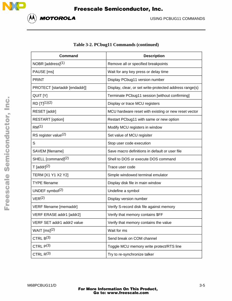


![Untitled Document [] · 2001-04-08 · – Upward compatible with M68HC11 instruction set – Interrupt stacking and programmer’s model identical to M68HC11 – 20-bit ALU – Instruction](https://static.documents.pub/doc/80x56/5e8a5d84ae965315236ff2fb/untitled-document-2001-04-08-a-upward-compatible-with-m68hc11-instruction.jpg)
![Untitled Document [cache.freescale.com]cache.freescale.com/files/microcontrollers/doc/app_note/...Order this document by AN1058/D AN1058 Reducing A/D Errors in Microcontroller Applications](https://static.documents.pub/doc/80x56/5aacff027f8b9ac55c8db80a/untitled-document-cache-cache-this-document-by-an1058d-an1058-reducing-ad.jpg)


