M789 LW 30mm HEDP Cartridge In-Bore Detonation Investigation M789 LW 30mm HEDP Cartridge In-Bore Detonation Investigation Presented By Mr. John Hirlinger, ARDEC & Dr. Scott Kukuck, ARL 26 April 2007
• M789 High Explosive Dual Purpose Cartridge– Aluminum Cartridge Case w/Electric Primer, IB52 Booster
System & Double Base WC855 Ball® Powder– High Strength 4130 Steel Projectile w/PBXN-5 Explosive Fill– Spin Compensated Shaped Charge Liner– Point Initiating, Base Detonating Nose Mounted Fuze
4
Original Incident Classifications
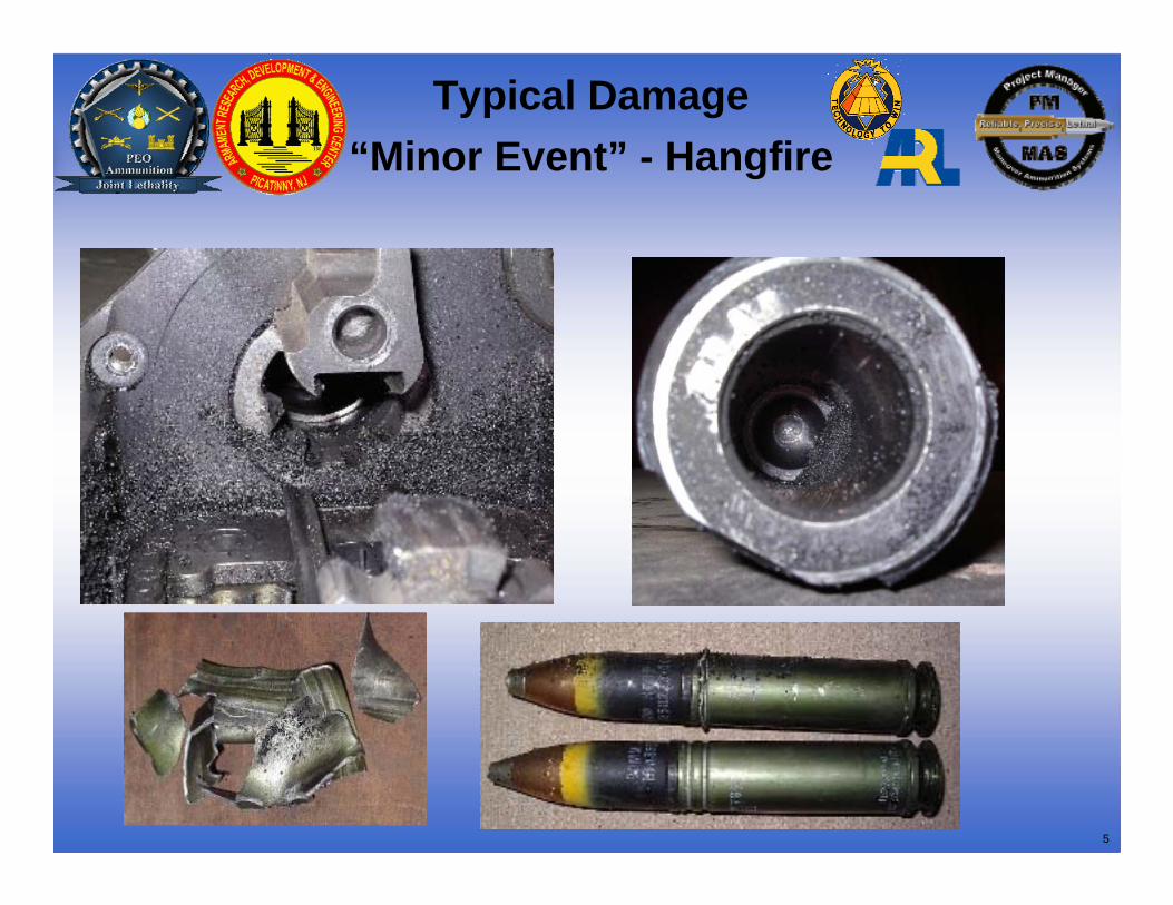
• Hangfire – Ballistic functioning of the cartridge occurs outside of the dwell time of the weapon. Operating group & sometimes receiver damaged. – 23 Incidents since Aug 97
• Inbore Detonation – Premature initiation in the barrel under the barrel support shroud. Barrel bulges, sometimes ruptures. – 21 Incidents since Aug 97
• Severed Barrel – Premature initiation in the barrel near the muzzle. Muzzle is completely lost. – 2 Incidents Since Aug 97
5
Typical Damage “Minor Event” - Hangfire
6
Typical Damage “Severe Event”- Hangfire
7
Typical Damage Inbore Detonation
• Damage Similar to or Identical to Severe Hangfire/High Pressure Plus Barrel Cracking & Muzzle Break Impacts by Fragments
TypicalExtreme
8
Typical Damage Bullet on Bullet
Severed Barrel Severed & Ruptured Barrel
1/130th 2/101st
9
In-Bore/Hang-fire Investigation Team
Participation
Boeing
Benet Labs
ATKARDEC
PM APACHE
ARL
JMCPM MAS
IHIT
In-Bore/Hang-fire Investigation Team Encompasses Elements From Across Area Weapon System, and is a Total System Approach to Solving
LW30mm Field Issues
10
IHIT Methodology
• Team Used A System Engineering And Six Sigma Approach– Interviews w/Field Units (Shooters, Ground Crews, Supply)
– Re-work Previous Root Cause Analysis for Inbore Detonations
– Use Failure Mode Effects Analysis (FMEA) Process
– Collect Data (Modeling, Simulation, Testing) To Fill Data Gaps &Populate Fault Tree For Each Failure Mode
– Conduct Design Of Experiments (DOE) And Verification Testing
– Incorporate Changes Into TDP
11
UNIT VISIT & INCIDENT KEY INFORMATION
• No Incident Resulted from the 1st Round Fired• Ammo Usually Stays in A/C Until Scheduled
Phase Maintenance - Some Units Reloaded in Reverse Order of Download
• Manual Mode for Sideloader & Uploader/Downloader are Still Used Infrequently
• Feed System Jams While Uploading are Still Occurring Resulting in Punctured Cartridge Cases
12
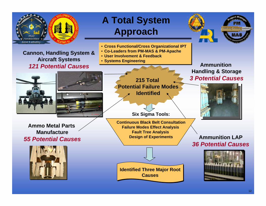
A Total System Approach
Ammunition Handling & Storage
3 Potential Causes
Ammunition LAP36 Potential Causes
Cannon, Handling System & Aircraft Systems
121 Potential Causes
Ammo Metal Parts Manufacture
55 Potential Causes
• Cross Functional/Cross Organizational IPT• Co-Leaders from PM-MAS & PM-Apache • User Involvement & Feedback• Systems Engineering
• Cross Functional/Cross Organizational IPT• Co-Leaders from PM-MAS & PM-Apache • User Involvement & Feedback• Systems Engineering
215 Total Potential Failure Modes
Identified
Identified Three Major Root Causes
Identified Three Major Root Causes
Continuous Black Belt ConsultationFailure Modes Effect Analysis
Fault Tree AnalysisDesign of Experiments
Six Sigma Tools:
13
Hangfire/High Pressure
14
Ignition System DOEPhase I
50%
Powder
Without
50%
Level 2
25%100%Propellant Level
PelletFlashtube Pellets
WithPrimary Charge
100%Booster Mix
Level 3Level 1Control Factors
Mann Barrel
PropellantBooster
PrimaryBooster & Propellant Interaction
MANN BARREL TEST
15
Damaged IB52 Pellets/Flash Tube
Normal Flash Tube Damaged IB52Open Air
High-Speed Video of
Flash Tube Venting
0
5
10
15
20
25
30
35
40
0 0.5 1 1.5 2 2.5 3
Time (ms)
Pres
sure
(MPa
)
Normal Shot #1 BreechNormal Shot #2 BreechNormal Shot #2 ProjectileNormal Cold BreechNormal Cold ProjectileNormal Hot BreechNormal Hot Projectile
WC855 in Flash Tube has Given Greater Than 40 ms Ignition
Delay
16
•DPA concentration of the 1995 Lot had depleted to half the concentration of the 2006 Lot at time = 0•AT 71°C, DPA concentration depleted to 0 within 22 days of storage
Hot Temperature Storage Led to DPA
Depletion• Over time, the original stabilizer, DPA, depletes and converts to daughter products –
2NDPA, NNODPA ; DPA reaction rate increases as temperature increasesLot 1995 Aged at 71C
0.00
0.20
0.40
0.60
0.80
1.00
1.20
Lot1995 @
71 CPull 1 -Day 4
Lot1995 @
71 CPull 2 -Day 8
Lot1995 @
71 CPull 3 -Day 13
Lot1995 @
71 CPull 4 -Day 15
Lot1995 @
71 CPull 5 -Day 19
Lot1995 @
71 CPull 6 -Day 22
Lot1995 @
71 CPull 7 -Day 25
Lot1995 @
71 CPull 8 -Day 27
Lot1995 @
71 CPull 9 -Day 29
Lot1995 @
71 CPull 10 -Day 33
% % DPA % EC % NNODPA % 2NDPA
Lot 2006 Aged at 60C
0.00
0.20
0.40
0.60
0.80
1.00
1.20
Lot 2006@ 60 CPull 1 -Day 4
Lot 2006@ 60 CPull 2 -Day 8
Lot 2006@ 60 CPull 3 -Day 13
Lot 2006@ 60 CPull 4 -Day 15
Lot 2006@ 60 CPull 5 -Day 19
Lot 2006@ 60 CPull 6 -Day 22
Lot 2006@ 60 CPull 7 -Day 25
Lot 2006@ 60 CPull 8 -Day 27
Lot 2006@ 60 CPull 9 -Day 29
Lot 2006@ 60 CPull 10 -Day 33
%
% DPA % EC
% NNODPA % 2NDPA
Lot 2006 @71C
0.00
0.20
0.40
0.60
0.80
1.00
1.20
Lot 2006@ 71 CPull 1-Day 4
Lot 2006@ 71 CPull 2 -Day 8
Lot 2006@ 71 CPull 3 -Day 13
Lot 2006@ 71 CPull 4 -Day 15
Lot 2006@ 71 CPull 5 -Day 19
Lot 2006@ 71 CPull 6 -Day 22
Lot 2006@ 71 CPull 7 -Day 25
Lot 2006@ 71 CPull 8 -Day 27
Lot 2006@ 71 CPull 9 -Day 29
Lot 2006@ 71 CPull 10 -Day 33
%
% DPA % EC
% NNODPA % 2NDPA
17
•Ballistic testing conducted at ambient. All data corrected with reference ammunition. Data is the average of 5 shots.
•Variation in pressure performance attributed to migration of DBP deterrent
Ballistic Pressure Increases With Days
Aged
Lot 2006 Aged for 34 Days at 71 C
200
250
300
350
400
450
500
0 5 10 15 20 25 30 35 40Days Aged
Pres
sure
, MPa
800
805
810
815
820
825
830
Velo
city
, m/s
Pres Mpa Vel m/s Linear (Pres Mpa)
Lot 1995 Propellant Aged for 34 Days at 71C
200
250
300
350
400
450
500
0 5 10 15 20 25 30 35 40Days Aged
Pres
sure
806808810812814816818820822824826
Velo
city
Pres Mpa Vel m/s Linear (Pres Mpa
•Within 10 days of aging a new propellant lot at 71°C, the measured pressure was in excess of the upper specification limit of 335 MPa
18
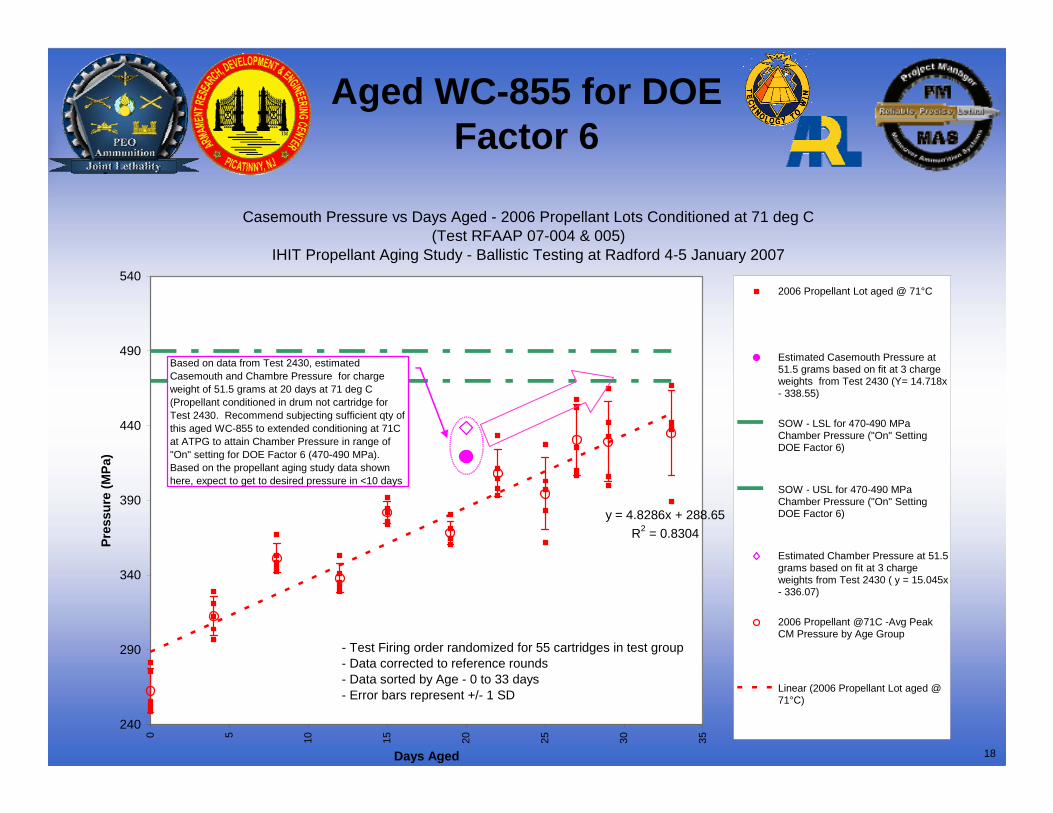
Casemouth Pressure vs Days Aged - 2006 Propellant Lots Conditioned at 71 deg C (Test RFAAP 07-004 & 005)
IHIT Propellant Aging Study - Ballistic Testing at Radford 4-5 January 2007
y = 4.8286x + 288.65R2 = 0.8304
240
290
340
390
440
490
540
0 5 10 15 20 25 30 35
Days Aged
Pres
sure
(MPa
)
2006 Propellant Lot aged @ 71°C
Estimated Casemouth Pressure at51.5 grams based on fit at 3 chargeweights from Test 2430 (Y= 14.718x- 338.55)
Estimated Chamber Pressure at 51.5grams based on fit at 3 chargeweights from Test 2430 ( y = 15.045x- 336.07)
2006 Propellant @71C -Avg PeakCM Pressure by Age Group
Linear (2006 Propellant Lot aged @71°C)
- Test Firing order randomized for 55 cartridges in test group- Data corrected to reference rounds - Data sorted by Age - 0 to 33 days - Error bars represent +/- 1 SD
Based on data from Test 2430, estimated Casemouth and Chambre Pressure for charge weight of 51.5 grams at 20 days at 71 deg C (Propellant conditioned in drum not cartridge for Test 2430. Recommend subjecting sufficient qty of this aged WC-855 to extended conditioning at 71C at ATPG to attain Chamber Pressure in range of "On" setting for DOE Factor 6 (470-490 MPa). Based on the propellant aging study data shown here, expect to get to desired pressure in <10 days
Aged WC-855 for DOE Factor 6
19
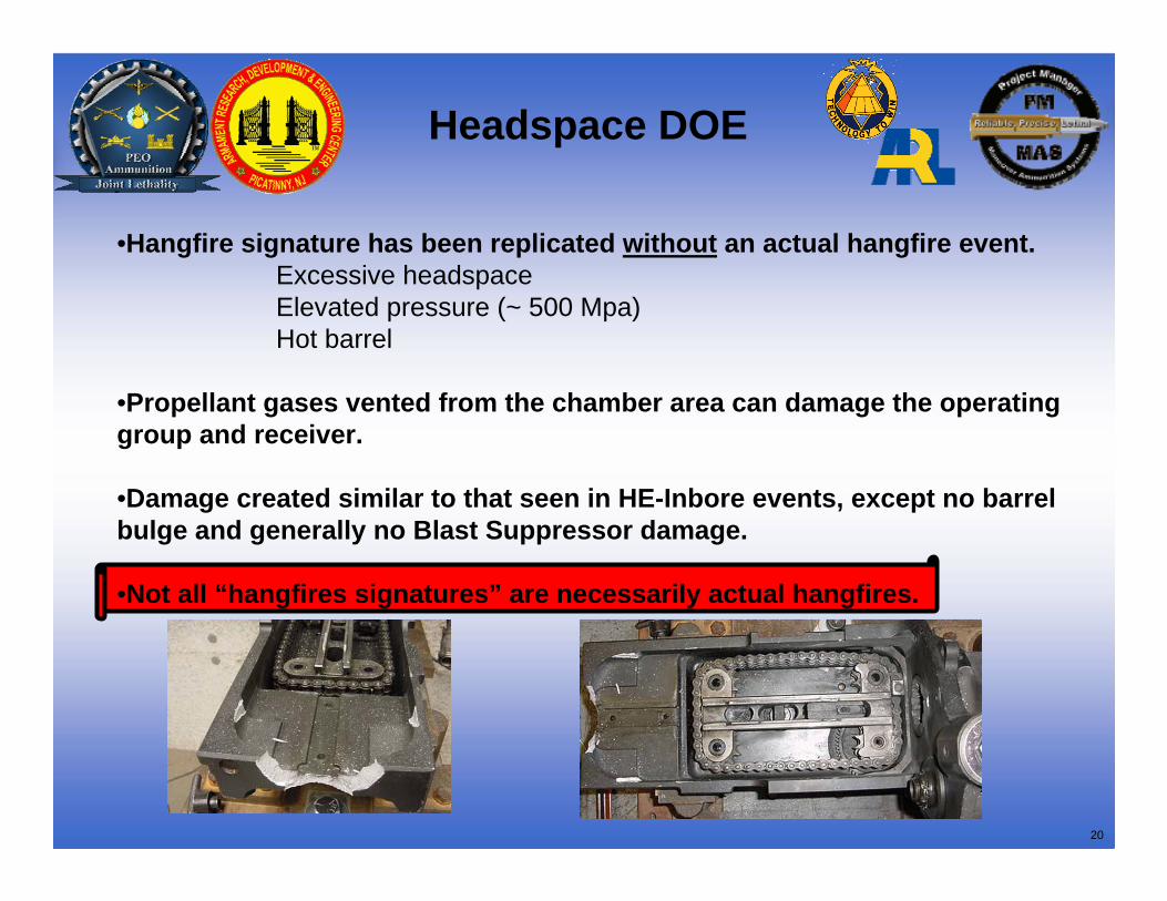
Headspace DOE
XXX58
XXX57
XXX56
XXX55
XXX54
XXX53
XXX52
XXX51
AmbientBarrel
HotBarrel (180oF)
Headspace0.031”
Headspace0.025”
NominalHeadspace
NominalPressure
HighPressure (approx
500 Mpa)
No. ofRounds
Firing Order
of Rounds
XXX58
XXX57
XXX56
XXX55
XXX54
XXX53
XXX52
XXX51
AmbientBarrel
HotBarrel (180oF)
Headspace0.031”
Headspace0.025”
NominalHeadspace
NominalPressure
HighPressure (approx
500 Mpa)
No. ofRounds
Firing Order
of Rounds
XXX52
XXX51
Am bientBarrel
M axim umHeadspace
(0.031”)
Nom inalHeadspace
(.022”)
HighPressure
(approx 415 Mpa)
No. ofRounds
Firing Orderof Rounds
XXX52
XXX51
Am bientBarrel
M axim umHeadspace
(0.031”)
Nom inalHeadspace
(.022”)
HighPressure
(approx 415 Mpa)
No. ofRounds
Firing Orderof Rounds
Phase II Test Matrix
Incident 1 Incident 2Tested ok
Phase I Test Matrix
20
•Hangfire signature has been replicated without an actual hangfire event.Excessive headspaceElevated pressure (~ 500 Mpa)Hot barrel
•Propellant gases vented from the chamber area can damage the operating group and receiver.
•Damage created similar to that seen in HE-Inbore events, except no barrel bulge and generally no Blast Suppressor damage.
•Not all “hangfires signatures” are necessarily actual hangfires.
Headspace DOE
21
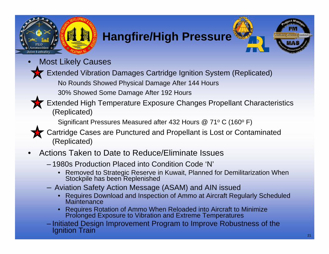
Hangfire/High Pressure
• Most Likely Causes Extended Vibration Damages Cartridge Ignition System (Replicated)
No Rounds Showed Physical Damage After 144 Hours30% Showed Some Damage After 192 Hours
Extended High Temperature Exposure Changes Propellant Characteristics (Replicated)
Significant Pressures Measured after 432 Hours @ 71o C (160o F)Cartridge Cases are Punctured and Propellant is Lost or Contaminated
(Replicated)• Actions Taken to Date to Reduce/Eliminate Issues
– 1980s Production Placed into Condition Code ‘N’ • Removed to Strategic Reserve in Kuwait, Planned for Demilitarization When
Stockpile has been Replenished– Aviation Safety Action Message (ASAM) and AIN issued
• Requires Download and Inspection of Ammo at Aircraft Regularly Scheduled Maintenance
• Requires Rotation of Ammo When Reloaded into Aircraft to Minimize Prolonged Exposure to Vibration and Extreme Temperatures
– Initiated Design Improvement Program to Improve Robustness of the Ignition Train
Notes: - Testing at ATPG 5/2/06- Casemouth pressure measured (trace#2); chamber pressure port (trace#3) n/a for this test series - Pressure values corrected based on calibration of transducer #C14607 from ATPG test data sheet.
1st in-bore
Pres
sure
(MPa
)
Time (sec)
P-t Curves from Test 2410
Location of In-Bore
6 loose fragments at 71C: 2/2 in-boresAll other conditions: 0 / 33
29
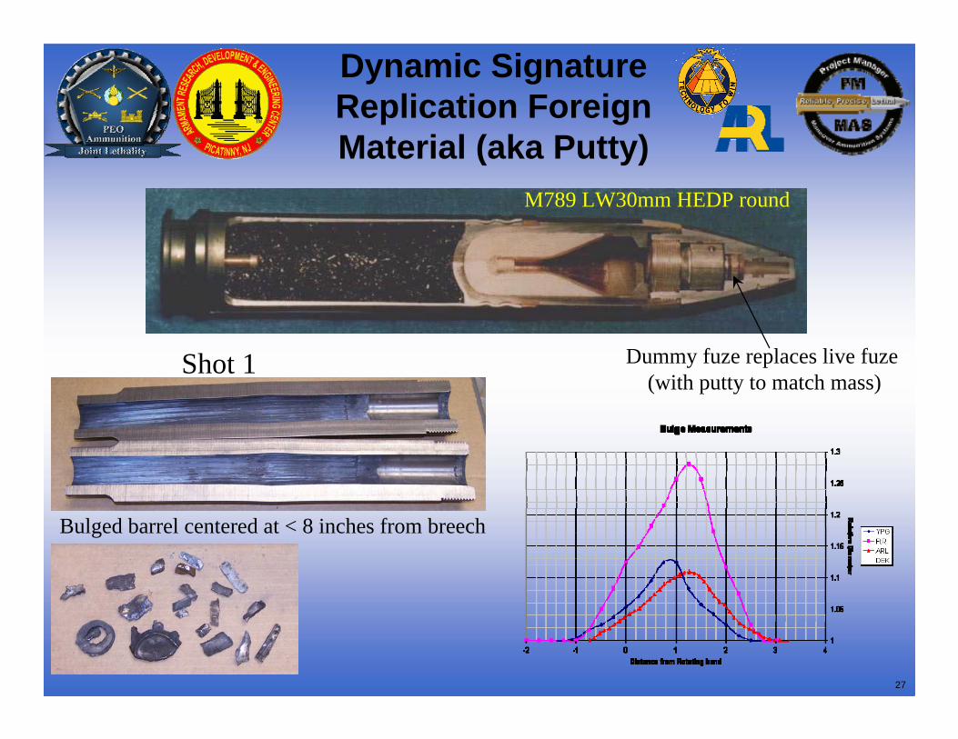
Test vs. Field Incidents -Profile
Arizona Barrel
Ft. Rucker Barrel
Test 2410
Reference Line approx. 9.5” from end of barrel
1.000
1.100
1.200
1.300
1.400
-2 -1 0 1 2 3 4
Relative Position (inch)
Rel
ativ
e D
iam
eter
FragmentsFt RuckerArizona
30
Block Reliability Prob. of Failure Final Probability Priority Ranking#504 Setback initiation due to debris in cavity 1 1.0005E-05 A1.11 1.0005E-05 In-bore demonstrated in Test 2410#65 Thin sidewall body fails on setback 1 7.8400E-07 A1.12 7.8399E-07 1 Factor 4#502 Particles embedded in HE cause HE to iniiate at setback 1 5.0000E-07 A1.15 4.9999E-07 2 Cu shaving test at High P in DOE SOWNormal projectile ? 0.9914 9.9137E-01 A2.1 4.5107E-08 3#504 Setback initiation due to debris in cavity 0.9999 1.0000E-04 A2.11 1.6300E-09 4#1 Thin BCP flange fails on setback 1 1.1000E-09 A1.17 1.1000E-09 5 Factor 2#307 Projectile Base deformed by propulsion gases 1 6.6700E-10 A1.9 6.6699E-10 6 Factor 3#303 baseplug Vibrates loose 1 3.3400E-10 A1.2 3.3399E-10 7 Factor 1#80 Cut Cartridge Case 1 1.0000E-10 A1.3 9.9998E-11 8 Factor 5#502 Particles embedded in HE cause HE to initiate at setback 1 5.0000E-06 A2.15 8.1500E-11 9Improperly secured HE moves back and detonates at setback 1 2.0000E-11 A1.16 2.0000E-11 10#65 Thin sidewall body fails on setback 1 6.4000E-07 A2.12 1.0432E-11 11PBXN-5 Develops cracks in storage #51 1 1.0001E-11 C1.1 1.0001E-11 12Voids in explosive pellet #52 1 1.0000E-11 C1.3 1.0000E-11 13
DOE FactorSpecial Purpose TestRedundant with a Prior Element Being Testing
In spec Ballistic Event 1.6345E-05 9.9998E-01 A1.1#503 High pressure event 0.9227 1.63000E-05 G2#503 Maximum pressure event 0.9985 4.55000E-08 G1
Factor 6 – Chamber Pressure G1 and G2
Propellant High Pressure (Factor 6) Cut Case (Factor 5)
Loose Base Closing Plug in Fuze(Factor 1)
Thin Sidewall due to Eccentric Cavity at Crimp Grooves (Factor 4)Thin Dome (Factor 3)
Thin Flange on Fuze Base Closing Plug (Factor 2)
Fault Tree Probabilities for In-Bore DOE
Factors
31
Main In-bore DOE
In-boresShots “on”
81*
80
80
80
5
80
~405 MPaChamber
Cut through case to proj.
body
Max Eccentricty
(~.020”)
~.05” Dome Thickness
~ .015” Flange
Thickness
~1/2 Thread Engagement
Example of “Off” Factor Setting
~480 MPaChamber
No Cut
Nominal Eccentricty
(~.008”)
~.125” Dome Thickness
~ .044” Flange Thickness
Full Thread Engagement
High Pressure
Cut Cart. Case
Eccentric Cavity
Thin Dome
Thin BCP Flange
Loose BCP
Factor
1
0
0
0
3
0
Test ResultsExample of “On” Factor Setting
0
100
200
300
400
500
0 0.5 1 1.5 2 2.5 3 3.5
Pres
sure
(MPa
)
20 days aged WC-855
0
100
200
300
400
500
0 0.5 1 1.5 2 2.5 3 3.5
Pres
sure
(MPa
)
30 days aged WC-855
* 1 shot included thin BCP Flange
32
Test In-bore Comparisons
Bar
rel D
iam
eter
(inc
hes)
Distance from End of Barrel (inches)2.530
2.550
2.570
2.590
2.610
2.630
2.650
0.0 2.0 4.0 6.0 8.0 10.0 12.0 14.0 16.0
()
Foreign MaterialThin Flange
33
P-t Curves from DOE In-bores (Thin Flange)
0
50
100
150
200
250
300
350
400
450
500
0 0.5 1 1.5 2 2.5 3
Time (msec)
Pres
sure
(MPa
)
No In-bore
In-bore #1
In-bore #2
In-bore #3(HighPressure)
Thin Flange
34
Inbore Detonation
• Most Likely Causes Foreign Material from Manufacturing Process in Liner Cavity (Replicated)Thin Flange/Spitback Crimp (Replicated)
• Actions Taken to Date to Reduce/Eliminate Issue–1980s Production Placed into Condition Code ‘N’
• Removed to Strategic Reserve in Kuwait Planned for Demilitarization When Stockpile has been Replenished
–1990+ Production• Thin Flange on Base Closing Plug Identified as a Critical Defect
– Additional Testing Added to Verify Design Margin– Double Automated Inspections Added to Manufacturing Line
• Affected Lots (Prior Inbore Detonations) Restricted from Use Until Screened• X-Ray Screening to Remove Defective Rounds Being Initiated• Manufacturing Process has been Modified to Eliminate Source of Foreign
Material–AIN & ASAM Issued to Minimize Ammo Exposure to Extreme Temperatures
35
Bullet on Bullet
36
Bullet on Bullet
A loss of propellant due to punctured case caused:1 Increased Action Time (5 to 24 ms)2 Decreased Range3 Projectiles stuck beyond origin of rifling at ~15%
propellant load 4 Projectiles stuck at origin of rifling or failed to
debullet at 5-10% propellant load.
Field Incident Stuck Projectile Test
37
Bullet on Bullet
• Most Likely Causes Cartridge Cases are Punctured and Propellant is Lost
• Efficiency Loss to a Level of 10-15% (Replicated)
• Actions Taken to Reduce/Eliminate Issue– ASAM #AH-64-07-ASAM-13 Issued
• Emphasizes Use of “Auto” Mode for D Model Apache Sideloaderwhich Minimizes Risk of Creating and Firing Punctured Cases
• Requires Download and Inspection of Ammunition at Aircraft Regularly Scheduled Maintenance
• Re-emphasizes the Need for Caution Uploading/Downloading the Aircraft to Avoid Punctured Cartridge Cases
38
Summary
• Investigation is Completed• Final Reports are Being Written for Individual as
well as Combined Efforts• Investigation Results are Being Formulated into:
– Design Changes – Manufacturing Process Changes– Stockpile, Manual and/or Procedural Changes, as