62
Mag One™ by Motorola Radio Series Basic Service Manual 6816101H01-A
| Date post: | 30-Aug-2014 |
| Category: |
Documents |
| Upload: | robinpoches |
| View: | 34 times |
| Download: | 4 times |
Mag One™ by Motorola Radio SeriesBasic Service Manual 6816101H01-A
Computer Software CopyrightsThe Motorola products described in this manual may include copyrighted Motorola computer programs stored in semiconductor memories or other media. Laws in the United States and other countries preserve for Motorola certain exclusive rights for copyrighted computer programs, including, but not limited to, the exclusive right to copy or reproduce in any form, the copyrighted computer program. Accordingly, any copyrighted Motorola computer programs contained in the Motorola products described in this manual may not be copied, reproduced, modified, reverse-engineered, or distributed in any manner without the express written permission of Motorola. Furthermore, the purchase of Motorola products shall not be deemed to grant, either directly or by implication, estoppel or otherwise, any license under the copyrights, patents or patent applications of Motorola, except for the normal non-exclusive license to use that arises by operation of law in the sale of a product.
i
DOCUMENT HISTORY
The following major changes have been implemented in this manual since the previous edition:
Edition Description Date
6816101H01-A Initial edition Mar. 2007

ii
Notes
iii
Safety InformationProduct Safety and RF Energy Exposure Booklet for Portable Two-Way Radios
The information provided in this document supersedes the general safety information contained in user guides published prior to February 2002.
RF Energy Exposure Awareness and Control Information and Operational Instructions for Occupational Use
NOTICE: This radio is intended for use in occupational/controlled conditions where users have full knowledge of their exposure and can exercise control over their exposure to meet the occupational limits in FCC and International standards. This radio device is NOT authorized for general population or consumer use.
This two-way radio uses electromagnetic energy in the radio frequency (RF) spectrum to provide communications between two or more users over a distance. It uses radio frequency (RF) energy or radio waves to send and receive calls. RF energy is one form of electromagnetic energy. Other forms include, but are not limited to, sunlight and x-rays. RF energy, however, should not be confused with these other forms of electromagnetic energy, which when used improperly, can cause biological damage. Very high levels of x-rays, for example, can damage tissues and genetic material.
Experts in science, engineering, medicine, health, and industry work with organizations to develop standards for safe exposure to RF energy. These standards provide recommended levels of RF exposure for both workers and the general public. These recommended RF exposure levels include substantial margins of protection.
All Motorola two-way radios are designed, manufactured, and tested to ensure they meet government-established RF exposure levels. In addition, manufacturers also recommend specific operating instructions to users of two-way radios. These instructions are important because they inform users about RF energy exposure and provide simple procedures on how to control it.
Please refer to the following websites for more information on what RF energy exposure is and how to control your exposure to assure compliance with established RF exposure limits: http://www.fcc.gov/oet/rfsafety/rf-faqs.html http://www.osha.gov/SLTC/radiofrequencyradiation/index.html
Federal Communication Commission (FCC) Regulations
The FCC rules require manufacturers to comply with the FCC RF energy exposure limits for portable two-way radios before they can be marketed in the U.S. When two-way radios are used as a consequence of employment, the FCC requires users to be fully aware of and able to control their exposure to meet occupational requirements.
BEFORE USING THIS RADIO, READ THE FOLLOWING INFORMATION WHICH CONTAINS IMPORTANT OPERATING INSTRUCTIONS FOR SAFE USAGE AND RF ENERGY AWARENESS AND CONTROL INFORMATION AND OPERATIONAL INSTRUCTIONS FOR COMPLIANCE WITH RF ENERGY EXPOSURE LIMITS IN APPLICABLE NATIONAL AND INTERNATIONAL STAN-DARDS. ALSO READ THE OPERATIONAL INSTRUCTIONS FOR SAFE USAGE. FOR RADIOS THAT HAVE BEEN APPROVED AS INTRINSICALLY SAFE, READ THE INSTRUCTIONS AND INFORMATION ON INTRINSIC SAFETY ON PAGE vii.
iv
Exposure awareness can be facilitated by the use of a product label directing users to specific user awareness information. Your Motorola two-way radio has a RF exposure product label. Also, your Motorola user manual, or separate safety booklet includes information and operating instructions required to control your RF exposure and to satisfy compliance requirements.
Compliance with RF Exposure Standards
Your Motorola two-way radio is designed and tested to comply with a number of national and International standards and guidelines (listed below) for human exposure to radio frequency electromagnetic energy. This radio complies with the IEEE (FCC) and ICNIRP exposure limits for occupational/controlled RF exposure environments at operating duty factors of up to 50% talk-50% listen and is authorized by the FCC for occupational use only.
In terms of measuring RF energy for compliance with these exposure guidelines, your radio generates measurable RF energy only while it is transmitting (during talking), not when it is receiving (listening) or in standby mode.
NOTE: The approved batteries, supplied with this radio, are rated for a 5-5-90 duty factor (5% talk-5% listen-90% standby) even though this radio complies with FCC occupational exposure limits and may operate at duty factors of up to 50% talk.
Your Motorola two-way radio complies with the following RF energy exposure standards and guidelines:
• United States Federal Communications Commission, Code of Federal Regulations; 47CFR part 2 sub-part J
• American National Standards Institute (ANSI) / Institute of Electrical and Electronic Engineers (IEEE) C95. 1-1992
• Institute of Electrical and Electronic Engineers (IEEE) C95.1-1999 Edition• International Commission on Non-Ionizing Radiation Protection (ICNIRP) 1998• Ministry of Health (Canada) Safety Code 6. Limits of Human Exposure to Radiofrequency Elec-
tromagnetic Fields in the Frequency Range from 3 kHz to 300 GHz, 1999• Australian Communications Authority Radiocommunications (Electromagnetic Radiation -
Human Exposure) Standard, 2003• ANATEL ANNEX to Resolution No. 303 of July 2, 2002 "Regulation of limitation of exposure to
electrical, magnetic and electromagnetic fields in the radio frequency range between 9 KHz and 300 GHz" and "Attachment to resolution # 303 from July 2, 2002" "Additional Requirements for SMR, Cellular and PCS Product Certification"
RF Exposure Compliance and Control Guidelines and Operating Instructions
To control your exposure and ensure compliance with the occupational/controlled environment exposure limits, always adhere to the following procedures.
Guidelines:• Do not remove the RF Exposure Label from the device.• User awareness instructions should accompany device when transferred to other users.• Do not use this device if the operational requirements described herein are not met.
v
Operating Instructions• Transmit no more than the rated duty factor of 50% of the time. To transmit (talk), push the Push-
To-Talk (PTT) button. To receive calls, release the PTT button. Transmitting 50% of the time, or less, is important because this radio generates measurable RF energy exposure only when transmitting (in terms of measuring for standards compliance).
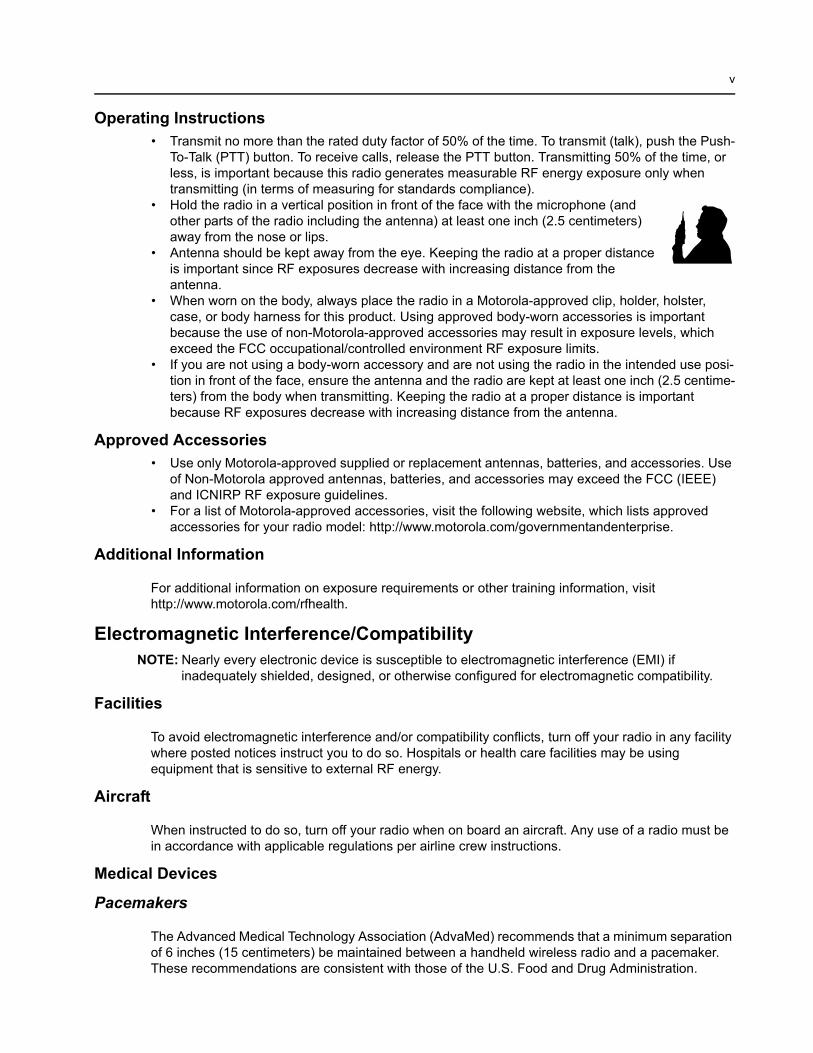
• Hold the radio in a vertical position in front of the face with the microphone (and other parts of the radio including the antenna) at least one inch (2.5 centimeters) away from the nose or lips.
• Antenna should be kept away from the eye. Keeping the radio at a proper distance is important since RF exposures decrease with increasing distance from the antenna.
• When worn on the body, always place the radio in a Motorola-approved clip, holder, holster, case, or body harness for this product. Using approved body-worn accessories is important because the use of non-Motorola-approved accessories may result in exposure levels, which exceed the FCC occupational/controlled environment RF exposure limits.
• If you are not using a body-worn accessory and are not using the radio in the intended use posi-tion in front of the face, ensure the antenna and the radio are kept at least one inch (2.5 centime-ters) from the body when transmitting. Keeping the radio at a proper distance is important because RF exposures decrease with increasing distance from the antenna.
Approved Accessories• Use only Motorola-approved supplied or replacement antennas, batteries, and accessories. Use
of Non-Motorola approved antennas, batteries, and accessories may exceed the FCC (IEEE) and ICNIRP RF exposure guidelines.
• For a list of Motorola-approved accessories, visit the following website, which lists approved accessories for your radio model: http://www.motorola.com/governmentandenterprise.
Additional Information
For additional information on exposure requirements or other training information, visit http://www.motorola.com/rfhealth.
Electromagnetic Interference/CompatibilityNOTE: Nearly every electronic device is susceptible to electromagnetic interference (EMI) if
inadequately shielded, designed, or otherwise configured for electromagnetic compatibility.
Facilities
To avoid electromagnetic interference and/or compatibility conflicts, turn off your radio in any facility where posted notices instruct you to do so. Hospitals or health care facilities may be using equipment that is sensitive to external RF energy.
Aircraft
When instructed to do so, turn off your radio when on board an aircraft. Any use of a radio must be in accordance with applicable regulations per airline crew instructions.
Medical Devices
Pacemakers
The Advanced Medical Technology Association (AdvaMed) recommends that a minimum separation of 6 inches (15 centimeters) be maintained between a handheld wireless radio and a pacemaker. These recommendations are consistent with those of the U.S. Food and Drug Administration.
vi
Persons with pacemakers should:
• ALWAYS keep the radio more than 6 inches (15 centimeters) from their pacemaker when the radio is turned ON.
• Not carry the radio in the breast pocket.• Use the ear opposite the pacemaker to minimize the potential for interference.• Turn the radio OFF immediately if there is any reason to suspect that interference is taking place.
Hearing Aids
Some digital wireless radios may interfere with some hearing aids. In the event of such interference, you may want to consult your hearing aid manufacturer to discuss alternatives.
Other Medical Devices
If you use any other personal medical device, consult the manufacturer of your device to determine if it is adequately shielded from RF energy. Your physician may be able to assist you in obtaining this information.
Use of communication devices while driving
Always check the laws and regulations on the use of radios in the areas where you drive.
• Give full attention to driving and to the road.• Use hands-free operation, if available.• Pull off the road and park before making or answering a call, if driving conditions or regulations
so require.
Operational Warnings
For vehicle with air bagsRefer to vehicle manufacturer's manual prior to installation of electronic equipment to avoid interference with air bag wiring.Do not place a portable radio in the area over an air bag or in the air bag deployment area. Air bags inflate with great force. If a portable radio is placed in the air bag deployment area and the air bag inflates, the radio may be propelled with great force and cause serious injury to occupants of the vehicle.Potentially Explosive Atmospheres(Explosive atmospheres refers to hazard classified locations that may contain hazardous gas, vapors, or dusts.)Turn off your radio prior to entering any area with a potentially explosive atmosphere unless it is a portable radio type especially qualified for use in such areas as Intrinsically Safe (for example, Factory Mutual, CSA, UL, or CENELEC).Do not remove, install, or charge batteries in such areas. Sparks in a potentially explosive atmosphere can cause an explosion or fire resulting in bodily injury or even death.The areas with potentially explosive atmospheres referred to above include fueling areas such as below decks on boats, fuel or chemical transfer or storage facilities, and areas where the air contains chemicals or particles such as grain, dust or metal powders. Areas with potentially explosive atmospheres are often, but not always, posted.Blasting Caps And Blasting AreasTo avoid possible interference with blasting operations, turn off your radio when you are near electrical blasting caps, in a blasting area, or in areas posted: "Turn off two-way radio." Obey all signs and instructions.
vii
Operational Cautions
Intrinsically Safe Radio Information
The Intrinsically safe approval unit refers to a product that has been approved as intrinsically safe by an approval agency (for example FM Approvals, CSA, UL, or Cenelec) and certifies that a particular product meets the Agency's applicable intrinsic safety standards for specific types of hazardous classified locations. A portable radio that has been approved for intrinsic safety will have Approval label attached to the radio to identify the unit as being Approved for specified hazardous atmospheres. This label specifies the hazardous Class/Division/Group along with the part number of the battery that must be used. The intrinsically safe approval label will be located on the portable radio unit.
Operational Cautions for Intrinsic Safe Equipment
Warnings for Radios Approved as Intrinsically Safe
Radios must ship from the Motorola manufacturing facility with the hazardous atmosphere capability and the intrinsic safety approval labelling (FM, UL, CSA, CENELEC). Radios will not be upgraded to this capability and labeled once they have been shipped to the field.
AntennasDo not use any portable radio that has a damaged antenna. If a damaged antenna comes into contact with your skin, a minor burn can result.
BatteriesAll batteries can cause property damage and/or bodily injury, such as burns, if a conductive material such as jewelry, keys, or beaded chains touches exposed terminals. The conductive material may complete an electrical circuit (short circuit) and become quite hot. Exercise care in handling any charged battery, particularly when placing it inside a pocket, purse, or other container with metal objects.
• Do not operate radio communications equipment in a hazardous atmosphere unless it is a type especially qualified (for example, FM, UL, CSA, or CENELEC approved). An explosion or fire may result.
• Do not operate a radio unit that has been approved as intrinsically safe product in a hazardous atmosphere if it has been physically damaged (for example, cracked housing). An explosion or fire may result.
• Do not replace or charge batteries in a hazardous atmosphere. Contact sparking may occur while installing or removing batteries and cause an explosion or fire.
viii
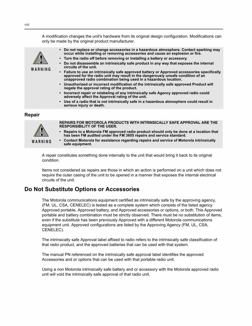
A modification changes the unit's hardware from its original design configuration. Modifications can only be made by the original product manufacturer.
Repair
A repair constitutes something done internally to the unit that would bring it back to its original condition.
Items not considered as repairs are those in which an action is performed on a unit which does not require the outer casing of the unit to be opened in a manner that exposes the internal electrical circuits of the unit.
Do Not Substitute Options or Accessories
The Motorola communications equipment certified as intrinsically safe by the approving agency, (FM, UL, CSA, CENELEC) is tested as a complete system which consists of the listed agency Approved portable, Approved battery, and Approved accessories or options, or both. This Approved portable and battery combination must be strictly observed. There must be no substitution of items, even if the substitute has been previously Approved with a different Motorola communications equipment unit. Approved configurations are listed by the Approving Agency (FM, UL, CSA, CENELEC).
The intrinsically safe Approval label affixed to radio refers to the intrinsically safe classification of that radio product, and the approved batteries that can be used with that system.
The manual PN referenced on the intrinsically safe approval label identifies the approved Accessories and or options that can be used with that portable radio unit.
Using a non Motorola intrinsically safe battery and or accessory with the Motorola approved radio unit will void the intrinsically safe approval of that radio unit.
• Do not replace or change accessories in a hazardous atmosphere. Contact sparking may occur while installing or removing accessories and cause an explosion or fire.
• Turn the radio off before removing or installing a battery or accessory.• Do not disassemble an intrinsically safe product in any way that exposes the internal
circuits of the unit.• Failure to use an intrinsically safe approved battery or Approved accessories specifically
approved for the radio unit may result in the dangerously unsafe condition of an unapproved radio combination being used in a hazardous location.
• Unauthorized or incorrect modification of the intrinsically safe approved Product will negate the approval rating of the product.
• Incorrect repair or relabeling of any intrinsically safe Agency approved radio could adversely affect the Approval rating of the unit.
• Use of a radio that is not intrinsically safe in a hazardous atmosphere could result in serious injury or death.
REPAIRS FOR MOTOROLA PRODUCTS WITH INTRINSICALLY SAFE APPROVAL ARE THE RESPONSIBILITY OF THE USER.• Repairs to a Motorola FM approved radio product should only be done at a location that
has been FM audited under the FM 3605 repairs and service standard.• Contact Motorola for assistance regarding repairs and service of Motorola intrinsically
safe equipment.
Table of ContentsDocument History..............................................................................................i
Safety Information ........................................................................................... iii
Section 1 INTRODUCTION
1.0 Scope of Manual....................................................................................................1-12.0 Warranty and Service Support...............................................................................1-1
2.1 Warranty Period and Return Instructions ........................................................1-12.2 After Warranty Period......................................................................................1-22.3 Piece Parts ......................................................................................................1-22.4 Technical Support ...........................................................................................1-22.5 Further Assistance From Motorola ..................................................................1-2
3.0 Radio Model Information........................................................................................1-34.0 Radio Features .....................................................................................................1-4
Section 2 MAINTENANCE
1.0 Introduction ............................................................................................................2-12.0 Preventive Maintenance ........................................................................................2-1
2.1 Inspection ........................................................................................................2-12.2 Cleaning Procedures.......................................................................................2-1
3.0 Safe Handling of CMOS and LDMOS Devices......................................................2-24.0 Repair Procedures and Techniques — General ....................................................2-35.0 Disassembling and Reassembling the Radio — General ......................................2-46.0 Radio Disassembly — Detailed .............................................................................2-5
6.1 Front Cover from Chassis Disassembly ..........................................................2-56.2 PC Board Disassembly ...................................................................................2-8
7.0 Radio Reassembly — Detailed..............................................................................2-87.1 PC Board Reassembly ....................................................................................2-87.2 Chassis and Front Cover Reassembly ...........................................................2-9
8.0 Mechanical View and Parts List ...........................................................................2-128.1 Exploded View and Parts List........................................................................2-12
9.0 Service Aids.........................................................................................................2-1610.0 Test Equipment....................................................................................................2-1711.0 Programming Cable (PMDN4043_R) ..................................................................2-1712.0 Cloning Cable (PMDN4060_R)............................................................................2-1813.0 Test Box (PMDN4040_R) ....................................................................................2-18
Section 3 RADIO TUNING
1.0 Introduction ............................................................................................................3-12.0 Hardware Tuning Setup and Procedure ................................................................3-2
2.1 Tuning Frequency ..........................................................................................3-22.2 Preparation Before Tuning (refer to Figure 3-1) ..............................................3-22.3 Transmitter Tuning ..........................................................................................3-32.4 Receiver Tuning ..............................................................................................3-6
Section 4 RADIO PROGRAMMING
1.0 Introduction ............................................................................................................4-12.0 Programming Your Radio ......................................................................................4-1
2.1 Overview of the Programming Process...........................................................4-12.2 Cloning Radio Parameters to User Radios .....................................................4-12.3 Parameters which are cloned..........................................................................4-12.4 Parameters which are not cloned....................................................................4-12.5 To Clone a Radio ............................................................................................4-12.6 Error Conditions ..............................................................................................4-2
3.0 CPS Programming.................................................................................................4-23.1 To Read Radio Data to a PC...........................................................................4-33.2 To Write Data to a Radio.................................................................................4-3
4.0 Factory Reset ........................................................................................................4-3
Section 5 ACCESSORIES
1.0 Antennas................................................................................................................5-12.0 Carry Accessories..................................................................................................5-13.0 Carry Cases...........................................................................................................5-14.0 Chargers ................................................................................................................5-15.0 Batteries.................................................................................................................5-16.0 Audio Accessories .................................................................................................5-27.0 Publications ...........................................................................................................5-28.0 Service Kits............................................................................................................5-2
Section 6 MODEL CHART AND TEST SPECIFICATION
1.0 VHF Band 1 Information (136–150 MHz) .............................................................6-12.0 Specifications.........................................................................................................6-23.0 VHF Band 2 Information (150 – 174 MHz) ...........................................................6-34.0 Specifications.........................................................................................................6-45.0 UHF Band 1 Information (403-425MHz) ...............................................................6-56.0 Specifications.........................................................................................................6-67.0 UHF Band 2 Information (450 – 470MHz) ............................................................6-78.0 Specifications.........................................................................................................6-89.0 UHF Band 4 Information (490 - 512 MHz) ............................................................6-910.0 Specifications.......................................................................................................6-10
Glossary of Terms........................................................................................G-1
Scope of Manual 1-1
Section 1
INTRODUCTION
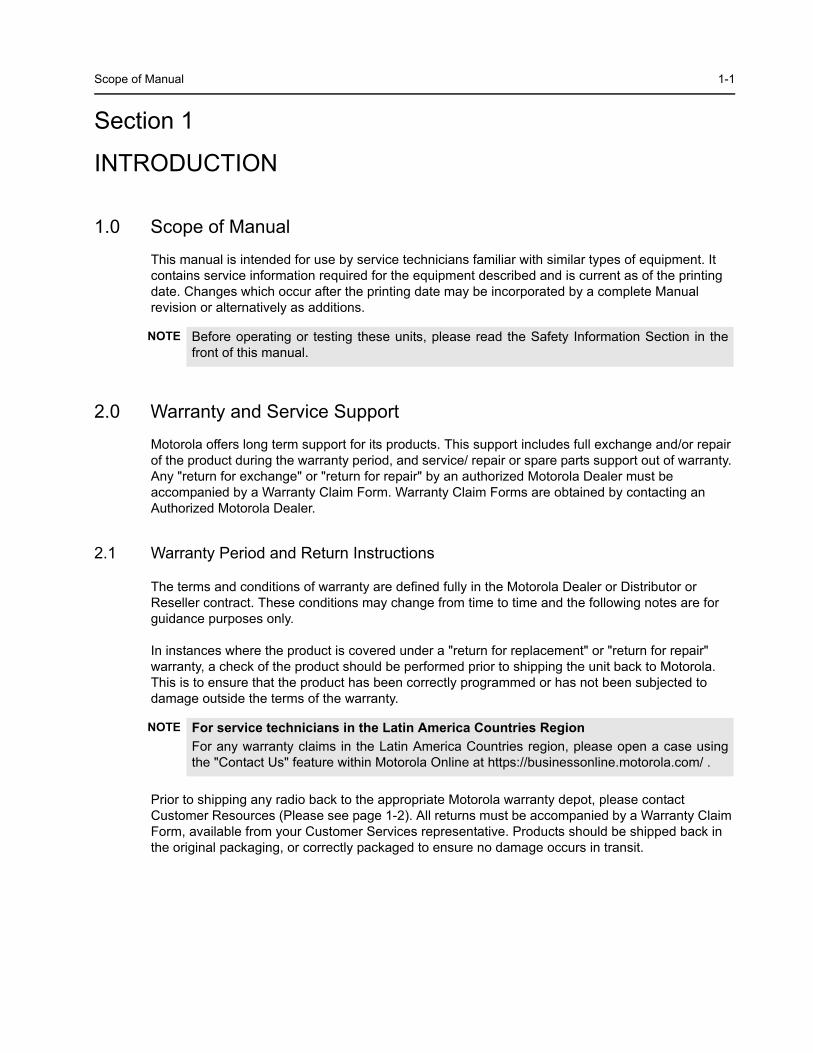
1.0 Scope of Manual
This manual is intended for use by service technicians familiar with similar types of equipment. It contains service information required for the equipment described and is current as of the printing date. Changes which occur after the printing date may be incorporated by a complete Manual revision or alternatively as additions.
2.0 Warranty and Service Support
Motorola offers long term support for its products. This support includes full exchange and/or repair of the product during the warranty period, and service/ repair or spare parts support out of warranty. Any "return for exchange" or "return for repair" by an authorized Motorola Dealer must be accompanied by a Warranty Claim Form. Warranty Claim Forms are obtained by contacting an Authorized Motorola Dealer.
2.1 Warranty Period and Return Instructions
The terms and conditions of warranty are defined fully in the Motorola Dealer or Distributor or Reseller contract. These conditions may change from time to time and the following notes are for guidance purposes only.
In instances where the product is covered under a "return for replacement" or "return for repair" warranty, a check of the product should be performed prior to shipping the unit back to Motorola. This is to ensure that the product has been correctly programmed or has not been subjected to damage outside the terms of the warranty.
Prior to shipping any radio back to the appropriate Motorola warranty depot, please contact Customer Resources (Please see page 1-2). All returns must be accompanied by a Warranty Claim Form, available from your Customer Services representative. Products should be shipped back in the original packaging, or correctly packaged to ensure no damage occurs in transit.
NOTE Before operating or testing these units, please read the Safety Information Section in the front of this manual.
NOTE For service technicians in the Latin America Countries RegionFor any warranty claims in the Latin America Countries region, please open a case using the "Contact Us" feature within Motorola Online at https://businessonline.motorola.com/ .
1-2 Warranty and Service Support
2.2 After Warranty Period
After the Warranty period, Motorola continues to support its products in two ways.
1. Motorola's Managed Technical Services (MTS) offers a repair service to both end users and dealers at competitive prices.
2. MTS supplies individual parts and modules that can be purchased by dealers who are techni-cally capable of performing fault analysis and repair.
2.3 Piece Parts
Some replacement parts, spare parts, and/or product information can be ordered directly. If a complete Motorola part number is assigned to the part, it is available from Motorola’s Managed Technical Services (MTS). If no part number is assigned, the part is not normally available from Motorola. If the part number is appended with an asterisk, the part is serviceable by Motorola Depot only. If a parts list is not included, this generally means that no user-serviceable parts are available for that kit or assembly.
All orders for parts/information should include the complete Motorola identification number. All part orders should be directed to your local MTS office. Please refer to your latest price pages.
2.4 Technical Support
Technical support is available to assist the dealer/distributor in resolving any malfunction which may be encountered. Initial contact should be by telephone wherever possible. When contacting Motorola Technical Support, be prepared to provide the product model number and the unit’s serial number.
2.5 Further Assistance From Motorola
You can also contact the Customer Help Desk through the following web address: http://www.motorola.com/governmentandenterprise/contactus
NOTE For service technicians in the Latin America Countries RegionAfter Warranty Period claims in the Latin America Countries region are handled through the Motorola Authorized Service Provider (SAM) Network. To find the nearest SAM, please go to Motorola Resource Center in Motorola Online at https://businessonline.motorola.com/ .
NOTE For service technicians in the Latin America Countries RegionAll part orders should be directed to your local Parts Distributors.
NOTE For service technicians in the Latin America Countries RegionFor Technical Support in the Latin America Countries Region, please open a case using the "Contact Us" feature within Motorola Online at https://businessonline.motorola.com/ .
NOTE Only Motorola Service Centers or Approved Motorola Service Dealers can perform these functions. Any tampering by non-authorized Motorola Service Centers voids the warranty of your radio. To find out more about Motorola and its approved Service Centers, please visit http://www.motorola.com/governmentandenterprise/public/functions/home/home.aspx
Radio Model Information 1-3
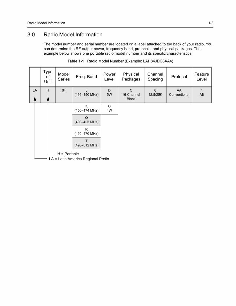
3.0 Radio Model Information
The model number and serial number are located on a label attached to the back of your radio. You can determine the RF output power, frequency band, protocols, and physical packages. The example below shows one portable radio model number and its specific characteristics.
Table 1-1 Radio Model Number (Example: LAH84JDC8AA4)
Type of
Unit
Model Series Freq. Band Power
LevelPhysical
PackagesChannel Spacing Protocol Feature
Level
LA H 84 J(136–150 MHz)
D5W
C16-Channel
Black
812.5/25K
AAConventional
4A8
K(150–174 MHz)
C4W
Q(403–425 MHz)
R(450–470 MHz)
T(490–512 MHz)
LA = Latin America Regional PrefixH = Portable
1-4 Radio Features
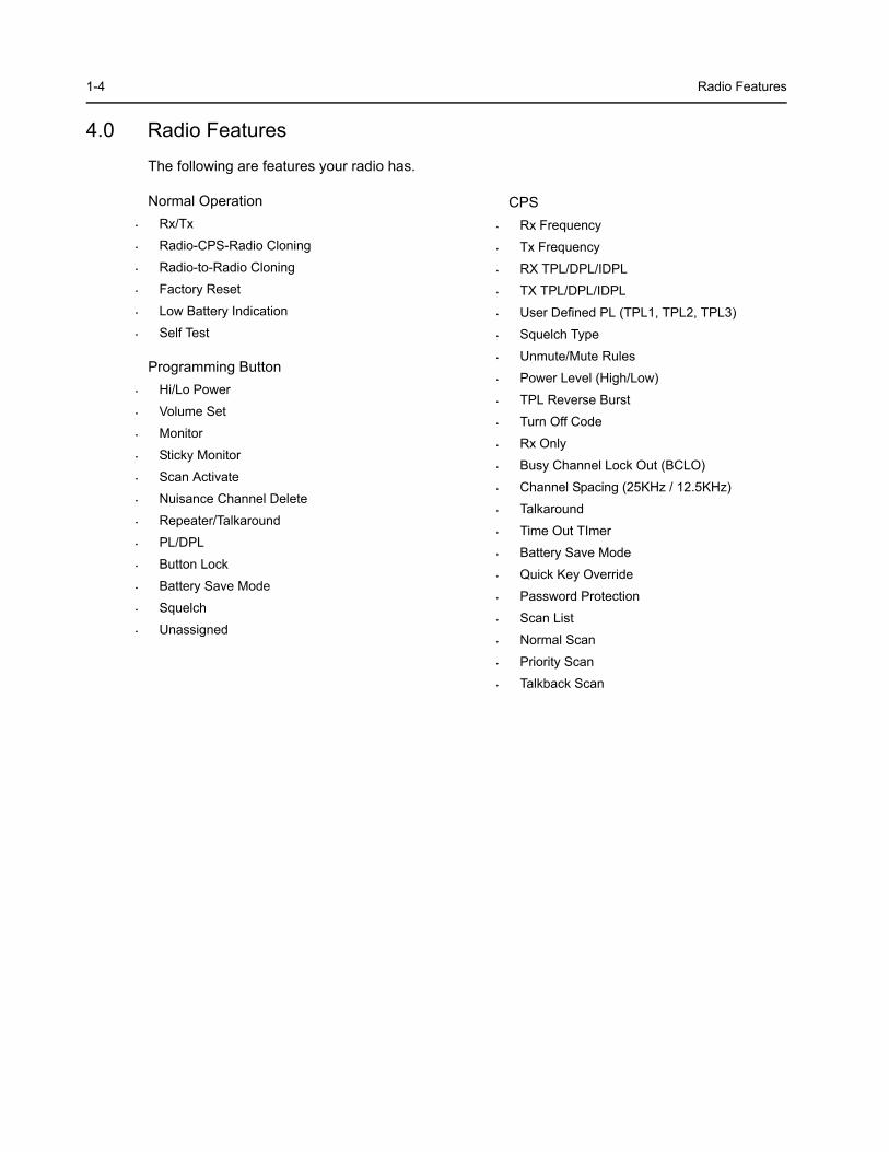
4.0 Radio Features
The following are features your radio has.
Normal Operation• Rx/Tx
• Radio-CPS-Radio Cloning
• Radio-to-Radio Cloning
• Factory Reset
• Low Battery Indication
• Self Test
Programming Button• Hi/Lo Power
• Volume Set
• Monitor
• Sticky Monitor
• Scan Activate
• Nuisance Channel Delete
• Repeater/Talkaround
• PL/DPL
• Button Lock
• Battery Save Mode
• Squelch
• Unassigned
CPS• Rx Frequency
• Tx Frequency
• RX TPL/DPL/IDPL
• TX TPL/DPL/IDPL
• User Defined PL (TPL1, TPL2, TPL3)
• Squelch Type
• Unmute/Mute Rules
• Power Level (High/Low)
• TPL Reverse Burst
• Turn Off Code
• Rx Only
• Busy Channel Lock Out (BCLO)
• Channel Spacing (25KHz / 12.5KHz)
• Talkaround
• Time Out TImer
• Battery Save Mode
• Quick Key Override
• Password Protection
• Scan List
• Normal Scan
• Priority Scan
• Talkback Scan
2-1
Section 2
MAINTENANCE
1.0 Introduction
This chapter provides details about the following:
• Preventive Maintenance• Safe Handling of CMOS and LDMOS Devices• General Repair Procedures and Techniques• Disassembling and Reassembling the Radio
2.0 Preventive Maintenance
Periodic visual inspection and cleaning is recommended.
2.1 Inspection
Check that the external surfaces of the radio are clean, and that all external controls and switches are functional. It is not recommended to inspect the interior electronic circuitry.
2.2 Cleaning Procedures
The following procedures describe the recommended cleaning agents and the methods to be used when cleaning the external and internal surfaces of the radio. External surfaces include the front cover, housing assembly and battery case. These surfaces should be cleaned whenever a periodic visual inspection reveals the presence of smudges, grease, and/or grime.
The only recommended agent for cleaning the external radio surfaces is a 0.5% solution of a mild dishwashing detergent in water. The only factory recommended liquid for cleaning the printed circuit boards and their components is isopropyl alcohol (70% by volume).
Cleaning External Plastic Surfaces
Apply the 0.5% detergent-water solution sparingly with a stiff, non-metallic, short-bristled brush to work all loose dirt away from the radio. Use a soft, absorbent, lintless cloth or tissue to remove the solution and dry the radio. Make sure that no water remains entrapped near the connectors, cracks, or crevices.
NOTE Internal surfaces should be cleaned only when the radio is disassembled for service or repair.
CAUTION: The effects of certain chemicals and their vapors can have harmful results on certain plastics. Avoid using aerosol sprays, tuner cleaners, and other chemicals.
2-2 Safe Handling of CMOS and LDMOS Devices
Cleaning Internal Circuit Boards and Components
Isopropyl alcohol (70%) may be applied with a stiff, non-metallic, short-bristled brush to dislodge embedded or caked materials located in hard-to-reach areas. The brush stroke should direct the dislodged material out and away from the inside of the radio. Make sure that controls or tunable components are not soaked with alcohol. Do not use high-pressure air to hasten the drying process since this could cause the liquid to collect in unwanted places. After completing of the cleaning process, use a soft, absorbent, lintless cloth to dry the area. Do not brush or apply any isopropyl alcohol to the frame, front cover, or back cover.
3.0 Safe Handling of CMOS and LDMOS Devices
Complementary metal-oxide semiconductor (CMOS) devices are used in this family of radios, and are susceptible to damage by electrostatic or high voltage charges. Damage can be latent, resulting in failures occurring weeks or months later. Therefore, special precautions must be taken to prevent device damage during disassembly, troubleshooting, and repair.
Handling precautions are mandatory for CMOS circuits and are especially important in low humidity conditions. DO NOT attempt to disassemble the radio without first referring to the following CAUTION statement.
NOTE Always use a fresh supply of alcohol and a clean container to prevent contamination by dissolved material (from previous usage).
CAUTION: This radio contains static-sensitive devices. Do not open the radio unless you are properly grounded. Take the following precautions when working on this unit:
• Store and transport all CMOS devices in conductive material so that all exposed leads are shorted together. Do not insert CMOS devices into conventional plastic “snow” trays used for storage and transportation of other semiconductor devices.
• Ground the working surface of the service bench to protect the CMOS device. We recommend using the Motorola Static Protection Assembly (part number 0180386A82), which includes a wrist strap, two ground cords, a table mat, and a floor mat.
• Wear a conductive wrist strap in series with a 100k resistor to ground. (Replacement wrist straps that connect to the bench top covering are Motorola part number RSX-4015.)
• Do not wear nylon clothing while handling CMOS devices.• Do not insert or remove CMOS devices with power applied. Check all power supplies used for
testing CMOS devices to be certain that there are no voltage transients present.• When straightening CMOS pins, provide ground straps for the apparatus used.• When soldering, use a grounded soldering iron.• If at all possible, handle CMOS devices by the package and not by the leads. Prior to touching
the unit, touch an electrical ground to remove any static charge that you may have accumulated. The package and substrate may be electrically common. If so, the reaction of a discharge to the case would cause the same damage as touching the leads.
Repair Procedures and Techniques — General 2-3
4.0 Repair Procedures and Techniques — General
Parts Replacement and Substitution
When damaged parts are replaced, identical parts should be used. If the identical replacement part is not locally available, check the parts list for the proper Motorola part number and order the part from the nearest Motorola Communications parts center listed in the Piece Parts section of this manual.
Rigid Circuit Boards
This family of radios uses bonded, multi-layer, printed circuit boards. Since the inner layers are not accessible, some special considerations are required when soldering and unsoldering components. The printed-through holes may interconnect multiple layers of the printed circuit. Therefore, exercise care to avoid pulling the plated circuit out of the hole.
When soldering near the 20-pin and 40-pin connectors:
• Avoid accidentally getting solder in the connector. • Be careful not to form solder bridges between the connector pins. • Examine your work closely for shorts due to solder bridges.
Flexible Circuits
The flexible circuits are made from a different material than the rigid boards, and require different soldering techniques. Excessive prolonged heat on a flexible circuit can damage the material. Therefore, avoid excessive heat and excessive bending.
For parts replacement, use the ST-1087 Temperature-Controlled Solder Station with a 600-700 degree F tip, and use small diameter solder such as ST-633. The smaller size solder will melt faster and require less heat to be applied to the circuit.
To replace a component on a flexible circuit:
1. Grasp with seizers (hemostats) the edge of the flexible circuit near the part to be removed. 2. Pull gently.3. Apply the tip of the soldering iron to the component connections while pulling with the seizers.
Chip Components
Use either the RLN-4062 Hot-Air Repair Station or the Motorola 0180381B45 Repair Station for chip component replacement. When using the 0180381B45 Repair Station, select the TJ-65 mini-thermojet hand piece. On either unit, adjust the temperature control to 700 degrees F. (370 degrees C), and adjust the airflow to a minimum setting. Airflow can vary due to component density.
• To remove a chip component, select a hot-air hand piece and position the nozzle of the hand piece approximately 1/8” above the component to be removed. Begin applying the hot air. Once the solder reflows, remove the component using a pair of tweezers. Using solder wick and a soldering iron or a power desoldering station, remove the excess solder from the pads.
NOTE Do not attempt to puddle-out components. Prolonged application of heat may damage the flexible circuit.
2-4 Disassembling and Reassembling the Radio — General
• To replace a chip component using a soldering iron, select the appropriate micro-tipped soldering iron and apply fresh solder to one of the solder pads. Using a pair of tweezers, position the new chip component in place while heating the fresh solder. Once solder wicks onto the new component, remove the heat from the solder. Heat the remaining pad with the soldering iron and apply solder until it wicks to the component. If necessary, touch up the first side. All solder joints should be smooth and shiny.
• To replace a chip component using hot air, select the hot-air hand piece and reflow the solder on the solder pads to smooth it. Apply a drop of solder paste flux to each pad. using a pair of tweezers, position the new component in place. Position the hot-air hand piece approximately 1/8” above the component and begin applying heat. Once the solder wicks to the component, remove the heat and inspect the repair. All joints should be smooth and shiny.
5.0 Disassembling and Reassembling the Radio — General
For disassembly or reassembly of the radio, it is important to pay particular attention to all the snaps and tabs, and how parts align with each other.
The following tools are required for disassembling the radio:
• Phillips screwdriver• Flat head screwdriver• Chassis Opener• Crab Eye Nut Opener• Tweezers
If a unit requires more complete testing or service than is customarily performed at the basic level, send this unit to a Motorola Authorized Service Center.
Radio Disassembly — Detailed 2-5
6.0 Radio Disassembly — Detailed
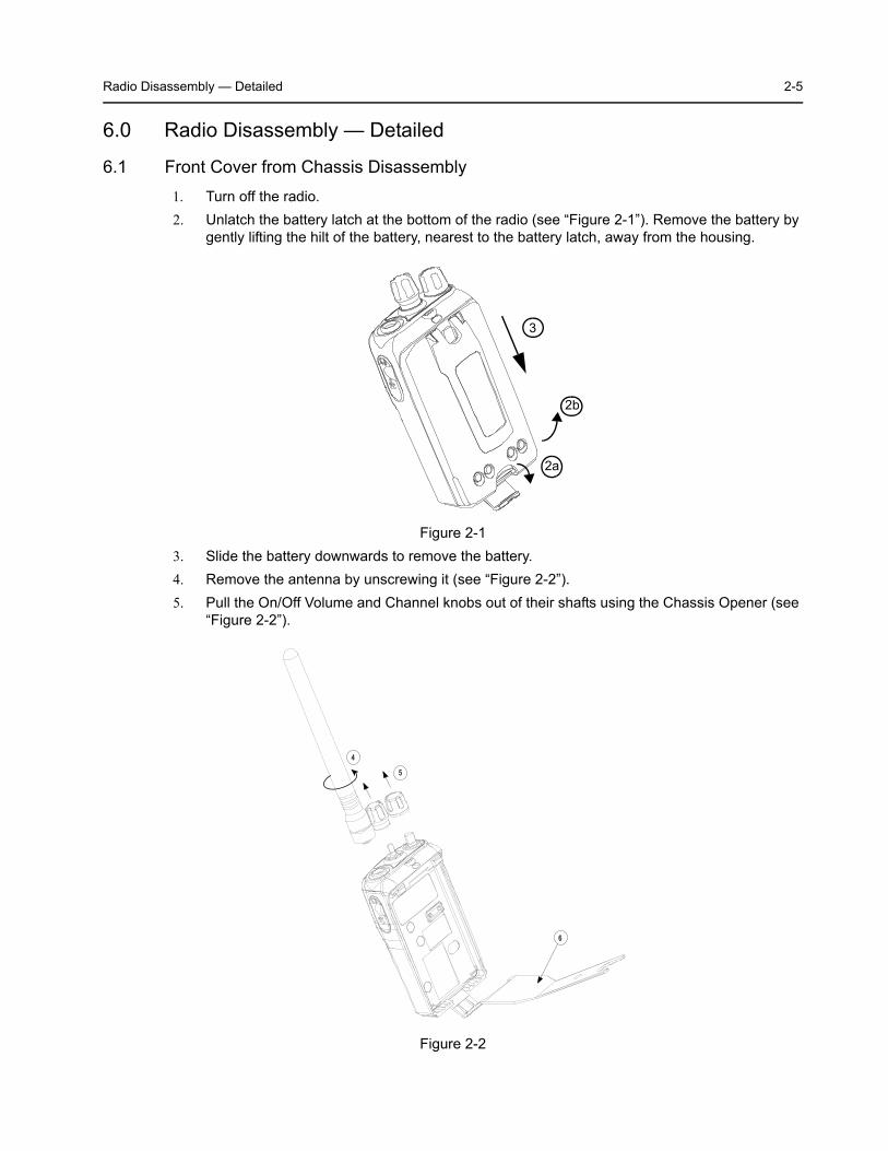
6.1 Front Cover from Chassis Disassembly1. Turn off the radio.2. Unlatch the battery latch at the bottom of the radio (see “Figure 2-1”). Remove the battery by
gently lifting the hilt of the battery, nearest to the battery latch, away from the housing.
3. Slide the battery downwards to remove the battery.4. Remove the antenna by unscrewing it (see “Figure 2-2”).5. Pull the On/Off Volume and Channel knobs out of their shafts using the Chassis Opener (see
“Figure 2-2”).
Figure 2-1
Figure 2-2
2a
2a3
2b
6
4
5
2-6 Radio Disassembly — Detailed
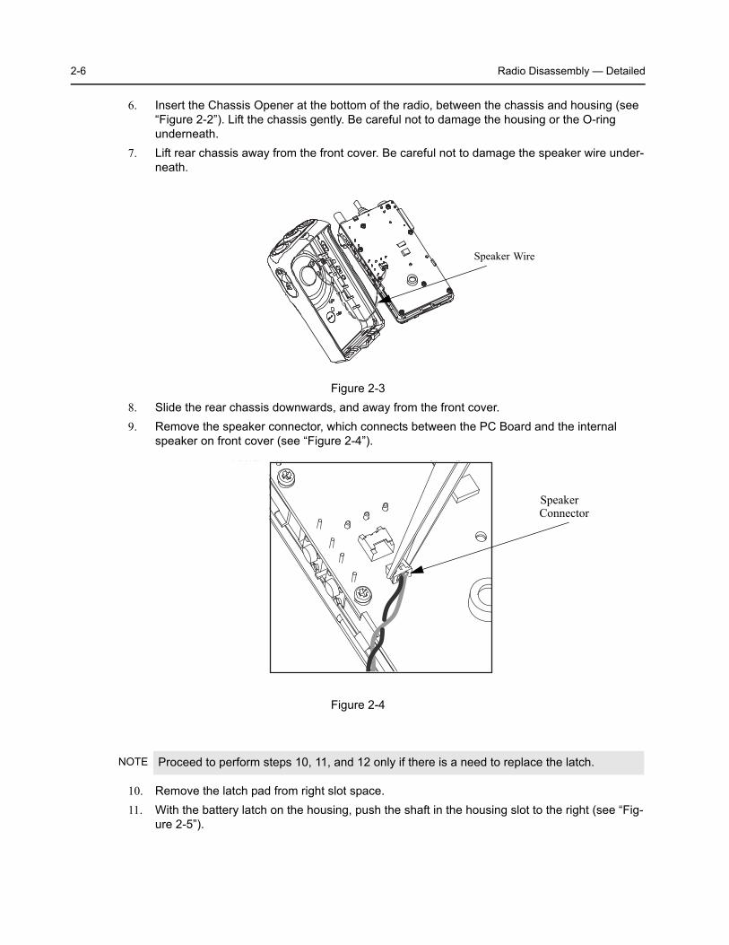
6. Insert the Chassis Opener at the bottom of the radio, between the chassis and housing (see “Figure 2-2”). Lift the chassis gently. Be careful not to damage the housing or the O-ring underneath.
7. Lift rear chassis away from the front cover. Be careful not to damage the speaker wire under-neath.
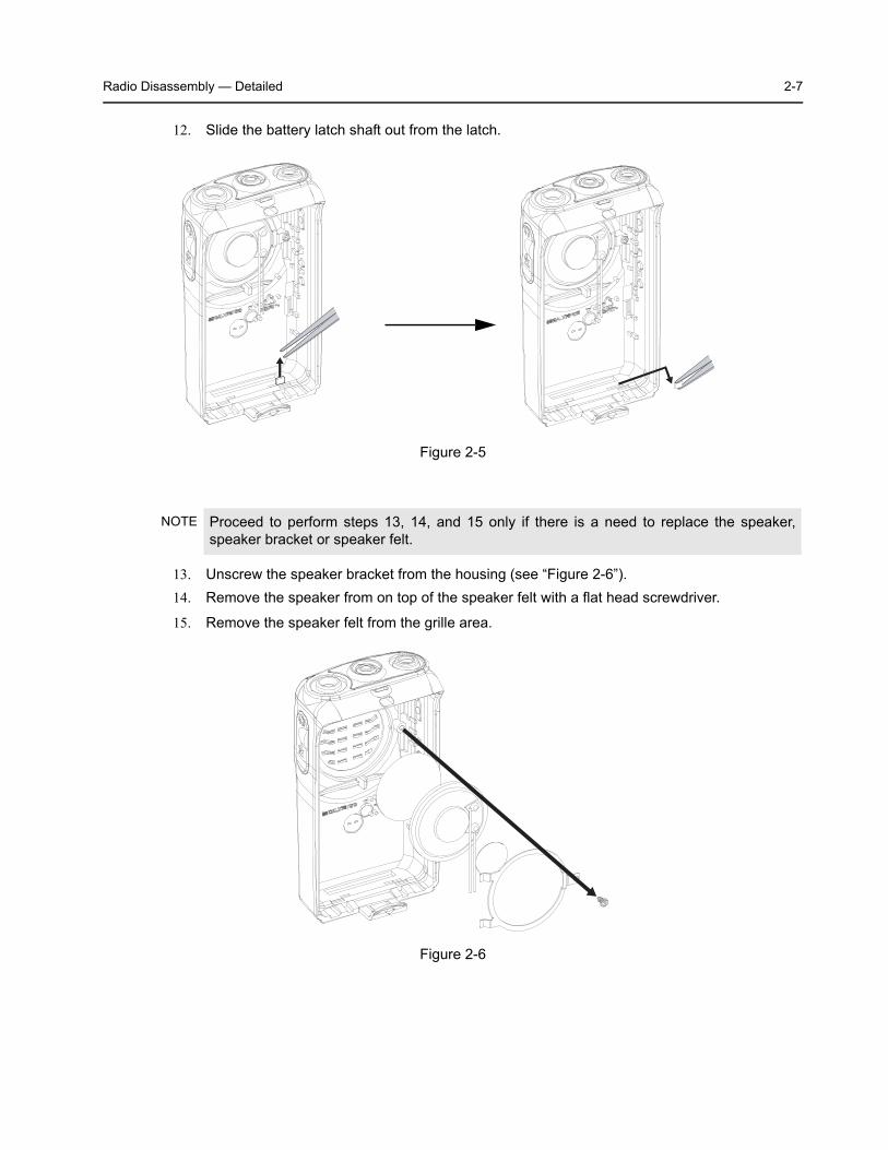
8. Slide the rear chassis downwards, and away from the front cover.9. Remove the speaker connector, which connects between the PC Board and the internal
speaker on front cover (see “Figure 2-4”).
10. Remove the latch pad from right slot space.11. With the battery latch on the housing, push the shaft in the housing slot to the right (see “Fig-
ure 2-5”).
Figure 2-3
Figure 2-4
NOTE Proceed to perform steps 10, 11, and 12 only if there is a need to replace the latch.
Speaker Wire
SpeakerConnector
Radio Disassembly — Detailed 2-7
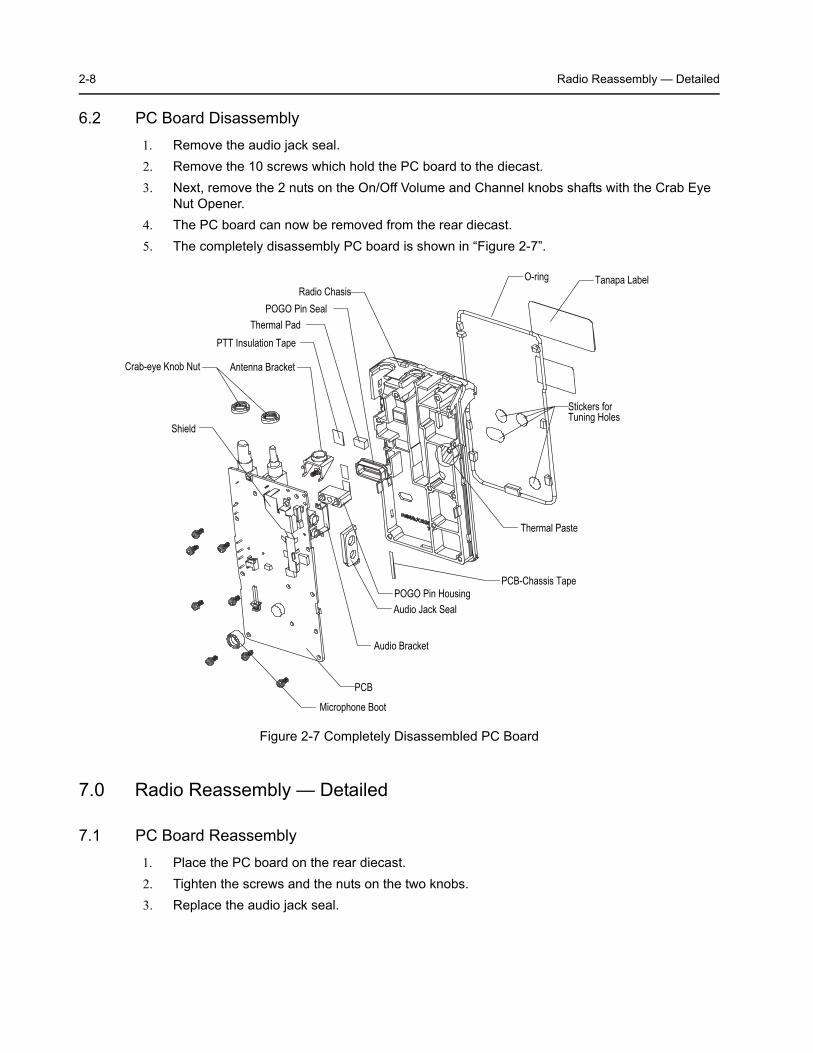
12. Slide the battery latch shaft out from the latch.
13. Unscrew the speaker bracket from the housing (see “Figure 2-6”).14. Remove the speaker from on top of the speaker felt with a flat head screwdriver.
15. Remove the speaker felt from the grille area.
Figure 2-5
NOTE Proceed to perform steps 13, 14, and 15 only if there is a need to replace the speaker, speaker bracket or speaker felt.
Figure 2-6
2-8 Radio Reassembly — Detailed
6.2 PC Board Disassembly1. Remove the audio jack seal.2. Remove the 10 screws which hold the PC board to the diecast.3. Next, remove the 2 nuts on the On/Off Volume and Channel knobs shafts with the Crab Eye
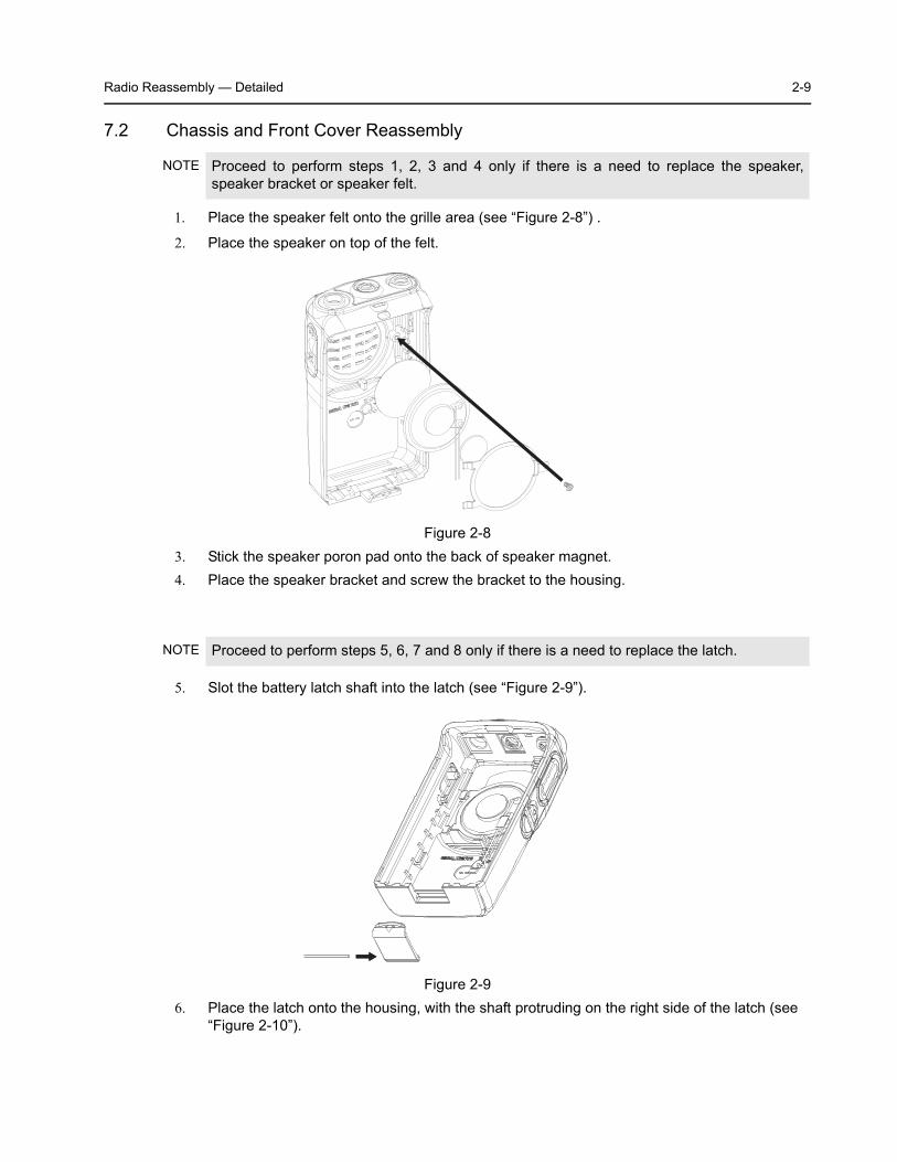
Nut Opener.4. The PC board can now be removed from the rear diecast.5. The completely disassembly PC board is shown in “Figure 2-7”.
7.0 Radio Reassembly — Detailed
7.1 PC Board Reassembly1. Place the PC board on the rear diecast.2. Tighten the screws and the nuts on the two knobs.3. Replace the audio jack seal.
Figure 2-7 Completely Disassembled PC Board
O-ringRadio Chasis
PCB
Antenna BracketCrab-eye Knob Nut
Audio Jack Seal
Microphone Boot
POGO Pin Housing
Audio Bracket
POGO Pin Seal
Tanapa Label
Stickers for Tuning Holes
Thermal Pad
Thermal Paste
PTT Insulation Tape
Shield
PCB-Chassis Tape
Radio Reassembly — Detailed 2-9
7.2 Chassis and Front Cover Reassembly
1. Place the speaker felt onto the grille area (see “Figure 2-8”) .
2. Place the speaker on top of the felt.
3. Stick the speaker poron pad onto the back of speaker magnet.4. Place the speaker bracket and screw the bracket to the housing.
5. Slot the battery latch shaft into the latch (see “Figure 2-9”).
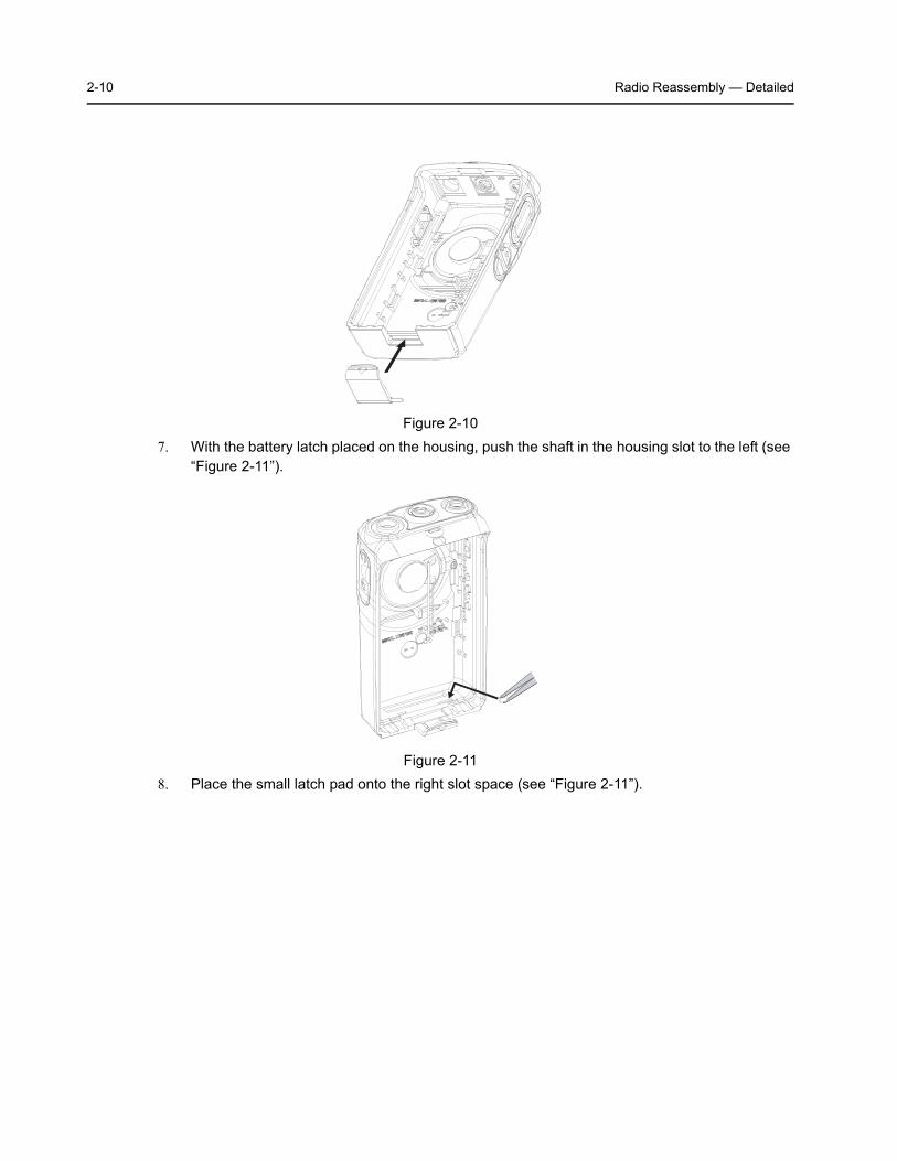
6. Place the latch onto the housing, with the shaft protruding on the right side of the latch (see “Figure 2-10”).
NOTE Proceed to perform steps 1, 2, 3 and 4 only if there is a need to replace the speaker, speaker bracket or speaker felt.
Figure 2-8
NOTE Proceed to perform steps 5, 6, 7 and 8 only if there is a need to replace the latch.
Figure 2-9
2-10 Radio Reassembly — Detailed
7. With the battery latch placed on the housing, push the shaft in the housing slot to the left (see “Figure 2-11”).
8. Place the small latch pad onto the right slot space (see “Figure 2-11”).
Figure 2-10
Figure 2-11
Radio Reassembly — Detailed 2-11
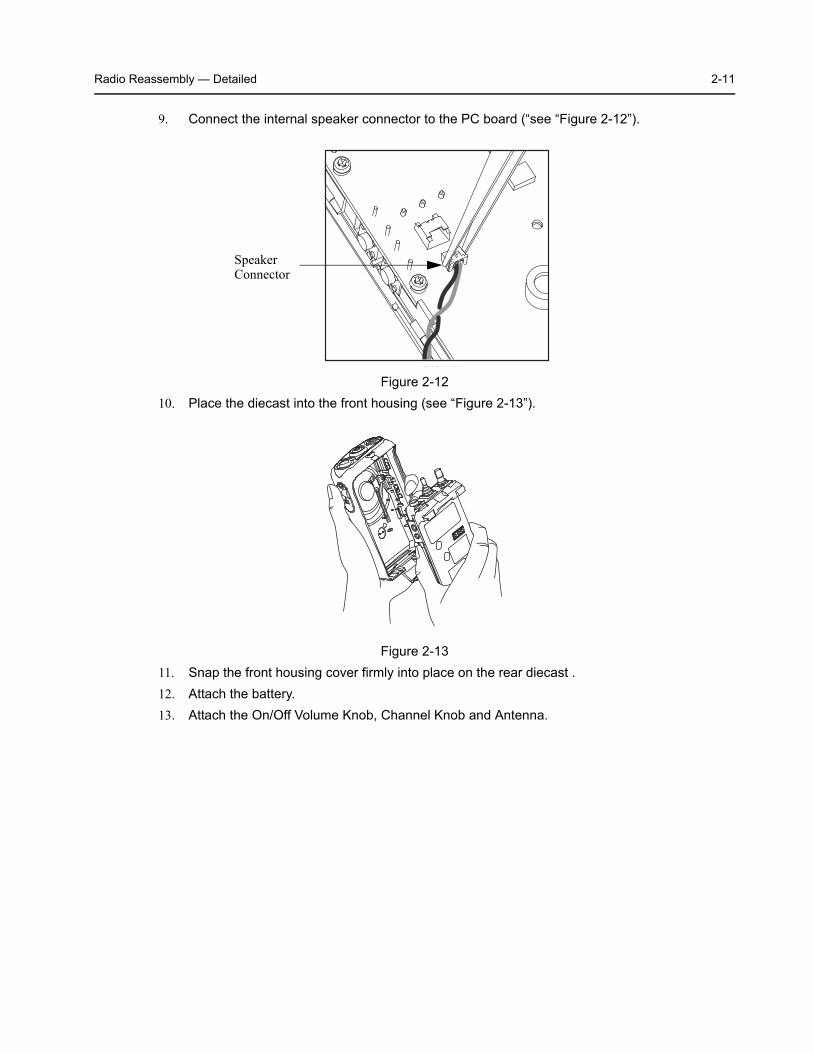
9. Connect the internal speaker connector to the PC board (“see “Figure 2-12”).
10. Place the diecast into the front housing (see “Figure 2-13”).
11. Snap the front housing cover firmly into place on the rear diecast .12. Attach the battery.13. Attach the On/Off Volume Knob, Channel Knob and Antenna.
Figure 2-12
Figure 2-13
SpeakerConnector
2-12 Mechanical View and Parts List
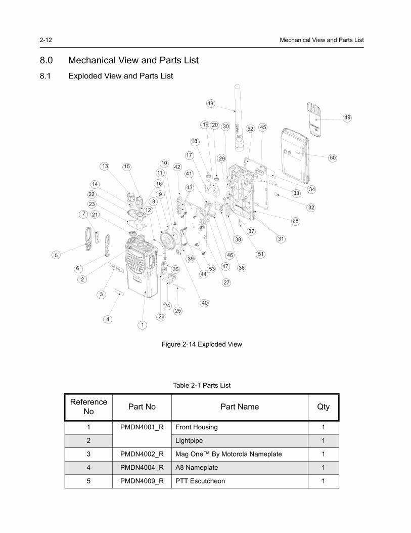
8.0 Mechanical View and Parts List8.1 Exploded View and Parts List
Figure 2-14 Exploded View
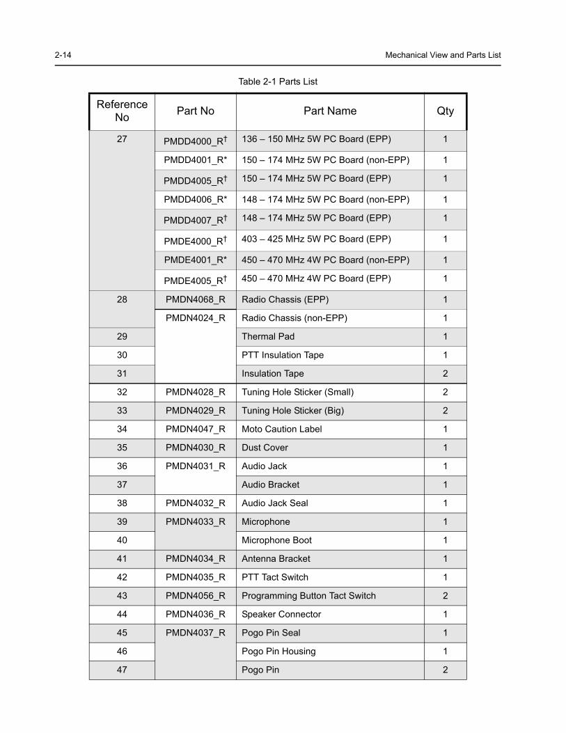
Table 2-1 Parts List
Reference No Part No Part Name Qty
1 PMDN4001_R Front Housing 1
2 Lightpipe 1
3 PMDN4002_R Mag One™ By Motorola Nameplate 1
4 PMDN4004_R A8 Nameplate 1
5 PMDN4009_R PTT Escutcheon 1
14
3
2
6
5
7 21
23
22
14
13 15
16
128
9
11
10
43
41
17
18
19 20 30
29
48
45
49
50
3433
32
28
3837
31
51
36
46
47
27
5344
39
40
35
2524
26
42
52
Mechanical View and Parts List 2-13
6 PMDN4007_R PTT Rubber 1
7 PMDN4010_R PTT Bezel 1
8 PMDN4011_R Speaker & Cable (non-EPP) 1
PMDN4067_R Speaker & Cable (EPP) 1
9 PMDN4012_R Speaker Bracket 1
10 Speaker Bracket Screw 1
11 PMDN4013_R Speaker Poron Pad 1
12 PMDN4046_R Speaker Felt 1
13 PMDN4014_R Volume Knob 1
14 Volume Knob D-Clip (D: 6.0) 1
15 PMDN4015_R Channel Knob 1
16 Channel Knob D-Clip (D: 3.5) 1
17 PMDN4016_R Volume Potentiometer 1
18 Crab-Eye Knob Nut 1
19 PMDN4017_R Channel Potentiometer 1
20 Crab-Eye Knob Nut 1
21 PMDN4018_R Channel & Volume Top Seal 1
22 PMDN4019_R Top Escutcheon 16 Channels 1
23 Top Adhesive 1
24 PMDN4023_R Battery Latch 1
25 Battery Latch Shaft 1
26 Battery Latch Tape 1
Table 2-1 Parts List
Reference No Part No Part Name Qty
2-14 Mechanical View and Parts List
27 PMDD4000_R† 136 – 150 MHz 5W PC Board (EPP) 1
PMDD4001_R* 150 – 174 MHz 5W PC Board (non-EPP) 1
PMDD4005_R† 150 – 174 MHz 5W PC Board (EPP) 1
PMDD4006_R* 148 – 174 MHz 5W PC Board (non-EPP) 1
PMDD4007_R† 148 – 174 MHz 5W PC Board (EPP) 1
PMDE4000_R† 403 – 425 MHz 5W PC Board (EPP) 1
PMDE4001_R* 450 – 470 MHz 4W PC Board (non-EPP) 1
PMDE4005_R† 450 – 470 MHz 4W PC Board (EPP) 1
28 PMDN4068_R Radio Chassis (EPP) 1
PMDN4024_R Radio Chassis (non-EPP) 1
29 Thermal Pad 1
30 PTT Insulation Tape 1
31 Insulation Tape 2
32 PMDN4028_R Tuning Hole Sticker (Small) 2
33 PMDN4029_R Tuning Hole Sticker (Big) 2
34 PMDN4047_R Moto Caution Label 1
35 PMDN4030_R Dust Cover 1
36 PMDN4031_R Audio Jack 1
37 Audio Bracket 1
38 PMDN4032_R Audio Jack Seal 1
39 PMDN4033_R Microphone 1
40 Microphone Boot 1
41 PMDN4034_R Antenna Bracket 1
42 PMDN4035_R PTT Tact Switch 1
43 PMDN4056_R Programming Button Tact Switch 2
44 PMDN4036_R Speaker Connector 1
45 PMDN4037_R Pogo Pin Seal 1
46 Pogo Pin Housing 1
47 Pogo Pin 2
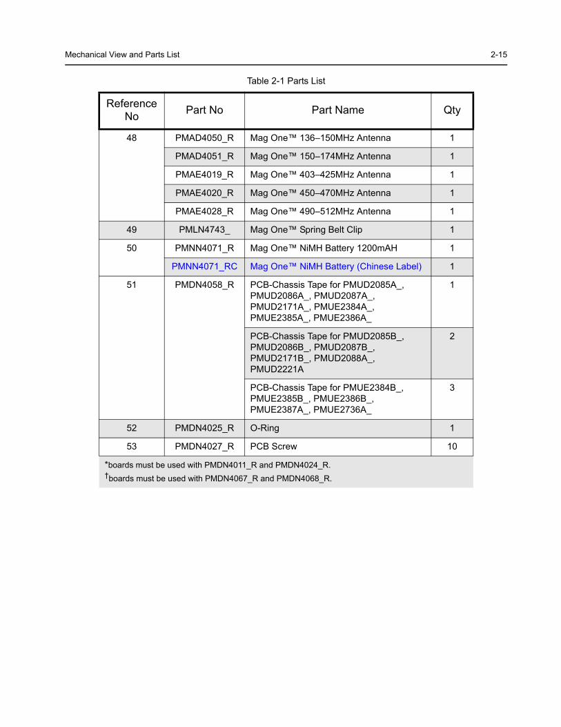
Table 2-1 Parts List
Reference No Part No Part Name Qty
Mechanical View and Parts List 2-15
48 PMAD4050_R Mag One™ 136–150MHz Antenna 1
PMAD4051_R Mag One™ 150–174MHz Antenna 1
PMAE4019_R Mag One™ 403–425MHz Antenna 1
PMAE4020_R Mag One™ 450–470MHz Antenna 1
PMAE4028_R Mag One™ 490–512MHz Antenna 1
49 PMLN4743_ Mag One™ Spring Belt Clip 1
50 PMNN4071_R Mag One™ NiMH Battery 1200mAH 1
PMNN4071_RC Mag One™ NiMH Battery (Chinese Label) 1
51 PMDN4058_R PCB-Chassis Tape for PMUD2085A_, PMUD2086A_, PMUD2087A_, PMUD2171A_, PMUE2384A_, PMUE2385A_, PMUE2386A_
1
PCB-Chassis Tape for PMUD2085B_, PMUD2086B_, PMUD2087B_, PMUD2171B_, PMUD2088A_, PMUD2221A
2
PCB-Chassis Tape for PMUE2384B_, PMUE2385B_, PMUE2386B_, PMUE2387A_, PMUE2736A_
3
52 PMDN4025_R O-Ring 1
53 PMDN4027_R PCB Screw 10
*boards must be used with PMDN4011_R and PMDN4024_R.†boards must be used with PMDN4067_R and PMDN4068_R.
Table 2-1 Parts List
Reference No Part No Part Name Qty
2-16 Service Aids
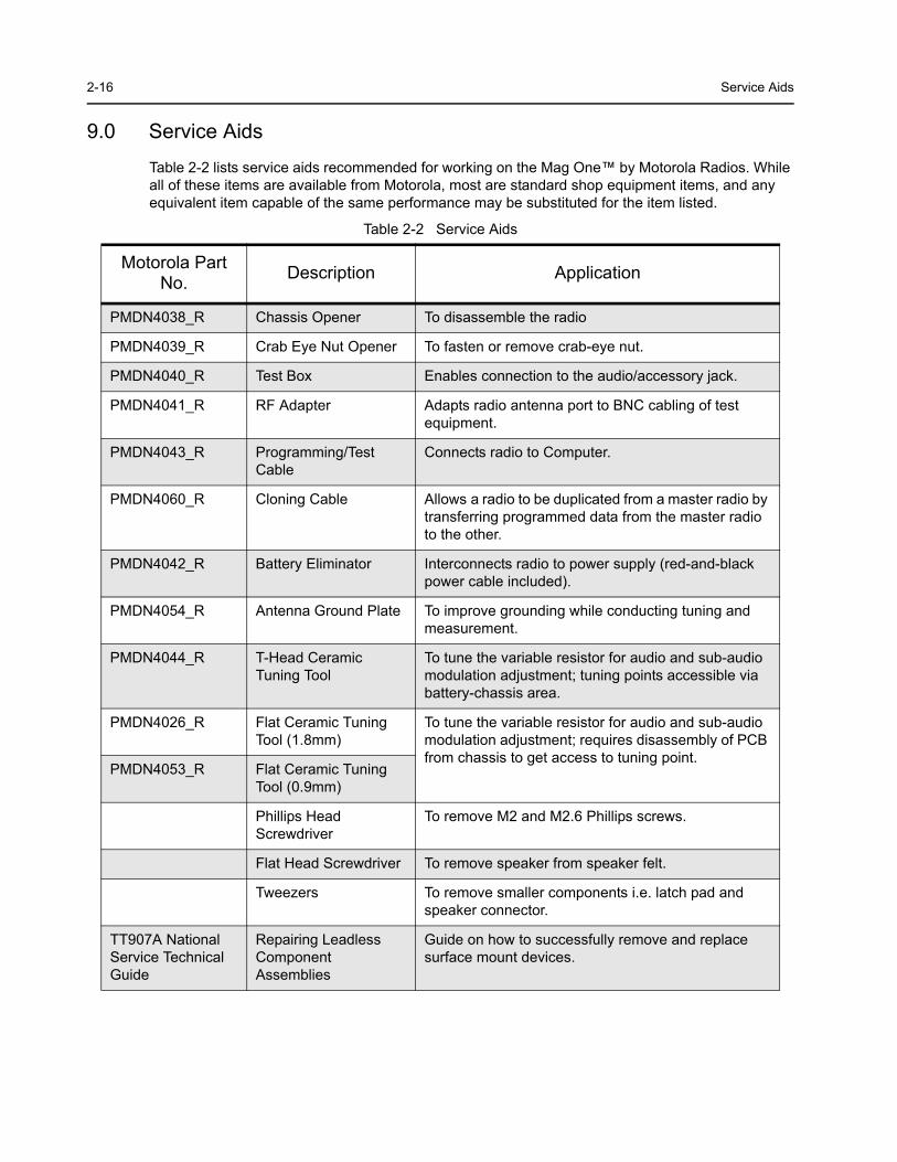
9.0 Service Aids
Table 2-2 lists service aids recommended for working on the Mag One™ by Motorola Radios. While all of these items are available from Motorola, most are standard shop equipment items, and any equivalent item capable of the same performance may be substituted for the item listed.
Table 2-2 Service Aids
Motorola Part No. Description Application
PMDN4038_R Chassis Opener To disassemble the radio
PMDN4039_R Crab Eye Nut Opener To fasten or remove crab-eye nut.
PMDN4040_R Test Box Enables connection to the audio/accessory jack.
PMDN4041_R RF Adapter Adapts radio antenna port to BNC cabling of test equipment.
PMDN4043_R Programming/Test Cable
Connects radio to Computer.
PMDN4060_R Cloning Cable Allows a radio to be duplicated from a master radio by transferring programmed data from the master radio to the other.
PMDN4042_R Battery Eliminator Interconnects radio to power supply (red-and-black power cable included).
PMDN4054_R Antenna Ground Plate To improve grounding while conducting tuning and measurement.
PMDN4044_R T-Head Ceramic Tuning Tool
To tune the variable resistor for audio and sub-audio modulation adjustment; tuning points accessible via battery-chassis area.
PMDN4026_R Flat Ceramic Tuning Tool (1.8mm)
To tune the variable resistor for audio and sub-audio modulation adjustment; requires disassembly of PCB from chassis to get access to tuning point.
PMDN4053_R Flat Ceramic Tuning Tool (0.9mm)
Phillips Head Screwdriver
To remove M2 and M2.6 Phillips screws.
Flat Head Screwdriver To remove speaker from speaker felt.
Tweezers To remove smaller components i.e. latch pad and speaker connector.
TT907A National Service Technical Guide
Repairing Leadless Component Assemblies
Guide on how to successfully remove and replace surface mount devices.
Test Equipment 2-17
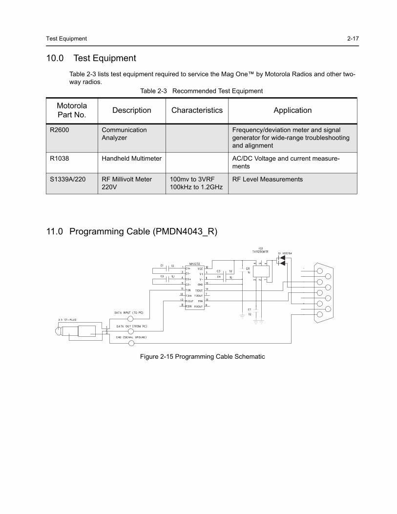
10.0 Test Equipment
Table 2-3 lists test equipment required to service the Mag One™ by Motorola Radios and other two-way radios.
11.0 Programming Cable (PMDN4043_R)
Table 2-3 Recommended Test Equipment
Motorola Part No. Description Characteristics Application
R2600 Communication Analyzer
Frequency/deviation meter and signal generator for wide-range troubleshooting and alignment
R1038 Handheld Multimeter AC/DC Voltage and current measure-ments
S1339A/220 RF Millivolt Meter 220V
100mv to 3VRF 100kHz to 1.2GHz
RF Level Measurements
Figure 2-15 Programming Cable Schematic
2-18
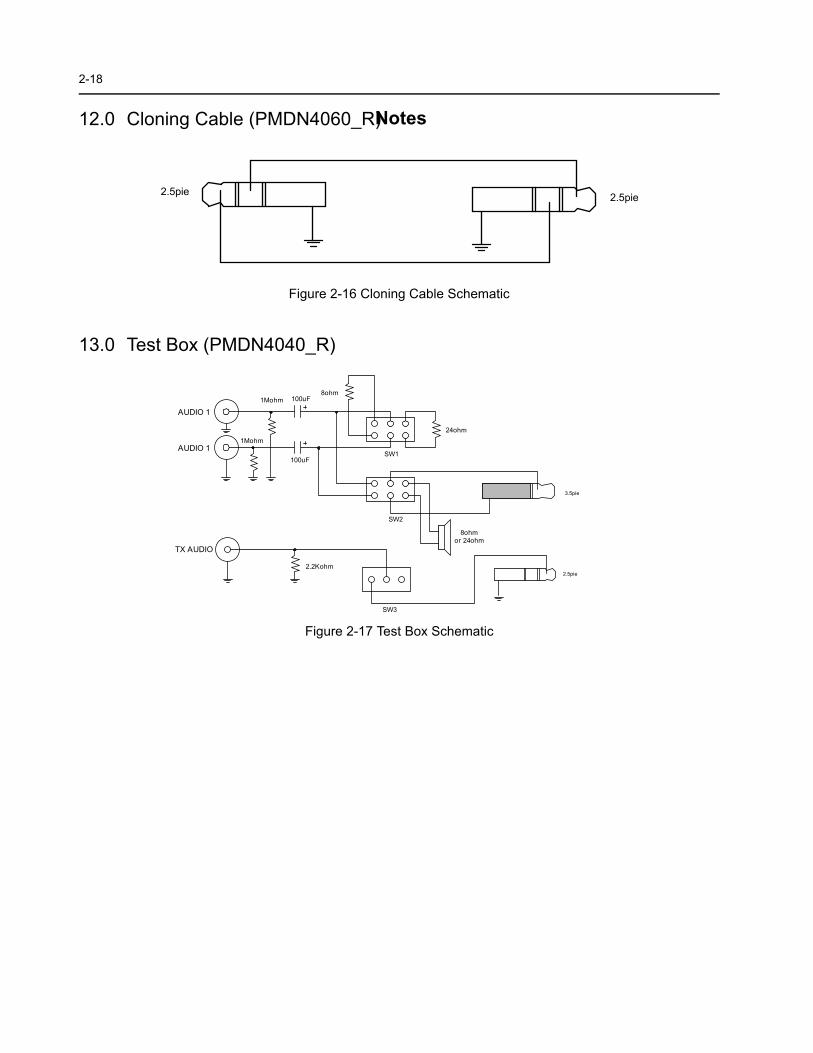
Notes12.0 Cloning Cable (PMDN4060_R)
13.0 Test Box (PMDN4040_R)
Figure 2-16 Cloning Cable Schematic
Figure 2-17 Test Box Schematic
eip5.2eip5.2
5.2 eip
5.3 eip
1 OIDUA
1 OIDUA
OIDUA XT
oM1 mh
oM1 mh 001 Fu
001 Fu
o8 mh
42 mho
o8 mh2 ro mho4
S 1W
S 2W
S 3W
K2.2 mho
3-1
Section 3
RADIO TUNING
1.0 Introduction
This chapter provides an overview of the hardware tuning for this Mag One™ Series radio. There is no software tuning required.
In order to perform the manual tuning procedures, the radio needs to be disassembled to the PC Board.
Following are the parameters that can be tuned:-
1. Transmitter Tuninga. High Power Tuning
b. Low Power Tuning
c. Frequency Tuning
d. Modulation Balancing
e. Maximum Modulation
f. Subtone Modulation
2. Receiver Tuning a. Wide Band Sinad Tuning
b. Narrow Band Sinad Tuning
3. PLL Synthesizer Tuninga. Rx PLL Frequency Tuning
b. Tx PLL Frequency Tuning
For a list of Service Aids required, refer to Table 2-2 on page 2-16Parts ListParts List
3-2 Hardware Tuning Setup and Procedure
2.0 Hardware Tuning Setup and Procedure
2.1 Tuning Frequency
2.2 Preparation Before Tuning (refer to Figure 3-1)1. Set Power Supply to 7.5V and then connect to the radio.2. Connect the connector and ground plate to the radio antenna port.
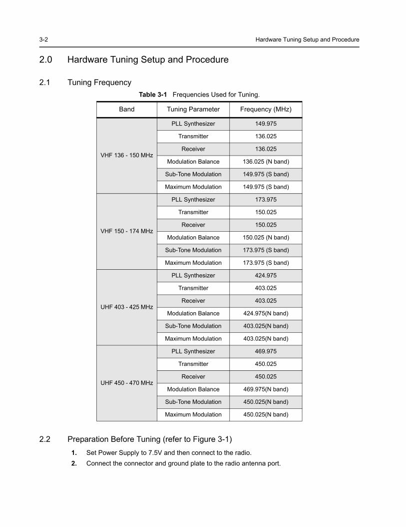
Table 3-1 Frequencies Used for Tuning.
Band Tuning Parameter Frequency (MHz)
VHF 136 - 150 MHz
PLL Synthesizer 149.975
Transmitter 136.025
Receiver 136.025
Modulation Balance 136.025 (N band)
Sub-Tone Modulation 149.975 (S band)
Maximum Modulation 149.975 (S band)
VHF 150 - 174 MHz
PLL Synthesizer 173.975
Transmitter 150.025
Receiver 150.025
Modulation Balance 150.025 (N band)
Sub-Tone Modulation 173.975 (S band)
Maximum Modulation 173.975 (S band)
UHF 403 - 425 MHz
PLL Synthesizer 424.975
Transmitter 403.025
Receiver 403.025
Modulation Balance 424.975(N band)
Sub-Tone Modulation 403.025(N band)
Maximum Modulation 403.025(N band)
UHF 450 - 470 MHz
PLL Synthesizer 469.975
Transmitter 450.025
Receiver 450.025
Modulation Balance 469.975(N band)
Sub-Tone Modulation 450.025(N band)
Maximum Modulation 450.025(N band)
Hardware Tuning Setup and Procedure 3-3
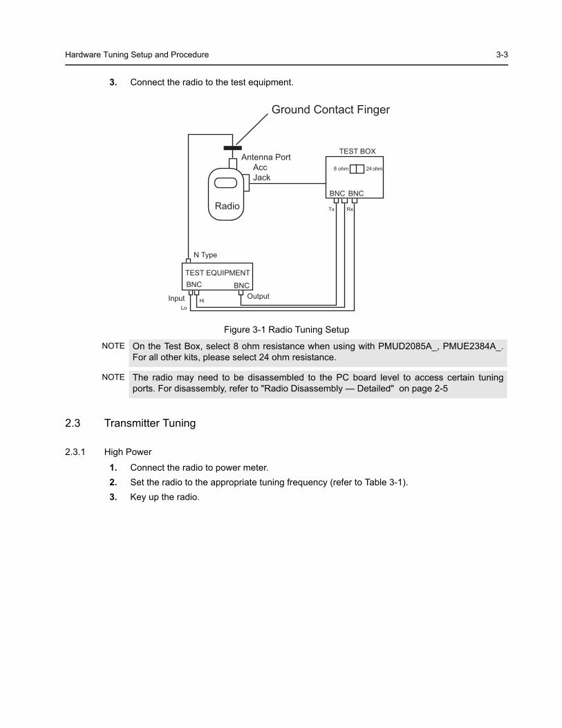
3. Connect the radio to the test equipment.
2.3 Transmitter Tuning
2.3.1 High Power
1. Connect the radio to power meter. 2. Set the radio to the appropriate tuning frequency (refer to Table 3-1).3. Key up the radio.
Figure 3-1 Radio Tuning Setup
NOTE On the Test Box, select 8 ohm resistance when using with PMUD2085A_, PMUE2384A_. For all other kits, please select 24 ohm resistance.
NOTE The radio may need to be disassembled to the PC board level to access certain tuning ports. For disassembly, refer to "Radio Disassembly — Detailed" on page 2-5
Ground Contact Finger
Radio
Antenna Port Acc Jack
TEST EQUIPMENT
N Type
BNC
InputLo
Hi
Tx
8 ohm 24 ohm
Rx
TEST BOX
OutputBNC
BNC BNC
3-4 Hardware Tuning Setup and Procedure
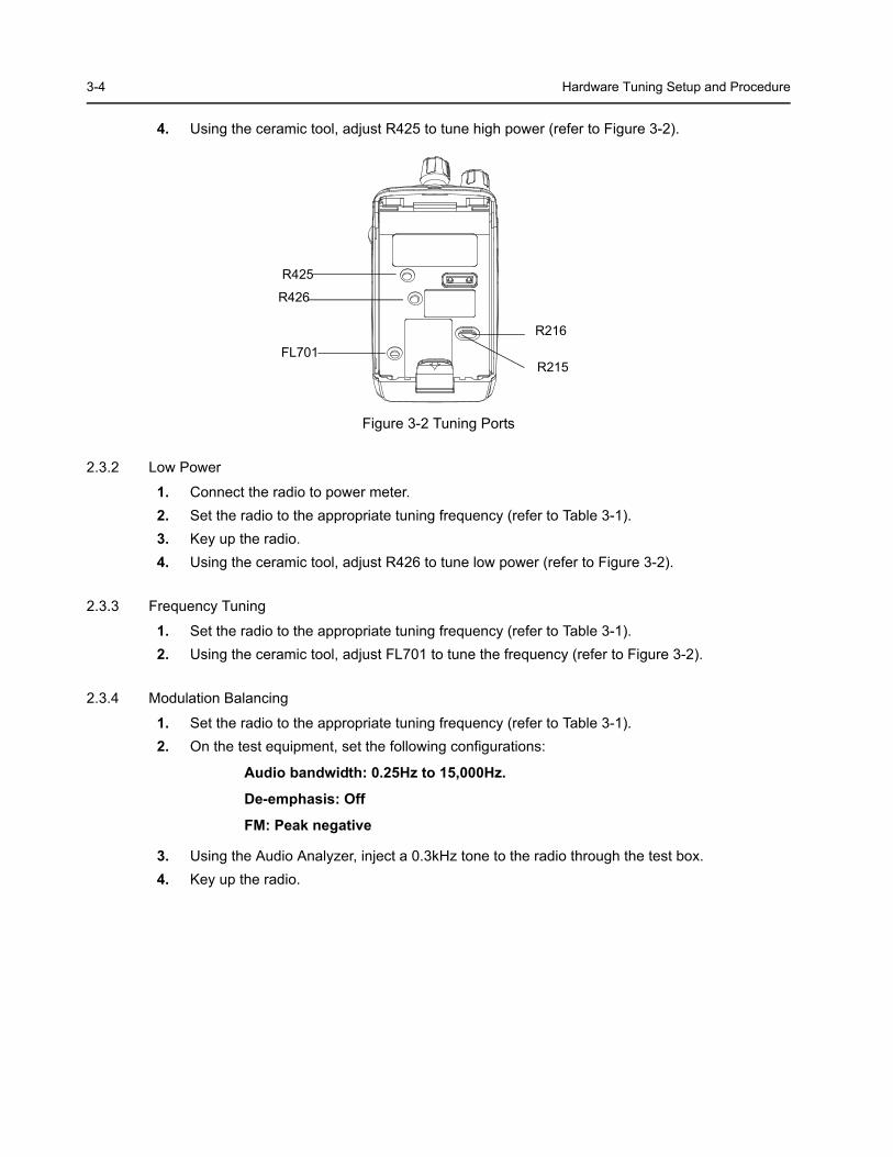
4. Using the ceramic tool, adjust R425 to tune high power (refer to Figure 3-2).
2.3.2 Low Power
1. Connect the radio to power meter. 2. Set the radio to the appropriate tuning frequency (refer to Table 3-1).3. Key up the radio.4. Using the ceramic tool, adjust R426 to tune low power (refer to Figure 3-2).
2.3.3 Frequency Tuning
1. Set the radio to the appropriate tuning frequency (refer to Table 3-1). 2. Using the ceramic tool, adjust FL701 to tune the frequency (refer to Figure 3-2).
2.3.4 Modulation Balancing
1. Set the radio to the appropriate tuning frequency (refer to Table 3-1). 2. On the test equipment, set the following configurations:
Audio bandwidth: 0.25Hz to 15,000Hz.
De-emphasis: Off
FM: Peak negative
3. Using the Audio Analyzer, inject a 0.3kHz tone to the radio through the test box.4. Key up the radio.
Figure 3-2 Tuning Ports
R425
R426
FL701R216
R215
Hardware Tuning Setup and Procedure 3-5
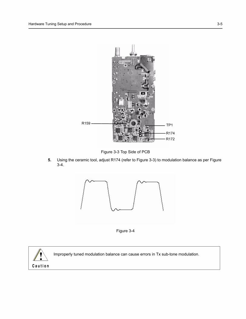
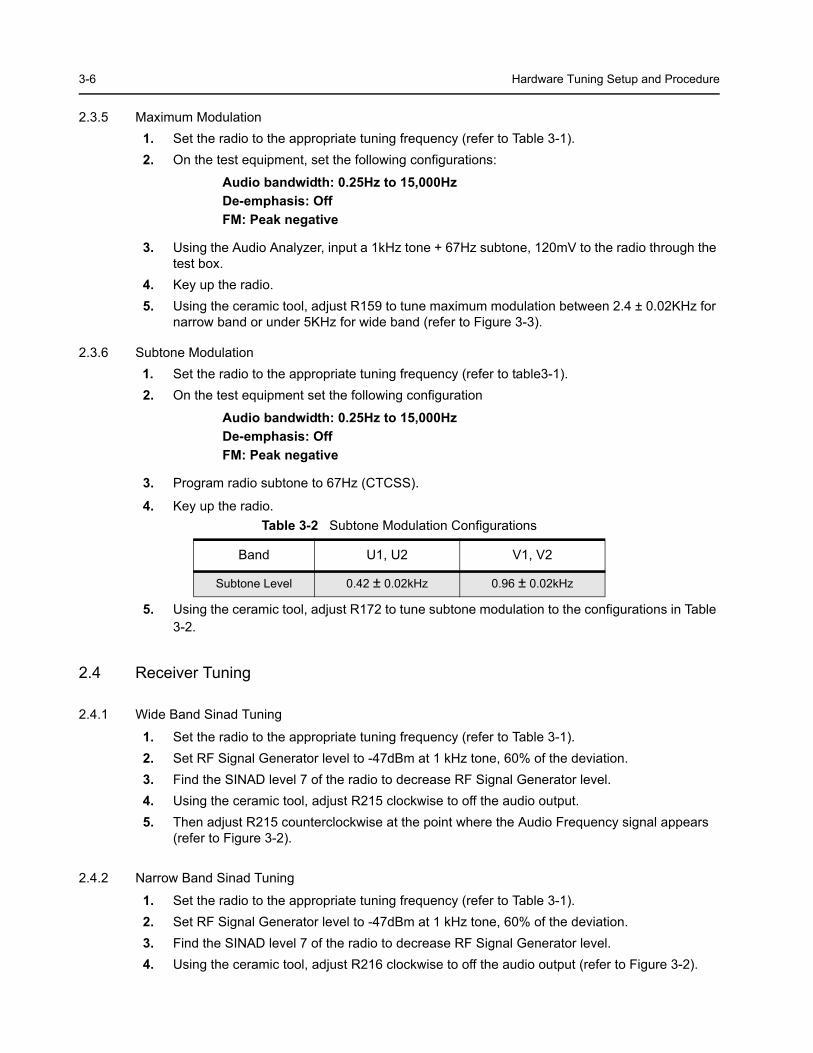
5. Using the ceramic tool, adjust R174 (refer to Figure 3-3) to modulation balance as per Figure 3-4.
Figure 3-3 Top Side of PCB
Figure 3-4
Improperly tuned modulation balance can cause errors in Tx sub-tone modulation.
R159 TP1
R174R172
3-6 Hardware Tuning Setup and Procedure
2.3.5 Maximum Modulation1. Set the radio to the appropriate tuning frequency (refer to Table 3-1).2. On the test equipment, set the following configurations:
Audio bandwidth: 0.25Hz to 15,000Hz De-emphasis: OffFM: Peak negative
3. Using the Audio Analyzer, input a 1kHz tone + 67Hz subtone, 120mV to the radio through the test box.
4. Key up the radio. 5. Using the ceramic tool, adjust R159 to tune maximum modulation between 2.4 ± 0.02KHz for
narrow band or under 5KHz for wide band (refer to Figure 3-3).
2.3.6 Subtone Modulation1. Set the radio to the appropriate tuning frequency (refer to table3-1).2. On the test equipment set the following configuration
Audio bandwidth: 0.25Hz to 15,000HzDe-emphasis: OffFM: Peak negative
3. Program radio subtone to 67Hz (CTCSS).
4. Key up the radio.
5. Using the ceramic tool, adjust R172 to tune subtone modulation to the configurations in Table 3-2.
2.4 Receiver Tuning
2.4.1 Wide Band Sinad Tuning
1. Set the radio to the appropriate tuning frequency (refer to Table 3-1).2. Set RF Signal Generator level to -47dBm at 1 kHz tone, 60% of the deviation.3. Find the SINAD level 7 of the radio to decrease RF Signal Generator level.4. Using the ceramic tool, adjust R215 clockwise to off the audio output.5. Then adjust R215 counterclockwise at the point where the Audio Frequency signal appears
(refer to Figure 3-2).
2.4.2 Narrow Band Sinad Tuning
1. Set the radio to the appropriate tuning frequency (refer to Table 3-1).2. Set RF Signal Generator level to -47dBm at 1 kHz tone, 60% of the deviation.3. Find the SINAD level 7 of the radio to decrease RF Signal Generator level.4. Using the ceramic tool, adjust R216 clockwise to off the audio output (refer to Figure 3-2).
Table 3-2 Subtone Modulation Configurations
Band U1, U2 V1, V2
Subtone Level 0.42 ± 0.02kHz 0.96 ± 0.02kHz
Hardware Tuning Setup and Procedure 3-7
5. Then adjust R216 counterclockwise at the point where the Audio Frequency signal appears.
2.4.3 PLL Synthesizer Tuning
Rx PLL Frequency Tuning
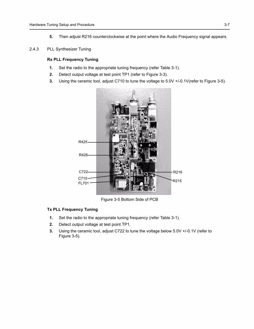
1. Set the radio to the appropriate tuning frequency (refer Table 3-1). 2. Detect output voltage at test point TP1 (refer to Figure 3-3).3. Using the ceramic tool, adjust C710 to tune the voltage to 5.0V +/-0.1V(refer to Figure 3-5).
Tx PLL Frequency Tuning
1. Set the radio to the appropriate tuning frequency (refer Table 3-1). 2. Detect output voltage at test point TP1.3. Using the ceramic tool, adjust C722 to tune the voltage below 5.0V +/-0.1V (refer to
Figure 3-5).
Figure 3-5 Bottom Side of PCB
R425
R216
R215
R426
C722
C710FL701

3-8
Notes
Introduction 4-1
Section 4
RADIO PROGRAMMING
1.0 Introduction
The radios can be programmed using the Customer Programming Software (CPS).
2.0 Programming Your Radio
2.1 Overview of the Programming Process
To prepare properly programmed radios for your customers, you should
1. program your radio with all the necessary parameters, as required by your customers, and then
2. clone these parameters over to all your customer’s radios.
2.2 Cloning Radio Parameters to User Radios
Cloning duplicates the contents of Radio 1 (master radio) into Radio 2 (slave radio).
2.3 Parameters which are cloned• Radio Configuration parameters• Conventional Personality parameters
2.4 Parameters which are not cloned• Unit Serial Number.• Model Number
2.5 To Clone a Radio
Cloning duplicates the contents of your radio (master radio) into your customer’s radio (slave radio). Tuning and alignment information are not affected by cloning.
2.5.1 Setting Up the Master Radio
1. Turn off the radio.2. Press and hold Programmable Button 1 (the top programmable button) and turn on the radio.
Keep pressing the Programmable Button 1 until beep is heard twice. 3. Release Programmable Button 1. Notice that the LED changes to RED.
4-2 CPS Programming
2.5.2 Setting Up the Slave Radio
1. Turn off the radio.2. Press and hold Programmable Button 1(the top programmable button) and turn on the radio.
Keep pressing Programmable Button 1 until the beep is heard three times. 3. Release Programmable Button 1. Notice that the LED changes to GREEN.
2.5.3 Radio to Radio Cloning Procedures
1. Connect the cloning cable to both the Master and Slave radio.2. Press and release Programmable Button 1 of the Slave radio.3. Press and release Programmable Button 1 of the Master radio.4. The LED for both radios show flashing orange during cloning. 5. Once cloning is completed, an ‘Out Chirp’ alert tone can be heard from both radios.6. Disconnect radios from the cloning cable. They are now ready for operation.
2.6 Error Conditions
An error may occur when cloning a radio. When this happens, the radio sounds a Faulty Condition Alert tone and shows a Flashing Orange LED momentarily.
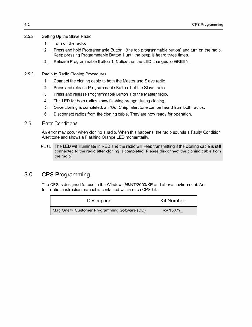
3.0 CPS Programming
The CPS is designed for use in the Windows 98/NT/2000/XP and above environment. An Installation instruction manual is contained within each CPS kit.
NOTE The LED will illuminate in RED and the radio will keep transmitting if the cloning cable is still connected to the radio after cloning is completed. Please disconnect the cloning cable from the radio
Description Kit Number
Mag One™ Customer Programming Software (CD) RVN5079_
Factory Reset 4-3
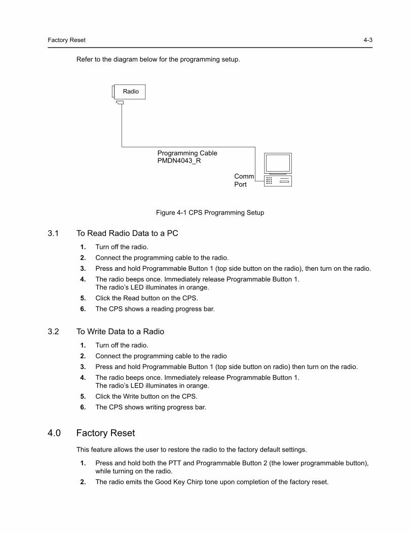
Refer to the diagram below for the programming setup.
3.1 To Read Radio Data to a PC 1. Turn off the radio.2. Connect the programming cable to the radio.3. Press and hold Programmable Button 1 (top side button on the radio), then turn on the radio.4. The radio beeps once. Immediately release Programmable Button 1.
The radio’s LED illuminates in orange.5. Click the Read button on the CPS.6. The CPS shows a reading progress bar.
3.2 To Write Data to a Radio 1. Turn off the radio.2. Connect the programming cable to the radio3. Press and hold Programmable Button 1 (top side button on radio) then turn on the radio.4. The radio beeps once. Immediately release Programmable Button 1.
The radio’s LED illuminates in orange.5. Click the Write button on the CPS.6. The CPS shows writing progress bar.
4.0 Factory Reset
This feature allows the user to restore the radio to the factory default settings.
1. Press and hold both the PTT and Programmable Button 2 (the lower programmable button), while turning on the radio.
2. The radio emits the Good Key Chirp tone upon completion of the factory reset.
Figure 4-1 CPS Programming Setup
Radio
Programming Cable
Comm Port
PMDN4043_R

4-4 Factory Reset
Notes
Antennas 5-1
Section 5
ACCESSORIES
1.0 Antennas
PMAD4050_R Mag One™ 136–150MHz Antenna
PMAD4051_R Mag One™150–174MHz Antenna
PMAE4019_R Mag One™ 403–425MHz Antenna
PMAE4020_R Mag One™ 450–470MHz Antenna
PMAE4028_R Mag One™ 490–512MHz Antenna
2.0 Carry Accessories
PMLN4691_R Mag One™ Belt Clip
PMLN4743_ Mag One™ Spring Belt Clip
3.0 Carry Cases
PMLN4741_ Soft Leather Carry Case
PMLN4742_ Hard Leather Carry Case
4.0 Chargers
AZPMLN4685_R Mag One™ Mid-rate Charger Base
AZPMLN4686_R Mag One™ Mid-rate Charger 110V 60Hz US 2-pin
AZPMLN4687_R Mag One™ Mid-rate Charger 240V 50Hz UK 3-pin
AZPMLN4688_R Mag One™ Mid-rate Charger 230V 50Hz EU 2-pin
PMLN4689_R Mag One™ Mid-rate Charger 220V 50Hz CN 2-pin
PMLN4826_R Mag One™ Mid-rate Transformer 110V US 2-pin
PMLN4827_R Mag One™ Mid-rate Transformer 240V UK 3-pin
PMLN4828_R Mag One™ Mid-rate Transformer 230V EU 2-pin
PMLN4830_R Mag One™ Mid-rate Transformer 220V CN 2-pin
5.0 Batteries
PMNN4071_R Mag One™ NiMH Battery, 1200mAH
PMNN4071_RC Mag One™ NiMH Battery 1200mAH (Chinese Label)
5-2 Audio Accessories
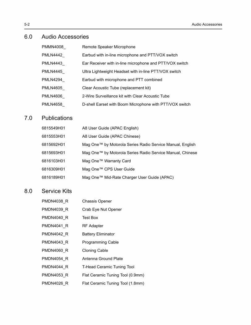
6.0 Audio Accessories
PMMN4008_ Remote Speaker Microphone
PMLN4442_ Earbud with in-line microphone and PTT/VOX switch
PMLN4443_ Ear Receiver with in-line microphone and PTT/VOX switch
PMLN4445_ Ultra Lightweight Headset with in-line PTT/VOX switch
PMLN4294_ Earbud with microphone and PTT combined
PMLN4605_ Clear Acoustic Tube (replacement kit)
PMLN4606_ 2-Wire Surveillance kit with Clear Acoustic Tube
PMLN4658_ D-shell Earset with Boom Microphone with PTT/VOX switch
7.0 Publications
6815549H01 A8 User Guide (APAC English)
6815553H01 A8 User Guide (APAC Chinese)
6815692H01 Mag One™ by Motorola Series Radio Service Manual, English
6815693H01 Mag One™ by Motorola Series Radio Service Manual, Chinese
6816103H01 Mag One™ Warranty Card
6816309H01 Mag One™ CPS User Guide
6816189H01 Mag One™ Mid-Rate Charger User Guide (APAC)
8.0 Service Kits
PMDN4038_R Chassis Opener
PMDN4039_R Crab Eye Nut Opener
PMDN4040_R Test Box
PMDN4041_R RF Adapter
PMDN4042_R Battery Eliminator
PMDN4043_R Programming Cable
PMDN4060_R Cloning Cable
PMDN4054_R Antenna Ground Plate
PMDN4044_R T-Head Ceramic Tuning Tool
PMDN4053_R Flat Ceramic Tuning Tool (0.9mm)
PMDN4026_R Flat Ceramic Tuning Tool (1.8mm)
VHF Band 1 Information (136–150 MHz) 6-1
Section 6
MODEL CHART AND TEST SPECIFICATION
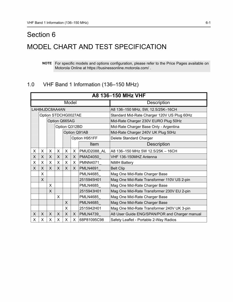
1.0 VHF Band 1 Information (136–150 MHz)
NOTE For specific models and options configuration, please refer to the Price Pages available on Motorola Online at https://businessonline.motorola.com/ .
A8 136–150 MHz VHF Model Description
LAH84JDC8AA4AN A8 136–150 MHz, 5W, 12.5/25K–16CHOption STDCHG0027AE Standard Mid-Rate Charger 120V US Plug 60Hz
Option Q665AG Mid-Rate Charger 230V EURO Plug 50HzOption Q312BD Mid-Rate Charger Base Only - Argentina
Option Q91AB Mid-Rate Charger 240V UK Plug 50HzOption H951FF Delete Standard Charger
Item DescriptionX X X X X X PMUD2088_AL A8 136–150 MHz 5W 12.5/25K – 16CHX X X X X X PMAD4050_ VHF 136-150MHZ AntennaX X X X X X PMNN4071_ NiMH BatteryX X X X X X PMLN4691_ Belt Clip
X PMLN4685_ Mag One Mid-Rate Charger BaseX 2515945H01 Mag One Mid-Rate Transformer 110V US 2-pin
X PMLN4685_ Mag One Mid-Rate Charger BaseX 2515943H01 Mag One Mid-Rate Transformer 230V EU 2-pin
X PMLN4685_ Mag One Mid-Rate Charger BaseX PMLN4685_ Mag One Mid-Rate Charger BaseX 2515942H01 Mag One Mid-Rate Transformer 240V UK 3-pin
X X X X X X PMLN4739_ A8 User Guide ENG/SPAN/POR and Charger manualX X X X X X 68P81095C98 Safety Leaflet - Portable 2-Way Radios
6-2 Specifications
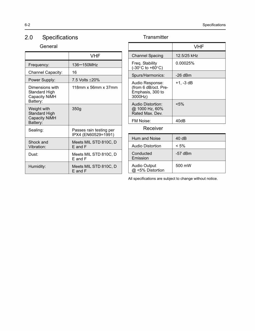
2.0 SpecificationsGeneral
Transmitter
Receiver
All specifications are subject to change without notice.
VHF
Frequency: 136–150MHz
Channel Capacity: 16
Power Supply: 7.5 Volts ±20%
Dimensions with Standard High Capacity NiMH Battery:
118mm x 56mm x 37mm
Weight with Standard High Capacity NiMH Battery:
350g
Sealing: Passes rain testing per IPX4 (EN60529=1991)
Shock and Vibration:
Meets MIL STD 810C, D E and F
Dust: Meets MIL STD 810C, D E and F
Humidity: Meets MIL STD 810C, D E and F
VHF
Channel Spacing 12.5/25 kHz
Freq. Stability(-30°C to +60°C)
0.00025%
Spurs/Harmonics: -26 dBm
Audio Response:(from 6 dB/oct. Pre-Emphasis, 300 to 3000Hz)
+1, -3 dB
Audio Distortion:@ 1000 Hz, 60%Rated Max. Dev.
<5%
FM Noise: 40dB
Hum and Noise 40 dB
Audio Distortion < 5%
Conducted Emission
-57 dBm
Audio Output@ <5% Distortion
500 mW
VHF Band 2 Information (150 – 174 MHz) 6-3
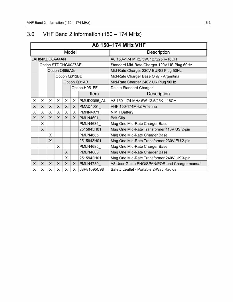
3.0 VHF Band 2 Information (150 – 174 MHz)
A8 150–174 MHz VHF Model Description
LAH84KDC8AA4AN A8 150–174 MHz, 5W, 12.5/25K–16CHOption STDCHG0027AE Standard Mid-Rate Charger 120V US Plug 60Hz
Option Q665AG Mid-Rate Charger 230V EURO Plug 50HzOption Q312BD Mid-Rate Charger Base Only - Argentina
Option Q91AB Mid-Rate Charger 240V UK Plug 50HzOption H951FF Delete Standard Charger
Item DescriptionX X X X X X PMUD2085_AL A8 150–174 MHz 5W 12.5/25K - 16CHX X X X X X PMAD4051_ VHF 150-174MHZ AntennaX X X X X X PMNN4071_ NiMH BatteryX X X X X X PMLN4691_ Belt Clip
X PMLN4685_ Mag One Mid-Rate Charger BaseX 2515945H01 Mag One Mid-Rate Transformer 110V US 2-pin
X PMLN4685_ Mag One Mid-Rate Charger BaseX 2515943H01 Mag One Mid-Rate Transformer 230V EU 2-pin
X PMLN4685_ Mag One Mid-Rate Charger BaseX PMLN4685_ Mag One Mid-Rate Charger BaseX 2515942H01 Mag One Mid-Rate Transformer 240V UK 3-pin
X X X X X X PMLN4739_ A8 User Guide ENG/SPAN/POR and Charger manualX X X X X X 68P81095C98 Safety Leaflet - Portable 2-Way Radios

6-4 Specifications
4.0 Specifications General
Transmitter
Receiver
All specifications are subject to change without notice.
VHF
Frequency: 150-174 MHz
Channel Capacity: 16
Power Supply: 7.5 Volts ±20%
Dimensions with Standard High Capacity NiMH Battery:
118mm x 56mm x 37mm
Weight with Standard High Capacity NiMH Battery:
350g
Sealing: Passes rain testing per IPX4 (EN60529=1991)
Shock and Vibration:
Meets MIL STD 810C, D E and F
Dust: Meets MIL STD 810C, D E and F
Humidity: Meets MIL STD 810C, D E and F
VHF
Channel Spacing 12.5/25 kHz
Freq. Stability(-30°C to +60°C)
0.00025%
Spurs/Harmonics: -26 dBm
Audio Response:(from 6 dB/oct. Pre-Emphasis, 300 to 3000Hz)
+1, -3 dB
Audio Distortion:@ 1000 Hz, 60%Rated Max. Dev.
<5%
FM Noise: 40dB
Hum and Noise 40 dB
Audio Distortion < 5%
Conducted Emission
-57 dBm
Audio Output@ <5% Distortion
500 mW
UHF Band 1 Information (403-425MHz) 6-5
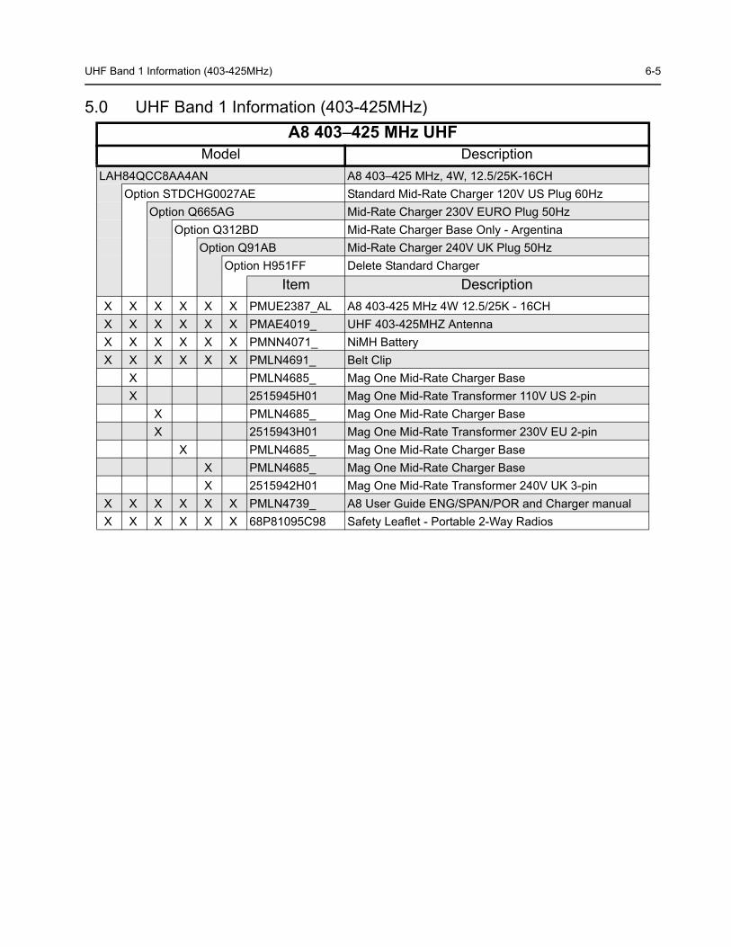
5.0 UHF Band 1 Information (403-425MHz) A8 403–425 MHz UHF
Model DescriptionLAH84QCC8AA4AN A8 403–425 MHz, 4W, 12.5/25K-16CH
Option STDCHG0027AE Standard Mid-Rate Charger 120V US Plug 60HzOption Q665AG Mid-Rate Charger 230V EURO Plug 50Hz
Option Q312BD Mid-Rate Charger Base Only - ArgentinaOption Q91AB Mid-Rate Charger 240V UK Plug 50Hz
Option H951FF Delete Standard ChargerItem Description
X X X X X X PMUE2387_AL A8 403-425 MHz 4W 12.5/25K - 16CHX X X X X X PMAE4019_ UHF 403-425MHZ AntennaX X X X X X PMNN4071_ NiMH BatteryX X X X X X PMLN4691_ Belt Clip
X PMLN4685_ Mag One Mid-Rate Charger BaseX 2515945H01 Mag One Mid-Rate Transformer 110V US 2-pin
X PMLN4685_ Mag One Mid-Rate Charger BaseX 2515943H01 Mag One Mid-Rate Transformer 230V EU 2-pin
X PMLN4685_ Mag One Mid-Rate Charger BaseX PMLN4685_ Mag One Mid-Rate Charger BaseX 2515942H01 Mag One Mid-Rate Transformer 240V UK 3-pin
X X X X X X PMLN4739_ A8 User Guide ENG/SPAN/POR and Charger manualX X X X X X 68P81095C98 Safety Leaflet - Portable 2-Way Radios

6-6 Specifications
6.0 Specifications
General
Transmitter
Receiver
All specifications are subject to change without notice.
UHF
Frequency: 403-425MHz
Channel Capacity: 16
Power Supply: 7.5 Volts ±20%
Dimensions with Standard High Capacity NiMH Battery:
107mm x 58mm x 37mm
Weight: with Standard High Capacity NiMH Battery:
350g
Sealing: Passes rain testing per IPX4 (EN60529=1991)
Shock and Vibration:
Meets MIL STD 810C, D E and F
Dust: Meets MIL STD 810C, D E and F
Humidity: Meets MIL STD 810C, D E and F
UHF
Channel Spacing 12.5/25 kHz
Freq. Stability(-30°C to +60°C)
0.00025%
Spurs/Harmonics: -27 dBm
Audio Response:(from 6 dB/oct. Pre-Emphasis, 300 to 3000Hz)
+1, -3 dB
Audio Distortion:@ 1000 Hz, 60%Rated Max. Dev.
<5%
FM Noise: 40dB
Hum and Noise 40 dB
Audio Distortion < 5%
Conducted Emission
-57 dBm
Audio Output@ <5% Distortion
500mW
UHF Band 2 Information (450 – 470MHz) 6-7
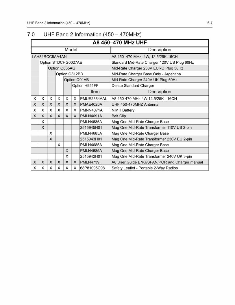
7.0 UHF Band 2 Information (450 – 470MHz) A8 450–470 MHz UHF
Model DescriptionLAH84RCC8AA4AN A8 450–470 MHz, 4W, 12.5/25K-16CH
Option STDCHG0027AE Standard Mid-Rate Charger 120V US Plug 60HzOption Q665AG Mid-Rate Charger 230V EURO Plug 50Hz
Option Q312BD Mid-Rate Charger Base Only - ArgentinaOption Q91AB Mid-Rate Charger 240V UK Plug 50Hz
Option H951FF Delete Standard ChargerItem Description
X X X X X X PMUE2384AAL A8 450-470 MHz 4W 12.5/25K - 16CHX X X X X X PMAE4020A UHF 450-470MHZ AntennaX X X X X X PMNN4071A NiMH BatteryX X X X X X PMLN4691A Belt Clip
X PMLN4685A Mag One Mid-Rate Charger BaseX 2515945H01 Mag One Mid-Rate Transformer 110V US 2-pin
X PMLN4685A Mag One Mid-Rate Charger BaseX 2515943H01 Mag One Mid-Rate Transformer 230V EU 2-pin
X PMLN4685A Mag One Mid-Rate Charger BaseX PMLN4685A Mag One Mid-Rate Charger BaseX 2515942H01 Mag One Mid-Rate Transformer 240V UK 3-pin
X X X X X X PMLN4739_ A8 User Guide ENG/SPAN/POR and Charger manualX X X X X X 68P81095C98 Safety Leaflet - Portable 2-Way Radios

6-8 Specifications
8.0 Specifications
General
Transmitter
Receiver
All specifications are subject to change without notice.
UHF
Frequency: 450-470 MHz
Channel Capacity: 16
Power Supply: 7.5 Volts ±20%
Dimensions with Standard High Capacity NiMH Battery:
107mm x 58mm x 37mm
Weight: with Standard High Capacity NiMH Battery:
350g
Sealing: Passes rain testing per IPX4 (EN60529=1991)
Shock and Vibration:
Meets MIL STD 810C, D E and F
Dust: Meets MIL STD 810C, D E and F
Humidity: Meets MIL STD 810C, D E and F
UHF
Channel Spacing 12.5/25 kHz
Freq. Stability(-30°C to +60°C)
0.00025%
Spurs/Harmonics: -27 dBm
Audio Response:(from 6 dB/oct. Pre-Emphasis, 300 to 3000Hz)
+1, -3 dB
Audio Distortion:@ 1000 Hz, 60%Rated Max. Dev.
<5%
FM Noise: 40dB
Hum and Noise 40 dB
Audio Distortion < 5%
Conducted Emission
-57 dBm
Audio Output@ <5% Distortion
500mW
UHF Band 4 Information (490 - 512 MHz) 6-9
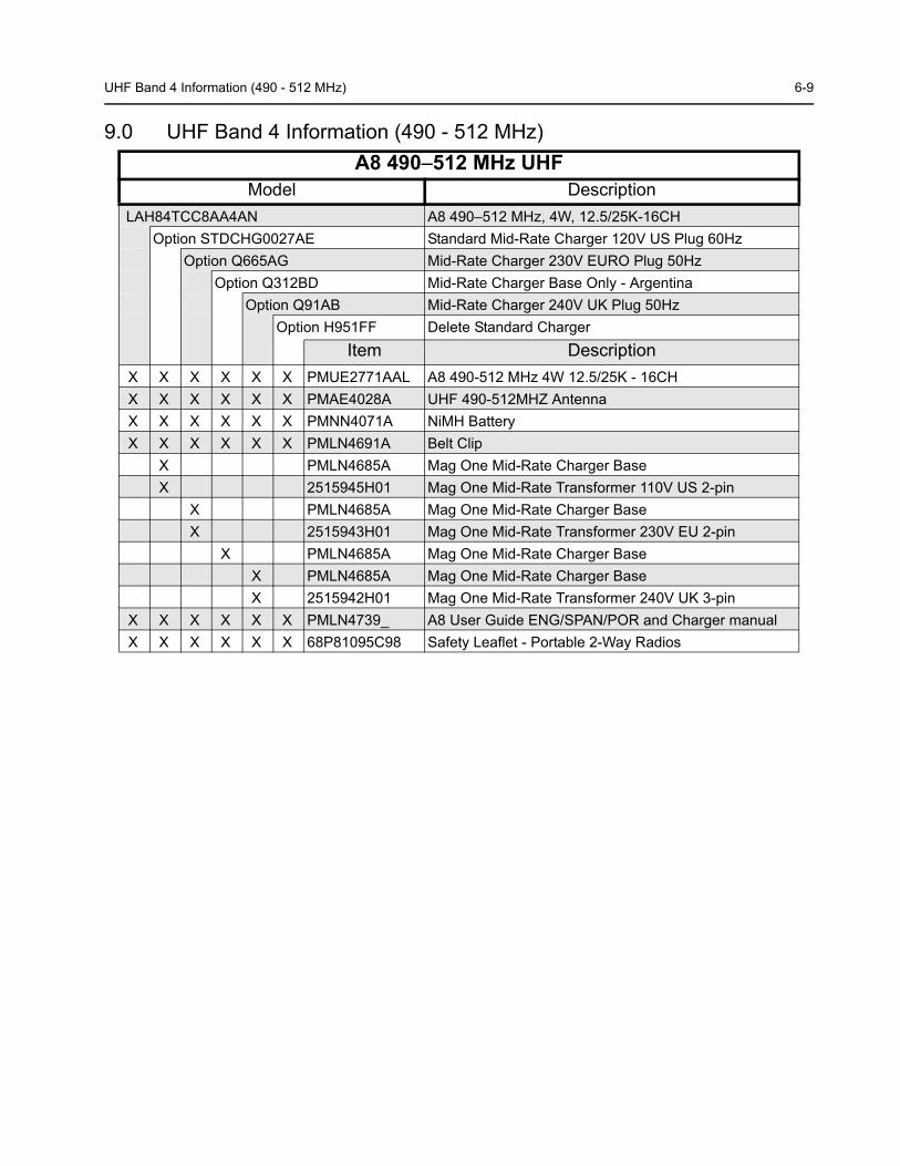
9.0 UHF Band 4 Information (490 - 512 MHz) A8 490–512 MHz UHF
Model Description LAH84TCC8AA4AN A8 490–512 MHz, 4W, 12.5/25K-16CH
Option STDCHG0027AE Standard Mid-Rate Charger 120V US Plug 60HzOption Q665AG Mid-Rate Charger 230V EURO Plug 50Hz
Option Q312BD Mid-Rate Charger Base Only - ArgentinaOption Q91AB Mid-Rate Charger 240V UK Plug 50Hz
Option H951FF Delete Standard ChargerItem Description
X X X X X X PMUE2771AAL A8 490-512 MHz 4W 12.5/25K - 16CHX X X X X X PMAE4028A UHF 490-512MHZ AntennaX X X X X X PMNN4071A NiMH BatteryX X X X X X PMLN4691A Belt Clip
X PMLN4685A Mag One Mid-Rate Charger BaseX 2515945H01 Mag One Mid-Rate Transformer 110V US 2-pin
X PMLN4685A Mag One Mid-Rate Charger BaseX 2515943H01 Mag One Mid-Rate Transformer 230V EU 2-pin
X PMLN4685A Mag One Mid-Rate Charger BaseX PMLN4685A Mag One Mid-Rate Charger BaseX 2515942H01 Mag One Mid-Rate Transformer 240V UK 3-pin
X X X X X X PMLN4739_ A8 User Guide ENG/SPAN/POR and Charger manualX X X X X X 68P81095C98 Safety Leaflet - Portable 2-Way Radios
6-10 Specifications
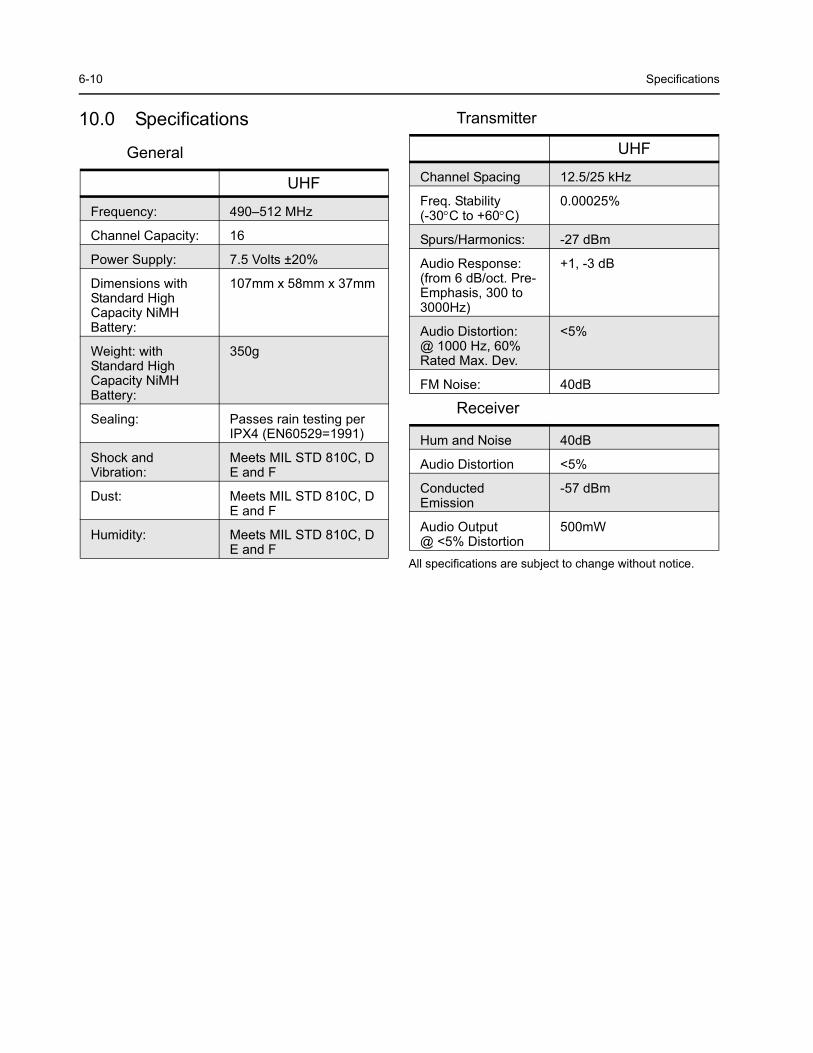
10.0 Specifications
General
Transmitter
Receiver
All specifications are subject to change without notice.
UHF
Frequency: 490–512 MHz
Channel Capacity: 16
Power Supply: 7.5 Volts ±20%
Dimensions with Standard High Capacity NiMH Battery:
107mm x 58mm x 37mm
Weight: with Standard High Capacity NiMH Battery:
350g
Sealing: Passes rain testing perIPX4 (EN60529=1991)
Shock and Vibration:
Meets MIL STD 810C, DE and F
Dust: Meets MIL STD 810C, DE and F
Humidity: Meets MIL STD 810C, DE and F
UHF
Channel Spacing 12.5/25 kHz
Freq. Stability(-30°C to +60°C)
0.00025%
Spurs/Harmonics: -27 dBm
Audio Response:(from 6 dB/oct. Pre-Emphasis, 300 to 3000Hz)
+1, -3 dB
Audio Distortion:@ 1000 Hz, 60%Rated Max. Dev.
<5%
FM Noise: 40dB
Hum and Noise 40dB
Audio Distortion <5%
Conducted Emission
-57 dBm
Audio Output@ <5% Distortion
500mW
G-1
GLOSSARY OF TERMS
Term Definition
Busy Channel Lockout (BCLO)
If BCLO is activated, the radio will check for channel activity before transmit-ting. If activity is detected, transmission is prohibited. For carrier squelch mode, radio will not transmit, if it is receiving carrier. For coded squelch mode, it will not transmit, if it is receiving carrier with different PL/DPL code.
Carrier An electromagnetic signal that is transmitted on a selected frequency for the purpose of carrying voice or data transmissions along with it. Carrier can then be received by all radios listening on that frequency.
CD Compact Disk.
Channel A single path separated by frequency or time divisions used for transmitting and/or receiving voice and/or data.
Codeplug A solid-state chip inside a radio where the radio’s personality data is stored.
CPS Acronym for Customer Programming Software. Licensed Motorola software used to program two-way radios with a unique set of features.
Frequency (a) The location of the center of a channel of operation in the radio spectrum. Measured in Megahertz (MHz).(b) A computer speed. Measured in Megahertz (MHz).
Model Number The model number identifies the type of radio. This information is stored in the radio’s codeplug.
Normal Scan For Normal Scan, the radio assigns equal priority to all members in the Scan List selected for the current channel. When the radio is scanning a Scan List (Active Scan), all scan list members (including the Home Channel) will be allo-cated equal time to be scanned. For example, if the Home Channel is H1, and the Scan List Members are Nn, then the scanning sequence is: N1, N2, N3, ..., H1, N1, N2, ..., etc.
PLL Phase-Locked Loop: a circuit in which an oscillator is kept in phase with a ref-erence, usually after passing through a frequency divider.
Priority Scan For Priority Scan, the radio assigns the highest priority to the channel defined in the CPS as Priority Channel. When the radio is scanning a Scan List (Active Scan), 50% of the scans are targeted at the Priority Channel. For example, if the Priority Channel is P1, and the non-priority Scan List Members are Nn, then the scanning sequence is: P1, N1, P1, N2, P1, N3, P1, N4, P1, N5, etc.
Program The transfer of CPS information from the computer’s temporary memory (RAM) to the radio.
PTT Push-To-Talk: the switch located on the left side of the radio which, when pressed, causes the radio to transmit.
RESET Reset line: an input to the microcontroller that restarts execution.
Reverse Burst / Turn Off Code
Causes a Tone Private Line (TPL) or Digital Private Line (DPL) code to be transmitted at the end of a transmission - once PTT is released, and while op-erating on the current channel. This sub-audible tone causes the receiving ra-dio to mute its speaker before loss of a carrier is detected. Muting the speaker eliminates unwanted noise (squelch tail) during loss of carrier detection.
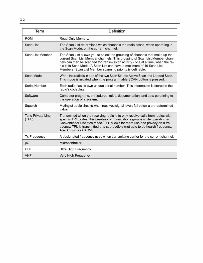
G-2
ROM Read Only Memory.
Scan List The Scan List determines which channels the radio scans, when operating in the Scan Mode, on the current channel.
Scan List Member The Scan List allows you to select the grouping of channels that make up the current Scan List Member channels. This grouping of Scan List Member chan-nels can then be scanned for transmission activity - one at a time, when the ra-dio is in Scan Mode. A Scan List can have a maximum of 16 Scan List Members. Scan List Member scanning priority is definable.
Scan Mode When the radio is in one of the two Scan States: Active Scan and Landed Scan. This mode is initiated when the programmable SCAN button is pressed.
Serial Number Each radio has its own unique serial number. This information is stored in the radio’s codeplug.
Software Computer programs, procedures, rules, documentation, and data pertaining to the operation of a system.
Squelch Muting of audio circuits when received signal levels fall below a pre-determined value.
Tone Private Line (TPL)
Transmitted when the receiving radio is to only receive calls from radios with specific TPL codes, this creates communications groups while operating in Conventional Dispatch mode. TPL allows for more use and privacy on a fre-quency. TPL is transmitted at a sub-audible (not able to be heard) frequency. Also known as CTCSS.
Tx Frequency A designated frequency used when transmitting carrier for the current channel.
µC Microcontroller.
UHF Ultra High Frequency.
VHF Very High Frequency.
Term Definition

©2007 by Motorola, Inc. All rights reserved.Mag One by Motorola is registered in the U.S. Patent and Trademark Office. All other product or service names are the property of their respective owners.
Motorola, Inc.8000 West Sunrise BoulevardPlantation, FL 33322U.S.A.
March, 2007


