CHASSIS AND BODY MAINTENANCE ........................................................................................ MA-31
SERVICE DATA AND SPECIFICATIONS (S.D.S.) .................................................................... MA-42
PREPARATION
SPECIAL SERVICE TOOL
Tool number Description Tool name
EG 17650301 Adapting radiator cap tester to Radiator cap tester radiator filler neck adapter
PRE-DELIVERY INSPECTION ITEMS
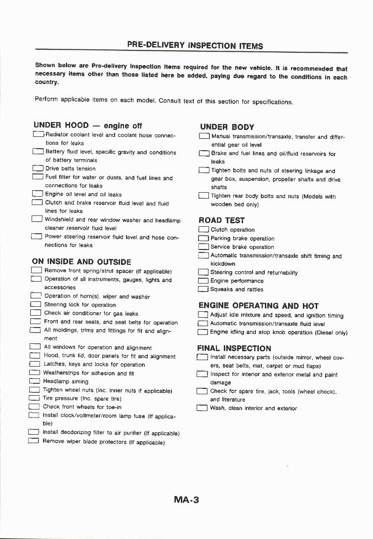
Shown below are Pre-delivery Inspection Items required for the new vehicle. It is recommended that necessary items other than those listed here be added, paying due regard to the conditions in each . country.
Perform applicable items on each model. Consult text of this section for specifications.
UNDER HOOD - engine off 0 Radiator coolant level and coolant hose connec-
tions for leaks 0 Battery fluid level, specific gravity and conditions
of battery terminals 0 Drive belts tension
Fuel filter for water or dusts, and fuel lines and connections for leaks 0 Engine oil level and oil leaks 0 Clutch and brake reservoir fluid level and fluid
lines for leaks ( Windshield and rear window washer and headlamp
cleaner reservoir fluid level 0 Power steering reservoir fluid level and hose con-
nections for leaks
ON INSIDE AND OUTSIDE 0 Remove front springlstrut spacer (If applicable) 0 Operation of all instruments, gauges, lights and
accessories 0 Operation of horn@), wiper and washer 0 Steering lock for operation 0 Check air conditioner for gas leaks
0 Front and rear seats, and seat belts for operation 0 All moldings, trims and fittings for fit and align-
ment 1 All windows for operation and alignment 0 Hood, trunk lid, door panels for fit and alignment
0 I t ches , keys and locks for operation
0 Weatherstrips for adhesion and fit
0 Headlarnp aiming a Tighten wheel nuts (lnc. inner nuts if applicable) 0 Tire pressure (Inc. spare tire)
Check front wheels for toe-in 0 Install clock/voltmeter/room lamp fuse (If applica-
ble) 0 Install deodorizing filter to air purifier (If applicable)
0 Remove wiper blade protectors (If applicable)
UNDER BODY 0 Manual transmissionltransaxle, transfer and differ-
ential gear oil level ( Brake and fuel lines and oil/fluid reservoirs for
leaks
0 Tighten bolts and nuts of steering linkage and gear box, suspension, propeller shafts and drive
shafts Tighten rear body bolts and nuts (Models with
wooden bed only)
ROAD TEST 0 Clutch operation 0 Parking brake operation ( Service brake operation 0 Automatic transmission/transaxle shift timing and
kickdown 0 Steering control and returnability 1 Engine performance
0 Squeaks and rattles
ENGINE OPERATING AND HOT 0 Adjust idle mixture and speed, and ignition timing 0 Automatic transmission/transaxle fluid level 0 Engine idling and stop knob operation (Diesel only)
FINAL INSPECTION 0 Install necessary parts (outside mirror, wheel cov-
ers, seat belts, mat, carpet or mud flaps) 0 Inspect for interior and exterior metal and paint
damage Check for spare tire, jack, tools (wheel chock), and literature
( Wash, clean interior and exterior
MAINTENANCE SCHEDULE
The following tables show the normal maintenance schedule. Depending upon weather and a t m o s p h e r i c
conditions, varying road surfaces, individual driving habits and vehicle usage, additional or more frequent m a i n t e n a n c e may b e required. Periodic maintenance beyond the last period shown on the tables requires similar maintenance.
MAINTENANCE OPERATION MAINTENANCE INTERVAL
Perform either at number of kilometen km x 1,000 1 10 20 30 40 50 60 70 80 Reference (miles) or months, whichever comes first. (Miles x 1,000) (0.61 (6) (121 (181 (241 (30) (36) (421 (481 Page
Months - 6 12 18 24 30 36 42 48
ENGINE AND EMISSION CONTROL MAINTENANCE Underhood and under vehicle - - - - - - - - - - Gasoline i Diesel
Adjust intake & exhaust valve clearances X X X X X MA-10 i MA-21
Check drive belts for cracks, fraying, wear & tension X X X X X MA-11 MA-22
Chanae enaine anti-freeze coolant (Ethvlene alvcol bare. L.L.C.) X X MA-12 MA-23 -
Change engtne coolant (Soft waterl.1 X X X X X X X X MA-12;MA-23
Check cooltng system X X X X MA-13 ; MA-24
Check fuel l~nes X X MA-13 i MA-26
Clean & replace atr cleaner f~lter (Dry paper typel'l Clean* X X X X X X MA-14 : MA-26
Renlace* X X MA.14 ' MA-26 .- --- -. Replace air cleaner filter (VISCOUS paper type)* X X Check cyclone preatr cleaner* X X
Change engine oil (Use API SE or SF oil.) & oil filterr X X X X X X X X Check & adjust idle rpm & mixture ratio (Check mixture ratio only on models bound for areas affected by emission X X't X X'1 X X * l X X O l X regulations.) EF & EC-36
Adiust ianition timina X'1 X X'1 X X * l X X O l X - - - - -
R- hral fltta~Y X X MA-14
Check & replace distributor breaker point Check'l X X X X MA-16 I 0
Replace X X X X MA-16 Z Check & replace spark plugs Check.1 X X X X MA-17 W W Rmlace X X X X MA.17 .-.-. -. . - - . .. .. z_ _I Check ignition wires X X MA-18
Check choke mechanisn (Choke plate & links9e)*2 X X X X MA-18
5 Check positive crankcase ventilation (P.C.V.1 system X X X X MA-18 Replace P.C.V. filtem X X MA-19 Check vacuum hoses & connections X X X X MA-19
Check automatic tennerature control air cleaner X X X X MA-19
Check vapor lines (Hoses, connections, etc.) (Australia & Gulf standard models only) X X MA-19
Check E.G.R. control s y s m (Gulf standard models with A f f only) X X X X MA-20
Check fuel filter & drain water.2 X X X X X X M A S
u Reolace fuel filtem X X MA-25 - - .. . -. 2 .
Change engine oil (Use API CC or CD oil.)* Every 5,000 krn (3.000 miles) or 3 months MA-22
2 Cbqeoi l43mm X X X X X - X X X MA-23 Check nozzle See NOTE ( 1 I. MA-27
Check idlina swed X X X X X MA-% - - - . -- 0 Dram oil & lubricate diaphragm
(Governor chanber for lnject~on pumpl'l X X X X X X X X MA-23
NOTE: (1) If engine power decreases, black exhaust smoke is emitted or engine noise inereass, check and, if necessary, adjust the fuel injection node's starting pauure and the fuel spray pattern.
(2) Maintenance items with 'u' should be performed more frequently according to "Maintenance under revere driving conditions".
Check: Check. Correct or replace if necessary. "1: NonAustralia models only *2: Australia models only
MAINTENANCE SCHEDULE
MAINTENANCE OPERATION MAINTENANCE INTERVAL
Perform either at number of kilometen km x 1,000 1 10 20 30 40 50 60 70 80 Reference
(miles) ormonths, whichever comes fiat. (Miles x 1,000) (0.6) (6) (121 (18) (241 (30) (38) (421 (48) page -
~ - - . Months - 6 12 18 24 30 36 42 48
CHASSIS AND BODY MAINTENANCE Undehoad
Check brake. clutch, automatic transmission & steering gear fluid MA31.32, or oil level & for leaks* x x x x x x x x 36.39
Change brake fluid* X X . MA37
Check brake booster vacuum hoses, connections & check valve X x MA37
Check power steering fluid & lines X X X X X X X X M A 3 9
Under vehide Check brake. clutch, exhaust systems for proper attachment, leaks, cracks, chafing, abrasion, deterioration, etc. X X X X X X X X MA31.36
C h k oil level & chanae oil in manual transmission. Check X X X X X Y MA31.33.34 transfer & differential gear
. - - - .- .- .. -- -- -- . . Chanae X X MA31.33.35
- - - - - -
Grease greasing points of steering linkage & propeller shaft* X X X X X X X X MA34.40
Chack steering gear box & linkage, axle & suspension parts & propeller shaft for damaged, loose & missing parts X X X X X X X X X & lubrication*
Check steering damper X X X X
Retighten body mountings X X X X X
Ouakb and Enddo Check wheel alignment. If necessary, rotate & balance wheels X X X X
Check brake pads, discs & other brake components for wear, deterioration & leaks* X X X X X X X X
Check brake linings, drums & other brake components for wear. deterioration & leaks* X X X X
Check front wheel bearing grease & free-running hub graass* X X Repack front wheel bearing & front axle joint grease. & check free-runnina hub arease X X - - - - Lubricate locks, hinges & hood latch* X X X X X X X X
Check seat belts, buckles, retractors, anchors & adiuster X X X X
Check foot brake, parking brake & clutch for free play, CL-5 & X X X X X X X X B R S
stroke & operation
NOTE: Maintenance items with 'w' shauld be performed more frequentty according to "'Maintenance under severe driving conditions".
Check: Check. Correct or replace if necessary.
MA- 5
MAINTENANCE UNDER SEVERE DRIVING CONDITIONS The maintenance intervals shown on the preceding pages are for normal operating conditions. If the vehicle is mainly operated under severe driving conditions as shown below, more frequent maintenance is required to be performed on the following items as shown in the table.
Severe driving conditions A - Driving under dusty conditions B - Driving repeatedly short distances C - Towing a trailer D - Extensive idling E - Driving in extremely adverse weather conditions or in areas where ambient temperatures are either
extremely low or extremely high F - Driving in high humidity areas or in mountainous areas G - Driving in areas using salt or other corrosive materials H - Driving on rough and/or muddy roads or in the desert I - Frequent driving in water
Maintenance operation: Check - Check. Correct or replace i f necessary.
MAINTENANCE SCHEDULE
Maintenance for off-road driving Whenever you drive off-road through sand, mud or water as deep as the wheel hub, more frequent maintenance may be required of the following items: A Brake pads and discs A Brake lining and drums A Brake lines and hoses A Wheel bearing grease and free-running hub grease A Differential, transmission and transfer oil A Steering linkage A Propeller shafts A Air cleaner filter A Clutch housing and knuckle flange (Check water entry. Refer to MA-32 8 36.)
RECOMMENDED LUBRICANTS
Lubricants
Capacity (Approximate) Recommended lubricants
Liter Imp measure
Engine oil (Refill) With oil filter
Gasoline engine: API SE or SF* 1
Without oil filter Diesel engine: TB42 7.7 6-314 qt API CC or CD* 1
Cooling system (With reservoir tank) With heater
TB42 M/T 13.9 12-114 qt TB42 A n 13.6 12 qt TD42 M/T 13.6 12 qt Anti-freeze coolant
Without heater (Ethylene glycol base) or soft water
TB42 MIT 13.3 1 1-314 qt TB42 A n 13.0 11 -112 qt TD42 M/T 12.8 11-114 qt
Cooling system 11-112 qt Anti-freeze coolant (Ethylene glycol base) or soft water
Auto free-running hub grease Nissan genuine grease (Part No.: KRC19-00025) or equivalent
- -
'1 : For further details, see "SAE Viscosity Number". '2: API GL-5, SAE 140 and 10% volume of L.S.D. friction modifier (Part No.: 38469-C6000) or equivalent.
RECOMMENDED LUBRICANTS
SAE Outside Temperature R w Anticipated Before Next Oil Change
GASOLINE ENGINE OIL
----------
Not recommended for sustained high
- speed driving
Visc osity Number Outside Temperature Range Anticipated Before Next Oil Change
m For warm and cold areas: 10W-30 is prefera- ble for ambient temperatures above -20°C (-4OF).
a For hot areas: 20W-40 and 20W-50 are suita- ble.
DIESEL ENGINE OIL
GEAR OIL I
j For warm and cold areas: 75W-90 fortrans- mission of gasoline engine model and trans- fer, 80W-90 for differential carrier and 90 for transmission of diesel engine model are preferable. For hot areas: 90 is suitable for ambient temperatures below 40°C (104OF).
For cold areas: 10W-30 is preferable. For hot and warm areas: 20W40 and 20W-50 are suitable.
ENGINE MAINTENANCE l E l
lntake side
Tighten in numerical order.
SMA872B
Exhaust side
Tighten in numerical order. SMA873B
Tighten in numerical order.
SMA891B
Checking Tightening Torque Checking should be performed while engine is cold.
Adjusting lntake and Exhaust Valve Clearance Adjustment should be made while engine is warm but not running. 1. Set No. 1 cylinder at top dead center on its compression
stroke, and adjust valve clearances @, 0, 0, @, @ and @. 2. Set No. 6 cylinder at top dead center on its compression
stroke, and adjust valve clearances @, 0, @, @, @I and 0. Valve clearance:
Inspect drive belt deflections when engine is cold.
ENGINE MAINTENANCE ITeu]
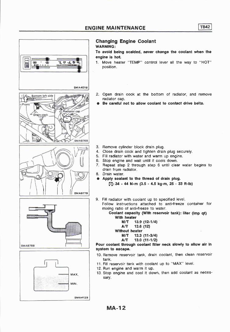
Changing Engine Coolant WARNING: To avoid being scalded, never change the coolant when the engine is hot. 1. Move heater "TEMP" control lever all the way to "HOT"
position.
MAX.
MIN.
SMA412B
2. Open drain cock at the bottom of radiator, and remove radiator cap.
a Be careful not to allow coolant to contact drive belts.
3. Remove cylinder block drain plug. 4. Close drain cock and tighten drain plug securely. 5. Fill radiator with water and warm up engine. 6. Stop engine and wait until it cools down. 7. Repeat step 2 through step 6 until clear water begins to
drain from radiator. 8. Drain water. a Apply sealant to the thread of drain plug.
(ol: 34 - 44 N-m (3.5 - 4.5 kg-m, 25 - 33 ft-lb)
9. Fill radiator with coolant up to specified level. Follow instructions attached to anti-freeze container for mixing ratio of anti-freeze to water.
Coolant capacity w i th reservoir tank): liter (Imp qt) With heater
M/l 13.9 (12-1/4) '
A/T 13.6 (12) Without heater
M n 13.3 (11-314) A K 13.0 (1 1-1 12)
Pour coolant through coolant filler neck slowly to allow air in system to escape.
10. Remove reservoir tank, drain coolant, then clean reservoir tank.
11. Fill reservoir tank with coolant up to "MAX" level. 12. Run engine and warm it up. 13. Stop engine and cool it down, then add coolant as neces-
sary.
ENGINE MAINTENANCE l3!El Checking Cooling System CHECKING HOSES Check hoses for proper attachment and for leaks, cracks, damage, loose connections, chafing and deterioration.
CHECKING RADIATOR CAP Apply pressure to radiator cap with cap tester to see if it is satisfactory.
Radiator cap relief pressure: 78 - 98 kPa (0.78 - 0.98 bar, 0.8 - 1.0 kg/cm2, 11 - 14 psi)
Pull the negative-pressure valve to open it. Check that it closes completely when released.
CHECKING COOLING SYSTEM FOR LEAKS Apply pressure to the cooling system with cap tester to check for leakage.
Testing pressure: 98 kPa (0.98 bar, 1.0 kg/cm2, 14 psi)
CAUTION: Higher pressure than the specified value may cause damage to radiator.
Checking Fuel Lines Inspect fuel lines and tank for proper attachment and for leaks, cracks, damage, loose connections, chafing and deterioration. If necessary, repair or replace faulty parts.
ENGINE MAINTENANCE lz!El Checking Fuel Lines (Cont'd) CAUTION: Tighten high-pressure rubber hose clamp so that clamp end is 3 mm (0.12 in) from hose end. Tightening torque specifications are the same for all rubber hose clamps. Ensure that screw does not contact adjacent parts.
Changing Fuel Filter Be careful not to spill fuel over engine compartment. Place a shop towel to absorb fuel.
Cleaning and Changing Air Cleaner Filter Viscous paper type The viscous paper type filter does not need cleaning between renewals.
Dry paper type It is necessary to clean the element or replace it at the recommended intervals, more often under dusty driving condi- tions.
To properly tighten wing nuts, position clamps at four places and tighten wing nuts until they touch air cleaner. Then tighten them three more turns.
ENGINE MAINTENANCE E!il Checking Cyclone Pre-air Cleaner Remove dust cover and check duct for dust clogging. Clean away any dust.
Changing Engine Oil WARNING: Be careful not to burn yourself, as the engine oil is hot. 1. Warm up engine, and check for oil leakage from engine
components. 2. Remove drain plug and oil filler cap. 3. Drain oil and refill with new engine oil. Refill oil capacity (Approximate):
Unit: liter (Imp qt)
1 With oil filter change 8.2 (7-114)
Without oil filter change 7.7 (83/4)
CAUTION: Be sure to clean drain plug and install with new washer.
4. Check oil level. 5. Start engine and check area around drain plug and oil filter
for oil leakage. 6. Run engine for a few minutes, then turn it off. After several
minutes, check oil level.
Refill oil to "H" level. Do not overfill.
Changing Oil Filter 1. Remove oil filter with a suitable tool.
WARNING: Be careful not to burn yourself, as the engine and the engine oil are hot.
2. Before installing new oil filter, clean the oil filter mounting surface on cylinder block, and coat the rubber seal of oil filter with a little engine oil.
3. Screw in the oil filter until a slight resistance is felt, then tighten additionally more than 213 turn.
4. Add engine oil. Refer to Changing Engine Oil.
Checking and Changing Distributor Breaker Point VISUAL CHECK 1. Check poins for excessive burning or pitting. 2. Use a point file to clean contact area and remove scale from
points. Do not attempt to remove all roughness.
POINT GAP 1. Set contact point on the nose of cam, and check point gap
with oilless feeler gauge. Point gap:
0.45 - 0.55 mm (0.018 - 0.022 in) 2. If out of specification, loosen contact point plate set screw
and adjust point gap by pivoting projected pin.
W~de polnt gap kF Small dwell
The w~der point gap, the smaller dwell mgk.
Nurow Point gap kF Large dwell
The narrower point gap, the larger dwell angle.
SMA474
ENGINE MAINTENANCE I 3 Checking and Changing Distributor Breaker Point (Cont'd) DWELL ANGLE 1. Start engine and warm it up. 2. Run engine at idle speed and measure dwell angle with a
dwell meter. Dwell angle: 34O - 40°
3. If dwell angle is not within the specified value turn off engine and adjust point gap.
4. If dwell angle is not within the specified value when point gap is correct, cam lobe is worn. replace cam.
DISTRIBUTOR BREAKER POINT 1. Install new set and adjust point gap and dwell angle. 2. Apply the specified grease to cam and cam head.
Checking and Changing Spark Plugs 1. Disconnect ignition wires from spark plugs at boot. Do not
pull on the wire. 2. Remove spark plugs with spark plug wrench. 3. Clean plugs in sand blast cleaner. 4. Check insulator for cracks or chips, gasket for damage or
deterioration and electrode for wear and burning. If they are excessively worn away, replace with new spark plugs.
Gap: 0.8 - 0.9 mm (0.031 - 0.035 in) 6. Install spark plugs. Reconnect ignition wires according to
Nos. indicated on them. m: Spark plug
20 - 29 Nom (2.0 - 3.0 kg-m, 14 - 22 ft-lb)
Checking Ignition Wires 1. Inspect wires for cracks, damage, burned terminals and for
improper fit. 2. Measure the resistance of wires and check for intermittent
breaks by shaking them. Resistance: Less than 30 kS2
If it exceeds the limit, replace the ignition wire with a new one.
Checking Choke Mechanism 1. When engine is shut off and cold, check choke valve and
mechanism to make sure that they operate freely. (1) Fully open throttle valve and insure that choke valve closes
properly. (2) Push choke valve and, check it for binding or unsmooth
movement. 2. Check that bimetal cover index mark is set at the choke
housing index mark. 3. Start engine and run it at idle. Check to see if choke valve
gradually opens approaching full open as engine warms up.
Checking Positive Crankcase Ventilation (P.C.V.) System CHECKING P.C.V. VALVE With engine running at idle, remove ventilation hose from rocker cover; if valve is working properly, a hissing noise will be heard as air passes through it and a strong vacuum should be felt immediately when a finger is placed over valve inlet.
CHECKING VENTILATION HOSES 1. Check hoses and hose connections for leaks. 2. Disconnect all hoses and clean with compressed air. If any
hose cannot be freed of obstructions, replace.
MA- 1 8
ENGINE MAINTENANCE 178421 Changing Positive Crankcase Ventilation (P.C.V.) Filter Remove air cleaner cover and replace P.C.V. filter.
Checking Vacuum Hoses and Connections Check vacuum hoses for improper attachment and for leaks, cracks, damage, loose connections, chafing and deterioration.
To air temperature
Hot air from exhaust manifold cover SMA890B
Checking Automatic Temperature Control (A.T.C.) Air Cleaner
1. lnspect vacuum hoses (Intake manifold to temperature sensor and vacuum motor) for secure connections.
2. Check each hose for cracks or distortion. 3. Check A.T.C. system for proper function.
Make sure that air control valve moves when engine is raced under no-load. Make sure that air control valve partially rises as engine warms up. Refer to AUTOMATIC EMPERATURE CONTROL (A.T.C.) AIR CLEANER SYSTEM INSPECTION in EF & EC section.
Engine
Stopped
Running
Checking Vapor Lines
Temperature
Any
Low
High
Air control valve position
Closed
Open
Closed
1. Visually inspect vapor lines for proper attachment and for cracks, damage, loose connections, chafing and deteriora- tion.
2. lnspect vacuum relief valve of fuel tank filler cap for clogging, sticking, etc. Refer to EVAPORATIVE EMISSION CONTROL SYSTEM INSPECTION in EF & EC section.
l ntake air temperature
- Hot
Cold
ENGINE MAINTENANCE
Checking Exhaust Gas Recirculation (E.G.R.) Control System (Gulf standard A/T model)
1. Start engine and warm it up sufficiently. 2. Make sure that the diaphragm of E.G.R. control valve moves
with a finger when raising engine speed. If it does not move, check vacuum lines and T.V.V. valve. Refer to EXHAUST GAS RECIRCULATION (E.G.R.) CON- TROL SYSTEM INSPECTION in EF & EC sectlon.
ENGINE MAINTENANCE E l Checking Tightening Torque MANIFOLD BOLTS AND NUTS
Adjusting lntake and Exhaust Valve Clearance Adjustment should be made while engine is warm but not running. 1. Set No. 1 cylinder in top dead center on its compression
stroke, and adjust valve clearance @, 0, @I, 0, @ and @. 2. Set No. 6 cylinder in top dead center on its compression
stroke, and adjust valve clearance @, @, 0, @, @ and 0. Valve clearance:
Check oil level. Start engine. Check area around drain plug and oil filter for any sign of oil leakage. Run engine for a few minutes, then turn it off. After several minutes check oil level.
ENGINE MAINTENANCE @!!El
Changing Oil Filter 1. Remove oil filter with a suitable wrench. WARNING: Be careful not to bum yourself as engine and engine oil is hot.
2. Before installing new oil filter, smear a little engine oil on rubber seal of oil filter and mounting surface on cylinder block.
3. Install oil filter. When installing oil filter, screw it in until a slight resistance is felt, then tighten an additional 2/3 turn or more. 4. Add engine oil. Refer to Changing Engine Oil.
2. Lubricate governor diaphragm. Fill with three to four droplets of diaphragm oil.
Diaphragm oil OL36V1 or cod liver oil
Changing Engine Coolant WARNING: To avoid the danger of being scalded, never attempt to change the coolant when the engine is- hot. 1. Set heater "TEMP" control lever all the way to "HOT"
position. 2. Open drain cock at the bottom of radiator, and remove
radiator cap.
ENGINE MAINTENANCE E!!El
$MA0108
MAX
MIN.
SMA412B
Changing Engine Coolant (Cont'd) 3. Remove cylinder block water drain plug located at left rear
of cylinder block. 4. Drain coolant and then tighten drain plug securely.
5. Fill radiator with water and warm up engine. 6. Stop engine and wait until it cools down. 7. Repeat step 2 through step 5 two or three times. 8. Drain water.
9. Fill radiator with coolant up to filler opening. Follow instructions attached to anti-freeze container for mixing ratio of anti-freeze to water.
Coolant capacity (With reservoir tank) (Approximate): With heater
M n 13.6 (12 Imp qt) Without heater
MIT 12.8 Q (11-114 Imp qt) Slowly pour coolant through coolant filler neck to allow air in system to escape.
10. Fill reservoir tank up to "MAX" level. 11. Run the engine at approximately 2,000 rpm for about one
minute. 12. Stop engine and cool it down, then refill the radiator and the
reservoir tank.
Checking Cooling System CHECKING HOSES Check hoses for proper attachment, leaks, cracks, damage, loose connections, chafing and deterioration.
CHECKING RADIATOR CAP Apply pressure to radiator cap by means of a cap tester to see if it is satisfactory.
Radiator cap relief pressure: 78 - 98 kPa (0.78 - 0.98 bar, 0.8 - 1.0 kg/cm2, 11 - 14 psi)
ENGINE MAINTENANCE F!El Checking Cooling System (Cont'd) Pull the negative-pressure valve to open it. Check that it closes completely when released.
CHECKING COOLING SYSTEM FOR LEAKS Apply pressure to the cooling system by means of a tester to check for leakage.
Testing pressure: 98 kPa (0.98 bar, 1.0 kg/cm2, 14 psi)
CAUTION: Higher than the specified pressure may cause radiator dam- age.
Checking and Replacing Fuel Filter and Draining Water Be careful not to spill fuel in engine compartment. Place a rag to absorb fuel. REPLACING FUEL FILTER 1. Remove fuel filter sensor and drain fuel.
2. Remove fuel filter, using suitable tool.
ENGINE MAINTENANCE
SMAOlO
n
SMA929B cock
Checking and Replacing Fuel Filter and Draining Water (Cont'd) 3. Wipe clean fuel filter mounting surface on fuel filter bracket
and smear a little fuel on rubber seal of fuel filter. 4. Screw fuel filter on until a slight resistance is felt, then
tighten an additional more than 213 turn. 5. Install fuel filter sensor to new fuel filter. 6. Bleed air from fuel line.
Refer to Bleeding Fuel System in EF & EC section. 7. Start engine and check for leaks.
DRAINING WATER (VE type only) 1. Loosen drain cock and drain water.
Loosening drain cock 4 to 5 turns causes water to start draining. Do not remove drain cock by loosening it excessively.
2. Bleed air. Refer to section EF & EC for fuel system bleeding instruc- tions.
Checking Fuel Lines Check fuel lines and tank for proper attachment, leaks, cracks, damage, loose connections, chafing and deterioration. CAUTION:
Keep clean parts with compressed air when assembling.
Cleaning and Changing Air Cleaner Filter Viscous paper type The viscous paper type filter does not need cleaning between renewals.
Dry paper type It is necessary to clean the element or replace it at the recommended intervals, more often under dusty driving condi- tions.
ENGINE MAINTENANCE E l Cleaning and Changing Air Cleaner Filter (Cont'd) To properly tighten wing nuts, position clamps at f0u.r places and tighten wing nuts until they touch air cleaner. Then tighten them three more turns.
Checking Cyclone Pre-air Cleaner Remove dust cover and check duct for dust clogging. Clean away and dust.
Checking Injection Nozzle WARNING: When using nozzle tester, do not allow fuel sprayed from nozzle to contact your hand or body, and make sure that your eyes are properly protected with goggles. 1. Check initial injection pressure by pumping tester handle
one time per second. Initial injection pressure:
Used nozzle 9,807 - 10,297 kPa (98.1 - 103.0 bar, 100 - 105 kg/cm2, 1,422 - 1,493 psi)
New nozzle 10,297 - 11,278 kPa (103.0 - 112.8 bar, 105 - 115 kg/cm2, 1,493 - 1,635 psi)
Always check initial injection pressure before installing new nozzle.
ENGINE MAINTENANCE [TMil
Good Wrong
E F 794A
Checking lnjection Nozzle (Cont'd) 2. Check spray pattern by pumping tester handle 4 to 6 times
or more per second. 3. If spray pattern is not correct, clean injection nozzle tip or
replace it. For details, refer to INJECTION NOZZLE ASSEMBLY in EF & EC section.
[nl: Injection nozzle to cylinder head 54 - 64 Nom (5.5 - 6.5 kg-m, 40 - 47 ft-lb)
Checking Idle Speed Preparation 1. Make sure that injection timing is correct. 2. Make sure that injection nozzles are in good condition. 3. Make sure that the following parts are in good condition.
Air cleaner clogging a Glow system
Engine oil and coolant levels Valve clearance Air intake system (Oil filler cap, oil level gauge, etc.)
4. Set shift lever in "Neutral" position. Engage parking brake and lock both front and rear wheels with wheel chocks.
5. Turn off air conditioner, lights and accessories.
- - . -.-- - Warm up engine until water temperature indicator points to middle of gauge. Lights, heater fan and all accessories are off. Attach tachometer's pick-up to No. 1 fuel injection tube.
In order to take accurate reading of engine rpm, remove clamps that secure No. 1 fuel injection tube.
a
Race engine two or three times and allow engine to return to idle speed. If idle speed is not within the specified range, check acceleration linkage for binding and correct it if necessary.
- 3.-
ENGINE MAINTENANCE pz-1 Checking ldle Speed (Cont'd) AIR CONDITIONER EQUIPPED MODEL 1. Make certain that the clearance between the actuator idle
control lever pin and the injection pump control lever is within the specified limits.
2. Adjust idle speed to specified rpm without the air condi- tioner operating.
3. Then check the idle speed when the air conditioner is operating and make sure it is correct.
Unit: rprn
ldle speed (Air conditioner "ON") 0 850-50
If not, adjust it by turning F.I.C.D. actuator stroke adjusting screw.
CHASSIS AND BODY MAINTENANCE
Checking Exhaust System Check exhaust pipes, muffler and mounting for improper at- tachment, leaks, cracks, damage, loose connections, chafing and deterioration.
Checking Clutch Fluid Level and Leaks If fluid level is extremely low, check clutch system for leaks.
Checking Clutch System Check fluid lines and operating cylinder for improper attachment, cracks, damage, loose connections, chafing and deterioration.
Checking M/T Oil Level Never start engine while checking oil level. 1. Check manual transmission for leakage. 2. Check oil level.
Fluid level should be checked using "HOT" range on dipstick at fluid temperatures of 50 to 80°C (122 to 176OF) after vehicle has been driven approximately 5 minutes after engine is warmed up. But it can be checked at fluid temperatures of 30 to 50°C (86 to 122OF) using "COLD" range on dipstick for reference after engine is warmed up and before driving. However, fluid level must be rechecked using "HOT" range.
(1) Park vehicle on level surface and set parking brake. (2) Start engine and then move selector lever through each
gear range, ending in "P". (3) Check fluid level with engine idling. (4) Remove dipstick and wipe it clean with lint-free paper. (5) Re-insert dipstick into charging pipe as far as it will go. (6) Remove dipstick and note reading. If level is at low side of
either range, add fluid to the charging pipe. Do not overfill.
b
SMA369B
Front si&
SM A898 B
- * - I
- Check fluid for contamination,
Check fluid for smell.
SMA107
3. Check automatic fluid condition. Check fluid for contamination. If fluid is very dark or smells burned, or contains the frictional material (clutches, band, etc.), check operation of A/T.
Refer to section AT for checking operation of A n .
CHASSIS AND BODY MAINTENANCE
Changing A/T Fluid 1. Drain fluid by removing oil pan. 2. Replace gasket with new one. 3. Refill with fluid and then check fluid level.
Limited-slip differential gear Use only approved or recommended limited-slip differential gear oil. Limited-slip differential identification.
(1) Lift both rear wheels off the ground. (2) Turn one rear wheel by hand. (3) If both rear wheels turn in the same direction simultaneously,
vehicle is equipped with limited-slip differential.
Checking Front Wheel Bearing Grease Check that wheel bearings operate smoothly. Check front wheel bearings for grease leakage and water or dust entry. Replace front wheel bearings or front wheel bearing grease if wheel bearings do not turn smoothly.
Repacking Front Wheel Bearing and Axle Joint Grease FRONT WHEEL BEARING GREASE Apply multi-purpose grease sparingly to the following parts:
Threaded portion of spindle Contact surface between wheel bearing washer and outer wheel bearing Grease seal lip Wheel hub (as shown at the left)
CHASSIS AND BODY MAINTENANCE
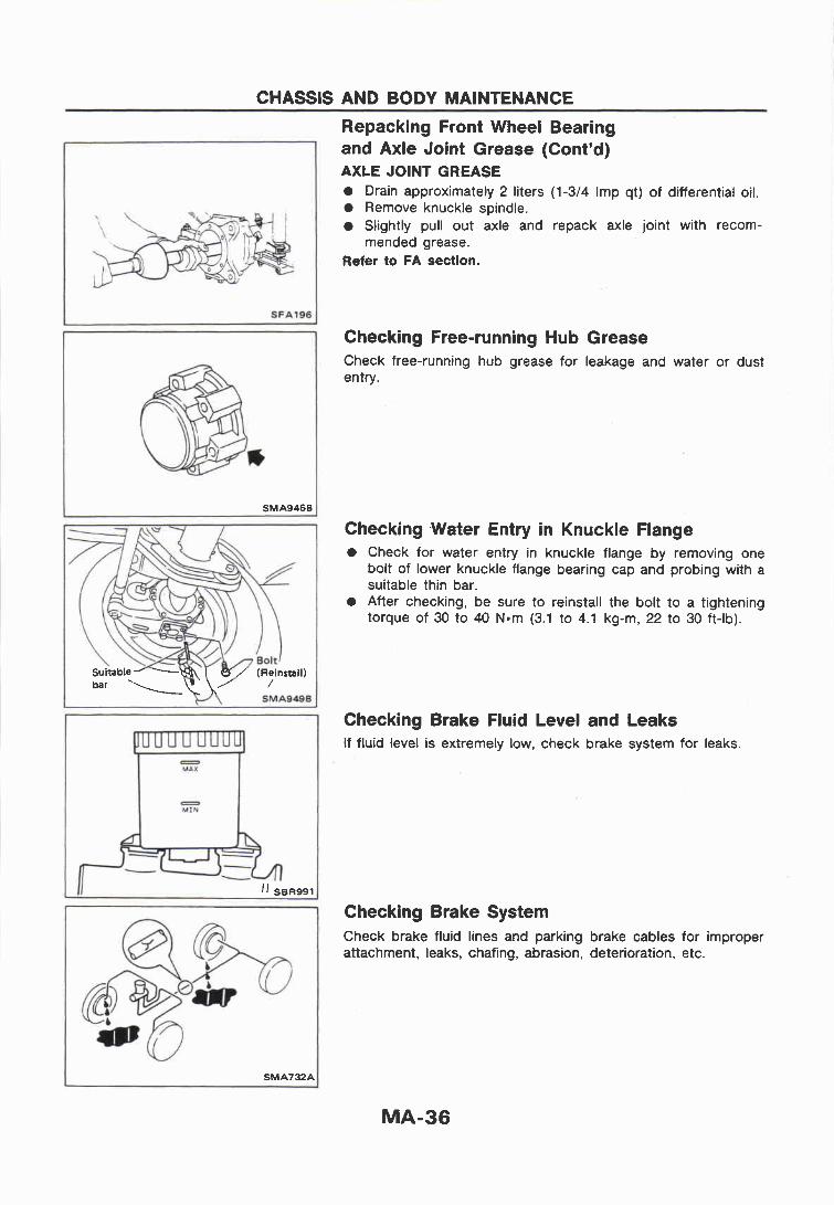
Repacking Front Wheel Bearing and Axle Joint Grease (Cont'd) AXLE JOINT GREASE a Drain approximately 2 liters (1-314 Imp qt) of differential oil. a Remove knuckle spindle.
Slightly pull out axle and repack axle joint with recorn- mended grease.
Refer to FA section.
Checking Free-running Hub Grease Check free-running hub grease for leakage and water or dust entry.
Checking -Water Entry in Knuckle Flange Check for water entry in knuckle flange by removing one bolt of lower knuckle flange bearing cap and probing with a suitable thin bar.
a After checking, be sure to reinstall the bolt to a tightening torque of 30 to 40 Nom (3.1 to 4.1 kg-rn, 22 to 30 ft-lb).
Checking Brake Fluid Level and Leaks If fluid level is extremely low, check brake system for leaks.
Checking Brake System Check brake fluid lines and parking brake cables for improper attachment, leaks, chafing, abrasion, deterioration, etc.
CHASSIS AND BODY MAINTENANCE
Changing Brake Fluid 1. Drain brake fluid from each air bleeder valve. 2. Refill until new brake fluid comes out from each air bleeder
valve. Use same procedure as in bleeding hydraulic system to refill brake fluid. Refer to section BR. Refill with recommended brake fluid "DOT 3". Never reuse drained brake fluid. Be careful not to splash brake fluid on painted areas.
Checking Brake Booster, Vacuum Hoses, Connections and Check Valve Check vacuum lines, connections and check valve for improper attachment, air tightness, chafing and deterioration.
Checking Disc Brake Check condition of disc brake components.
ROTOR Check condition and thickness.
Standard thickness: CL36VA
22.0 mm (0.866 in) ADPOVC
18.0 mm (0.709 in) Minimum thickness:
CL36VA 20.0 mm (0.787 in)
ADPOVC 16.0 mm (0.630 in)
CALIPER Check operation and leakage.
CHASSIS AND BODY MAINTENANCE
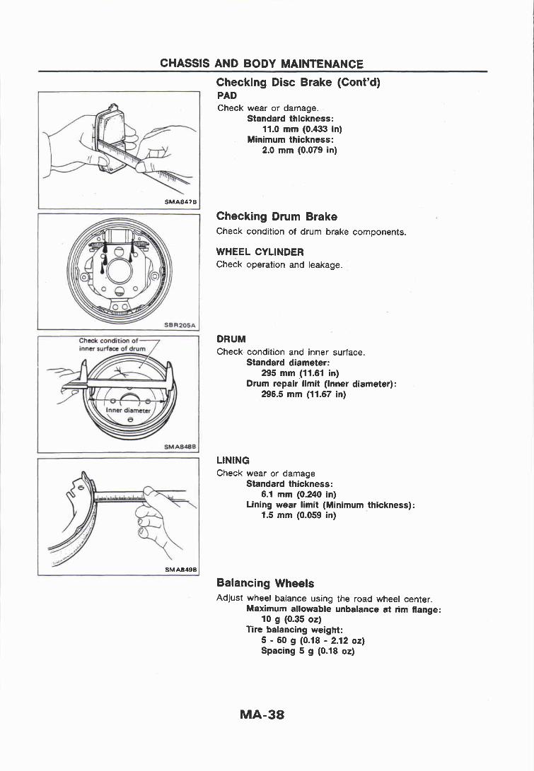
Checking Disc Brake (Cont'd) PAD Check wear or damage.
Standard thickness: 11.0 mm (0.433 in)
Minimum thickness: 2.0 mm (0.079 in)
Checking Drum Brake Check condition of drum brake components.
WHEEL CYLINDER Check operation and leakage.
DRUM Check condition and inner surface.
Standard diameter: 295 mm (11.61 in)
Drum repair limit (Inner diameter): 296.5 mm (11.67 in)
LINING Check wear or damage
Standard thickness: 6.1 mm (0.240 in)
Lining wear limit (Minimum thickness): 1.5 mm (0.059 in)
Balancing Wheels Adjust wheel balance using the road wheel center.
Maximum allowable unbalance at rim flange: 10 g (0.35 oz)
Tire balancing weight: 5 - 60 g (0.18 - 2.12 OZ) Spacing 5 g (0.18 oz)
The number of plies is the same on both front and rear tires.
Right front Right rear Spare
tim
Left front Left rear SMAIOOB
The number of plies differs between front and rear tires.
Right front Right rear Spare
Leh frw Left rear SMA9428
Filler plug opening
. .
(On ushide) MA&-8
CHASSIS AND BODY MAINTENANCE
Tire Rotation PJ1: Wheel nuts
118 - 147 N-m (12 - 15 kg-m, 87 - 108 ft-lb)
Checking Power Steering System Fluid and Lines
Check fluid level, when the fluid is cold.
Checking Steering Gear Oil Level and Leaks Check steering gear for oil level and leakage. Check oil level.
Oil level: Distance "A"
37 mm (1.46 in) or less Be careful not to overflow gear oil when filling up.
Check lines for improper attachment, leaks, cracks, damage, loose connections, chafing and deterioration.
CHASSIS AND BODY MAINTENANCE
Checking Steering Damper Check steering damper for damage and oil leakage.
Checking Steering Gear Box and Linkage STEERING GEAR
Check gear housing and boots for looseness, damage or grease leakage. Check connection with steering column for looseness.
STEERING LINKAGE Check ball joint, dust cover and other component parts for looseness, wear, damage or grease leakage.
Greasing Steering Linkage Apply multi-purpose grease to greasing points using suitable grease nipples.
CHASSIS AND BODY MAINTENANCE
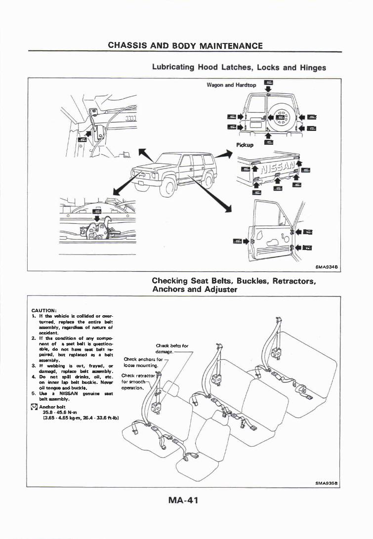
Lubricating Hood Latches, Locks and Hhges
Checking Seat Belts, Buckles, Retractors, Anchors and Adjuster
CAUTION: 1. If tb vehicle is cdlided or over-
turned. replace the entire bdt assembly. m r d k s of nature of accident.
2. If the condition of any corn* nent of a seat belt b question- Check belts for able. do not haw mat beit re- p a i d . but replaced ar a W t assembly.
3. If webbing is out, frayed, or loosemounti damagd, replace belt assambly.
4. Do not spill drinks, oil, etc. Check on inner lap belt buckle. Never for sm oil tongue and buckle.