+ All Categories
Home > Documents > MAC PROTOCOL ADAPTATION IN COGNITIVE RADIO NETWORKS

MAC PROTOCOL ADAPTATION IN COGNITIVE RADIO NETWORKS

Date post: 01-Feb-2022
Category:
Upload: others
View: 2 times
Download: 0 times
Share this document with a friend
42
MAC PROTOCOL ADAPTATION IN COGNITIVE RADIO NETWORKS by KUO-CHUN HUANG A thesis submitted to the Graduate School—New Brunswick Rutgers, The State University of New Jersey in partial fulfillment of the requirements for the degree of Master of Science Graduate Program in Electrical and Computer Engineering Written under the direction of Professor Dipankar Raychaudhuri and approved by New Brunswick, New Jersey October, 2010
Transcript

MAC PROTOCOL ADAPTATION IN COGNITIVERADIO NETWORKS

by

KUO-CHUN HUANG

A thesis submitted to the

Graduate School—New Brunswick

Rutgers, The State University of New Jersey

in partial fulfillment of the requirements

for the degree of

Master of Science

Graduate Program in Electrical and Computer Engineering

Written under the direction of

Professor Dipankar Raychaudhuri

and approved by

New Brunswick, New Jersey

October, 2010

ABSTRACT OF THE THESIS

MAC PROTOCOL ADAPTATION IN COGNITIVE

RADIO NETWORKS

By KUO-CHUN HUANG

Thesis Director:

Professor Dipankar Raychaudhuri

This thesis presents an adaptive MAC (AMAC) protocol for supporting MAC layer

adaptation in cognitive radio networks. MAC protocol adaptation is motivated by the

flexibility of emerging software-defined radios which make it feasible to dynamically

adjust radio protocols and parameters in order to maintain communications quality.

Dynamic changes to the MAC layer may be useful in tactical or vehicular networking

scenarios, where radio node density, traffic volumes and service requirements can vary

widely over time. A specific control framework for the proposed AMAC algorithm is

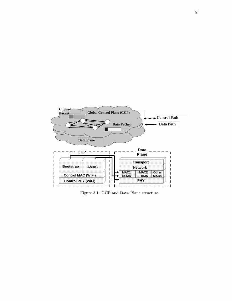
described based on the ”CogNet” protocol stack which uses a Global Control Plane

(GCP) to distribute control information between nearby radios. An AMAC prototype

which switches between CSMA and TDMA is evaluated for various traffic scenarios

using the NS-2 simulator. In addition, a proof-of-concept AMAC is implemented using

GNUradio/USRP platforms on the ORBIT radio grid testbed. Detailed simulation

and experimental results are given for both UDP and TCP traffic with different usage

scenarios and application models. The results show that AMAC can provide improved

performance relative to a conventional static system and can be implemented with

reasonable control protocol overhead and latency.

ii

Table of Contents

Abstract . . . . . . . . . . . . . . . . . . . . . . . . . . . . . . . . . . . . . . . . ii

List of Tables . . . . . . . . . . . . . . . . . . . . . . . . . . . . . . . . . . . . . iv

List of Figures . . . . . . . . . . . . . . . . . . . . . . . . . . . . . . . . . . . . v

1. Introduction . . . . . . . . . . . . . . . . . . . . . . . . . . . . . . . . . . . 1

2. Related Work . . . . . . . . . . . . . . . . . . . . . . . . . . . . . . . . . . . 5

3. Network Architecture . . . . . . . . . . . . . . . . . . . . . . . . . . . . . 7

4. AMAC Protocol . . . . . . . . . . . . . . . . . . . . . . . . . . . . . . . . . 9

5. SIMULATION RESULTS . . . . . . . . . . . . . . . . . . . . . . . . . . . 15

5.1. Scenario with Mixed Traffic Pattern . . . . . . . . . . . . . . . . . . . . 16

5.2. Scenario with Mobile Environment (network type) . . . . . . . . . . . . 18

5.3. Scenario with Mobile Environment (service requirement) . . . . . . . . . 20

6. EXPERIMENTAL EVALUATION ON GNU RADIO/ORBIT . . . 24

6.1. Experiment Setup . . . . . . . . . . . . . . . . . . . . . . . . . . . . . . 24

6.2. Experimental Results . . . . . . . . . . . . . . . . . . . . . . . . . . . . . 26

7. Conclusion . . . . . . . . . . . . . . . . . . . . . . . . . . . . . . . . . . . . 33

References . . . . . . . . . . . . . . . . . . . . . . . . . . . . . . . . . . . . . . . 34

Appendix A. Appendix . . . . . . . . . . . . . . . . . . . . . . . . . . . . . . 36

iii

List of Tables

4.1. GCP beacon message format . . . . . . . . . . . . . . . . . . . . . . . . 10

4.2. Control message format for MAC switching request . . . . . . . . . . . . 12

5.1. GENERAL SIMULATION PARAMETERS . . . . . . . . . . . . . . . . 15

6.1. GNURADIO(Data Plane) radio parameters . . . . . . . . . . . . . . . . 25

6.2. AMAC overhead from GCP control traffic . . . . . . . . . . . . . . . . . 32

iv

List of Figures

3.1. GCP and Data Plane structure . . . . . . . . . . . . . . . . . . . . . . . 8

4.1. Example network of AMAC protocol . . . . . . . . . . . . . . . . . . . . 14

5.1. Characteristics of CSMA and TDMA with streaming traffic . . . . . . . 17

5.2. Characteristics of CSMA and TDMA with bursty traffic . . . . . . . . . 18

5.3. Flow traffic type in mix traffic scenario . . . . . . . . . . . . . . . . . . . 19

5.4. Average throughput of mix traffic scenario . . . . . . . . . . . . . . . . . 20

5.5. Mobile scenario with different MAC-type networks . . . . . . . . . . . . 21

5.6. Average network throughput of city, mobile and suburban networks . . 22

5.7. Mobile scenario with mix service types . . . . . . . . . . . . . . . . . . . 22

5.8. Average network throughput of VoIP, streaming and web browsing net-

works . . . . . . . . . . . . . . . . . . . . . . . . . . . . . . . . . . . . . 23

6.1. Experimental network topology for AMAC . . . . . . . . . . . . . . . . 25

6.2. Average throughput of UDP traffic with larger packet size . . . . . . . . 27

6.3. Average throughput of UDP traffic with smaller packet size . . . . . . . 27

6.4. Average throughput of UDP traffic with smaller packet size . . . . . . . 28

6.5. Average throughput of CSMA, TDMA and AMAC over TCP transmission 29

6.6. Topology of multi-hop scenario . . . . . . . . . . . . . . . . . . . . . . . 30

6.7. Throughput comparison varied with time between CSMA, TDMA and

AMAC . . . . . . . . . . . . . . . . . . . . . . . . . . . . . . . . . . . . . 31

6.8. Average throughput of CSMA, TDMA and AMAC . . . . . . . . . . . . 31

A.1. NS-2 programming flow chart . . . . . . . . . . . . . . . . . . . . . . . . 36

A.2. GNUradio programming stacks . . . . . . . . . . . . . . . . . . . . . . . 37

v

1

Chapter 1

Introduction

The concept of cognitive radio (CR) [1] is to dynamically choose a wide variety of radio

parameters and network protocol standards in order to adapt to observed radio link

and network conditions. Such a cognitive radio system is capable of handling cross-

layer parameter changes: at the physical layer, the agile radio can search so-called

spectrum white space from unlicensed and even licensed bands to make good use of

the spectrum opportunities with power control and modulation waveform adaptation;

at the network layer, the cognitive radio system can also make runtime changes to the

protocols used for packet transmission, to avoid collisions and congestion when network

topology or traffic characteristics change. The ability to adapt different protocol layers

with cognitive radio technology offers the prospect of improved networking performance

in dynamic wireless networking scenarios such as tactical and vehicular.

There have been many research works addressing the physical layer agility of a

cognitive radio system based on dynamic spectrum access (DSA) technique [2] [3].

However, there still is lack of a systematic study of how the cognitive radio performs

with medium access control (MAC) protocol adaptation. This thesis proposes a novel

adaptive MAC (AMAC) design for cognitive radio networks, with the ability to adapt

between different types of MAC protocols based on the observation of network traffic

changes. The candidate medium access protocols usually have different advantages in

various network situations, and the AMAC protocol provides a framework to observe the

runtime network changes and makes judgments for switching between those candidate

protocols on the fly.

2

The proposed AMAC protocol is based on the CogNet cognitive radio protocol archi-

tecture described in [4]. The CogNet architecture includes the concept of a ”global con-

trol plane (GCP)” which supports exchange of control information between networking

cognitive radio devices. MAC adaptation under consideration here requires exchange of

local cross-layer parameters and tokens to maintain the protocol consistency between

radio nodes sharing the same physical channel. The same GCP framework has been

used in earlier work for dynamic spectrum coordination in multi-radio environments

[5], as well as for cross-layer ad hoc network routing [4].

In this thesis, we focus on how to switch between different MAC protocols. Since

the MAC protocols have different edges in different network scenarios, we propose

three strategies for local nodes to determine what is the right time to initiate a switch.

However, if different MAC protocols are used in the local network, different packet

transmission schedules may cause more collisions than single MAC in the network’s

point of view. Thus, we choose a simple approach to derive the common MAC protocol

for the smaller network. Additionally, in order to maintain MAC protocol consistency

in the larger network, we introduce another approach of cross-layer design to reach

common MAC protocol for the end-to-end link.

The candidate medium access control protocols we have chosen for evaluation rep-

resent the two most commonly used classes of wireless network protocols: CSMA and

TDMA. CSMA is easy to implement and is efficient for supporting short packet trans-

missions from bursty sources with light to medium traffic volumes. In heavier traffic

scenario, particularly with streaming sources, it is well known that TDMA provides

a more efficient and reliable solution. In mobile environment, when the mobiles in

data transmission are driving from city to suburban area, they can adapt MAC proto-

col from TDMA-based MAC to CSMA-based MAC. TDMA is able to reduce collision

under dense network such as city area and CSMA provides flexibility under scattered

network such as suburban area. A cell phone user, for instance, can use TDMA-based

MAC for GSM system (voice transmission) and CSMA-based MAC for WiFi system

(data transmission). Other MAC protocols can also be used in conjunction with AMAC,

even though our GNU radio implementation is currently limited to CSMA and TDMA.

3

We present the simulation and implementation aspects of AMAC protocol. NS-

2 simulator is used to emulate the behavior of AMAC in varying environments and

network types. GNU radio on the ORBIT radio grid testbed [6] is the platform we use

to validate AMAC’s practicality. GNU radio is a type of software defined radio (SDR),

which provides considerable flexibility for runtime adaptation of both physical layer

signal parameters as well as MAC protocol functions. It integrates simple hardware and

high functional software to construct simple radios which support intelligent control in

cognitive radio network. There are two main components in GNUradio: host processor

and USRP. USRP is a software radio transceiver that converts between digital and

analog signals. It is able to support multiple radio band such as ISM band or 400MHz

band. The host is a general-purpose computer that processes the baseband digitized

raw signals and connects to USRP through USB cable. The Python/C++ based PHY

modules are built in the GNUradio library and we can program under python interface

to control PHY or radio parameters on-the-fly. However, due to the unpredictable

processing delay in the host and high communication latency through USB, the MAC

operations required timely responses are not supported yet. In this implementation, we

build our own coarse TDMA MAC and basic CSMA MAC modules to validate GCP

architecture and AMAC algorithm are implementable in the real world.

We evaluate the proposed AMAC protocol with various traffic types and environ-

ments. The purpose of the study is to validate the control protocol by which AMAC

coordinates MAC protocol switching in different applications and measure the con-

trol overhead. In simulation, we compare CSMA and TDMA in bursty and streaming

traffic scenarios and validate AMAC significantly improves throughput performance in

dynamic traffic scenarios. In mobile network, we show the average throughput of mo-

bile nodes transmission is improved by adapting different MAC protocols in different

node density environments. For different service type networks, AMAC is shown to

maintain service requirement and provides fairness for the neighbor networks. In im-

plementation, we first present AMAC performance with baseline static TCP and UDP

traffic and environment. Additionally, system performance in terms of throughput with

varying UDP packet size is studied in the multihop scenario. These proof-of-concept

4

GNU radio experiments within the ORBIT radio grid testbed at Rutgers University

[6] are intended to demonstrate the feasibility of building an adaptive wireless network

using the CogNet GCP architecture.

In the next chapter, we begin by describing related work. That is followed by our

network architecture in chapter 3, the structure that we used for AMAC protocol.

Then chapter 4 provides a detailed discussion of the proposed AMAC protocol and the

associated adaptation algorithms. In chapter 5, several NS-2 simulation scenarios and

performance results are presented. We provide experimental GNUradio prototyping

results to further validate AMAC performance in chapter 6 and the conclusion is in

chapter 7.

5

Chapter 2

Related Work

The benefits of separate control and data planes in the CogNet architecture have been

previously explained in [4]. In [7], the Ad hoc network also uses separate control channel

to transmit RTS/CTS control packets and selects the best data channel with highest

SINR (signal-to-interference and noise ratio). The free data channel list is embedded

in the RTS/CTS packet to find the best matching data channel. Our global control

plane (GCP) uses a low-rate radio PHY with wide coverage for robustness, and has

more functions which include protocol modules for topology discovery, bootstrapping,

and address assignment. The data plane protocol stack supports data communication

via PHY, MAC and routing modules specified through an API that interacts with the

control modules in the radio node. This GCP control architecture can be used for

various design objectives ranging from spectrum etiquette [8], adaptive MAC under

consideration here, as well as cross-layer path setup and routing [4]. With the concept

of fixed and separate control channel, this GCP architecture can maximize the use of

spectrum without knowing the signal parameters in advance.

In [9], the author uses the rendezvous channel (RC) to coordinate among wireless

nodes in different channels. C-MAC operates over decentralized multi-channels CR

networks with dynamic RC. Also, each data superframe has to sacrifice its beacon

period to get control information which causes overhead to affect data transmitting. In

[10] existing MAC protocols are combined into a single higher layer, using only local

network feedback information to determine the optimum MAC protocol. However, this

work does not consider the global network view for switching different MACs and takes

an amount of time to determine the optimum MAC after comparing the performance

of all candidate MACs.

6

In [11], a TDMA implementation for software defined radios is proposed. Different

software frameworks for TDMA are used for implementation: GNU radio for PHY

layer development and Click for protocol development. However, the time slot for this

TDMA design is around 1 second, too large a value to be useful for most applications.

Ref [12] modifies the functions required for faster processing by the CRs FPGA instead

of the host CPU, providing for better timing in a MAC layer implementation. Ref [13]

also uses GNU radios for PHY implementation and Click for MAC development and

reports preliminary experiments in the Hydra system. Ref [14] proposes the hardware

platform, KUAR, to develop the cognitive radio and also incorporate the SDR platforms

to control the parameters.

7

Chapter 3

Network Architecture

The proposed GCP-based cognitive radio network architecture is shown in Figure 3.1.

A global control plane is used to carry all the control information exchanged between

nodes while the data plane is dedicated for data transmission. The concept of GCP

can be implemented using various methods such as a separate control radio or a control

mode the agile radio can periodically switch to. In this thesis, we utilize an additional

low-cost control radio operating on a dedicated control channel which is in charge of

the resource reservation and allocation of radio and protocol parameters. The control

radio is designed to have greater range and lower data rate as compared to the radio

in data plane. The GCP offers basic control functions such as the initial bootstrapping

as well as topology discovery when the new nodes join the network, and subsequently

supports adaptive MAC operation when network or environment condition changes.

Radio parameters could be optimized for end-to-end data transmission in different

scenarios with different traffic situations.

The data plane protocol stack on each node, linked with the GCP through APIs,

handles service data between the wireless nodes, while the GCP assists in establishing

the operating PHY, MAC and routing parameters. Data is transmitted in the estab-

lished data path negotiated using the GCP protocols. The actual data plane media

access control protocols can be dynamically switched between candidate protocols in

response to observed changes in network condition and/or service requirements. The

AMAC algorithm is implemented in the control plane and candidate MAC protocols

are implemented in the data plane.

8

Global Control Plane (GCP)

Data Plane

Control Packet

Data Packet

Control Path

Data Path

MAC1 CSMA

Network

Transport

PHYControl MAC (WiFi)

Bootstrap

Control PHY (WiFi)

MAC2 TDMA

AMAC

OtherMACs

GCP Data Plane

Figure 3.1: GCP and Data Plane structure

9

Chapter 4

AMAC Protocol

The flexibility offered by cognitive radios makes it possible to design adaptive wireless

networks that adjust the protocol stack used based on observed external conditions or

service requirements. For example, in a vehicular scenario, there can be large variations

in radio node density as cars move from an urban intersection to a highway. CSMA/CA

protocol might work well in certain situations when the number of nodes is small,

but it may be beneficial to switch to alternative protocols such as TDMA to avoid

instability and hidden-node problems when the number of neighbor nodes increases

dramatically. Additionally a separate control protocol can assist with seamless roaming

across networks supporting different network conditions. Thus, we develop a protocol

framework for dynamic adaptation of MAC layer protocols, considering the examples

of switching between CSMA/CA and TDMA.

(1). AMAC architecture

This ”Adaptive MAC Protocol (AMAC)” mainly focuses on switching among dif-

ferent MAC protocols to achieve better overall network performance. The proposed

AMAC protocol is able to incorporate channel coordination when available vacant chan-

nel is detected and to adjust MAC/PHY configurations according to different service

requirements and network node density. The GCP outlined earlier provides a control

framework to set up network adaptation functions.

It is important for cognitive radio nodes to start with bootstrapping and discovery

process in this GCP-based framework. The bootstrapping function can help configure

PHY/MAC capabilities and current status when the nodes power up. After initializa-

tion, a discovery protocol is executed to provide end-to-end reachability and determine

optimum path information across multiple hops. Based on these exchanged control

10

messages, nodes are able to initiate data transmission.

The proposed AMAC protocol is used to apply different operating conditions in

which wireless nodes can achieve efficient data communication. It dynamically changes

MAC behavior on-the-fly and configures per-hop PHY parameters of the data plane at

each intermediate node. AMAC includes three phases as following:

• Baseline MAC selection: Each node starts with the MAC protocol which handles

the nominal light network traffic condition (CSMA is used in this paper).

• PHY adaption: Nodes first try to discover if they can adapt PHY parameters

(such as operating channel, power or modulation type) when the performance of

data transmission drops significantly.

• MAC adaptation: When the PHY adaptation is not able to meet performance

goals, nodes may initiate a switch of the MAC protocol. AMAC provides a

mechanism to let each node negotiate with others and find the suitable MAC

protocol commonly used for different network environments.

When the cognitive radio node powers on, it first listens and collects control beacon

messages from nearby nodes by using GCP. If the node decides to join the network, it

starts by flooding control messages in the GCP to form the initial network connections.

Beacon message includes required information of nodes states and ID. In Table 4.1, we

show the format of periodic beacon messages (operating MAC, frequency and power)

which update neighboring radios with a nodes latest parameters.

Type Flags Sender ID

Beacon Transmit Power Max PHY Rate

Operating Frequency Operating MAC

Table 4.1: GCP beacon message format

The key requirement in choosing a baseline operating MAC is to ensure flexible date

communication. For instance, CSMA-based MAC is simple, flexible and able to handle

most networks with low traffic load; TDMA-based MAC has a fixed structure and avoid

11

repeated channel contentions for scenarios with stream traffic. As a result, we choose

CSMA as the baseline MAC and consider switching to TDMA when performance is

degraded due to excessive contention.

Node mobility in vehicular environments can result in major changes to the prop-

agation environment, radio density and network topology. Cognitive radio nodes are

capable of adjusting PHY parameters (e.g. frequency, power, rate, modulation) on the

fly when the performance degrades. Each transmitting node will monitor performance

(i.e. throughput or delay) of data transmission periodically. When the performance

requirement goes below specified objectives, the nodes will initiate PHY parameters

adaptation via the GCP to negotiate suitable configurations, such as switching to empty

channels or power adjustment.

When PHY adaptation alone fails to meet performance objectives, the next level of

adaptation involves change of the MAC protocol. AMAC grants cognitive radio nodes

a further way to solve degraded performance caused by contention. When there are

nodes initiating video streaming in a high network density area, it may be hard to

satisfy the required QoS with PHY adjustments. Instead, if the nodes can adjust the

MAC protocol with time or frequency schedule management (i.e. TDMA or FDMA),

the desired QoS can potentially be achieved. As another example, a mobile cognitive

radio moving from a sparse rural area to an urban can switch between two MAC layer

protocols (such as CSMA and TDMA) to deal with such major changes in operating

environment.

However, if all the cognitive radio nodes change their MAC protocol based on a local

decision, the protocols used by all nodes may not be compatible. Thus, we introduce a

voting scheme for nodes to agree on the MAC protocol to be used across the whole net-

work. While a sender requests MAC switching based on previously outlined algorithms,

it first broadcasts in the GCP about which MAC protocol it would like to apply. The

nodes receiving this ”MAC switch request” message will respond with a GCP message

indicating their local decisions. In this way, nodes vote for the MAC protocol to be

used and the common protocol for the network is determined by the majority nodes.

The control message format for the voting scheme is shown in Table 4.2.

12

Type Flags Sender ID

MAC Type

Table 4.2: Control message format for MAC switching request

Indeed, the above approach can assist with deciding common MAC protocol in

smaller network. For the larger network, we believe the voting scheme requires excessive

amount of time to collect the local decisions and is not suitable to force quiet amount

of nodes to change to other MAC protocols. Therefore, we present a cross-layer design

strategy to let end-to-end link use the same MAC protocol without forcing other links to

use the same MAC protocol in the same network. The basic concept of this approach is

we combine channel assignment with MAC protocol, which means the pre-defined sub-

channels are only dedicated to some pre-assigned MAC protocols. In the case of CSMA

and TDMA MAC, we assign one channel dedicated to TDMA MAC and the others

for CSMA MAC. According to the above scheme, if the nodes transmitting data with

CSMA MAC request to switch, they will first to switch other CSMA MAC channels.

Unless the CSMA MAC channels are not able to satisfy the nodes’ requirement, then

they will switch to TDMA dedicated channel to maintain the performance. Thus, each

node does not require to reach the common MAC and this scheme will not over load

the control channel either.

(2). MAC Switching Schemes for AMAC

Here, we propose three strategies to help cognitive-radio nodes decide whether to

request MAC switching.

• performance degradation threshold

• predicted future traffic patterns

• network density

In the first approach, each node computes its performance in an observation interval

while data traffic flows continue. If performance is degraded below some threshold, the

node will request a MAC switch. In this approach, we focus on maintaining the node’s

13

performance in order to satisfy application requirements such as throughput or delay. In

the second approach, each node checks its future traffic patterns by periodically exam-

ining the MAC transmit buffer. If the average packet size is large, the node may request

a TDMA MAC switch in order to reduce contention. On the other hand, for smaller

average packet size light load, CSMA is preferable to prevent unnecessary wastage of

slot time. Besides, AMAC is able to provide better performance under conditions of

different traffic types. Bursty traffic, for instance, can be transmitted efficiently with

CSMA; however, streaming traffic is better suited for TDMA transmission because of

improved reliability and lower contention.

In the third approach, GCP enables each node to detect the network density and

topology in a mobile environment. With AMAC, each mobile node can adapt suitable

MAC to different networks or requirements on the fly without degrading the perfor-

mance of neighbor networks. Using a single MAC everywhere may cause lots of con-

tention or inefficiency in certain mobility scenarios such as vehicles moving from dense

city areas to sparse suburban environments.

An example network of data traffic starting from the sender to the receiver with

AMAC MAC capability handling both CSMA and TDMA modes is shown in Figure

4.1. During the bootstrap process, all the nodes are able to obtain a global view of

the network by exchanging beacons. After data traffic is initiated, the sender node

uses CSMA as its baseline MAC protocol. In the mean time, the sender computes

the average throughput of its packets periodically (e.g., an average of ten packets).

When the performance in the observation interval drops more than 20% compared to

the previous observation interval, the node will initiate a request to switch to TDMA

using the GCP. When all its neighbor nodes receive the request, they vote on whether

to switch to the proposed MAC protocol based on their local throughput performance.

As shown in Figure 4.1, node A, C and Receiver all agree to switch to TDMA and node

B votes to keep using CSMA. In the end, the TDMA MAC will be switched on for all

the nodes based on the majoritys voting decision.

14

Control link

Data pathA

C

TDMATDMA

Sender

Receiver

CSMA

Throughput drop > 20%Request TDMA Switch

BTDMA

Figure 4.1: Example network of AMAC protocol

15

Chapter 5

SIMULATION RESULTS

In this chapter, we present the simulation results for the AMAC algorithm using the

GCP framework. We use the NS-2 simulator to evaluate the above design for represen-

tative usage scenarios. Note that the default NS-2 model is modified to two interfaces -

control and data interface. The control MAC is set up as 802.11 CSMA and data MAC

as AMAC in comparison with CSMA and TDMA. Based on the above configuration

and parameters in Table 5.1, CBR/UDP and FTP/TCP traffic are generated at the

data interface to evaluate the performance of AMAC. In AMAC, we implemented two

candidate MACs - CSMA/CA and dynamic TDMA. The CSMA/CA MAC is similar

to the 802.11 MAC but without RTS/CTS reservations. For dynamic TDMA, the first

slot of a frame is used for synchronization and to check how many nodes have packets

to transmit. Therefore, the slot number of each frame can be adjusted to match the

number of transmitting nodes without wasted channel time.

Topology size 1000m x 1000m

Data Channel rate 11Mbps

Control Channel rate 1Mbps

PHY rate 2Mbps

Carrier Sensing Interval 20ms

Propagation Model TwoRayGround

Data Packet Size 1000Bytes

Path loss index 4

Table 5.1: GENERAL SIMULATION PARAMETERS

For the performance evaluation, we consider the following scenarios:

1. Mixed Traffic Pattern: Each node is fixed at a randomly-deployed location in

a 20m by 20m area. We generate the CBR/UDP traffic flows between any two

16

nodes and each flow generates two different traffic patterns - bursty and streaming

traffic.

2. Mobile Environment (type A): In this scenario, a group of mobile nodes move from

a low-density suburban area to a high-density urban area. Mixed CBR/UDP and

FTP/TCP traffic are generated by the mobile nodes while FTP/TCP traffic is

generated by the city and suburban nodes. In order to evaluate the MAC switch-

ing strategies, we consider only one available channel without PHY adaptation in

the first two scenarios.

3. Mobile Environment (type B): In this more complex mobile service scenario, we

implement two available channels in this network and one is dedicated for TDMA

MAC. Three groups of mobile nodes drive with each other and a group of static

nodes are nearby. VoIP, streaming data and web browsing service are generated

by the nodes, and the delay requirement of VoIP has to be satisfied.

5.1 Scenario with Mixed Traffic Pattern

Before this experiment, let’s first explore the characteristics of CSMA and TDMA

MAC to see which MAC protocol is preferable to what environment. We conduct

two experiments to evaluate TDMA and CSMA MAC characteristics. One experiment

is to generate CBR/UDP streaming traffic with an offered load 2Mbps for each flow

and the number of flows is increased. The other experiment is to simulate bursty

traffic by providing each flow a 10Mbps CBR/UDP load for 1 second and then 100kbps

CBR/UDP load for the rest of time. We increase the number of flows and each flow

takes turn to transmit bursty data which means the bursty 10Mbps load won’t be

overlapped in this network.

According to the Figure 5.1, for lighter traffic loads, TDMA and CSMA have similar

throughput. However, the more the flows generated, the higher throughput TDMA

MAC has compared to CSMA MAC (yields more than twice throughput with 100 flows

in the network). That is because the increase of the flows causes contention increase

and then drops CSMA MAC performance. For bursty traffic scenario, we generate

17

6

8

10

12

Throughput(Mbps)

TDMA

0

2

4

6

1 2 3 4 5 6 7 8 9 10 12 14 16 18 20 30 50 100

Throughput(Mbps)

TDMA

CSMA

Figure 5.1: Characteristics of CSMA and TDMA with streaming traffic

10Mbps CBR load for one second and the rest is 100kbps CBR/UDP load for each

flow. In the network point of view, each flow takes turn to transmit this one second

10Mbps load which means there won’t be overlapped 10Mbps load in any second of

data transmission. In Figure 5.2, the CSMA MAC outperforms TDMA MAC since the

bursty traffic flow with CSMA MAC is able to keep transmitting packets out while the

other flows are in low traffic. With TDMA MAC, each flow has to wait till its own

slot time and then transmit packet so it is unable to handle bursty traffic in time and

instead drop them. Based on the above result, this simulation runs with 40 nodes and

generates each flow as mixed CBR/UDP traffic (bursty and streaming traffic) which is

shown in Figure 5.3.

In Figure 5.4, we evaluate 8, 10 and 12 flows in this network. It can be noticed

from previous results that the more flows in streaming traffic, the bigger throughput

difference between TDMA and CSMA. However, for bursty traffic scenario, if the flow

number keeps increasing, the packet collision will be increasing, which cause CSMA

performance drops and the throughput difference is getting less. In order to reach

better AMAC performance gain, we choose 8 to 12 flows heavy traffic load in this

scenario. Since each flow combines different traffic types, the total average network

18

4

5

6

7

8

Av

era

ge

Th

rou

gh

pu

t(M

bp

s)

TDMA

0

1

2

3

4

1 2 3 4 5 6 7 8 9 10 12 14 16 18 20

Av

era

ge

Th

rou

gh

pu

t(M

bp

s)

Flow number

TDMA

CSMA

Figure 5.2: Characteristics of CSMA and TDMA with bursty traffic

load is controlled to be around 20Mbps in each case so as to avoid overloading the

channel. It can be noted that the average throughput of CSMA is a little better

than TDMA because CSMA is able to transmit more packets for bursty traffic even

though TDMA performs better in streaming traffic. The AMAC algorithm detects

the ”packets incoming rate” in the MAC buffer as switching threshold. If the rate is

high, the node will request TDMA as baseline MAC; In other cases, CSMA will be

selected. During bursty traffic transmission, because of non-overlapped bursty load in

the network, CSMA will tend to be selected by majority vote. TDMA will be chosen as

the common MAC while many nodes initiate 2Mbps streaming load. The result shows

the average throughput improves 20% compared to static TDMA and 15% compared

to static CSMA. This is because AMAC adapts to choose the best MAC for different

traffic types.

5.2 Scenario with Mobile Environment (type A)

In a vehicular scenario, there can be large variations in radio node density as mobile

nodes move from an urban intersection to a suburban highway. CSMA/CA might work

well in certain situations when the number of nodes is small, but it may be beneficial

19

Flow Traffic

8

10

12

Th

rou

gh

pu

t(M

bp

s)

0

2

4

6

8

1 2 3 4 5 6 7 8 9 101112131415161718192021222324252627

Th

rou

gh

pu

t(M

bp

s)

Time

UDP Load

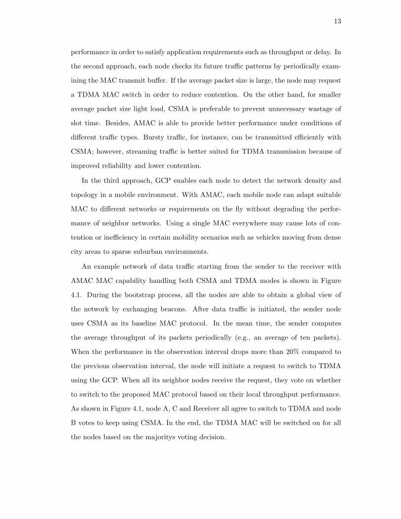
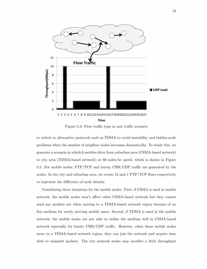
Figure 5.3: Flow traffic type in mix traffic scenario

to switch to alternative protocols such as TDMA to avoid instability and hidden-node

problems when the number of neighbor nodes increases dramatically. To study this, we

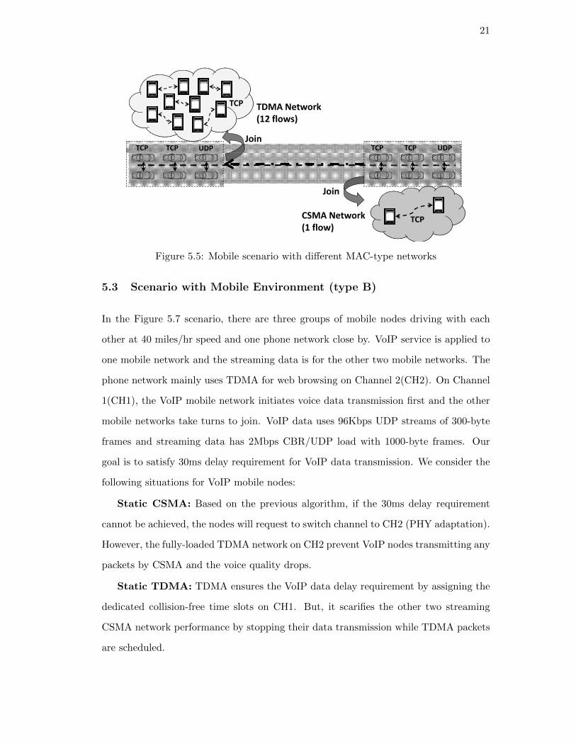
generate a scenario in which 6 mobiles drive from suburban area (CSMA-based network)

to city area (TDMA-based network) at 60 miles/hr speed, which is shown in Figure

5.5. For mobile nodes, FTP/TCP and bursty CBR/UDP traffic are generated by the

nodes. In the city and suburban area, we create 12 and 1 FTP/TCP flows respectively

to represent the difference of node density.

Considering three situations for the mobile nodes. First, if CSMA is used in mobile

network, the mobile nodes won’t affect other CSMA-based network but they cannot

send any packets out when moving to a TDMA-based network region because of no

free medium for newly arriving mobile users. Second, if TDMA is used in the mobile

network, the mobile nodes are not able to utilize the medium well in CSMA-based

network especially for bursty CBR/UDP traffic. However, when these mobile nodes

move to a TDMA-based network region, they can join the network and acquire time

slots to transmit packets. The city network nodes may sacrifice a little throughput

20

5

6

7

8

9

10

Throughout(Mbps)

8 Flows

10 Flows

0

1

2

3

4

CSMA TDMA AMAC

Throughout(Mbps)

10 Flows

12 Flows

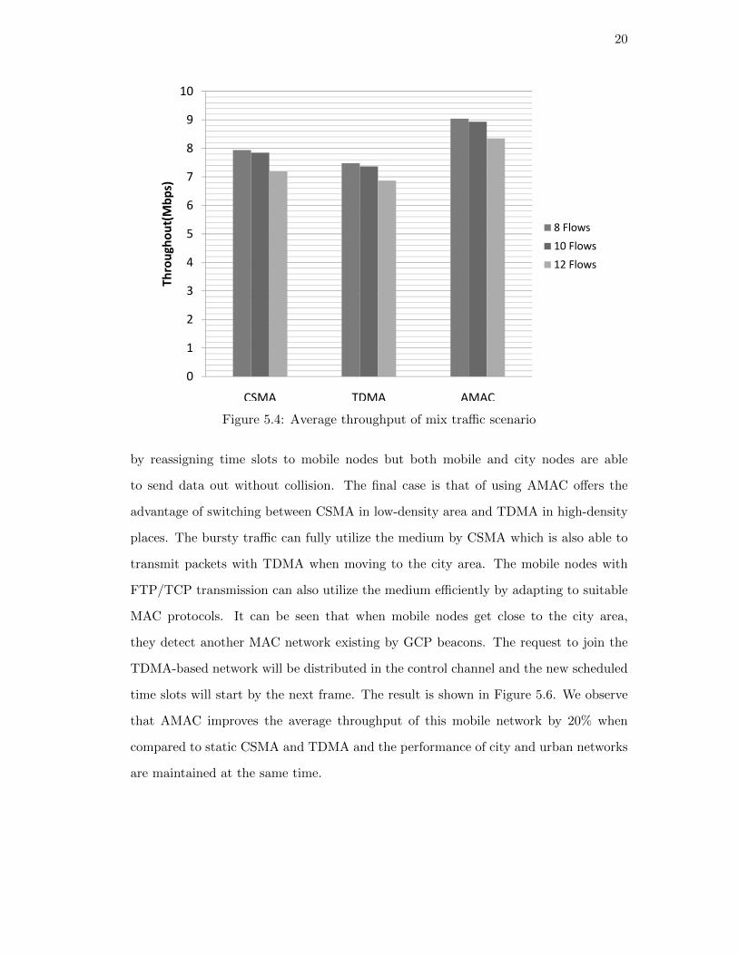
Figure 5.4: Average throughput of mix traffic scenario

by reassigning time slots to mobile nodes but both mobile and city nodes are able

to send data out without collision. The final case is that of using AMAC offers the

advantage of switching between CSMA in low-density area and TDMA in high-density

places. The bursty traffic can fully utilize the medium by CSMA which is also able to

transmit packets with TDMA when moving to the city area. The mobile nodes with

FTP/TCP transmission can also utilize the medium efficiently by adapting to suitable

MAC protocols. It can be seen that when mobile nodes get close to the city area,

they detect another MAC network existing by GCP beacons. The request to join the

TDMA-based network will be distributed in the control channel and the new scheduled

time slots will start by the next frame. The result is shown in Figure 5.6. We observe

that AMAC improves the average throughput of this mobile network by 20% when

compared to static CSMA and TDMA and the performance of city and urban networks

are maintained at the same time.

21

TCP TCP UDP

TDMA Network

(12 flows)

TCP

TCP TCP UDP

Join

CSMA Network

(1 flow)TCP

Join

Figure 5.5: Mobile scenario with different MAC-type networks

5.3 Scenario with Mobile Environment (type B)

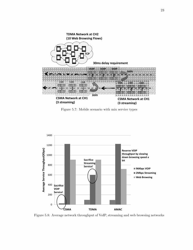
In the Figure 5.7 scenario, there are three groups of mobile nodes driving with each

other at 40 miles/hr speed and one phone network close by. VoIP service is applied to

one mobile network and the streaming data is for the other two mobile networks. The

phone network mainly uses TDMA for web browsing on Channel 2(CH2). On Channel

1(CH1), the VoIP mobile network initiates voice data transmission first and the other

mobile networks take turns to join. VoIP data uses 96Kbps UDP streams of 300-byte

frames and streaming data has 2Mbps CBR/UDP load with 1000-byte frames. Our

goal is to satisfy 30ms delay requirement for VoIP data transmission. We consider the

following situations for VoIP mobile nodes:

Static CSMA: Based on the previous algorithm, if the 30ms delay requirement

cannot be achieved, the nodes will request to switch channel to CH2 (PHY adaptation).

However, the fully-loaded TDMA network on CH2 prevent VoIP nodes transmitting any

packets by CSMA and the voice quality drops.

Static TDMA: TDMA ensures the VoIP data delay requirement by assigning the

dedicated collision-free time slots on CH1. But, it scarifies the other two streaming

CSMA network performance by stopping their data transmission while TDMA packets

are scheduled.

22

3

4

5

6

Av

era

ge

Ne

two

rk T

hro

ug

hp

ut(

Mb

ps)

City

Mobile

0

1

2

3

CSMA TDMA AMAC

Av

era

ge

Ne

two

rk T

hro

ug

hp

ut(

Mb

ps)

Mobile

Urban

Figure 5.6: Average network throughput of city, mobile and suburban networks

AMAC: While AMAC is applied for VoIP data transmission, it first uses CSMA

on CH1. After VoIP mobile nodes detect average delay is more than 30ms, switching to

TDMA in CH2 will be requested. The time slots in phone network will be reassigned

and the delay requirement is able to be satisfied.

In Figure 5.8, we can see that VoIP data transmission using AMAC reaches four

times throughput of static CSMA and the 2Mbps streaming data transmission can

achieve twice the throughput of TDMA. Although the throughput of TCP flows may

have dropped a little, it may be acceptable to trade off best effort web or content

applications against real-time voice or streaming video.

23

VOIP VOIP VOIP

TDMA Network at CH2

(10 Web Browsing Flows)

TCP

Join

30ms delay requirement

CSMA Network at CH1

(3 streaming)

CBR CBR CBRCBR CBR CBR

CSMA Network at CH1

(3 streaming)

Join

Join

Figure 5.7: Mobile scenario with mix service types

800

1000

1200

1400

Av

era

ge

Se

rvic

e T

hro

ug

hp

ut(

Kb

ps)

96Kbps VOIP

2Mbps Streaming

Sacrifice

Streaming

Service!

Reserve VOIP

throughput by slowing

down browsing speed a

bit

0

200

400

600

CSMA TDMA AMAC

Av

era

ge

Se

rvic

e T

hro

ug

hp

ut(

Kb

ps)

2Mbps Streaming

Web Browsing

Sacrifice

VOIP

Service!

Figure 5.8: Average network throughput of VoIP, streaming and web browsing networks

24

Chapter 6

EXPERIMENTAL EVALUATION ON GNU

RADIO/ORBIT

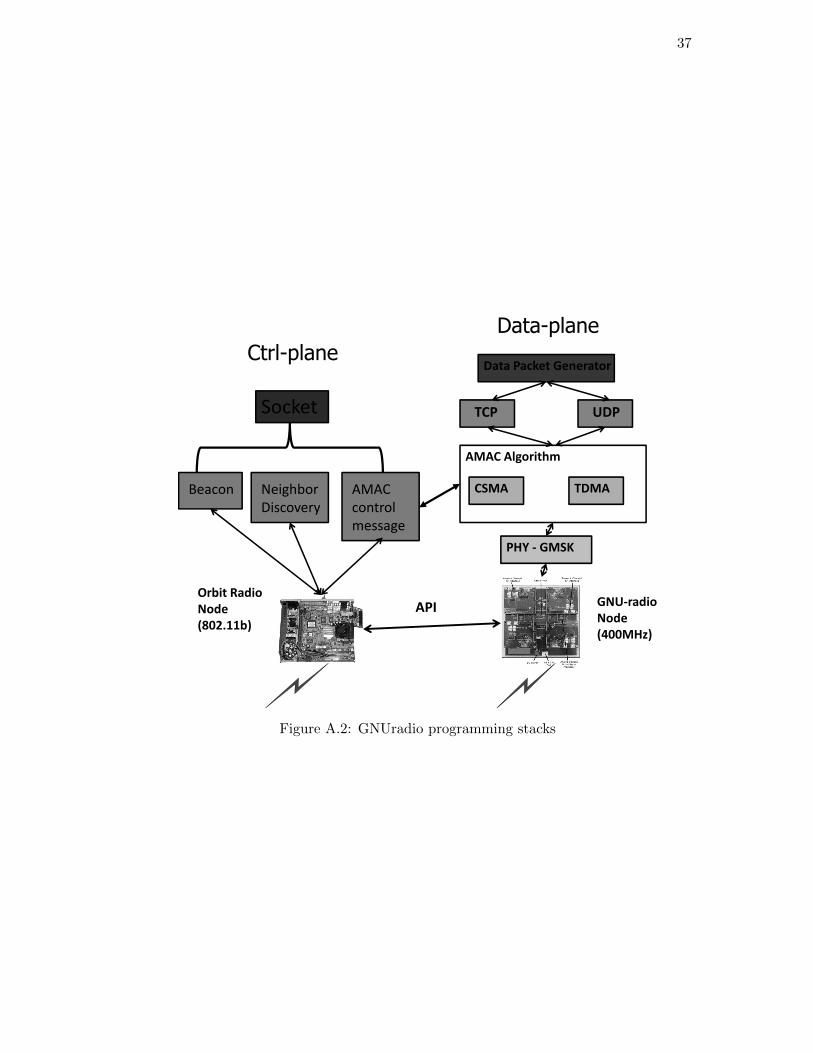
In this chapter, we present results from experimental prototyping of the proposed

AMAC protocol using the GNU/USRP software radio platform available on the OR-

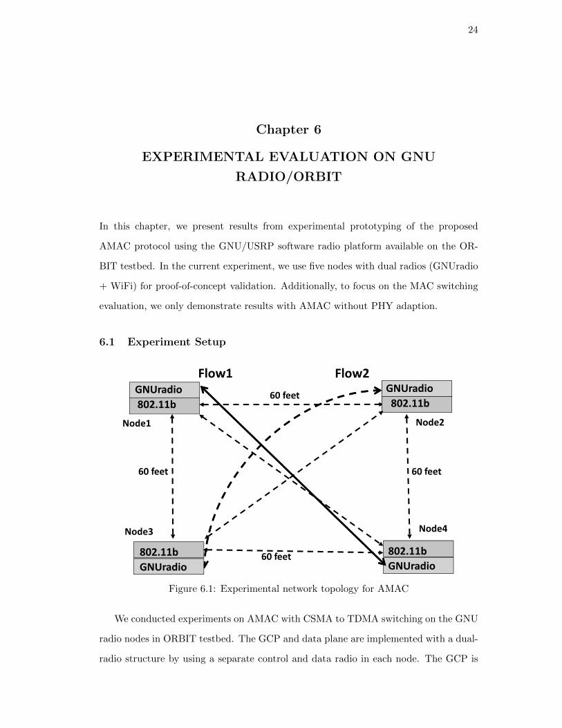
BIT testbed. In the current experiment, we use five nodes with dual radios (GNUradio

+ WiFi) for proof-of-concept validation. Additionally, to focus on the MAC switching

evaluation, we only demonstrate results with AMAC without PHY adaption.

6.1 Experiment Setup

GNUradio

802.11b

Node1 Node2

GNUradio

802.11b60 feet

Flow1 Flow2

Node3

GNUradio

802.11b

GNUradio

802.11b

60 feet

60 feet

60 feet

Node4

Figure 6.1: Experimental network topology for AMAC

We conducted experiments on AMAC with CSMA to TDMA switching on the GNU

radio nodes in ORBIT testbed. The GCP and data plane are implemented with a dual-

radio structure by using a separate control and data radio in each node. The GCP is

25

implemented by 802.11b radios operating at 2.4GHz (which are available in addition

to the GNU radio on every ORBIT testbed node) and the data plane is a GNUradio

operating at 400MHz. Radio parameters for GNUradio are specified in Table 6.1. Due

to the limited processor ability of nodes in ORBIT, we choose 50kbps PHY bit rate

as proof-of-concept. Figure 6.1 depicts the 802.11b - GNUradio node structure and

the network topology. The network scenario includes four dual-radio wireless nodes

because of limited number of GNUradio nodes in ORBIT testbed. Each node has same

inter-node distances (an average of 60 feet) and same radio configurations. In order to

represent the worst-case interference scenario, we let node pair (1, 4) as Flow 1 and (2,

3) as Flow 2 to represent two different data transmission flows. In the third experiment,

we use five-node topology with one 3-node flow and one 2-node flow to evaluate AMAC

in the multi-hop scenario.

DATA PLANE (GNURADIO)

PHY Type GMSK

Operating Freq 400MHz

PHY rate 50kbps

MAC Type CSMA/TDMA

Transport Protocol(1). UDP with CBR load 25, 50 and 75kbps andwith packet size 500B and 1500B(2). TCP file transmission(3). UDP with CBR in Multi-hop scenario withdynamic application

Table 6.1: GNURADIO(Data Plane) radio parameters

In the case of AMAC CSMA/TDMA mode, we implement basic CSMA and coarse-

grained TDMA protocol because of limitations to GNU radio timing control. In the

CSMA protocol, when the sending node senses carrier, it delays 1ms as baseline and then

implements exponential back-off while continuing to sense the carrier. In the TDMA

protocol, we let each node synchronize to a central node and design the time frame based

on the packets round-trip time. For AMAC, all the nodes first use CSMA protocol as

baseline MAC and then request the suitable MAC protocol for the network based on

their local decisions after data transmission initiated. Using the voting procedure, the

26

node requesting MAC change will collect all the votes and announce the final decision.

6.2 Experimental Results

(1) Baseline evaluation with static traffic

The AMAC algorithm will be evaluated using different traffic types (i.e. UDP and

TCP) and switching thresholds. First, since the physical bit rate of the GNU radio

is 50kbps, we offer three different UDP traffic loads (25kbps, 50kbps and 75kbps) to

illustrate CSMA, TDMA and AMAC performance. For TDMA, we choose two possible

time slots for two senders and each slot is 300ms and 100ms for 1500B packet size and

500B packet size respectively. For this experiment, we use throughput as the switching

threshold. If the performance drops more than 20% in observation five packet intervals,

the sending node will request MAC switching. In our experiment, we let two flows start

at the same time to examine the performance of AMAC in the worst-case contention

scenario.

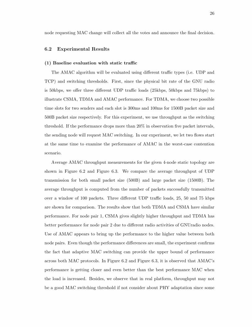
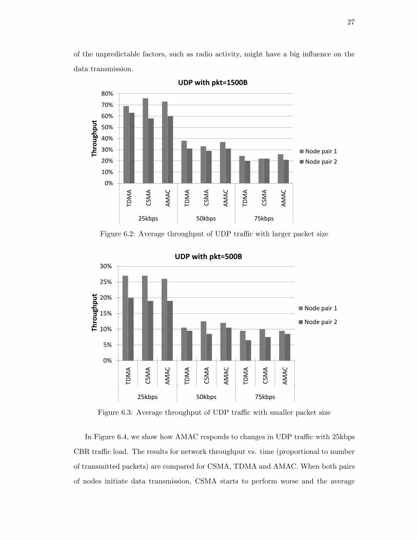
Average AMAC throughput measurements for the given 4-node static topology are

shown in Figure 6.2 and Figure 6.3. We compare the average throughput of UDP

transmission for both small packet size (500B) and large packet size (1500B). The

average throughput is computed from the number of packets successfully transmitted

over a window of 100 packets. Three different UDP traffic loads, 25, 50 and 75 kbps

are shown for comparison. The results show that both TDMA and CSMA have similar

performance. For node pair 1, CSMA gives slightly higher throughput and TDMA has

better performance for node pair 2 due to different radio activities of GNUradio nodes.

Use of AMAC appears to bring up the performance to the higher value between both

node pairs. Even though the performance differences are small, the experiment confirms

the fact that adaptive MAC switching can provide the upper bound of performance

across both MAC protocols. In Figure 6.2 and Figure 6.3, it is observed that AMAC’s

performance is getting closer and even better than the best performance MAC when

the load is increased. Besides, we observe that in real platform, throughput may not

be a good MAC switching threshold if not consider about PHY adaptation since some

27

of the unpredictable factors, such as radio activity, might have a big influence on the

data transmission.

30%

40%

50%

60%

70%

80%T

hro

ug

hp

ut

UDP with pkt=1500B

Node pair 1

0%

10%

20%

30%

TD

MA

CS

MA

AM

AC

TD

MA

CS

MA

AM

AC

TD

MA

CS

MA

AM

AC

25kbps 50kbps 75kbps

Th

rou

gh

pu

t

Node pair 1

Node pair 2

Figure 6.2: Average throughput of UDP traffic with larger packet size

15%

20%

25%

30%

Th

rou

gh

pu

t

UDP with pkt=500B

Node pair 1

Node pair 2

0%

5%

10%

TD

MA

CS

MA

AM

AC

TD

MA

CS

MA

AM

AC

TD

MA

CS

MA

AM

AC

25kbps 50kbps 75kbps

Th

rou

gh

pu

t

Node pair 2

Figure 6.3: Average throughput of UDP traffic with smaller packet size

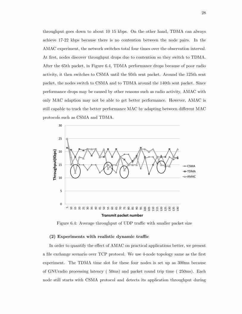
In Figure 6.4, we show how AMAC responds to changes in UDP traffic with 25kbps

CBR traffic load. The results for network throughput vs. time (proportional to number

of transmitted packets) are compared for CSMA, TDMA and AMAC. When both pairs

of nodes initiate data transmission, CSMA starts to perform worse and the average

28

throughput goes down to about 10 15 kbps. On the other hand, TDMA can always

achieve 17-22 kbps because there is no contention between the node pairs. In the

AMAC experiment, the network switches total four times over the observation interval.

At first, nodes discover throughput drops due to contention so they switch to TDMA.

After the 65th packet, in Figure 6.4, TDMA performance drops because of poor radio

activity, it then switches to CSMA until the 95th sent packet. Around the 125th sent

packet, the nodes switch to CSMA and to TDMA around the 140th sent packet. Since

performance drops may be caused by other reasons such as radio activity, AMAC with

only MAC adaption may not be able to get better performance. However, AMAC is

still capable to track the better performance MAC by adapting between different MAC

protocols such as CSMA and TDMA.

15

20

25

30

Th

rou

gh

pu

t(K

bp

s)

CSMA

TDMA

0

5

10

5

10

15

20

25

30

35

40

45

50

55

60

65

70

75

80

85

90

95

100

105

110

115

120

125

130

135

140

Th

rou

gh

pu

t(K

bp

s)

Transmit packet number

TDMA

AMAC

Figure 6.4: Average throughput of UDP traffic with smaller packet size

(2) Experiments with realistic dynamic traffic

In order to quantify the effect of AMAC on practical applications better, we present

a file exchange scenario over TCP protocol. We use 4-node topology same as the first

experiment. The TDMA time slot for these four nodes is set up as 300ms because

of GNUradio processing latency ( 50ms) and packet round trip time ( 250ms). Each

node still starts with CSMA protocol and detects its application throughput during

29

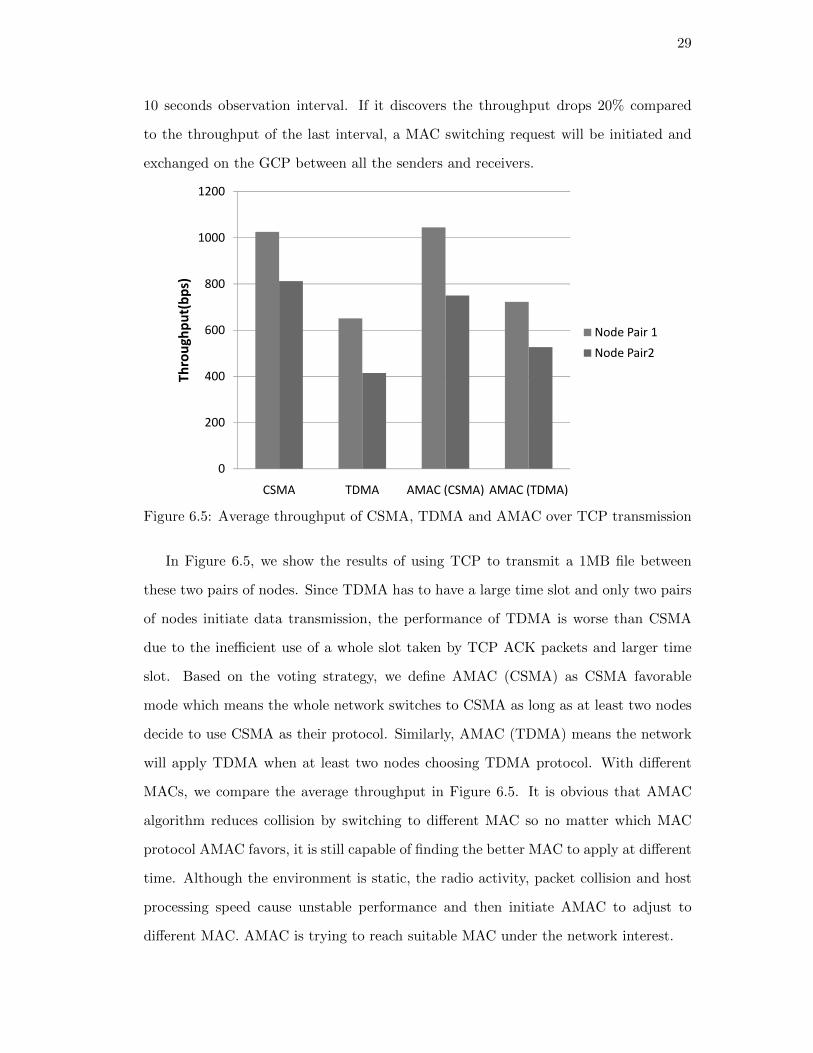
10 seconds observation interval. If it discovers the throughput drops 20% compared

to the throughput of the last interval, a MAC switching request will be initiated and

exchanged on the GCP between all the senders and receivers.

600

800

1000

1200Throughput(bps)

Node Pair 1

0

200

400

CSMA TDMA AMAC (CSMA) AMAC (TDMA)

Throughput(bps)

Node Pair2

Figure 6.5: Average throughput of CSMA, TDMA and AMAC over TCP transmission

In Figure 6.5, we show the results of using TCP to transmit a 1MB file between

these two pairs of nodes. Since TDMA has to have a large time slot and only two pairs

of nodes initiate data transmission, the performance of TDMA is worse than CSMA

due to the inefficient use of a whole slot taken by TCP ACK packets and larger time

slot. Based on the voting strategy, we define AMAC (CSMA) as CSMA favorable

mode which means the whole network switches to CSMA as long as at least two nodes

decide to use CSMA as their protocol. Similarly, AMAC (TDMA) means the network

will apply TDMA when at least two nodes choosing TDMA protocol. With different

MACs, we compare the average throughput in Figure 6.5. It is obvious that AMAC

algorithm reduces collision by switching to different MAC so no matter which MAC

protocol AMAC favors, it is still capable of finding the better MAC to apply at different

time. Although the environment is static, the radio activity, packet collision and host

processing speed cause unstable performance and then initiate AMAC to adjust to

different MAC. AMAC is trying to reach suitable MAC under the network interest.

30

(3) Experiments with dynamic applications

GNUradio

802.11b

Node1 Node2

GNUradio

802.11b60 feet

Flow1 Flow2

Node3

GNUradio

802.11b

GNUradio

802.11b

60 feet

60 feet

60 feet

GNUradio

802.11b

Node5

Node4

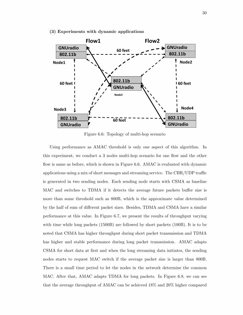
Figure 6.6: Topology of multi-hop scenario

Using performance as AMAC threshold is only one aspect of this algorithm. In

this experiment, we conduct a 3 nodes multi-hop scenario for one flow and the other

flow is same as before, which is shown in Figure 6.6. AMAC is evaluated with dynamic

applications using a mix of short messages and streaming service. The CBR/UDP traffic

is generated in two sending nodes. Each sending node starts with CSMA as baseline

MAC and switches to TDMA if it detects the average future packets buffer size is

more than some threshold such as 800B, which is the approximate value determined

by the half of sum of different packet sizes. Besides, TDMA and CSMA have a similar

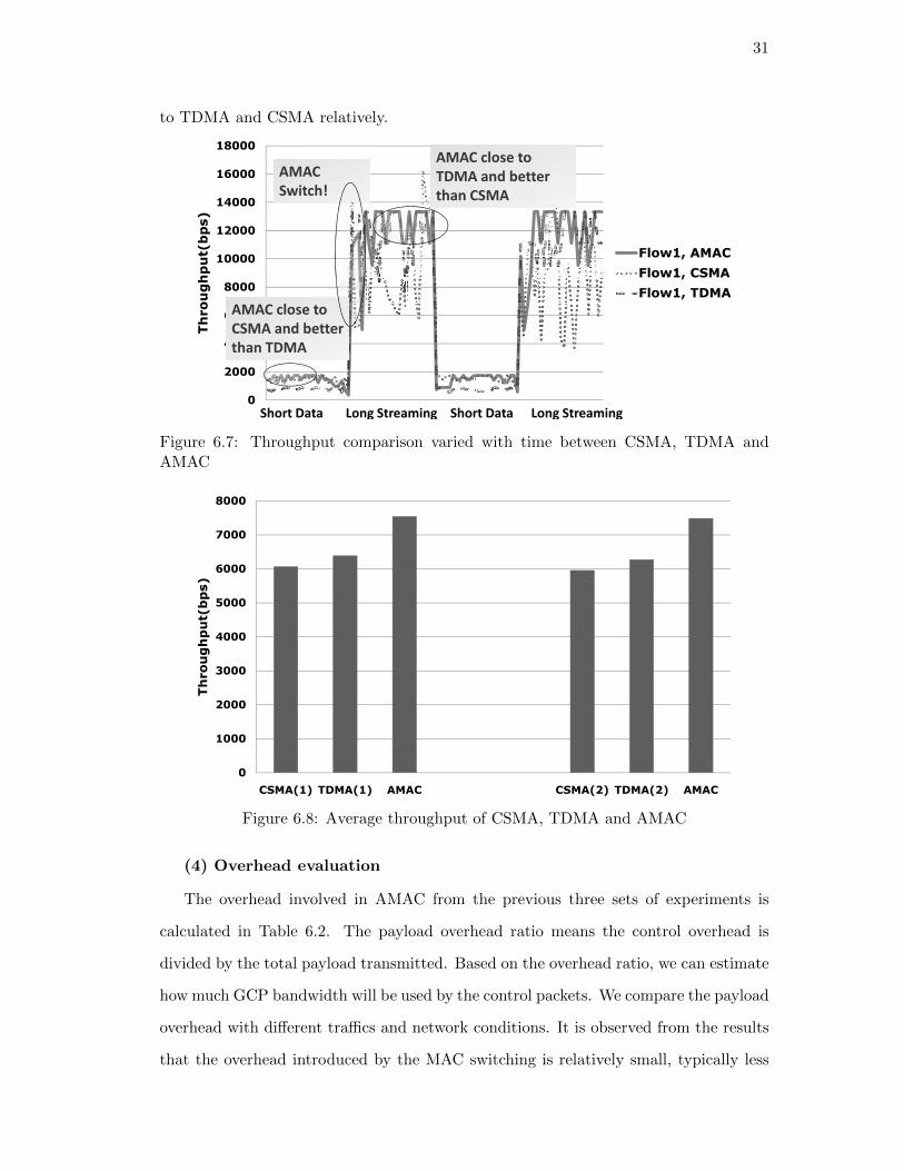
performance at this value. In Figure 6.7, we present the results of throughput varying

with time while long packets (1500B) are followed by short packets (100B). It is to be

noted that CSMA has higher throughput during short packet transmission and TDMA

has higher and stable performance during long packet transmission. AMAC adapts

CSMA for short data at first and when the long streaming data initiates, the sending

nodes starts to request MAC switch if the average packet size is larger than 800B.

There is a small time period to let the nodes in the network determine the common

MAC. After that, AMAC adapts TDMA for long packets. In Figure 6.8, we can see

that the average throughput of AMAC can be achieved 18% and 20% higher compared

31

to TDMA and CSMA relatively.

10000

12000

14000

16000

18000

Throughput(bps)

Flow1, AMAC

Flow1, CSMA

AMAC

Switch!

AMAC close to

TDMA and better

than CSMA

0

2000

4000

6000

8000

Throughput(bps)

Flow1, CSMA

Flow1, TDMA

AMAC close to

CSMA and better

than TDMA

Short Data Short Data Long StreamingLong Streaming

Figure 6.7: Throughput comparison varied with time between CSMA, TDMA andAMAC

4000

5000

6000

7000

8000

Throughput(bps)

0

1000

2000

3000

4000

CSMA(1) TDMA(1) AMAC CSMA(2) TDMA(2) AMAC

Throughput(bps)

Figure 6.8: Average throughput of CSMA, TDMA and AMAC

(4) Overhead evaluation

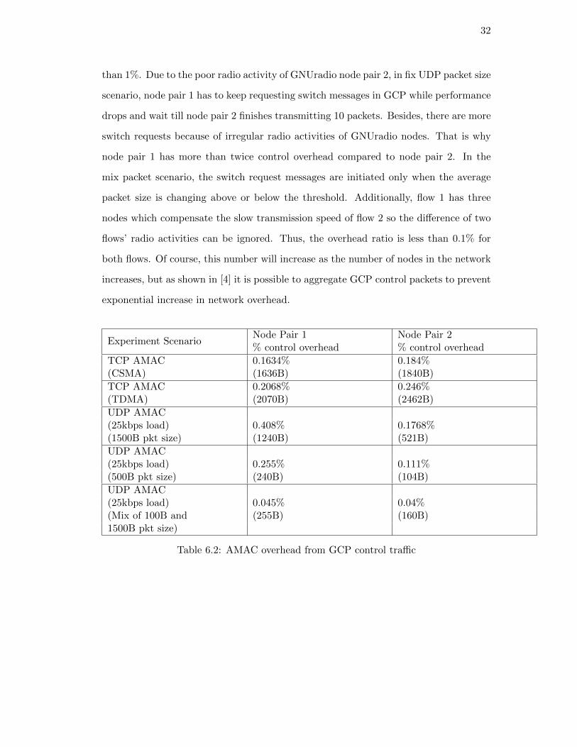
The overhead involved in AMAC from the previous three sets of experiments is

calculated in Table 6.2. The payload overhead ratio means the control overhead is

divided by the total payload transmitted. Based on the overhead ratio, we can estimate

how much GCP bandwidth will be used by the control packets. We compare the payload

overhead with different traffics and network conditions. It is observed from the results

that the overhead introduced by the MAC switching is relatively small, typically less

32

than 1%. Due to the poor radio activity of GNUradio node pair 2, in fix UDP packet size

scenario, node pair 1 has to keep requesting switch messages in GCP while performance

drops and wait till node pair 2 finishes transmitting 10 packets. Besides, there are more

switch requests because of irregular radio activities of GNUradio nodes. That is why

node pair 1 has more than twice control overhead compared to node pair 2. In the

mix packet scenario, the switch request messages are initiated only when the average

packet size is changing above or below the threshold. Additionally, flow 1 has three

nodes which compensate the slow transmission speed of flow 2 so the difference of two

flows’ radio activities can be ignored. Thus, the overhead ratio is less than 0.1% for

both flows. Of course, this number will increase as the number of nodes in the network

increases, but as shown in [4] it is possible to aggregate GCP control packets to prevent

exponential increase in network overhead.

Experiment ScenarioNode Pair 1 Node Pair 2% control overhead % control overhead

TCP AMAC 0.1634% 0.184%(CSMA) (1636B) (1840B)

TCP AMAC 0.2068% 0.246%(TDMA) (2070B) (2462B)

UDP AMAC(25kbps load) 0.408% 0.1768%(1500B pkt size) (1240B) (521B)

UDP AMAC(25kbps load) 0.255% 0.111%(500B pkt size) (240B) (104B)

UDP AMAC(25kbps load) 0.045% 0.04%(Mix of 100B and (255B) (160B)1500B pkt size)

Table 6.2: AMAC overhead from GCP control traffic

33

Chapter 7

Conclusion

In this thesis, AMAC algorithm is presented by using GCP-based control framework in

cognitive radio network. Each node has ability to determine when to choose suitable

MAC protocol and the network has ability to reach the common MAC protocol based

on most nodes’ interests. We have experimentally studied the AMAC protocol and

selected different scenarios for NS-2 simulation. With different traffic types, AMAC

protocol is able to adapt well and reach 20% more throughput compare to single MAC

protocol. In mobile scenario, AMAC is able to preserve specific service requirement

and balance the performance of different types network by PHY and MAC adaptation.

Our proof-of-concept implementation with GNU radios shows that it is possible to

implement dynamic MAC switching in cognitive radios networks using the capabilities

of the control plane protocol. In a static environment, Experimental results with a small

network show that AMAC is still able to track the better performance of candidate MAC

protocols even without PHY adaptation. The results also present MAC switching can

provide performance improvements in dynamic application environments, and show

that switching latency and control overhead are not excessive.

34

References

[1] J.Mitola. Cognitive Radio: An Integrated Agent Architecture for Software Radio.PhD thesis, Royal Institute of Technology (KTH), 2000.

[2] D. Maldonado, B. Le, A. Hugine, T. W. Rondeau, and C. W. Bostian. Cognitiveradio applications to dynamic spectrum allocation: a discussion and an illustrativeexample. In IEEE DySPAN, pages 597–600, 2005.

[3] Allocation Networks Jun and Jun Zhao. Distributed coordination in dynamicspectrum. In IEEE DySPAN, pages 259–268, 2005.

[4] Xiangpeng Jing and Dipankar Raychaudhuri. Global control plane architecture forcognitive radio networks. In ICC, pages 6466–6470, 2007.

[5] Xiangpeng Jing, Shanmuga S Anandaraman, Mesut Ali Ergin, Ivan Seskar, andDipankar Raychaudhuri. Distributed coordination schemes for multi-radio co-existence in dense spectrum environments: An experimental study on the orbittestbed. In IEEE DySPAN, pages 597–600, 2008.

[6] D. Raychaudhuri. Orbit: Open-access research testbed for next-generation wirelessnetworks. NSF Network Research Testbeds Program, NSF award ANI-0335244,2003.

[7] N. Jain, S. Das, and A. Nasipuri. A multichannel csma mac protocol with receiver-based channel selection for multihop wireless networks. In ICCCN 2001, 2001.

[8] Xiangpeng Jing and Dipankar Raychaudhuri. A spectrum etiquette protocol for ef-ficient coordination of radio devices in unlicensed bands. In Proceedings of PIMRC,2003.

[9] Carlos Cordeiro and Kiran Challapali. C-mac: A cognitive mac protocol for multi-channel wireless networks. In IEEE DySPAN, 2007.

[10] C. Doerr, M. Neufeld, J. Fifield, T. Weingart, D.C. Sicker, and D Grunwald.Multimac - an adaptive mac framework for dynamic radio networking. In IEEEDySPAN, 2005.

[11] Rahul Dhar, Gesly George, Amit Malani, and Peter Steenkiste. Supporting inte-grated mac and phy software development for the usrp sdr. In IEEE Workshop onNetworking Technologies for Software Defined Radio (SDR) Networks, 2006.

[12] George Nychis, Thibaud Hottelier, Zhuochen Yang, Srinivasan Seshan, and PeterSteenkiste. Enabling mac protocol implementations on software-defined radios. InNetworked Systems Design and Implementation, 2009.

35

[13] K. Mandke, Soon-Hyeok Choi, Gibeom Kim, R. Grant, R. C. Daniels, WonsooKim, Robert W. Heath Jr, and S. Nettles. Early results on hydra: A flexiblemac/phy multihop testbed. In the Proc. of the IEEE Vehic. Tech. Conference,2007.

[14] Minden, G. J. Evans, J. B. Searl, L. Depardo, D. Petty, V. R. Rajbanshi, R. New-man, T. Chen, and G. Weidling. Kuar: A flexible software-defined radio develop-ment platform. In IEEE Dyspan 07, 2007.

36

Appendix A

Appendix

Node protocolagent

routingagent

addrclassifier

portclassifier

255

defaulttarget_

RPRNodeCtrl-agent (Bootstrap, Discovery, AMAC-ctrl)

Data-agent ( AMAC-data)

ARP LLLL

PHY-Ctrl

CHANNEL-Ctrl

MAC Ctrl-802.11 MAC Data-CSMA, TDMA

PHY-Data

CHANNEL-Data

ARP

IFQ IFQ

Figure A.1: NS-2 programming flow chart

37

Ctrl-plane

Data-plane

Beacon Neighbor

Discovery

AMAC

control

Socket

Data Packet Generator

TCP UDP

AMAC Algorithm

CSMA TDMA

APIOrbit Radio

Node

(802.11b)

GNU-radio

Node

(400MHz)

Discovery control

message

PHY - GMSK

Figure A.2: GNUradio programming stacks


Recommended