Page 1
MAC Protocol for Wireless Network on Chip
i
Technical report, IDE1052, February 2011
MAC Protocol for Wireless Network on Chip
Master’s Thesis in Computer Systems Engineering
Muhammad Ilyas & Saad Ahmed
School of Information Science, Computer and Electrical Engineering
Halmstad University
Page 2
MAC Protocol for Wireless Network on Chip
ii
MAC Protocol for Wireless Network on Chip
Master Thesis in Computer System Engineering
School of Information Science, Computer and Electrical Engineering
Halmstad University
Box 823, S-301 18 Halmstad, Sweden
February 2011
Page 3
MAC Protocol for Wireless Network on Chip
iii
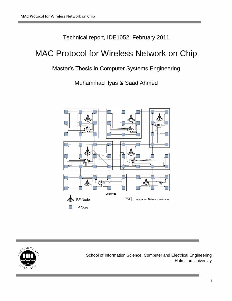
Description of cover page picture/figure: It is our Proposed Architecture (2-D Mesh Architecture with
cluster cores directly wired connected to TNI)
Page 4
MAC Protocol for Wireless Network on Chip
iv
Preface
This Master’s thesis in Computer Systems Engineering has been conducted at the School of Information Science,
Computer and Electrical Engineering at Halmstad University, as part of degree program. We would like to thank
Mr. Urban Bilstrup and Mr. Bertil Svensson for providing us an opportunity to work on this thesis under there
supervision and guidance throughout the project.
Further we would like to thank Almighty ALLAH and grateful to our parents, brothers and sisters who always
supported and encouraged us during our stay and study in Sweden.
Muhammad Ilyas & Saad Ahmed
Halmstad University, February 2011
Page 5
MAC Protocol for Wireless Network on Chip
v
Page 6
MAC Protocol for Wireless Network on Chip
vi
Abstract
In this paper, analysis of efficient medium access control (MAC) protocol for resolving channel
contention and minimizing collision probability through consideration of different WNoC architectures
is discussed. In this analysis we study the different channel access mechanisms for WNoC in our
proposed architecture. Further we also discussed some possible architectures for WNoC.
Page 7
MAC Protocol for Wireless Network on Chip
vii
Contents Preface ................................................................................................................................................................iv
Abstract ...............................................................................................................................................................vi
1 Introduction ...................................................................................................................................................... 1
1.1 Integrated Circuits (ICs) ........................................................................................................................ 1
1.2 Silicon technology and System on Chip (SoC) ........................................................................................ 1
1.3 Interconnection of System on Chip ....................................................................................................... 2
1.3.1 Direct interconnection .................................................................................................................. 2
1.3.2 Busses .......................................................................................................................................... 3
1.3.3 Network on Chip (NoC) ................................................................................................................. 4
1.3.4 Wireless Network on Chip (WNoC)................................................................................................ 6
1.4 Thesis motivation and objective ........................................................................................................... 7
2 Theoretical Background ............................................................................................................................... 8
2.1 OSI Reference Model for Network Communication .............................................................................. 8
2.2 OSI model layers in WNoC context ....................................................................................................... 9
2.2.1 Physical Layer ............................................................................................................................... 9
2.2.2 Data Link Layer ............................................................................................................................. 9
2.2.3 Network layer ............................................................................................................................... 9
2.3 Medium Access Issues in WNoC Context ............................................................................................ 10
2.4 Network Topology .............................................................................................................................. 11
2.4.1 Bus Topology: ............................................................................................................................. 11
2.4.2 Ring Topology: ............................................................................................................................ 11
2.4.3 Mesh Topology: .......................................................................................................................... 11
2.4.4 Star Topology: ............................................................................................................................ 11
Page 8
MAC Protocol for Wireless Network on Chip
viii
2.4.5 Tree Topology: ............................................................................................................................ 12
3 Medium Access Protocols for Wireless Networks ....................................................................................... 13
3.1 Multiple Access Protocols ................................................................................................................... 13
3.1.1 ALOHA ............................................................................................................................................... 13
3.1.2 CSMA .......................................................................................................................................... 13
3.1.3 BTMA ......................................................................................................................................... 13
3.1.4 Carrier Sense Multiple Access/Collision Avoidance (CSMA/CA) ................................................... 14
3.2 Slotted ALOHA .................................................................................................................................... 14
3.3 Reservation ALOHA (R-ALOHA) ........................................................................................................... 14
3.4 Fixed Assignment Protocols ................................................................................................................ 15
3.4.1 TDMA ......................................................................................................................................... 15
3.4.2 CDMA (Code Division Multiple Access) ........................................................................................ 15
3.4.3 Frequency Division Multiple Access ............................................................................................ 16
3.4.4 MCCDMA .................................................................................................................................... 17
4 Architectures for WNoC ............................................................................................................................. 19
4.1 Adjacent RF nodes wired and wireless interconnection ...................................................................... 19
4.1.1 Advantages ................................................................................................................................. 20
4.1.2 Disadvantages ............................................................................................................................ 21
4.2 Fully connected RF nodes wired and wirelessly ................................................................................... 21
4.2.1 Advantages ................................................................................................................................. 23
4.2.2 Disadvantages ............................................................................................................................ 23
4.3 2-D Mesh with cluster cores wired connection to TNI through common node .................................... 23
4.3.1 Advantages ................................................................................................................................. 25
4.3.2 Disadvantages ............................................................................................................................ 25
Page 9
MAC Protocol for Wireless Network on Chip
ix
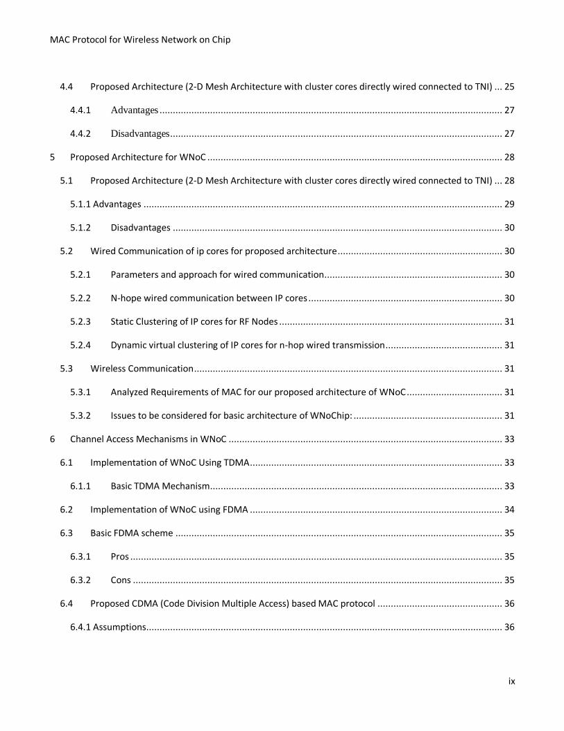
4.4 Proposed Architecture (2-D Mesh Architecture with cluster cores directly wired connected to TNI) ... 25
4.4.1 Advantages ................................................................................................................................. 27
4.4.2 Disadvantages ............................................................................................................................. 27
5 Proposed Architecture for WNoC ............................................................................................................... 28
5.1 Proposed Architecture (2-D Mesh Architecture with cluster cores directly wired connected to TNI) ... 28
5.1.1 Advantages ....................................................................................................................................... 29
5.1.2 Disadvantages ............................................................................................................................ 30
5.2 Wired Communication of ip cores for proposed architecture .............................................................. 30
5.2.1 Parameters and approach for wired communication................................................................... 30
5.2.2 N-hope wired communication between IP cores ......................................................................... 30
5.2.3 Static Clustering of IP cores for RF Nodes .................................................................................... 31
5.2.4 Dynamic virtual clustering of IP cores for n-hop wired transmission ............................................ 31
5.3 Wireless Communication .................................................................................................................... 31
5.3.1 Analyzed Requirements of MAC for our proposed architecture of WNoC .................................... 31
5.3.2 Issues to be considered for basic architecture of WNoChip: ........................................................ 31
6 Channel Access Mechanisms in WNoC ....................................................................................................... 33
6.1 Implementation of WNoC Using TDMA ............................................................................................... 33
6.1.1 Basic TDMA Mechanism.............................................................................................................. 33
6.2 Implementation of WNoC using FDMA ............................................................................................... 34
6.3 Basic FDMA scheme ........................................................................................................................... 35
6.3.1 Pros ............................................................................................................................................ 35
6.3.2 Cons ........................................................................................................................................... 35
6.4 Proposed CDMA (Code Division Multiple Access) based MAC protocol ............................................... 36
6.4.1 Assumptions ...................................................................................................................................... 36
Page 10
MAC Protocol for Wireless Network on Chip
x
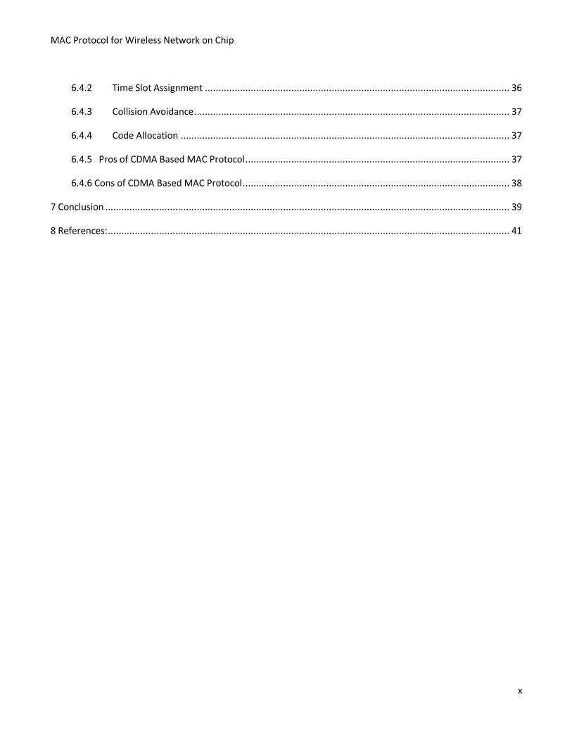
6.4.2 Time Slot Assignment ................................................................................................................. 36
6.4.3 Collision Avoidance ..................................................................................................................... 37
6.4.4 Code Allocation .......................................................................................................................... 37
6.4.5 Pros of CDMA Based MAC Protocol .................................................................................................. 37
6.4.6 Cons of CDMA Based MAC Protocol ................................................................................................... 38
7 Conclusion ...................................................................................................................................................... 39
8 References: ..................................................................................................................................................... 41
Page 11
MAC Protocol for Wireless Network on Chip
xi
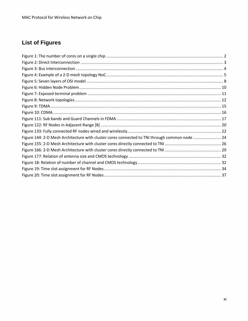
List of Figures
Figure 1: The number of cores on a single chip .................................................................................................... 2
Figure 2: Direct Interconnection .......................................................................................................................... 3
Figure 3: Bus Interconnection .............................................................................................................................. 4
Figure 4: Example of a 2-D mesh topology NoC .................................................................................................... 5
Figure 5: Seven layers of OSI model ..................................................................................................................... 8
Figure 6: Hidden Node Problem ......................................................................................................................... 10
Figure 7: Exposed terminal problem .................................................................................................................. 11
Figure 8: Network topologies ............................................................................................................................. 12
Figure 9: TDMA .................................................................................................................................................. 15
Figure 10: CDMA ................................................................................................................................................ 16
Figure 111: Sub bands and Guard Channels in FDMA ......................................................................................... 17
Figure 122: RF Nodes in Adjacent Range [8] ....................................................................................................... 20
Figure 133: Fully connected RF nodes wired and wirelessly ................................................................................ 22
Figure 144: 2-D Mesh Architecture with cluster cores connected to TNI through common node ........................ 24
Figure 155: 2-D Mesh Architecture with cluster cores directly connected to TNI ................................................ 26
Figure 166: 2-D Mesh Architecture with cluster cores directly connected to TNI ................................................ 29
Figure 177: Relation of antenna size and CMOS technology ............................................................................... 32
Figure 18: Relation of number of channel and CMOS technology ....................................................................... 32
Figure 19: Time slot assignment for RF Nodes .................................................................................................... 34
Figure 20: Time slot assignment for RF Nodes .................................................................................................... 37
Page 12
MAC Protocol for Wireless Network on Chip
1
1 Introduction
In this paper, analysis of efficient medium access control (MAC) protocol for resolving channel
contention and minimizing collision probability through consideration of different WNoC architectures
is discussed.
1.1 Integrated Circuits (ICs)
In modern era several digital devices are being introduced. These digital devices range from small
embedded controllers, efficient processors in small devices to very high performance processors. These
controllers and processors are highly integrated circuits (ICs). Jack Kilby was the first one to combine
transistors into an IC in 1958. The combination of large number of transistors into an IC has resulted in
the present VLSI (very large scale integration) designs. As the number of ICs increased with the
increasing processing demand, the complexity of their interconnection also increased. Multi-processor
systems on chip (MPSoCs) consisting of complex integrated circuits in different embedded systems are
communicating with each other in very high speed. The intercommunication requirement of MPSoCs
made of hundreds of cores will not be feasible using a single shared bus or direct interconnection due to
their poor scalability with system size.
1.2 Silicon technology and System on Chip (SoC)
Over the last decade, the intercommunication requirement of different cores through direct
interconnection and shared buses could no longer continue because of power, shared bandwidth and
memory constraints. Multiple identical cores were integrated on a single chip. The rapid improvement in
silicon technology provides semiconductor a new horizon. The number of transistors has significantly
increased on a chip. There can be one billion transistors on advanced integrated circuits(IC) that makes
the designs process more complex. To reduce such complexity, system on chip (SoC) provides an
intercommunication by which a large number of cores can be interconnect on a single chip. A SoC does
not necessarily consist of many identical cores, it may integrate a heterogeneous set of modules into a
single chip. The integration of processing cores memory blocks and peripherals, reduces the overall size
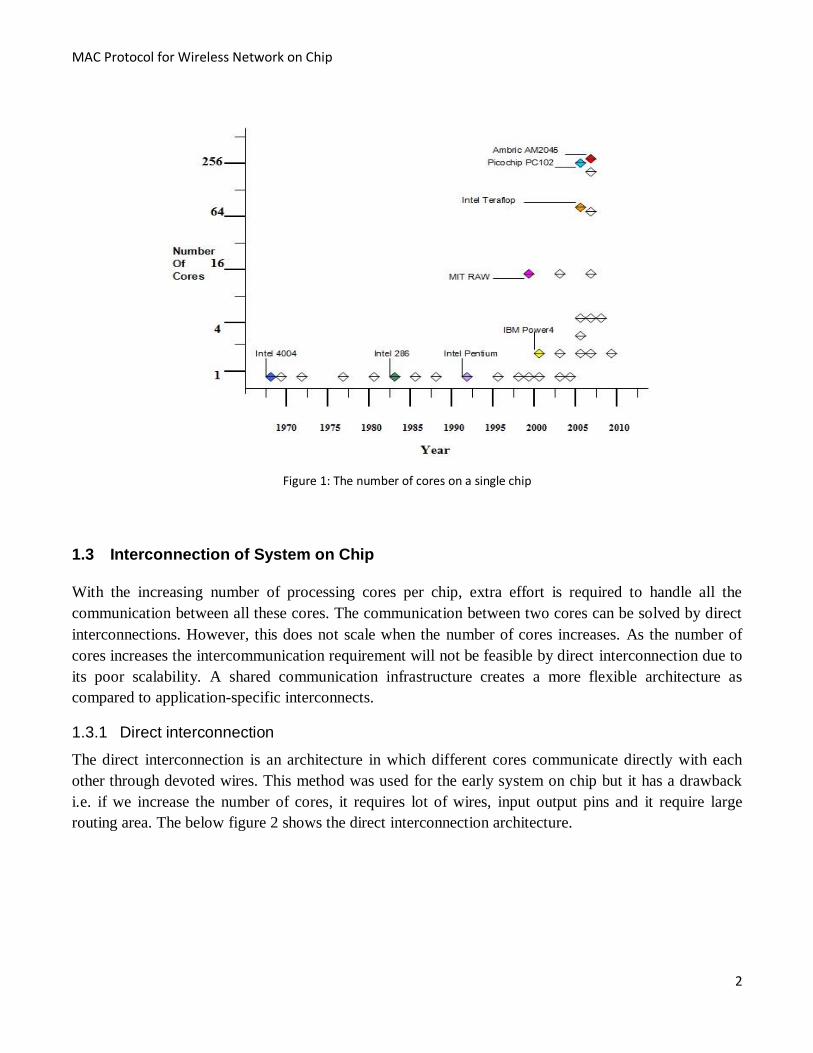
of the system. The below figure 1 shows [4] the number of cores of different companies on a single chip
in several years.
Page 13
MAC Protocol for Wireless Network on Chip
2
Figure 1: The number of cores on a single chip
1.3 Interconnection of System on Chip
With the increasing number of processing cores per chip, extra effort is required to handle all the
communication between all these cores. The communication between two cores can be solved by direct
interconnections. However, this does not scale when the number of cores increases. As the number of
cores increases the intercommunication requirement will not be feasible by direct interconnection due to
its poor scalability. A shared communication infrastructure creates a more flexible architecture as
compared to application-specific interconnects.
1.3.1 Direct interconnection
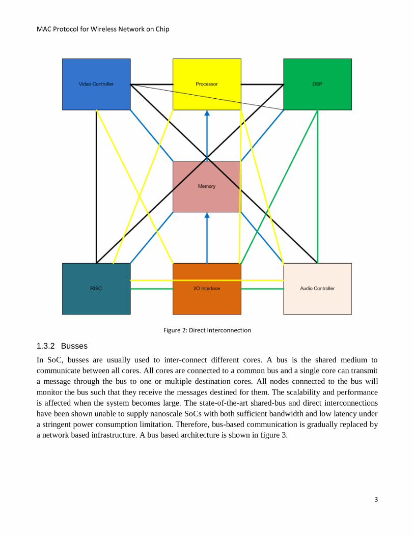
The direct interconnection is an architecture in which different cores communicate directly with each
other through devoted wires. This method was used for the early system on chip but it has a drawback
i.e. if we increase the number of cores, it requires lot of wires, input output pins and it require large
routing area. The below figure 2 shows the direct interconnection architecture.
Page 14
MAC Protocol for Wireless Network on Chip
3
Figure 2: Direct Interconnection
1.3.2 Busses
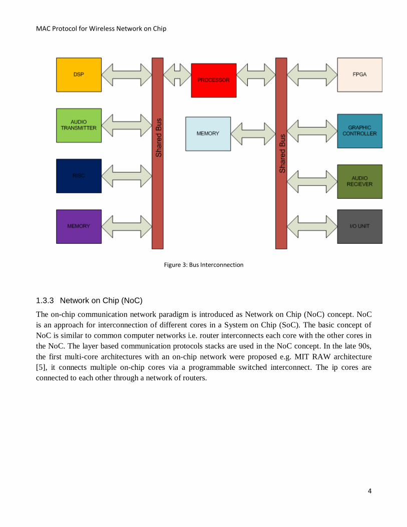
In SoC, busses are usually used to inter-connect different cores. A bus is the shared medium to
communicate between all cores. All cores are connected to a common bus and a single core can transmit
a message through the bus to one or multiple destination cores. All nodes connected to the bus will
monitor the bus such that they receive the messages destined for them. The scalability and performance
is affected when the system becomes large. The state-of-the-art shared-bus and direct interconnections
have been shown unable to supply nanoscale SoCs with both sufficient bandwidth and low latency under
a stringent power consumption limitation. Therefore, bus-based communication is gradually replaced by
a network based infrastructure. A bus based architecture is shown in figure 3.
Page 15
MAC Protocol for Wireless Network on Chip
4
Figure 3: Bus Interconnection
1.3.3 Network on Chip (NoC)
The on-chip communication network paradigm is introduced as Network on Chip (NoC) concept. NoC
is an approach for interconnection of different cores in a System on Chip (SoC). The basic concept of
NoC is similar to common computer networks i.e. router interconnects each core with the other cores in
the NoC. The layer based communication protocols stacks are used in the NoC concept. In the late 90s,
the first multi-core architectures with an on-chip network were proposed e.g. MIT RAW architecture
[5], it connects multiple on-chip cores via a programmable switched interconnect. The ip cores are
connected to each other through a network of routers.
Page 16
MAC Protocol for Wireless Network on Chip
5
Transistors are interconnected in 2-D mesh which puts constraints on topology of network. The
advantage of an on-chip network is that it represents a relatively controlled environment and fixed
organization of the network once the chip is design. The NoC interconnect various components of a
single vlsi architecture. These components range from small processing units to very high processing
units. The NoC transports data between those components and we refer to the combination of the NoC
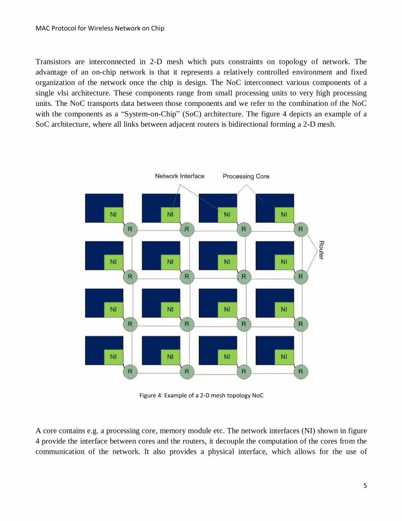
with the components as a “System-on-Chip” (SoC) architecture. The figure 4 depicts an example of a
SoC architecture, where all links between adjacent routers is bidirectional forming a 2-D mesh.
Figure 4: Example of a 2-D mesh topology NoC
A core contains e.g. a processing core, memory module etc. The network interfaces (NI) shown in figure
4 provide the interface between cores and the routers, it decouple the computation of the cores from the
communication of the network. It also provides a physical interface, which allows for the use of
Page 17
MAC Protocol for Wireless Network on Chip
6
different clock and voltage domains for the network and the cores. Routers perform the transportation of
data among different cores through the links. They handle network packets according to the chosen
network protocol i.e. (Read Request Protocol and Write Request protocol). The packet’s items can be
buffered in the router and forwarded via the links to the successive router following the packet’s route
from source to destination. NoC is a replacement for direct interconnection and single bus architectures.
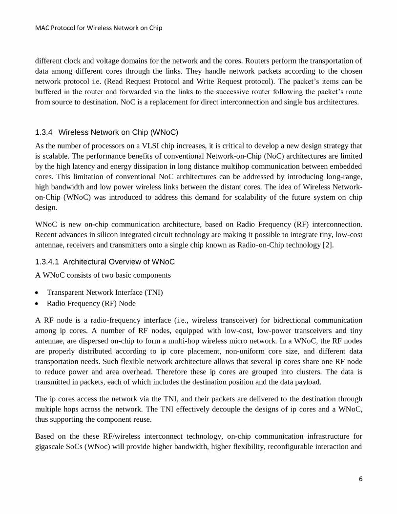
1.3.4 Wireless Network on Chip (WNoC)
As the number of processors on a VLSI chip increases, it is critical to develop a new design strategy that
is scalable. The performance benefits of conventional Network-on-Chip (NoC) architectures are limited
by the high latency and energy dissipation in long distance multihop communication between embedded
cores. This limitation of conventional NoC architectures can be addressed by introducing long-range,
high bandwidth and low power wireless links between the distant cores. The idea of Wireless Network-
on-Chip (WNoC) was introduced to address this demand for scalability of the future system on chip
design.
WNoC is new on-chip communication architecture, based on Radio Frequency (RF) interconnection.
Recent advances in silicon integrated circuit technology are making it possible to integrate tiny, low-cost
antennae, receivers and transmitters onto a single chip known as Radio-on-Chip technology [2].
1.3.4.1 Architectural Overview of WNoC
A WNoC consists of two basic components
Transparent Network Interface (TNI)
Radio Frequency (RF) Node
A RF node is a radio-frequency interface (i.e., wireless transceiver) for bidrectional communication
among ip cores. A number of RF nodes, equipped with low-cost, low-power transceivers and tiny
antennae, are dispersed on-chip to form a multi-hop wireless micro network. In a WNoC, the RF nodes
are properly distributed according to ip core placement, non-uniform core size, and different data
transportation needs. Such flexible network architecture allows that several ip cores share one RF node
to reduce power and area overhead. Therefore these ip cores are grouped into clusters. The data is
transmitted in packets, each of which includes the destination position and the data payload.
The ip cores access the network via the TNI, and their packets are delivered to the destination through
multiple hops across the network. The TNI effectively decouple the designs of ip cores and a WNoC,
thus supporting the component reuse.
Based on the these RF/wireless interconnect technology, on-chip communication infrastructure for
gigascale SoCs (WNoc) will provide higher bandwidth, higher flexibility, reconfigurable interaction and
Page 18
MAC Protocol for Wireless Network on Chip
7
freed up wiring as compared to NoC [2]. The cores access the network via transparent network interface
and their packets are forwarded to destination through a multi-hop routing path. When many RF nodes
in WNoC communicate over the shared wireless medium, collisions may occur when more than one RF
node tries to transmit data simultaneously. Thus, development of efficient medium access control
(MAC) is a typical challenge for WNoC for resolving channel contention and avoiding collisions.
Wireless MAC protocol can be classified into two broad categories, distributed and centralized
according to the network architecture or contention/schedule based according to the channel access
policies.
WMAC protocols can be synchronous or non-synchronous. Non-synchronous protocols are largely
contention-based. Most synchronized protocols employ a centralized scheduler to make sure that nodes
follow some particular schedules to achieve collision-free data transmission.
1.4 Thesis motivation and objective
Recent system-on-chips hold a large variety of functionalities on a single silicon chip which includes
microprocessors, memories, DSP, FPGA, peripherals and analog modules etc. The common techniques
used for communication among these cores are not sufficient due to poor scalability and reusability.
Network-on-chip has thus been introduced to overcome these problems but, due to very large scale
integration of heterogeneous ip cores, wired on chip interconnection between them cause’s issues like
cross talk noise and scaling etc [2]. The wireless-network-on-chip consists of two main components i.e.:
Radio Frequency Node (RF node) and Transparent Network Interface (TNI). The RF node has a radio-
frequency interface (i.e., wireless transceiver) for bidirectional communication among ip cores. A
number of RF nodes, equipped with low-cost, low-power transceivers and tiny antennae, are dispersed
on-chip to form a multi-hop wireless micro network. We will focus on the theoretical design of efficient
medium access control (MAC) protocol for resolving channel contention and minimizing collision
probability in different WNoC architectures.When many RF nodes in WNoC communicate over the
shared wireless medium, collisions may occur if multiple nearby RF nodes transmit data simultaneously.
The system performance significantly degrades as the receiver in the collision domain (i.e., an area
where all nodes are within each other’s transmission range) cannot receive the data packet correctly.
Thus a challenge for WNoC is to design efficient medium access control (MAC) protocol for resolving
channel contention and minimizing collision probability.
Page 19
MAC Protocol for Wireless Network on Chip
8
2 Theoretical Background
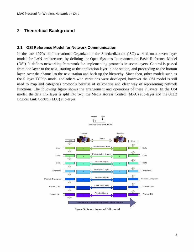
2.1 OSI Reference Model for Network Communication
In the late 1970s the International Organization for Standardization (ISO) worked on a seven layer
model for LAN architectures by defining the Open Systems Interconnection Basic Reference Model
(OSI). It defines networking framework for implementing protocols in seven layers. Control is passed
from one layer to the next, starting at the application layer in one station, and proceeding to the bottom
layer, over the channel to the next station and back up the hierarchy. Since then, other models such as
the 5 layer TCP/ip model and others with variations were developed, however the OSI model is still
used to map and categories protocols because of its concise and clear way of representing network
functions. The following figure shows the arrangement and operations of these 7 layers. In the OSI
model, the data link layer is split into two, the Media Access Control (MAC) sub-layer and the 802.2
Logical Link Control (LLC) sub-layer.
Figure 5: Seven layers of OSI model
Page 20
MAC Protocol for Wireless Network on Chip
9
2.2 OSI model layers in WNoC context
Our work mainly focuses on the design of MAC protocol in different WNoC architectures, so only three
OSI layers need to be considered in detail.
2.2.1 Physical Layer
This layer conveys the bit stream of data in the form of electrical impulse, light or radio signal, through
the network at the electrical and mechanical level. It provides the hardware means of sending and
receiving data on a carrier, including defining cables, cards and physical aspects. On-chip wireless
communication is a step in this direction. Recent research has established the characteristics of silicon
integrated antennas operating in the millimeter wave range with tens to hundred bit/sec data rate.
2.2.2 Data Link Layer
This layer encodes and decodes data into frames of bits. It furnishes transmission protocol knowledge
and management, detects and recovers errors if possible in the physical layer, flow control and frame
synchronization.
The data link layer is divided into two sub layers e.g. Media Access Control and Logical Link Control.
2.2.2.1 Media Access Control (MAC) Layer
The MAC sub layer controls how a computer on the network gains access to the data and permission to
transmit it. It provides physical addressing and channel access control mechanisms that make it possible
for several terminals on network to communicate within a multi-point network. It acts as an interface
between the Logical Link Control (LLC) sub layer and the network's physical layer and emulates a full-
duplex logical communication channel in a multi-point network. This channel may
provide unicast, multicast or broadcast communication service.
2.2.2.2 Logical Link Control (LLC) layer
The LLC layer controls frame synchronization, flow control and error detection and correction
technique. This layer is responsible for the reliable communication of data across the physical link.
2.2.3 Network layer
Network layer, the upper layer of data link layer, performs the routing of packets from source to
destination through different intermediate hosts in the network. The function of this layer includes
forwarding messages with routing decisions, packet buffering, and host addressing using internet
protocol (ip) address. This layer also handles the quality of service in terms of jitter, delay and packet
priority.
Page 21
MAC Protocol for Wireless Network on Chip
10
2.3 Medium Access Issues in WNoC Context
In WNoC, when several radio frequency nodes are trying to sends data simultaneously over a shared
medium, collision may occur. The system performance considerably decreases when the receiver
cannot get the data correctly. Thus, a dispute for WNoC is to develop Medium access control protocol to
solve the collision problem and channel contention.
Typically, a radio frequency node has one antenna, for both sending and receiving, which makes the
collision detection difficult. This problem even cannot be avoided by using two antennas because if
sending signal has higher power than the receiving signal, it will swamp any signal that might be coming
in. [6]
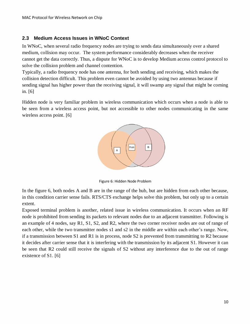
Hidden node is very familiar problem in wireless communication which occurs when a node is able to
be seen from a wireless access point, but not accessible to other nodes communicating in the same
wireless access point. [6]
Figure 6: Hidden Node Problem
In the figure 6, both nodes A and B are in the range of the hub, but are hidden from each other because,
in this condition carrier sense fails. RTS/CTS exchange helps solve this problem, but only up to a certain
extent.
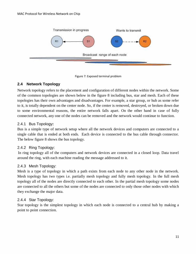
Exposed terminal problem is another, related issue in wireless communication. It occurs when an RF
node is prohibited from sending its packets to relevant nodes due to an adjacent transmitter. Following is
an example of 4 nodes, say R1, S1, S2, and R2, where the two corner receiver nodes are out of range of
each other, while the two transmitter nodes s1 and s2 in the middle are within each other’s range. Now,
if a transmission between S1 and R1 is in process, node S2 is prevented from transmitting to R2 because
it decides after carrier sense that it is interfering with the transmission by its adjacent S1. However it can
be seen that R2 could still receive the signals of S2 without any interference due to the out of range
existence of S1. [6]
Page 22
MAC Protocol for Wireless Network on Chip
11
Figure 7: Exposed terminal problem
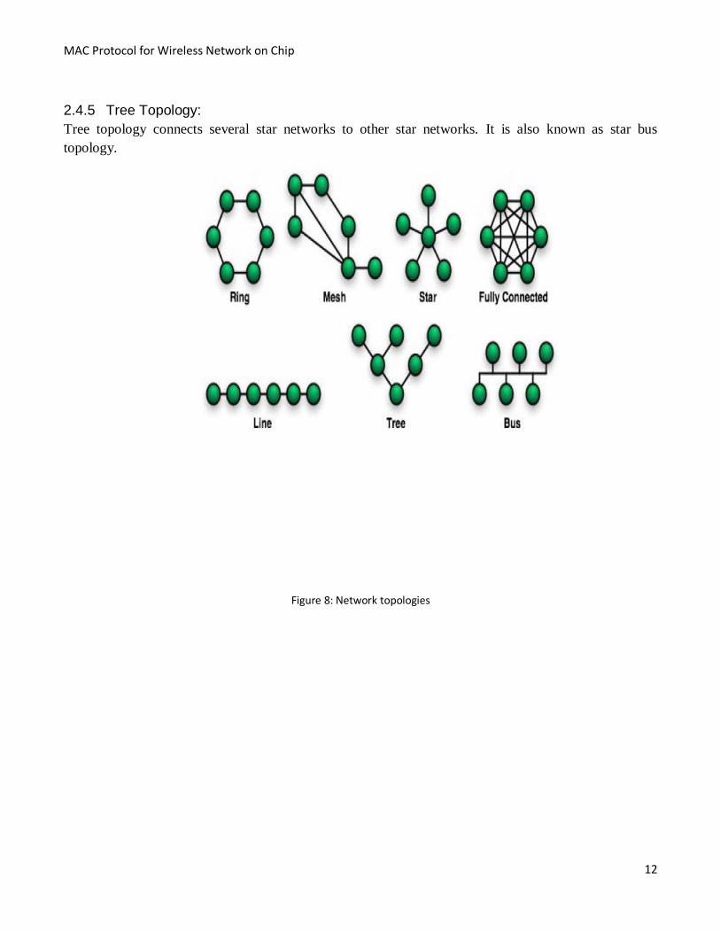
2.4 Network Topology
Network topology refers to the placement and configuration of different nodes within the network. Some
of the common topologies are shown below in the figure 8 including bus, star and mesh. Each of these
topologies has their own advantages and disadvantages. For example, a star group, or hub as some refer
to it, is totally dependent on the center node. So, if the center is removed, destroyed, or broken down due
to some environmental reasons, the entire network falls apart. On the other hand in case of fully
connected network, any one of the nodes can be removed and the network would continue to function.
2.4.1 Bus Topology:
Bus is a simple type of network setup where all the network devices and computers are connected to a
single cable that is ended at both ends. Each device is connected to the bus cable through connector.
The below figure 8 shows the bus topology.
2.4.2 Ring Topology:
In ring topology all of the computers and network devices are connected in a closed loop. Data travel
around the ring, with each machine reading the message addressed to it.
2.4.3 Mesh Topology:
Mesh is a type of topology in which a path exists from each node to any other node in the network.
Mesh topology has two types i.e. partially mesh topology and fully mesh topology. In the full mesh
topology all of the nodes are directly connected to each other. In the partial mesh topology some nodes
are connected to all the others but some of the nodes are connected to only those other nodes with which
they exchange the major data.
2.4.4 Star Topology:
Star topology is the simplest topology in which each node is connected to a central hub by making a
point to point connection.
Page 23
MAC Protocol for Wireless Network on Chip
12
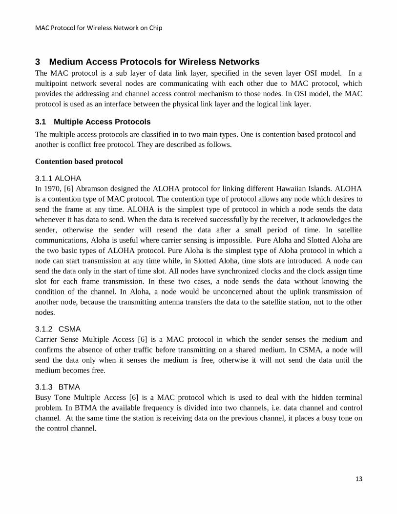
2.4.5 Tree Topology:
Tree topology connects several star networks to other star networks. It is also known as star bus
topology.
Figure 8: Network topologies
Page 24
MAC Protocol for Wireless Network on Chip
13
3 Medium Access Protocols for Wireless Networks
The MAC protocol is a sub layer of data link layer, specified in the seven layer OSI model. In a
multipoint network several nodes are communicating with each other due to MAC protocol, which
provides the addressing and channel access control mechanism to those nodes. In OSI model, the MAC
protocol is used as an interface between the physical link layer and the logical link layer.
3.1 Multiple Access Protocols
The multiple access protocols are classified in to two main types. One is contention based protocol and
another is conflict free protocol. They are described as follows.
Contention based protocol
3.1.1 ALOHA
In 1970, [6] Abramson designed the ALOHA protocol for linking different Hawaiian Islands. ALOHA
is a contention type of MAC protocol. The contention type of protocol allows any node which desires to
send the frame at any time. ALOHA is the simplest type of protocol in which a node sends the data
whenever it has data to send. When the data is received successfully by the receiver, it acknowledges the
sender, otherwise the sender will resend the data after a small period of time. In satellite
communications, Aloha is useful where carrier sensing is impossible. Pure Aloha and Slotted Aloha are
the two basic types of ALOHA protocol. Pure Aloha is the simplest type of Aloha protocol in which a
node can start transmission at any time while, in Slotted Aloha, time slots are introduced. A node can
send the data only in the start of time slot. All nodes have synchronized clocks and the clock assign time
slot for each frame transmission. In these two cases, a node sends the data without knowing the
condition of the channel. In Aloha, a node would be unconcerned about the uplink transmission of
another node, because the transmitting antenna transfers the data to the satellite station, not to the other
nodes.
3.1.2 CSMA
Carrier Sense Multiple Access [6] is a MAC protocol in which the sender senses the medium and
confirms the absence of other traffic before transmitting on a shared medium. In CSMA, a node will
send the data only when it senses the medium is free, otherwise it will not send the data until the
medium becomes free.
3.1.3 BTMA
Busy Tone Multiple Access [6] is a MAC protocol which is used to deal with the hidden terminal
problem. In BTMA the available frequency is divided into two channels, i.e. data channel and control
channel. At the same time the station is receiving data on the previous channel, it places a busy tone on
the control channel.
Page 25
MAC Protocol for Wireless Network on Chip
14
3.1.4 Carrier Sense Multiple Access/Collision Avoidance (CSMA/CA)
CSMA/CA [18] shared medium access method is a direct extension of CSMA which enables multiple
users to share the same physical medium and avoid collisions. Incorporation of collision avoidance
makes it suitable for wireless networks. Network nodes with CSMA/CA measure the channel power
before transmitting to decide whether the channel is free to transmit data or not. Usually, a threshold
power is set up for comparison with the channel’s power and, if the channel’s power is greater than the
threshold power, the sender node waits for a random back-off period before transmitting again,
otherwise it starts transmitting data. Sometimes the channel power increases then the threshold power
due to interference which avoids transmission even though channel is free.
Request to Send (RTS) packet by sender and Clear to Send (CTS) packet by receiver is passed to alert
remaining nodes within range of sender, receiver to not transmit for the period of main transmission. Its
implementation partially solves common problems of wireless communication like hidden node and
exposed terminal.
Sending node senses the status of the channel, whether it is busy or free, by Clear Channel Assessment
(CCA) procedure.
This CCA procedure can be carried out in three different ways as described below:
1. Medium is assumed busy if the measured power level (Received Signal Strength Indication,
(RSSI) is higher than a prefixed threshold.
2. Medium is assumed busy if at least one signal with the modulation and spreading characteristics
of 802.15.4 is detected.
3. Medium is assumed busy if both the above assumptions are detected.[22]
3.2 Slotted ALOHA
Unlike pure ALOHA where, whenever a node has to send data, it starts sending and if it collides it
retransmits, slotted ALOHA [18] provides discrete timeslots and enhances the maximum throughput
through less probability of collisions. Thus, it is an improvement upon the pure ALOHA medium access
scheme. A node is able to send only at the start of a timeslot, and thus collisions are reduced. With this
scheme, transmission-attempts within 1 frame-time are needed to be considered and not 2 consecutive
frame-times, because collisions can only occur during each timeslot.
3.3 Reservation ALOHA (R-ALOHA)
Reservation ALOHA [18] is like slotted ALOHA but incorporates contention based reservation schema
to improve the overall communication efficiency. In the reservation ALOHA scheme, the slot is
temporarily considered "owned" by the station that just successfully used it. Once the station is finished
with its transmission, it simply stops sending data. Here, idle slots are considered to be available to all
stations that can then implicitly reserve/utilize the slot on a contention basis.
Page 26
MAC Protocol for Wireless Network on Chip
15
Conflict Free Protocols
3.4 Fixed Assignment Protocols
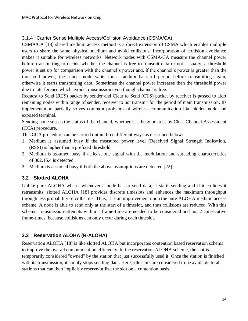
3.4.1 TDMA
TDMA is a channel access method [11] used for shared method for shared medium network. It can
accommodate multiple users in a same frequency channel by dividing the frequency channel usage in
time slots. In TDMA method the time axis is divided into a number of time slots, which are pre-assigned
to different users. Each user has right to transmit freely during that slot assigned to it and all the system
resources are devoted to it during that slot. Every such period is known as frame or cycle. In basic
TDMA each user has exactly one slot in every frame. The more general TDMA schemes in which more
slots are assigned to one user within a frame is referred to as generalized TDMA.
For proper coordination of users in TDMA the users must be synchronized so that each user knows
exactly when and for how long he can transmit.
Figure 9: TDMA
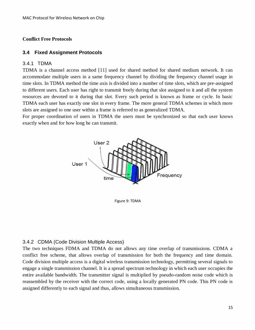
3.4.2 CDMA (Code Division Multiple Access)
The two techniques FDMA and TDMA do not allows any time overlap of transmissions. CDMA a
conflict free scheme, that allows overlap of transmission for both the frequency and time domain.
Code division multiple access is a digital wireless transmission technology, permitting several signals to
engage a single transmission channel. It is a spread spectrum technology in which each user occupies the
entire available bandwidth. The transmitter signal is multiplied by pseudo-random noise code which is
reassembled by the receiver with the correct code, using a locally generated PN code. This PN code is
assigned differently to each signal and thus, allows simultaneous transmission.
Page 27
MAC Protocol for Wireless Network on Chip
16
.
Figure 10: CDMA
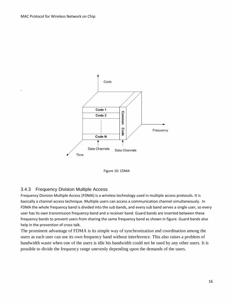
3.4.3 Frequency Division Multiple Access
Frequency Division Multiple Access (FDMA) is a wireless technology used in multiple access protocols. It is
basically a channel access technique. Multiple users can access a communication channel simultaneously. In
FDMA the whole frequency band is divided into the sub bands, and every sub band serves a single user, so every
user has its own transmission frequency band and a receiver band. Guard bands are inserted between these
frequency bands to prevent users from sharing the same frequency band as shown in figure. Guard bands also
help in the prevention of cross talk.
The prominent advantage of FDMA is its simple way of synchronization and coordination among the
users as each user can use its own frequency band without interference. This also raises a problem of
bandwidth waste when one of the users is idle his bandwidth could not be used by any other users. It is
possible to divide the frequency range unevenly depending upon the demands of the users.
Page 28
MAC Protocol for Wireless Network on Chip
17
FDMA is not a flexible solution for adding new users to the network; it requires equipment modification
like additional filter units for every other user. FDMA is a full duplex communication system; hence the
users can receive and transmit simultaneously
Figure 111: Sub bands and Guard Channels in FDMA
3.4.4 MCCDMA
Code division multiple access (CDMA) is a technique which uses multiplexing to allow multiple users
to access a shared medium asynchronously by modulating and spreading their information with pre-
assigned codes. To perform high data rate transmissions in radio communication, multicarrier
modulation techniques, often called Orthogonal Frequency Division Multiplexing (OFDMA) is being
used.[14]
3.4.4.1 OFDMA schemes
The basic principle of OFDMA is to split high rate DataStream into a number of lower rate streams that
are transmitted simultaneously over a number of sub carriers, however, along with this, it has
disadvantages, such as complex subcarrier synchronization and higher sensitivity to frequency offset,
which combine with the result the that it is composed of lots of overlapping power spectra subcarriers. It
also leads to multicarrier CDMA, although the combination of CDMA with OFDMA signaling is
advantageous because it lowers the symbol rate for each subcarrier to achiever longer symbol duration
which makes synchronization of transmission easier. [15]
3.4.5 Frequency domain spreading with multicarrier modulation (MC-CDMA)
In the MC-CDMA scheme, a transmitter spreads the data stream over subcarriers with the given
spreading code in the frequency domain. On the receiver side, Hadamard Walsh codes can be used as an
optimum orthogonal set, which provides support for auto-correlation characteristic of the spreading
codes. To increase the robustness of frequency selective fading, a proper number of subcarriers and
guard intervals between them are very important. With a frequency selective fast fading channel for
multipath, an optimal value exists to minimize bit error rate in the number of subcarriers and guard
intervals.
Page 29
MAC Protocol for Wireless Network on Chip
18
The MC-CDMA receiver combines the received signal in the sense that, in frequency domain, the
receiver is able to employ all the received energy of the signal scattered in frequency domain. This is the
main advantage of MC-CDMA over other schemes.
Page 30
MAC Protocol for Wireless Network on Chip
19
4 Architectures for WNoC
WNoC architecture, in the sense of interconnects, can be broadly seen on 2 levels as follows:
1. IP Core Level
This level describes the interconnection of on-chip ip cores. The ip cores are the building blocks of
network on chip and the communication between them will be done through wired and wireless
medium. To provide wireless medium for the communication among these ip cores, the RF nodes are
dispersed on the chip.
2. RF Node Level
This level of interconnects is for RF nodes found on the chip. Several RF nodes equipped with
transceivers and tiny antennas are dispersed on the chip to provide wireless communication among
different ip cores.
4.1 Adjacent RF nodes wired and wireless interconnection
Architecture:
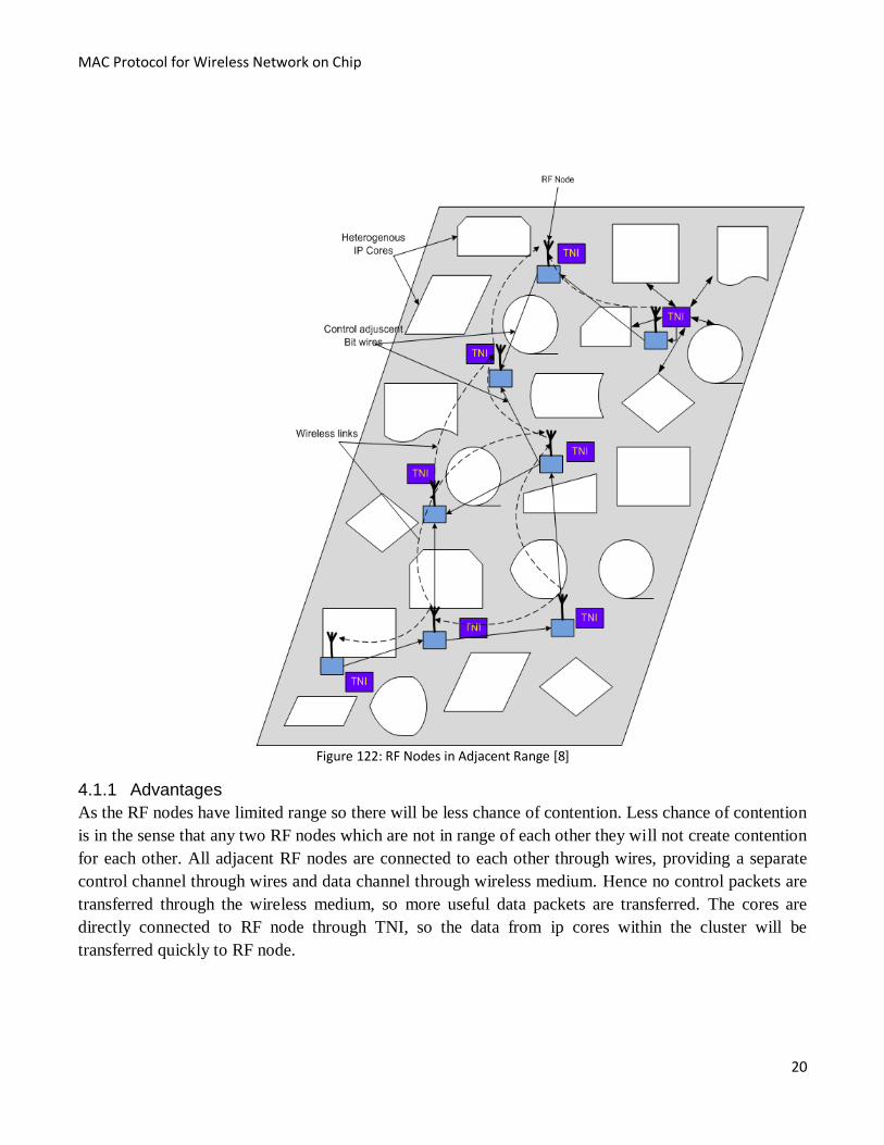
In [8] the authors proposed the design and synthesis of a synchronous and distributed MAC protocol for
WNoC. We review their work in our report in order to provide a background for our work. The below
figure 14 shows the system architecture for WNoC, mainly focused on RF infrastructure. Several RF
nodes equipped with transceivers and antennas are dispersed on chip making a multi-hop wireless
network. The ip cores access the RF nodes via TNI (Transparent Network Interface) and the messages
are reached to the destination through multi-hops across the network. The ip cores are clustered on the
chip in order to minimize the routing cost and to stable the communication workload consequently.
These ip cores within the cluster are hardwired to RF node via TNI and share it for data communication.
All RF nodes are of limited range and they are connected to each other through adjacent RF nodes by
wires (within the wireless transmission range). These RF nodes are connected through both wired and
wireless medium. The wired medium is used for control logic and wireless medium for transmition of
data. The control logic through wires is for the purpose to access the channel, and as soon the channel is
accessed then data is being transferred through wireless. Each RF node has a set of n control lines
(Rx/Tx) connected to its n neighbors. Each pair of control lines consists of a single bit input
(Rx[i])/output (Tx[i]) line for handshaking between a RF node and its ith neighbor. Based on this hybrid
interconnection infrastructure, the multiple access controlling is performed on these control wires and
data are transmitted through network wirelessly.
This architecture has separate wired controlling channel and wireless data transmission channel which
bring a number of benefits. First of all, we may keep away the expensive data synchronization and only
the control signals are need to be synchronized. Second, the control logic can be simplified to bit
operations and thus faster and simpler to implement. Third one is that no control packets are sent
through the wireless media, so it means we can transmit more useful data through wireless medium.
Page 31
MAC Protocol for Wireless Network on Chip
20
Figure 122: RF Nodes in Adjacent Range [8]
4.1.1 Advantages
As the RF nodes have limited range so there will be less chance of contention. Less chance of contention
is in the sense that any two RF nodes which are not in range of each other they will not create contention
for each other. All adjacent RF nodes are connected to each other through wires, providing a separate
control channel through wires and data channel through wireless medium. Hence no control packets are
transferred through the wireless medium, so more useful data packets are transferred. The cores are
directly connected to RF node through TNI, so the data from ip cores within the cluster will be
transferred quickly to RF node.
Page 32
MAC Protocol for Wireless Network on Chip
21
4.1.2 Disadvantages
All RF nodes are not in range of each other so the far away RF nodes will receive the data with a longer
delay, because the transmission will be done through the adjacent RF nodes. The basic architecture of ip
cores is not scalable because all of the cores within the cluster are directly wired connected to RF node
through TNI. Hence, we cannot reduce or expand the size of cluster and in order to do this we would
need hardwiring again.
In above architecture [8], it has been observed that it does not provide specific power range of RF nodes.
This is assuming that all RF nodes have a limited range and they communicate with each other through
adjacent RF nodes, which is beyond the realistic nature of radio communication. Therefore, we did not
continue our work with this architecture.
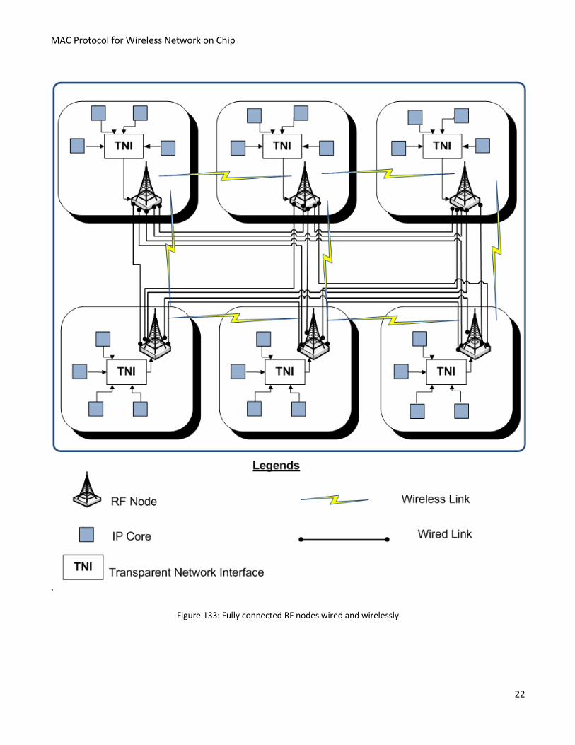
4.2 Fully connected RF nodes wired and wirelessly
Architecture
This model is a direct variation of the previous one. Here all RF nodes are directly connected to each
other through both wires and wirelessly. As shown in figure 15, the ip cores are properly clustered in
order to minimize the routing cost and to stable the communication workload accordingly. The ip cores
in a cluster are hardwired to RF node via TNI. All these ip cores within the cluster are connected to each
other through wires via TNI, while outside the cluster they are not connected to each other through
wires. The ip cores outside the cluster will communicate to each other through wireless medium. Several
RF nodes are dispersed across the chip. Each cluster containing ip cores are equipped with a RF node.
We suppose all these RF nodes are in wireless range of each other. Moreover all these RF nodes are
directly connected to each other through wires as well. The control logic (channel access) is achieved
through wires and data is transferred through wireless medium. Each RF node has a set of n control lines
(Rx/Tx) connected to its n neighbors. Each pair of control lines consists of a single bit input
(Rx[i])/output (Tx[i]) line for handshaking between a RF node and its ith neighbor. Based on this hybrid
interconnection infrastructure, the multiple access controlling is performed on these control wires and
data are transmitted through network wirelessly [8].
Here in this architecture we have the same benefit like in the previous one but here all the RF nodes are
directly connected to each other through wires and wirelessly. Moreover all RF nodes are supposed to be
in range of each other (within the wireless range). Hence by adding those features the communication
will become more effectively. As all RF nodes can easily communicate with each other.
Page 33
MAC Protocol for Wireless Network on Chip
22
.
Figure 133: Fully connected RF nodes wired and wirelessly
Page 34
MAC Protocol for Wireless Network on Chip
23
4.2.1 Advantages
As all RF nodes are directly connected to each other through wires, so the multiple access control is
performed by wires and data is transferred through the network wirelessly. Each RF node has a set of n
control lines (Rx/Tx) connected to its n neighbors. Each pair of control lines consists of a single bit input
(Rx[i])/output (Tx[i]) line for handshaking between a RF node and its ith neighbor. Based on this hybrid
interconnection infrastructure, the multiple access controlling is performed on these control wires and
data are transmitted through network wirelessly [8].
4.2.2 Disadvantages
The basic architecture of ip cores is not scalable because all of the cores within the cluster are directly
wired connected to RF node through TNI. Hence we cannot reduce or expand the size of cluster and for
doing this we will be in need of hardwiring again. Extra wiring for full connections could be an
unaffordable overhead on the chip.
This architecture is the modification of previous one. Instead of radio range limited to adjacent nodes, it
is supposed that all RF nodes will be in range of each other and they will be directly connected through
wires as well for only control logic (channel access). This architecture has scalability issue because it
required more wiring and mitigate against the basic feature of wireless communication. Thus it cannot
be continued in our case.
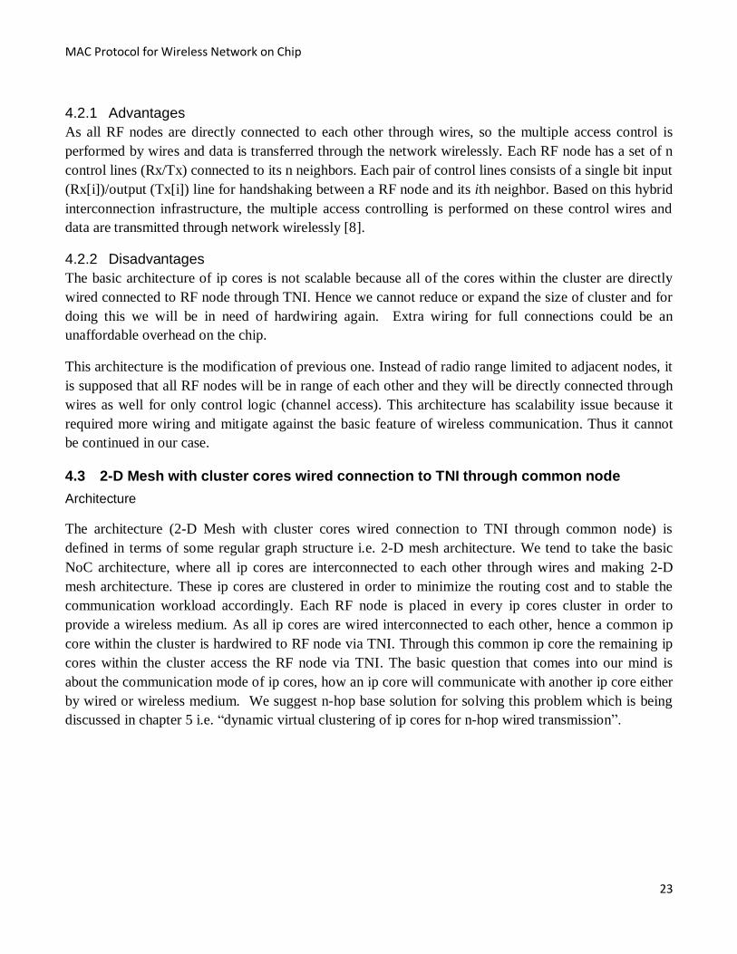
4.3 2-D Mesh with cluster cores wired connection to TNI through common node
Architecture
The architecture (2-D Mesh with cluster cores wired connection to TNI through common node) is
defined in terms of some regular graph structure i.e. 2-D mesh architecture. We tend to take the basic
NoC architecture, where all ip cores are interconnected to each other through wires and making 2-D
mesh architecture. These ip cores are clustered in order to minimize the routing cost and to stable the
communication workload accordingly. Each RF node is placed in every ip cores cluster in order to
provide a wireless medium. As all ip cores are wired interconnected to each other, hence a common ip
core within the cluster is hardwired to RF node via TNI. Through this common ip core the remaining ip
cores within the cluster access the RF node via TNI. The basic question that comes into our mind is
about the communication mode of ip cores, how an ip core will communicate with another ip core either
by wired or wireless medium. We suggest n-hop base solution for solving this problem which is being
discussed in chapter 5 i.e. “dynamic virtual clustering of ip cores for n-hop wired transmission”.
Page 35
MAC Protocol for Wireless Network on Chip
24
Figure 144: 2-D Mesh Architecture with cluster cores connected to TNI through common node
This 2-D mesh architecture brings several benefits in the ip core level. First of all it will remain in the
basic NoC architecture shape but with a slight difference by inserting the RF nodes in different places.
Secondly all ip cores will be connected to each other and they will communicate either by wires or
wirelessly by selecting n-hop base solution. As all ip cores are in 2-D mesh shape so an ip core of one
Page 36
MAC Protocol for Wireless Network on Chip
25
cluster can communicate with the ip core of another cluster through wire as well. They will only
communicate through wireless medium if the ip core is out of n-hop level.
4.3.1 Advantages
The basic architecture of ip cores in this 2-D mesh architecture is scalable because of structure of
cluster. As all ip cores are wired interconnected to each other in the chip and within the cluster they are
connected to RF node by a common ip core. Hence we can easily reduce and expand the size of cluster.
Further within the cluster only a common ip core is directly hardwired to RF node and the remaining ip
cores access the RF node through this common ip core. So this will reduce the number of wires in the
chip.
4.3.2 Disadvantages
As the ip Cores within the cluster are not directly connected to RF node, they are only connected
through common core through TNI, so the rest of the cores within the cluster will take time to send data
to the RF node. Hence, the remaining cores within the cluster will send data to RF node through adjacent
nodes and in such a way that it will take time to reach to the destination.
As discussed above, the main disadvantage of this architecture is that ip cores are connected to RF node
through a common core, and hence, the rest of ip cores will get delay during communication. That is
why we did not continue with this architecture; it was because we wanted to improve communication
between the ip cores as much as possible.
4.4 Proposed Architecture (2-D Mesh Architecture with cluster cores directly wired
connected to TNI)
Architecture
This is also our proposed architecture and it is basically a modification of our previous proposed
Architecture (2-D mesh architecture with cluster cores connected to TNI through common node). The
basic architecture is the same as in the (2-D Mesh with cluster cores wired connection to TNI through
common node) architecture but with a little change within the cluster. The ip cores within the cluster are
directly hardwired to RF node via TNI. The purpose of doing this is just to remove the time delay of ip
cores when accessing the RF node via TNI. All ip cores are interconnected to each other through wires,
and making 2-D mesh architecture.
These ip cores are clustered in order to minimize the routing cost and communication workload
accordingly. Each RF node is installed in every cluster of ip cores. The ip core will decide (same like in
the previous architecture of 2-D mesh) to transfer the data through wired or wireless medium by n-hop
base solution. The n-hop base solution is discussed in chapter 5 i.e. “dynamic virtual clustering of ip
cores for n-hop wired transmission”. The MAC protocol for WNoC is discussed in the coming chapter 6
on the basis of this proposed architecture.
Page 37
MAC Protocol for Wireless Network on Chip
26
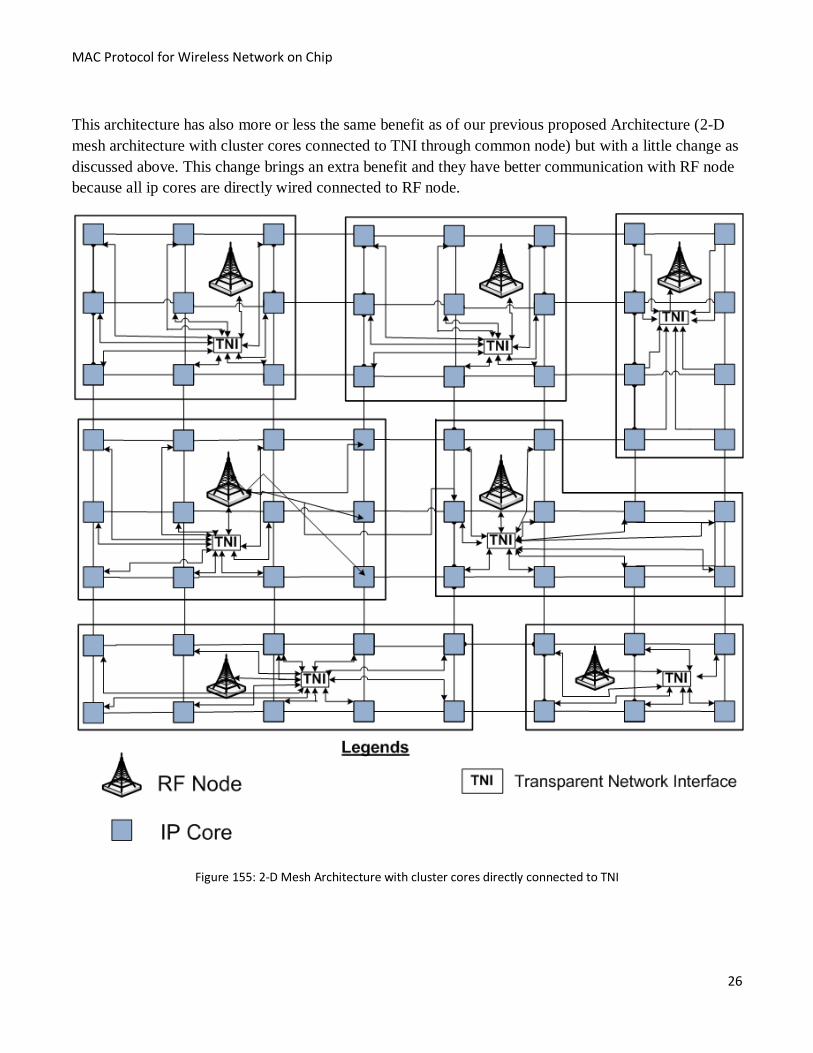
This architecture has also more or less the same benefit as of our previous proposed Architecture (2-D
mesh architecture with cluster cores connected to TNI through common node) but with a little change as
discussed above. This change brings an extra benefit and they have better communication with RF node
because all ip cores are directly wired connected to RF node.
Figure 155: 2-D Mesh Architecture with cluster cores directly connected to TNI
Page 38
MAC Protocol for Wireless Network on Chip
27
4.4.1 Advantages
As the cores are directly connected to RF node through TNI, so the data from ip cores within the cluster
will be transferred quickly to RF node.
4.4.2 Disadvantages
The basic architecture of ip cores is not scalable because all of the cores within the cluster are directly
wired connected to RF node through TNI. Hence, we cannot reduce or expand the size of cluster and for
doing this we will be in need of hardwiring again. Further as ip cores are directly hardwired to RF node
via TNI, so the numbers of wires will increases.
Comparatively, this architecture is suitable for WNoC because all of the ip cores will have better
communication among each other. As all ip cores are interconnected to each other forming 2-D mesh
architecture and ip cores within the cluster are directly hardwired to RF node via TNI. Hence the
communication among ip cores will be faster as compared to the rest of architectures. Therefore, we
finalize this architecture for WNoC Communication Mechanism.
Page 39
MAC Protocol for Wireless Network on Chip
28
5 Proposed Architecture for WNoC
5.1 Proposed Architecture (2-D Mesh Architecture with cluster cores directly wired
connected to TNI)
Architecture
This is also our proposed architecture and it is basically a modification of our previous proposed
Architecture (2-D mesh architecture with cluster cores connected to TNI through common node). The
basic architecture is the same as in the (2-D Mesh with cluster cores wired connection to TNI through
common node) architecture but with a little change within the cluster. The ip cores within the cluster are
directly hardwired to RF node via TNI. The purpose of doing this is just to remove the time delay of ip
cores when accessing the RF node via TNI. All ip cores are interconnected to each other through wires,
and making 2-D mesh architecture. These ip cores are clustered in order to minimize the routing cost
and communication workload accordingly. Each RF node is installed in every cluster of ip cores. The ip
core will decide (same like in the previous architecture of 2-D mesh) to transfer the data through wired
or wireless medium by n-hop base solution. The n-hop base solution is discussed in chapter 5 i.e.
“dynamic virtual clustering of ip cores for n-hop wired transmission”. The MAC protocol for WNoC is
discussed in the coming chapter 6 on the basis of this proposed architecture.
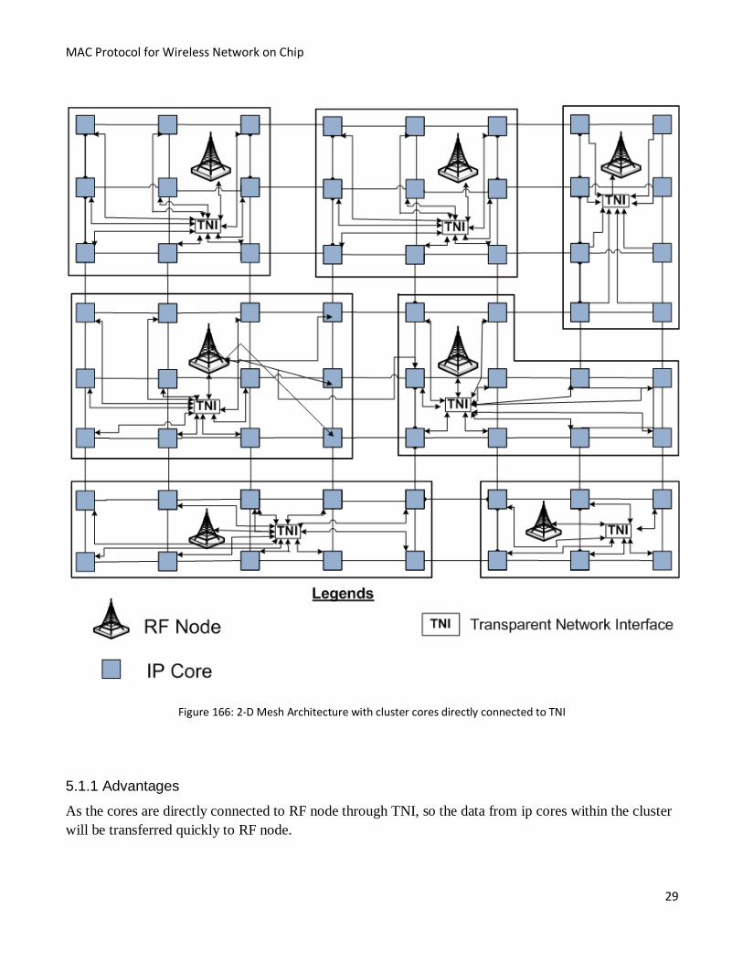
This architecture has also more or less the same benefit as of our previous proposed Architecture (2-D
mesh architecture with cluster cores connected to TNI through common node) but with a little change as
discussed above. This change brings an extra benefit and they have better communication with RF node
because all ip cores are directly wired connected to RF node.
Page 40
MAC Protocol for Wireless Network on Chip
29
Figure 166: 2-D Mesh Architecture with cluster cores directly connected to TNI
5.1.1 Advantages
As the cores are directly connected to RF node through TNI, so the data from ip cores within the cluster
will be transferred quickly to RF node.
Page 41
MAC Protocol for Wireless Network on Chip
30
5.1.2 Disadvantages
The basic architecture of ip cores is not scalable because all of the cores within the cluster are directly
wired connected to RF node through TNI. Hence, we cannot reduce or expand the size of cluster and for
doing this we will be in need of hardwiring again. Further the as ip cores are directly hardwired to RF
node via TNI, so the number of wires will increases.
Comparatively, this architecture is suitable for WNoC because all of the ip cores will have better
communication among each other. As all ip cores are interconnected to each other forming 2-D mesh
architecture and ip cores within the cluster are directly hardwired to RF node via TNI. Hence the
communication among ip cores will be faster as compared to the rest of architectures. Therefore, we
finalize this architecture for WNoC Communication Mechanism.
5.2 Wired Communication of ip cores for proposed architecture
5.2.1 Parameters and approach for wired communication
All ip cores are hardwired to each other in the proposed architecture forming 2-D mesh architecture, so
we suggest unicast routing. In unicast routing packets have a unique destination while in multicast
routing packets have multiple destinations. The unicast routing approach seems to be more practical due
to the existence of point to point communication links among several ip cores in chip.
Routing algorithm can also be defined based on their implementation: Lookup Table Routing Algorithm
and Finite State Machine: instead of finite state machine (FSM) based routing algorithms, a lookup table
based algorithm is more suitable because of its re-configurability for routing entries. FSM based
algorithm is complicated as compared to lookup table routing algorithm. In look up table routing the
processing time can be reduced because regaining a value from memory is often faster than enduring an
expensive computation process. Hence in lookup table there is no need of computation during run time.
The routing algorithms may further divided base on the adaptability. Deterministic routing is more
suitable due to the fact that it follows a deterministic path on the network. While adaptive routing
requires more information about the network to keep away from crowded paths in the network.
Switching techniques can be classified on the basis of network characteristics. Circuit switching
technique reserves the physical path before passing data packets, while packet switching technique did
not reserve the complete path. To avoid the whole path from reserves, the packet switching technique is
suitable for the proposed architecture of wired communication.
5.2.2 N-hope wired communication between IP cores
Recently, a lot of effort has been put on wired communication between the IP cores in Network on Chip
interconnects. In NoC architecture, each node is connected to its router through its network interface. In
case of packet based transmission, network interface packetizes the data and transmits towards its router
where it is forwarded towards destination according to the routing information.
Page 42
MAC Protocol for Wireless Network on Chip
31
Wired communication among IP cores in this proposed architecture for WNoC is a variation of the
normal wired communication among IP cores of NoC. In this approach, a predetermined number of hops
are used to perform communication, i.e. wired transmission is limited to N number of hop counts. The
value of N is determined by the scalability of IP cores on the chip.
5.2.3 Static Clustering of IP cores for RF Nodes
IP cores on the chip are divided into regions called clusters. In a cluster we have n number of IP cores, a
Transparent Network Interface (TNI) and a RF node. The IP cores are properly clustered in order to
minimize the routing cost and to stable the communication workload consequently. The IP cores in a
cluster are hardwired to RF node via TNI in order to access the RF node.
5.2.4 Dynamic virtual clustering of IP cores for n-hop wired transmission
In this varied form of wired communication among IP cores, each time a IP core needs to send data to a
destination IP core, it is checked by the adjacent IP core to find the destination. If the destination node is
approached within the predefined n hop counts, data is transmitted through wires. On the other hand, if
the destination is out of the n hope count, then it is transferred to the RF node via TNI to be transferred
wirelessly. In this way, each time an IP core needs to send data; it creates a virtual cluster of n-hop
distance around it, through which it is determined whether it should be transmitted wirelessly or through
wires. In this way, wired transmission is independent of the static clusters, i.e. core in a cluster can send
data through wires to its adjacent cores in another cluster if it is under the n-hop count.
5.3 Wireless Communication
5.3.1 Analyzed Requirements of MAC for our proposed architecture of WNoC
Simultaneous multiple asynchronous transmissions over shared media
Decentralized, non-managed(without access point) ad hoc nature of network
ALL RF Nodes are in each other’s range
Free space signal broadcasting instead of guided or directional.
5.3.2 Issues to be considered for basic architecture of WNoChip:
Synchronization for decentralized environment (can be through control packets)
Contention/Congestion resolution for concurrent transmissions
Hardware size limitations both for antenna and circuit (future nanometer CMOS technology with
terabyte data rate)
Complexity limitation for on chip fabrication
Scalability of ip cores and RF nodes
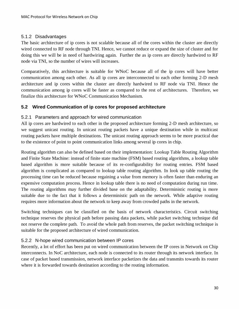
Below is the graph which shows the relation of antenna size with respect to the CMOS technology used.
With CMOS technology of 90 nm it is possible to place an antenna of size 350 nm on a chip.
Page 43
MAC Protocol for Wireless Network on Chip
32
Figure 177: Relation of antenna size and CMOS technology
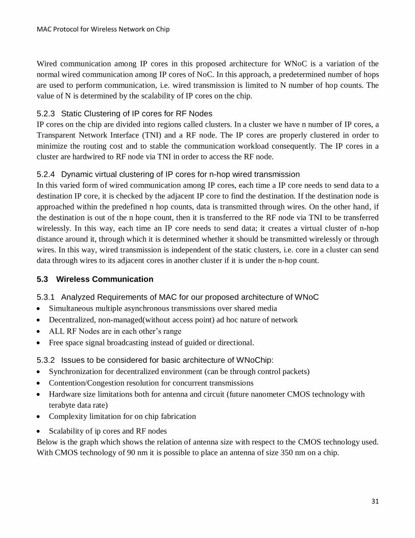
Figure 18: Relation of number of channel and CMOS technology
The above graph shows that the number of channels depends on the CMOS technolgy that is being
used.For example, in case of 22nm cmos technology, it is possible to have more channels comparatively.
Page 44
MAC Protocol for Wireless Network on Chip
33
6 Channel Access Mechanisms in WNoC
6.1 Implementation of WNoC Using TDMA
The on-chip network communication through wireless medium is designed to transmit data with low
latencies and high throughput using TDMA.
We discussed the TDMA from [18] for WNoC in our proposed architecture. Time division multiple
access is a channel access mechanism, where multiple nodes share a single frequency for a certain
amount of time. Each node gets the channel exclusively for a certain time slot and gives it up while all
the other nodes take their turn.
Assumption
We assumed 256 RF nodes for our proposed WNoC architecture but only 16 RF nodes will send data
during each contention period. The 256 time slots are assumed, each for 0.1 ns duration and 8 bit long.
A central clock is assumed but it will not be discussed here.
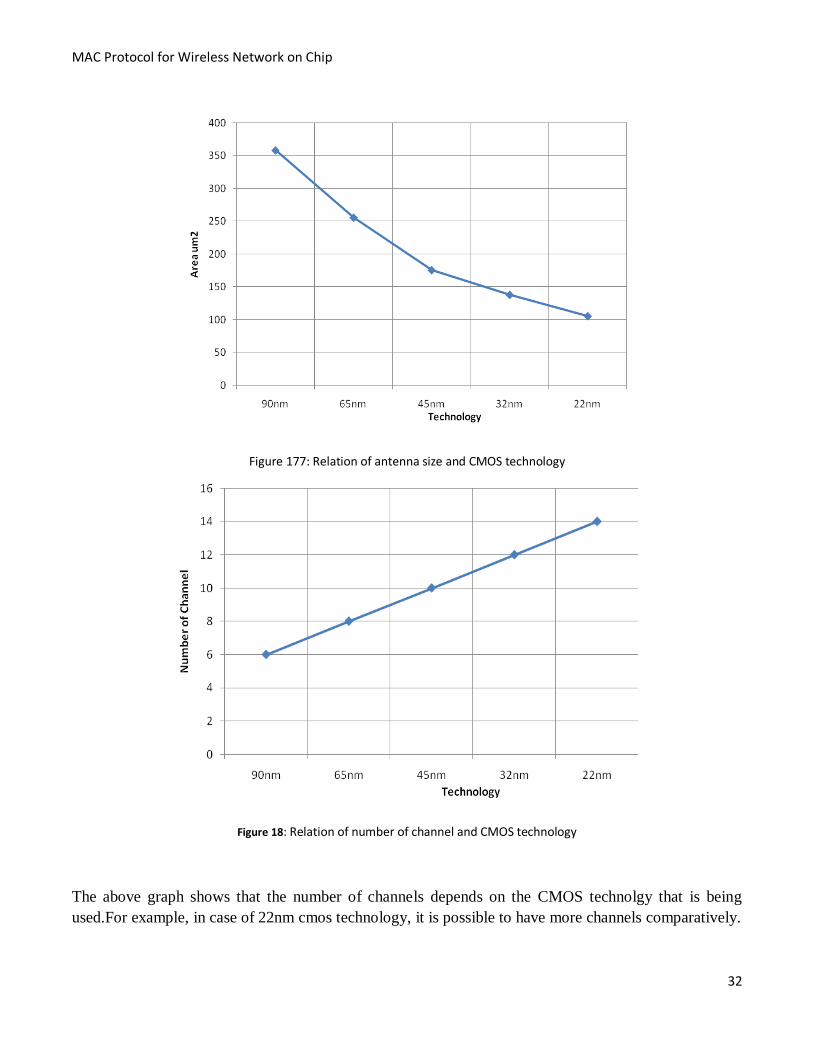
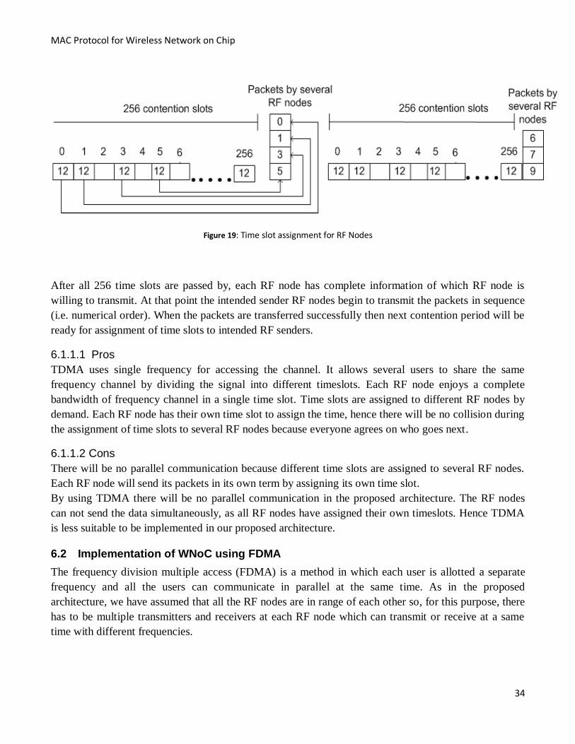
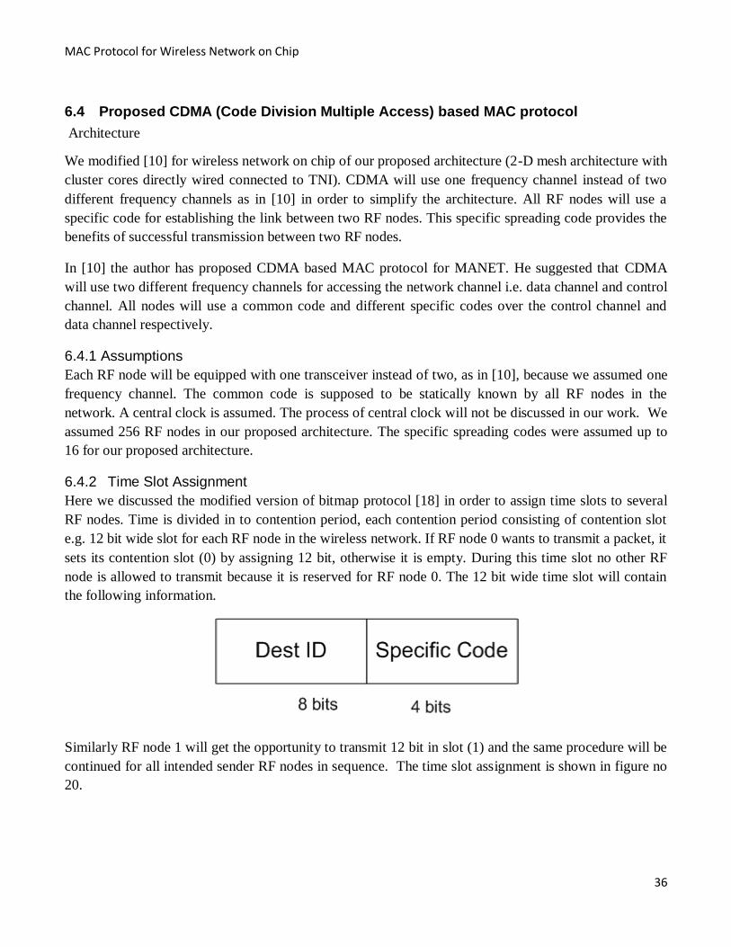
6.1.1 Basic TDMA Mechanism
Time is divided in to contention period, each contention period consisting of contention slot e.g. 8 bit
wide slot for each RF node in the wireless network. If RF node 0 wants to transmit a packet, it sets its
contention slot (0) by assigning 8 bit, otherwise it is empty. During this time slot no other RF node is
allowed to transmit because it is reserved for RF node 0. The 8 bit wide time slot will contain the
following information.
Similarly RF node 1 will get the opportunity to transmit 8 bit in its own slot 1, but only if it has a frame
queued. In general RF node j may announce that it has a frame to send by inserting 8 bit in its own slot
j. After all n slots have passed by, each RF node has complete knowledge of which RF node wish to
transmit. At that point, they begin transmitting in numerical order. The following figure 21 shows the
time slot allocation.
Page 45
MAC Protocol for Wireless Network on Chip
34
Figure 19: Time slot assignment for RF Nodes
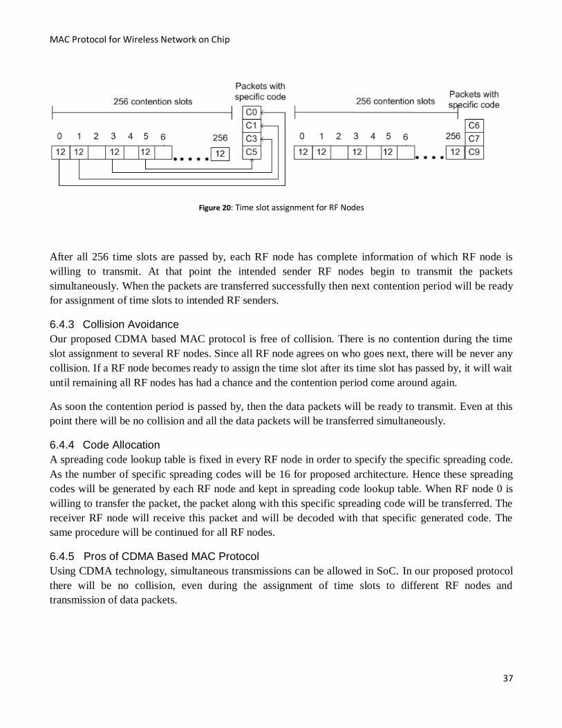
After all 256 time slots are passed by, each RF node has complete information of which RF node is
willing to transmit. At that point the intended sender RF nodes begin to transmit the packets in sequence
(i.e. numerical order). When the packets are transferred successfully then next contention period will be
ready for assignment of time slots to intended RF senders.
6.1.1.1 Pros
TDMA uses single frequency for accessing the channel. It allows several users to share the same
frequency channel by dividing the signal into different timeslots. Each RF node enjoys a complete
bandwidth of frequency channel in a single time slot. Time slots are assigned to different RF nodes by
demand. Each RF node has their own time slot to assign the time, hence there will be no collision during
the assignment of time slots to several RF nodes because everyone agrees on who goes next.
6.1.1.2 Cons
There will be no parallel communication because different time slots are assigned to several RF nodes.
Each RF node will send its packets in its own term by assigning its own time slot.
By using TDMA there will be no parallel communication in the proposed architecture. The RF nodes
can not send the data simultaneously, as all RF nodes have assigned their own timeslots. Hence TDMA
is less suitable to be implemented in our proposed architecture.
6.2 Implementation of WNoC using FDMA
The frequency division multiple access (FDMA) is a method in which each user is allotted a separate
frequency and all the users can communicate in parallel at the same time. As in the proposed
architecture, we have assumed that all the RF nodes are in range of each other so, for this purpose, there
has to be multiple transmitters and receivers at each RF node which can transmit or receive at a same
time with different frequencies.
Page 46
MAC Protocol for Wireless Network on Chip
35
Assumption
We assumed 16 RF nodes for our proposed WNoC architecture regarding FDMA scheme. Each RF
nodes is assumed to have 16 receivers and same number of transceivers.
6.3 Basic FDMA scheme
In [13] Hybrid TDM-FDM scheme is used but, according to the architecture, only adjacent nodes can
communicate. In the proposed architecture, each and every node is in range of each other so we will take
only FDM specifications. The total number of frequencies deployed is 16 so it means that 16
communications can be possible simultaneously. Distinct frequency can be assigned to each pair
(transmitter and receiver) so that each transmitter and receiver should be able to modulate and
demodulate every distinct frequency. This means that there will be 16 transmitters and 16 receivers at
each RF node, and each RF node should also have CNT antennas of different lengths .Thus, from the
poll of these different frequencies, frequencies can be assigned to multiple wireless links in the WNoC.
As all RF nodes are in range of each other and each RF node have multiple receivers and transceivers
with distinct frequencies. It means that all RF nodes can transmit data simultaneously.
6.3.1 Pros
All RF nodes can communicate simultaneously. Each communication pair can use the channel as long as
it wants because there is no time slot required. Each RF node will enjoy full channel bandwidth. There
will be no time delay while communicating between different RF nodes.
6.3.2 Cons
All RF nodes are very smaller in size and they have multiple receivers and transceivers, so there will be
more hardware complexities. It is hard to implement so many receivers and transceivers in such a
smaller RF node. As we need a distinct frequency for each communication link it will be difficult to
assign frequencies to newly added RF nodes, thus making it not scalable.After analysis of FDMA
technology, specifically with our proposed architecture, we have established that there are advantages
along with disadvantages. If ip cores are increased, the RF nodes will also have increased. To cater for
the simultaneous transmission of data, hardware complexities need to be compromised as multiple
transceivers are required. So it means that we have to increase the number of transceivers in the already
installed RF nodes.
Hence FDMA, methodology does not support the proposed architecture and to accommodate multiple
frequencies, extra hardware should be placed on chip and as a result, chip density will increase
tremendously.
Page 47
MAC Protocol for Wireless Network on Chip
36
6.4 Proposed CDMA (Code Division Multiple Access) based MAC protocol
Architecture
We modified [10] for wireless network on chip of our proposed architecture (2-D mesh architecture with
cluster cores directly wired connected to TNI). CDMA will use one frequency channel instead of two
different frequency channels as in [10] in order to simplify the architecture. All RF nodes will use a
specific code for establishing the link between two RF nodes. This specific spreading code provides the
benefits of successful transmission between two RF nodes.
In [10] the author has proposed CDMA based MAC protocol for MANET. He suggested that CDMA
will use two different frequency channels for accessing the network channel i.e. data channel and control
channel. All nodes will use a common code and different specific codes over the control channel and
data channel respectively.
6.4.1 Assumptions
Each RF node will be equipped with one transceiver instead of two, as in [10], because we assumed one
frequency channel. The common code is supposed to be statically known by all RF nodes in the
network. A central clock is assumed. The process of central clock will not be discussed in our work. We
assumed 256 RF nodes in our proposed architecture. The specific spreading codes were assumed up to
16 for our proposed architecture.
6.4.2 Time Slot Assignment
Here we discussed the modified version of bitmap protocol [18] in order to assign time slots to several
RF nodes. Time is divided in to contention period, each contention period consisting of contention slot
e.g. 12 bit wide slot for each RF node in the wireless network. If RF node 0 wants to transmit a packet, it
sets its contention slot (0) by assigning 12 bit, otherwise it is empty. During this time slot no other RF
node is allowed to transmit because it is reserved for RF node 0. The 12 bit wide time slot will contain
the following information.
Similarly RF node 1 will get the opportunity to transmit 12 bit in slot (1) and the same procedure will be
continued for all intended sender RF nodes in sequence. The time slot assignment is shown in figure no
20.
Page 48
MAC Protocol for Wireless Network on Chip
37
Figure 20: Time slot assignment for RF Nodes
After all 256 time slots are passed by, each RF node has complete information of which RF node is
willing to transmit. At that point the intended sender RF nodes begin to transmit the packets
simultaneously. When the packets are transferred successfully then next contention period will be ready
for assignment of time slots to intended RF senders.
6.4.3 Collision Avoidance
Our proposed CDMA based MAC protocol is free of collision. There is no contention during the time
slot assignment to several RF nodes. Since all RF node agrees on who goes next, there will be never any
collision. If a RF node becomes ready to assign the time slot after its time slot has passed by, it will wait
until remaining all RF nodes has had a chance and the contention period come around again.
As soon the contention period is passed by, then the data packets will be ready to transmit. Even at this
point there will be no collision and all the data packets will be transferred simultaneously.
6.4.4 Code Allocation
A spreading code lookup table is fixed in every RF node in order to specify the specific spreading code.
As the number of specific spreading codes will be 16 for proposed architecture. Hence these spreading
codes will be generated by each RF node and kept in spreading code lookup table. When RF node 0 is
willing to transfer the packet, the packet along with this specific spreading code will be transferred. The
receiver RF node will receive this packet and will be decoded with that specific generated code. The
same procedure will be continued for all RF nodes.
6.4.5 Pros of CDMA Based MAC Protocol
Using CDMA technology, simultaneous transmissions can be allowed in SoC. In our proposed protocol
there will be no collision, even during the assignment of time slots to different RF nodes and
transmission of data packets.
Page 49
MAC Protocol for Wireless Network on Chip
38
6.4.6 Cons of CDMA Based MAC Protocol
As the number of RF nodes increased, the TDMA based time slot assignment in our approach can be
inefficient in terms of bandwidth and time delay. Due to limited number of codes allowed, only a limited
number of RF nodes can transmit their data packets at a time. Remaining RF nodes will wait for next
contention time periods. The overhead becomes larger in our proposed protocol assuming 256 RF node
and 12 bit wide time slots will give 3072 bit overhead.
Near Far Problem: consider a receiver R and two transmitters, T1 close to the receiver and T2 far away.
If transmitters transmit data simultaneously at equal powers the R will receive more power from the T1.
This makes the T2 more difficult, if not impossible, to understand. One transmission is other's noise the
signal-to-noise ratio (SNR) for the T2 is much higher. If the T1 transmits a signal in magnitudes of order
over T2, then the SNR for the T2 may not, and the T2 may just be detected and as well not transmit,
resulting in jams of the communication channel. In CDMA systems, this is commonly solved by
dynamic output power adjustment of the transmitters.
The CDMA methodology suits our architecture because it is simplified MAC protocol, as we did not use
two frequencies. Further, we did not use any extra wiring for logic control and there was no need of a
frequency switching circuit. All RF nodes gets their time slots by using common code and then transfer
their data packets along specific codes to their destinations.
Page 50
MAC Protocol for Wireless Network on Chip
39
7 Conclusion
IP cores interconnection on a chip started from direct interconnection where they were directly
connected to each other. These direct interconnections were replaced with the shared buses to provide
more flexibility because, in this way, access to the shared resources like memory was easily possible.
The shared-bus and direct connections have been shown as unable to support such a huge number of
components on a chip. Therefore, these interconnection schemes are gradually being replaced by a
network-based infrastructure. Network on chip for interconnection of different cores was introduced
which operates like a common computer networks i.e. the router interconnects each core with the other
cores in the NoC. It provides high reusability of resources and high scalability, flexibility to the SoC
designer up to a certain extent, but it cannot overcome the limitation of wired interconnects for billion
transistor SoCs. SoCs, recent advances in silicon integrated circuit technology are making possible tiny,
low-cost antennae, receivers and transmitters to be integrated onto a single chip know as wireless
network on chip (WNoC).
To fully utilize the promising benefits of wireless network on chip (WNoC), a medium access protocol
should be efficient enough to overcome the contention issues caused by radio communication over a
chip. From an architectural point of view for WNoC, we have two levels of distribution: one with ip
cores and the other one, more important here in this context, are RF nodes. Adjacent RF nodes wired
and wireless interconnection architecture, as shown in section 4.1, is not scalable because all of the cores
within the cluster are directly wired connected to RF node through TNI. Hence, we cannot reduce or
expand the size of cluster and for doing that we will be in need of hardwiring again. Fully connected RF
nodes, wired and wireless architecture shown in section 4.2, incorporates extra wiring which cannot be
satisfied by the increasing scalability needs of increasing ip cores on a chip. 2-D Mesh with cluster cores
wired connection to TNI through common node architecture shown in 4.3 have a problem that ip cores
are connected to RF node through a common core and, hence, the rest of the ip cores will encounters
delay during communication. A direct variation of this architecture is 2-D mesh architecture with cluster
cores directly wired connected to TNI, and it is comparatively better than others because all of the ip
cores will have better communication among each other. This suffers scalability issues, too, but lesser
then the others because only a direct wired connection to TNI is required to add an ip to a cluster.
We discussed multiple channel access schemes in our thesis regarding proposed architecture. First we
discussed TDMA in our proposed architecture. But we have seen that, by using TDMA there will be no
parallel communication. Hence TDMA as a multiple access scheme does not suites the proposed
architecture as there will be no simultaneous transmission.
Similarly FDMA is also discussed in our proposed architecture. After analysis of FDMA technology,
specifically with our proposed architecture, we have established that there are advantages along with
disadvantages. As 16 RF nodes are assumed for the proposed architecture regarding FDMA scheme and
same number of frequencies are also assumed. Thus each RF node will contain the same number of
Page 51
MAC Protocol for Wireless Network on Chip
40
receivers and transceivers in order to have simultaneous transmission of data among several RF nodes. It
seems quite difficult to implement so many receivers and transceivers in such a smaller size of RF node.
Moreover if we increase the number of RF nodes in our architecture, it will require to increase the
number of receivers and transceivers in the already existing RF nodes, thus making it more complex.
We also discussed our proposed CDMA based MAC protocol in the proposed architecture. This
architecture was the modification of [10] and [18]. The time slot assignment to several RF nodes is
achieved without any collision by using common code. The common code is supposed to be statically
assigned to all RF nodes. While specific spreading codes are being generated by each intended sender
RF node and encoded with packets for transmission. The 16 RF nodes can transmit data packets
simultaneously without any collision. While the time slot assignment is also achieved without any
collision.
Page 52
MAC Protocol for Wireless Network on Chip
41
8 References:
[1] Partha Pratim Pande, Amlan Ganguly, Kevin Chang, Christof Teuscher, “Hybrid wireless network
on chip: A new paradigm in multi-core design”, 2nd International Workshop on Network on Chip
Architectures, 12-12 Dec. 2009, pp. 71-76.
[2] Yi Wang, Dan Zhao, “Design and Implementation of Routing Scheme for Wireless Network-on-
Chip”, IEEE International Symposium on Circuits and Systems, 30 May 2007, pp. 1357- 1360.
[3] “A comparison of Network-on-Chip and Busses”, D & R Industry Articles, http://www.design-
reuse.com/articles/10496/a-comparison-of-network-on-chip-and-busses.html.
[4] Saman Amarasinghe, The future, Lecture slides of the 6.189 IAP 2007 Multicore Programming
Primer, 2007. http://cag.csail.mit.edu/ps3/lectures/6.189-lecture18-future.pdf.
[5] Elliot Waingold, Michael Taylor, Devabhaktuni Srikrishna, Vivek Sarkar, Walter Lee, Victor Lee,
Jang Kim, Matthew Frank, Peter Finch, Rajeev Barua, Jonathan Babb, Saman Amarasinghe, Anant
Agarwal, "Baring It All to Software: Raw Machines", Computer, vol. 30, no. 9, Sept. 1997, pp. 86-93.
[6] Sushant Jain, “Wireless LAN MAC protocols” May10, 2000,
http://webcache.googleusercontent.com/search?q=cache:yYr3VawcHWoJ:research.microsoft.com/en-
us/um/people/ratul/papers/wmac.ps+Wireless+LAN+MAC+protocols+Sushant+Jain+sushjain%40cs.wa
shington.edu+Ratul+Mahajan+ratul%40cs.washington.edu&cd=1&hl=sv&ct=clnk&gl=se
[7] Anibal Luis Intini, Thesis on Orthogonal Frequency Division Multiplexing for Wireless Networks,
December, 2000, http://www.create.ucsb.edu/ATON/01.01/OFDM.pdf
[8] Yi Wang and Dan Zhao, “The Design and Synthesis of A Synchronous and Distributed MAC
Protocol for Wireless Network-on-Chip”, IEEE/ACM International Conference on Computer-Aided
Design, 4-8 Nov. 2007, pp. 612-617.
Page 53
MAC Protocol for Wireless Network on Chip
42
[9] P. Bhojwani and R. Mahapatra, “Interfacing cores with on-chip packet-switched networks”, Proc.
16th
International IEEE Conference on VLSI Design, 2003, pp. 382–387.
[10] Alaa Muqattash and Marwan Krunz, “CDMA-Based MAC Protocol for Wireless Ad Hoc
Networks”, International Symposium on Mobile Ad Hoc Networking & Computing archive
Proceedings of the 4th ACM international symposium on Mobile ad hoc networking & computing, 2003,
pp. 153-164.
[11] “A Comparison Study between TDMA and FDMA in digital wireless systems”, Spread Spectrum
Scene Online Magazine, http://www.sss-mag.com/pdf/compar.pdf.
12] Suk-Bok Lee, Sai-Wang Tam, Ioannis Pefkianakis, Songwu Lu, M. Frank Chang,
Chuanxiong Guo, Glenn Reinman, Chunyi Peng, Mishali Naik, Lixia Zhang, Jason Cong, “A Scalable
Micro Wireless Interconnect Structure for CMPs”, International Conference on Mobile Computing and
Networking archive Proceedings of the 15th annual international conference on Mobile computing and
networking, September 20–25, 2009, pp. 217-228.
[13] M.A.Hadi Majzoub ,M.Kinan Hares , TDMA & FDMA Techniques ,Communication
Technologies2008,
http://hadimajzoub.tech.officelive.com/Documents/TDMA%20FDMA%20TECHNIQUES.pdf
[14] Shinsuke Hara, Ramjee parsad, “Overview of Multicarrer CDMA”, IEEE communication Magzine,
http://users.ece.utexas.edu/~jandrews/ee381k/EE381KTA/mc-cdma_overview.pdf
[15].Nathan Yee, Jean-Paul Linnartz and Gerhard Fettweis, Multi Carrier CDMA In Indoor Wireless
Radio Networks, http://www.vodafone-chair.com/publications/1993/Fettweis_G_PIMRC_93.pdf.
[16] FDMA/CDMA/TDMA, Morikawa Laboratory Tokyo, 2000,
http://www.mlab.t.u-tokyo.ac.jp/~mori/courses/WirelessMobileComm2000/CDMA.pdf
Page 54
MAC Protocol for Wireless Network on Chip
43
[17] Dr. Dharma P. Agrawal and Dr. Qing-An Zeng, “Multiple Division Techniques”, chapter 07 from
Optical and wireless networks, spring 2004, http://www.cs.gsu.edu/~cscyip/csc8221/Chapt-07.pdf.
[18] Andrew. S. Tannenbaum, “Computer Networks 4th Edition”, Publisher: Prentice Hall, ISBN: 0-13-
066102-3, Pages: 384, March 17, 2003. .
[19] Hyung Gyu Lee , Naehyuck Chang, Umit Y.Ogras, Radu Marchulescu,
“On-chip communication architecture exploration: A quantitative evaluation of point to point, bus, and
network-on-chip approaches”, ACM Transactions on Design Automation of Electronic Systems
(TODAES), Vol, 12, No , 3, August 2007.
[20] Anindya Sankar Paul, “Project on Design and Performance Of Multicarrier CDMA Systems In
Frequency Selective Rayleigh Fading Channel”, Wright State University,
http://www.cs.wright.edu/~ashaw/ee745/proposals/paul.htm.
[21] M. Frank Chang, Jason Cong, Adam Kaplan, Mishali Naik, Glenn Reinman, Eran Socher,
Sai-Wang Tam, “CMP Network-on-Chip Overlaid With Multi-Band RF-Interconnect”, IEEE 14th
International Symposium on High Performance Computer Architecture, 16-20 Feb. 2008, pp. 191-202.
[22]. M. Bertocco, G. Gamba, A. Sona. “Is CSMA/CA really efficient against interference in a Wireless
Control System? An experimental answer”, IEEE International Conference on Emerging Technologies
and Factory Automation, 15-18 Sept. 2008, pp. 885-892.
[23] E. Sousa and J. A. Silvester, “Spreading code protocols for distributed spread-spectrum packet
radio networks”, IEEE Transactions on Communications, Vol, 36, No. 3 Mar. 1988, pp.272-281.