ETSI TS 136 321 V10.4.0 (2012-01) LTE; Evolved Universal Terrestrial Radio Access (E-UTRA); Medium Access Control (MAC) protocol specification (3GPP TS 36.321 version 10.4.0 Release 10) Technical Specification
Transcript
ETSI TS 136 321 V10.4.0 (2012-01)
LTE; Evolved Universal Terrestrial Radio Access (E-UTRA); Medium Access Control (MAC) protocol specification
(3GPP TS 36.321 version 10.4.0 Release 10)
Technical Specification
ETSI
ETSI TS 136 321 V10.4.0 (2012-01)13GPP TS 36.321 version 10.4.0 Release 10
Reference RTS/TSGR-0236321va40
Keywords LTE
ETSI
650 Route des Lucioles F-06921 Sophia Antipolis Cedex - FRANCE
Tel.: +33 4 92 94 42 00 Fax: +33 4 93 65 47 16
Siret N° 348 623 562 00017 - NAF 742 C
Association à but non lucratif enregistrée à la Sous-Préfecture de Grasse (06) N° 7803/88
Important notice
Individual copies of the present document can be downloaded from: http://www.etsi.org
The present document may be made available in more than one electronic version or in print. In any case of existing or perceived difference in contents between such versions, the reference version is the Portable Document Format (PDF).
In case of dispute, the reference shall be the printing on ETSI printers of the PDF version kept on a specific network drive within ETSI Secretariat.
Users of the present document should be aware that the document may be subject to revision or change of status. Information on the current status of this and other ETSI documents is available at
http://portal.etsi.org/tb/status/status.asp
If you find errors in the present document, please send your comment to one of the following services: http://portal.etsi.org/chaircor/ETSI_support.asp
Copyright Notification
No part may be reproduced except as authorized by written permission. The copyright and the foregoing restriction extend to reproduction in all media.
DECTTM, PLUGTESTSTM, UMTSTM and the ETSI logo are Trade Marks of ETSI registered for the benefit of its Members. 3GPPTM and LTE™ are Trade Marks of ETSI registered for the benefit of its Members and
of the 3GPP Organizational Partners. GSM® and the GSM logo are Trade Marks registered and owned by the GSM Association.
ETSI TS 136 321 V10.4.0 (2012-01)23GPP TS 36.321 version 10.4.0 Release 10
Intellectual Property Rights IPRs essential or potentially essential to the present document may have been declared to ETSI. The information pertaining to these essential IPRs, if any, is publicly available for ETSI members and non-members, and can be found in ETSI SR 000 314: "Intellectual Property Rights (IPRs); Essential, or potentially Essential, IPRs notified to ETSI in respect of ETSI standards", which is available from the ETSI Secretariat. Latest updates are available on the ETSI Web server (http://ipr.etsi.org).
Pursuant to the ETSI IPR Policy, no investigation, including IPR searches, has been carried out by ETSI. No guarantee can be given as to the existence of other IPRs not referenced in ETSI SR 000 314 (or the updates on the ETSI Web server) which are, or may be, or may become, essential to the present document.
Foreword This Technical Specification (TS) has been produced by ETSI 3rd Generation Partnership Project (3GPP).
The present document may refer to technical specifications or reports using their 3GPP identities, UMTS identities or GSM identities. These should be interpreted as being references to the corresponding ETSI deliverables.
The cross reference between GSM, UMTS, 3GPP and ETSI identities can be found under http://webapp.etsi.org/key/queryform.asp.
ETSI TS 136 321 V10.4.0 (2012-01)33GPP TS 36.321 version 10.4.0 Release 10
Contents
Intellectual Property Rights ................................................................................................................................ 2
4 General ..................................................................................................................................................... 8
4.2 MAC architecture ............................................................................................................................................... 8
4.2.1 MAC Entities ................................................................................................................................................ 8
4.5.1 Transport Channels ..................................................................................................................................... 10
5 MAC procedures .................................................................................................................................... 12
5.1 Random Access procedure ............................................................................................................................... 12
5.1.1 Random Access Procedure initialization .................................................................................................... 12
5.1.2 Random Access Resource selection ............................................................................................................ 13
5.1.3 Random Access Preamble transmission ..................................................................................................... 14
5.1.4 Random Access Response reception........................................................................................................... 14
5.1.6 Completion of the Random Access procedure ............................................................................................ 17
5.2 Maintenance of Uplink Time Alignment .......................................................................................................... 17
5.3 DL-SCH data transfer ....................................................................................................................................... 18
5.3.2.2 HARQ process ...................................................................................................................................... 20
5.3.3 Disassembly and demultiplexing ................................................................................................................ 21
5.4 UL-SCH data transfer ....................................................................................................................................... 21
5.4.1 UL Grant reception ..................................................................................................................................... 21
5.4.2.2 HARQ process ...................................................................................................................................... 23
5.4.3 Multiplexing and assembly ......................................................................................................................... 25
5.8 MAC reconfiguration ....................................................................................................................................... 31
5.9 MAC Reset ....................................................................................................................................................... 31
ETSI
ETSI TS 136 321 V10.4.0 (2012-01)43GPP TS 36.321 version 10.4.0 Release 10
5.13 Activation/Deactivation of SCells .................................................................................................................... 33
6 Protocol Data Units, formats and parameters ......................................................................................... 34
6.1 Protocol Data Units .......................................................................................................................................... 34
6.1.1 General ........................................................................................................................................................ 34
6.1.2 MAC PDU (DL-SCH and UL-SCH except transparent MAC and Random Access Response, MCH) ...... 34
6.1.3 MAC Control Elements .............................................................................................................................. 35
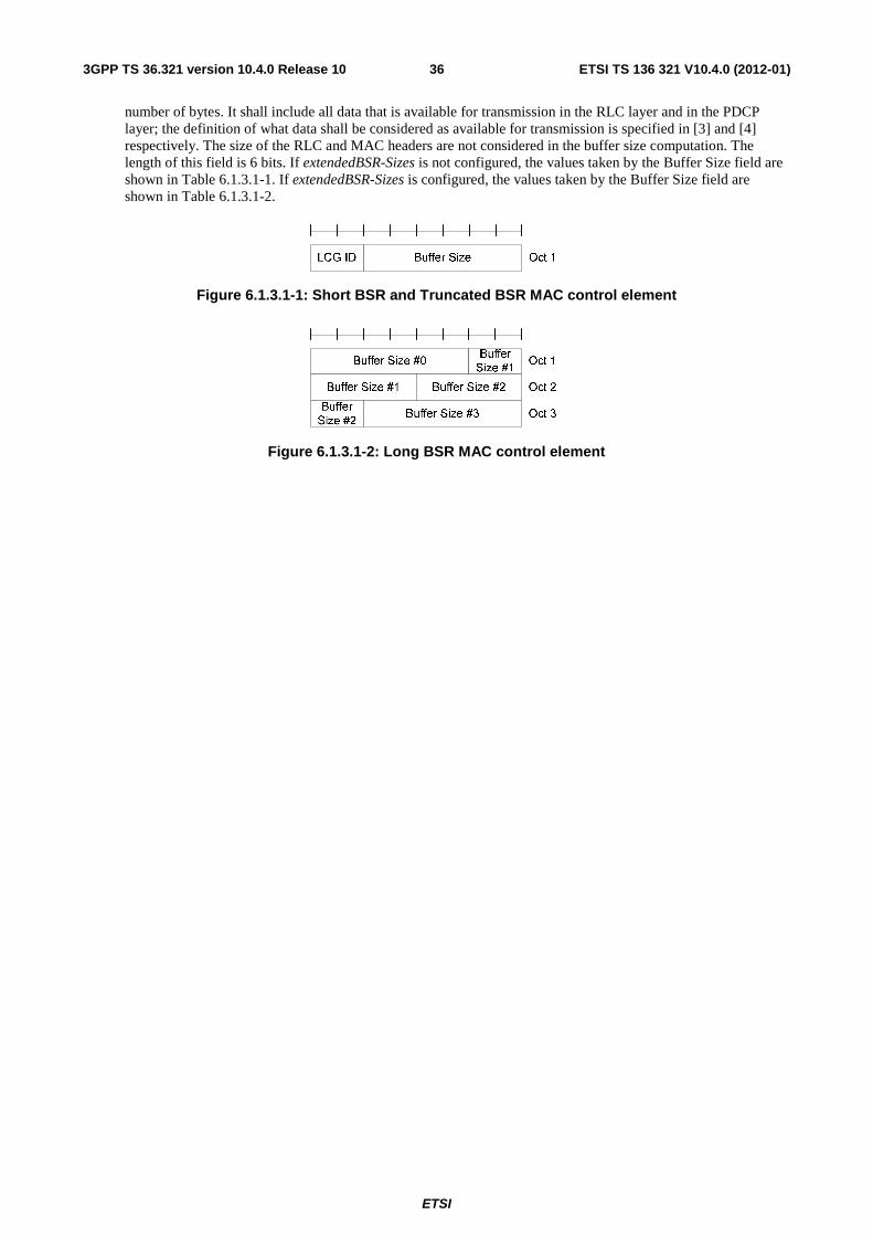
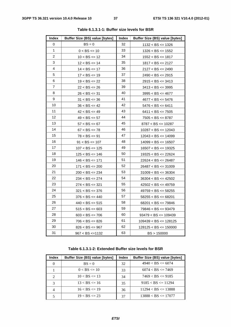
6.1.3.1 Buffer Status Report MAC Control Elements ....................................................................................... 35
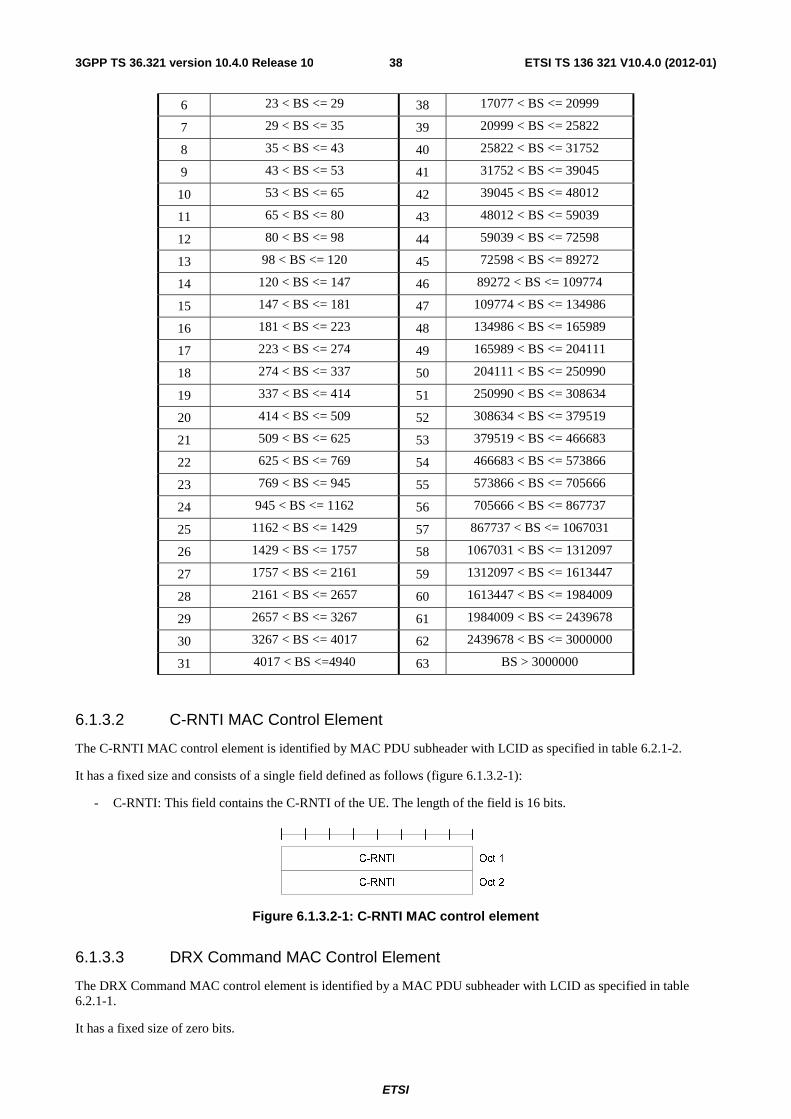
6.1.3.2 C-RNTI MAC Control Element ............................................................................................................ 38
6.1.3.3 DRX Command MAC Control Element ............................................................................................... 38
6.1.3.4 UE Contention Resolution Identity MAC Control Element .................................................................. 39
6.1.3.5 Timing Advance Command MAC Control Element ............................................................................. 39
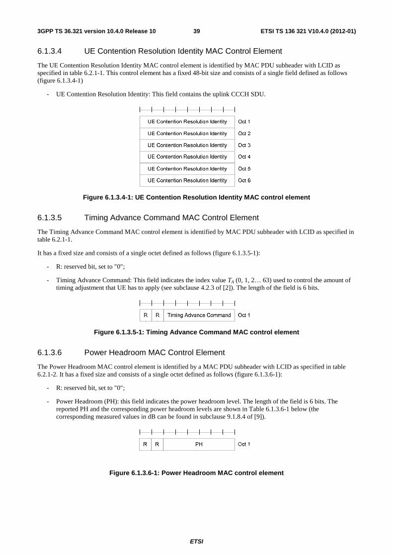
6.1.3.6 Power Headroom MAC Control Element ............................................................................................. 39
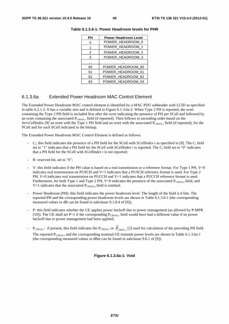
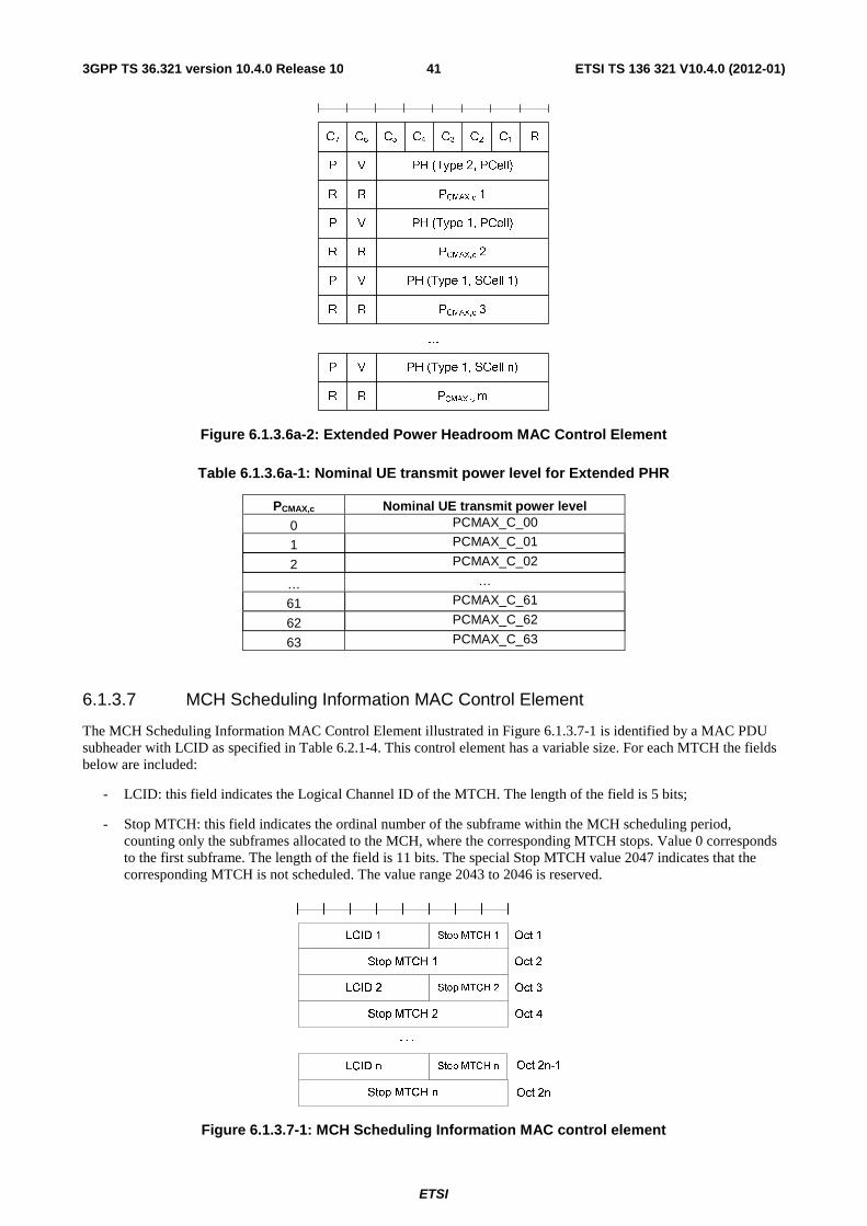
6.1.3.6a Extended Power Headroom MAC Control Element ............................................................................. 40
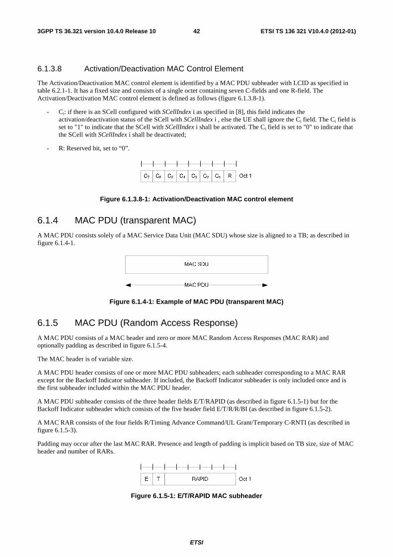
6.1.3.7 MCH Scheduling Information MAC Control Element ......................................................................... 41
6.1.3.8 Activation/Deactivation MAC Control Element ................................................................................... 42
6.1.4 MAC PDU (transparent MAC) ................................................................................................................... 42
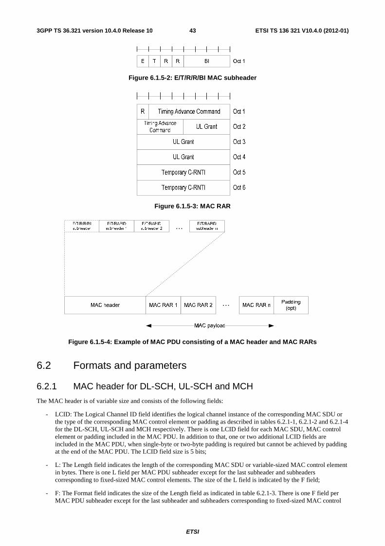
6.1.5 MAC PDU (Random Access Response) ..................................................................................................... 42
6.2 Formats and parameters .................................................................................................................................... 43
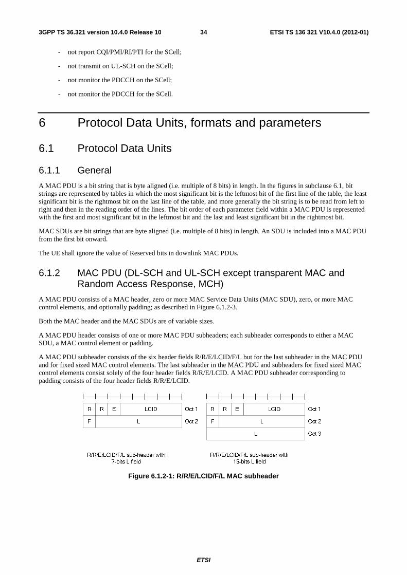
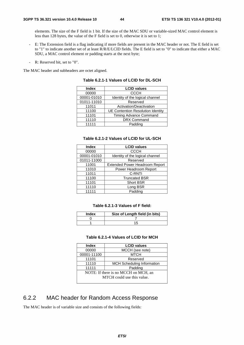
6.2.1 MAC header for DL-SCH, UL-SCH and MCH.......................................................................................... 43
6.2.2 MAC header for Random Access Response ............................................................................................... 44
6.2.3 MAC payload for Random Access Response ............................................................................................. 45
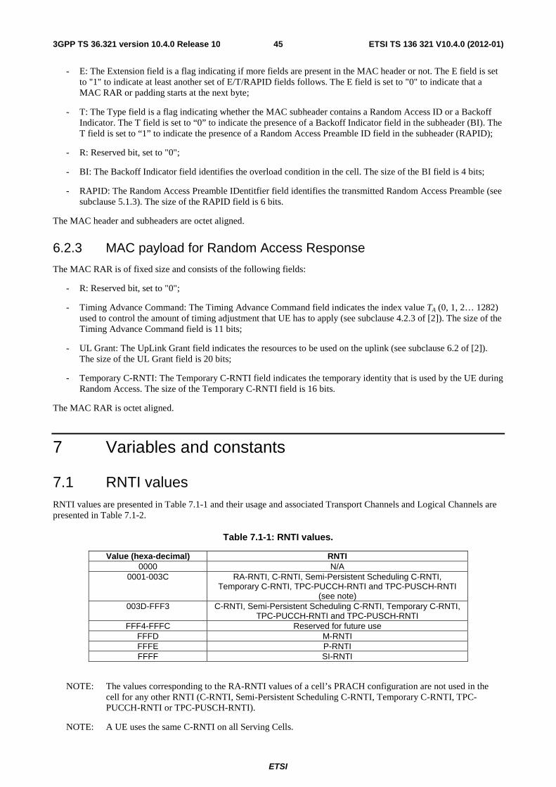
7 Variables and constants .......................................................................................................................... 45
Annex A (normative): Handling of measurement gaps .................................................................... 49
Annex B (normative): Contention resolution for RACH access ...................................................... 50
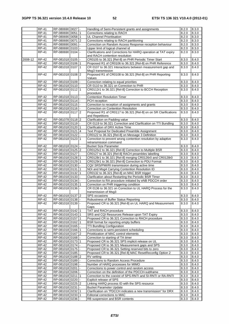
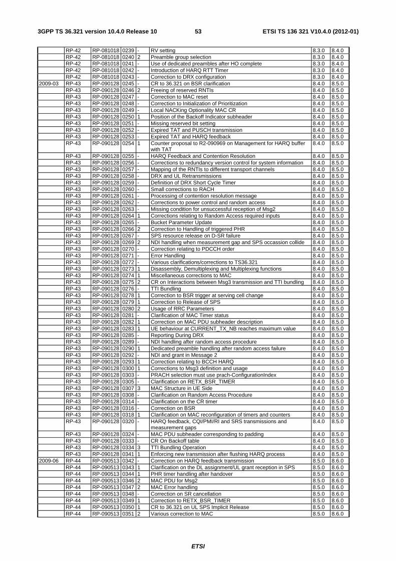
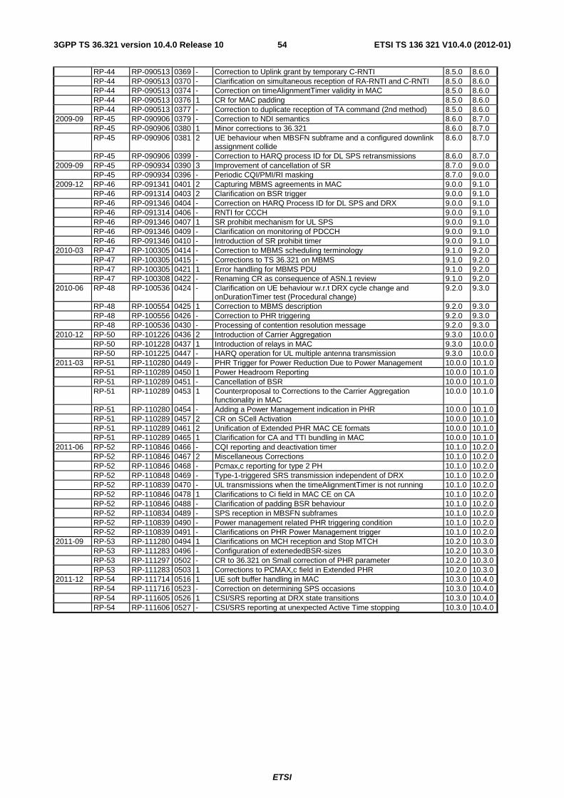
Annex C (informative): Change history ............................................................................................... 51
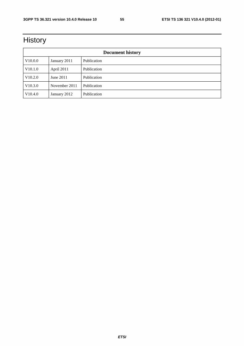
History .............................................................................................................................................................. 55
ETSI
ETSI TS 136 321 V10.4.0 (2012-01)53GPP TS 36.321 version 10.4.0 Release 10
Foreword This Technical Specification has been produced by the 3rd Generation Partnership Project (3GPP).
The contents of the present document are subject to continuing work within the TSG and may change following formal TSG approval. Should the TSG modify the contents of the present document, it will be re-released by the TSG with an identifying change of release date and an increase in version number as follows:
Version x.y.z
where:
x the first digit:
1 presented to TSG for information;
2 presented to TSG for approval;
3 or greater indicates TSG approved document under change control.
y the second digit is incremented for all changes of substance, i.e. technical enhancements, corrections, updates, etc.
z the third digit is incremented when editorial only changes have been incorporated in the document.
ETSI
ETSI TS 136 321 V10.4.0 (2012-01)63GPP TS 36.321 version 10.4.0 Release 10
1 Scope The present document specifies the E-UTRA MAC protocol.
2 References The following documents contain provisions which, through reference in this text, constitute provisions of the present document.
• References are either specific (identified by date of publication, edition number, version number, etc.) or non-specific.
• For a specific reference, subsequent revisions do not apply.
• For a non-specific reference, the latest version applies. In the case of a reference to a 3GPP document (including a GSM document), a non-specific reference implicitly refers to the latest version of that document in the same Release as the present document.
[1] 3GPP TR 21.905: "Vocabulary for 3GPP Specifications".
[7] 3GPP TS 36.211: “Evolved Universal Terrestrial Radio Access (E-UTRA); Physical Channels and Modulation”.
[8] 3GPP TS 36.331: “Evolved Universal Terrestrial Radio Access (E-UTRA); Radio Resource Control (RRC); Protocol specification”.
[9] 3GPP TS 36.133: "Evolved Universal Terrestrial Radio Access (E-UTRA); Requirements for support of radio resource management".
[10] 3GPP TS 36.101: "Evolved Universal Terrestrial Radio Access (E-UTRA); User Equipment (UE) radio transmission and reception".
3 Definitions and abbreviations
3.1 Definitions For the purposes of the present document, the terms and definitions given in TR 21.905 [1] and the following apply. A term defined in the present document takes precedence over the definition of the same term, if any, in TR 21.905 [1].
Active Time: Time related to DRX operation, as defined in subclause 5.7, during which the UE monitors the PDCCH in PDCCH-subframes.
ETSI
ETSI TS 136 321 V10.4.0 (2012-01)73GPP TS 36.321 version 10.4.0 Release 10
mac-ContentionResolutionTimer: Specifies the number of consecutive subframe(s) during which the UE shall monitor the PDCCH after Msg3 is transmitted.
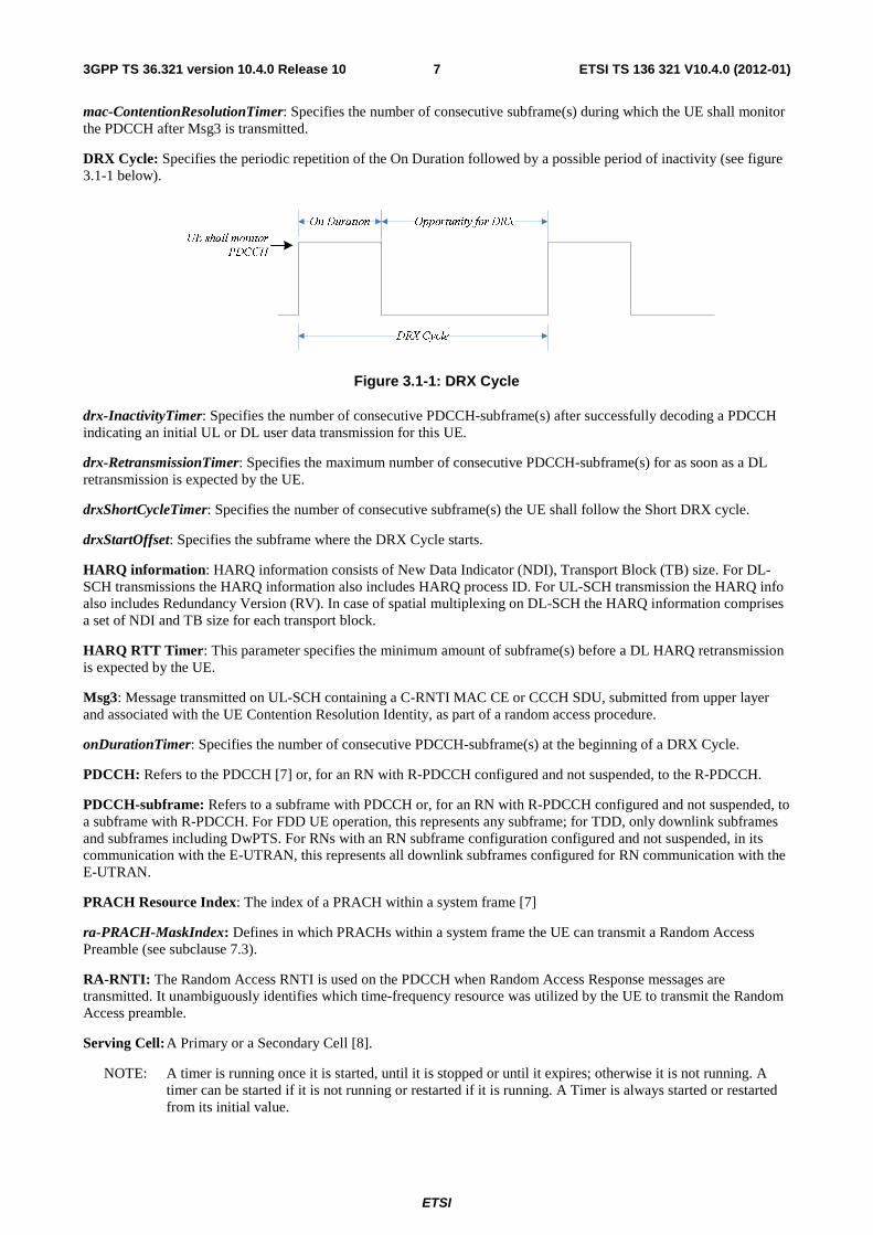
DRX Cycle: Specifies the periodic repetition of the On Duration followed by a possible period of inactivity (see figure 3.1-1 below).
Figure 3.1-1: DRX Cycle
drx-InactivityTimer: Specifies the number of consecutive PDCCH-subframe(s) after successfully decoding a PDCCH indicating an initial UL or DL user data transmission for this UE.
drx-RetransmissionTimer: Specifies the maximum number of consecutive PDCCH-subframe(s) for as soon as a DL retransmission is expected by the UE.
drxShortCycleTimer: Specifies the number of consecutive subframe(s) the UE shall follow the Short DRX cycle.
drxStartOffset: Specifies the subframe where the DRX Cycle starts.
HARQ information: HARQ information consists of New Data Indicator (NDI), Transport Block (TB) size. For DL-SCH transmissions the HARQ information also includes HARQ process ID. For UL-SCH transmission the HARQ info also includes Redundancy Version (RV). In case of spatial multiplexing on DL-SCH the HARQ information comprises a set of NDI and TB size for each transport block.
HARQ RTT Timer: This parameter specifies the minimum amount of subframe(s) before a DL HARQ retransmission is expected by the UE.
Msg3: Message transmitted on UL-SCH containing a C-RNTI MAC CE or CCCH SDU, submitted from upper layer and associated with the UE Contention Resolution Identity, as part of a random access procedure.
onDurationTimer: Specifies the number of consecutive PDCCH-subframe(s) at the beginning of a DRX Cycle.
PDCCH: Refers to the PDCCH [7] or, for an RN with R-PDCCH configured and not suspended, to the R-PDCCH.
PDCCH-subframe: Refers to a subframe with PDCCH or, for an RN with R-PDCCH configured and not suspended, to a subframe with R-PDCCH. For FDD UE operation, this represents any subframe; for TDD, only downlink subframes and subframes including DwPTS. For RNs with an RN subframe configuration configured and not suspended, in its communication with the E-UTRAN, this represents all downlink subframes configured for RN communication with the E-UTRAN.
PRACH Resource Index: The index of a PRACH within a system frame [7]
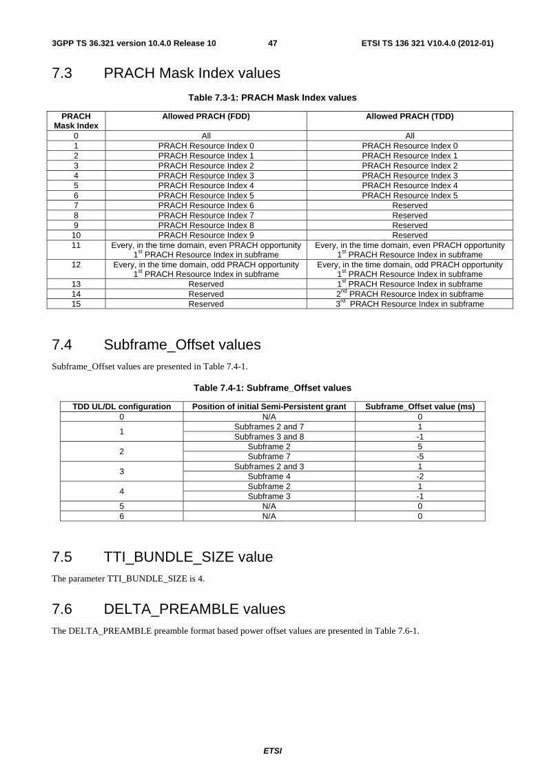
ra-PRACH-MaskIndex: Defines in which PRACHs within a system frame the UE can transmit a Random Access Preamble (see subclause 7.3).
RA-RNTI: The Random Access RNTI is used on the PDCCH when Random Access Response messages are transmitted. It unambiguously identifies which time-frequency resource was utilized by the UE to transmit the Random Access preamble.
Serving Cell: A Primary or a Secondary Cell [8].
NOTE: A timer is running once it is started, until it is stopped or until it expires; otherwise it is not running. A timer can be started if it is not running or restarted if it is running. A Timer is always started or restarted from its initial value.
ETSI
ETSI TS 136 321 V10.4.0 (2012-01)83GPP TS 36.321 version 10.4.0 Release 10
3.2 Abbreviations For the purposes of the present document, the abbreviations given in TR 21.905 [1] and the following apply. An abbreviation defined in the present document takes precedence over the definition of the same abbreviation, if any, in TR 21.905 [1].
BSR Buffer Status Report C-RNTI Cell RNTI CQI Channel Quality Indicator E-UTRA Evolved UMTS Terrestrial Radio Access E-UTRAN Evolved UMTS Terrestrial Radio Access Network MAC Medium Access Control M-RNTI MBMS RNTI LCG Logical Channel Group PCell Primary Cell [8] PHR Power Headroom Report PMI Precoding Matrix Index P-RNTI Paging RNTI PTI Precoding Type Indicator RA-RNTI Random Access RNTI RI Rank Indicator RN Relay Node RNTI Radio Network Temporary Identifier SCell Secondary Cell [8] SI-RNTI System Information RNTI SR Scheduling Request SRS Sounding Reference Symbols TB Transport Block TPC-PUCCH-RNTI Transmit Power Control-Physical Uplink Control Channel-RNTI TPC-PUSCH-RNTI Transmit Power Control-Physical Uplink Shared Channel-RNTI
4 General
4.1 Introduction The objective is to describe the MAC architecture and the MAC entity from a functional point of view. Functionality specified for the UE equally applies to the RN for functionality necessary for the RN. There is also functionality which is only applicable to the RN, in which case the specification denotes the RN instead of the UE. RN-specific behaviour is not applicable to the UE.
4.2 MAC architecture The description in this sub clause is a model and does not specify or restrict implementations.
RRC is in control of configuration of MAC.
4.2.1 MAC Entities
E-UTRA defines two MAC entities; one in the UE and one in the E-UTRAN. These MAC entities handle the following transport channels:
- Broadcast Channel (BCH);
- Downlink Shared Channel(s) (DL-SCH);
- Paging Channel (PCH);
ETSI
ETSI TS 136 321 V10.4.0 (2012-01)93GPP TS 36.321 version 10.4.0 Release 10
- Uplink Shared Channel(s) (UL-SCH);
- Random Access Channel(s) (RACH);
- Multicast Channel(s) (MCH).
The exact functions performed by the MAC entities are different in the UE from those performed in the E-UTRAN.
The RN includes both MAC entities; one for communication with UEs and one for communication with the E-UTRAN.
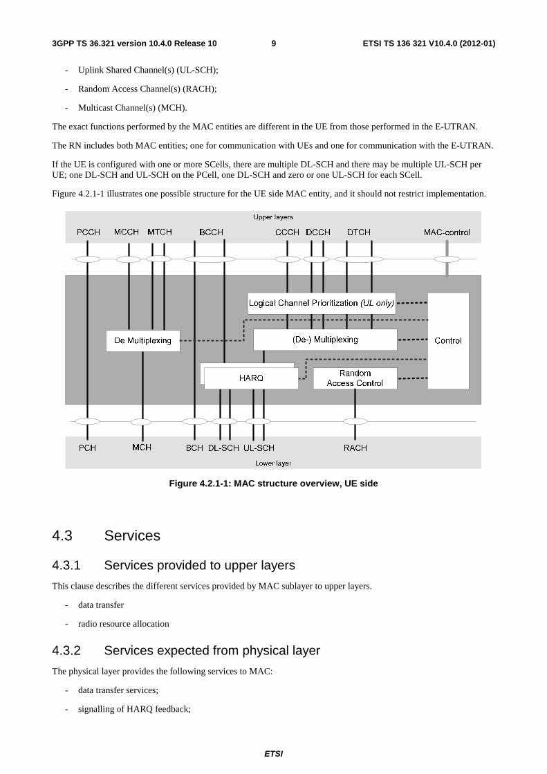
If the UE is configured with one or more SCells, there are multiple DL-SCH and there may be multiple UL-SCH per UE; one DL-SCH and UL-SCH on the PCell, one DL-SCH and zero or one UL-SCH for each SCell.
Figure 4.2.1-1 illustrates one possible structure for the UE side MAC entity, and it should not restrict implementation.
Figure 4.2.1-1: MAC structure overview, UE side
4.3 Services
4.3.1 Services provided to upper layers
This clause describes the different services provided by MAC sublayer to upper layers.
- data transfer
- radio resource allocation
4.3.2 Services expected from physical layer
The physical layer provides the following services to MAC:
- data transfer services;
- signalling of HARQ feedback;
ETSI
ETSI TS 136 321 V10.4.0 (2012-01)103GPP TS 36.321 version 10.4.0 Release 10
The access to the data transfer services is through the use of transport channels. The characteristics of a transport channel are defined by its transport format (or format set), specifying the physical layer processing to be applied to the transport channel in question, such as channel coding and interleaving, and any service-specific rate matching as needed.
4.4 Functions The following functions are supported by MAC sublayer:
- mapping between logical channels and transport channels;
- multiplexing of MAC SDUs from one or different logical channels onto transport blocks (TB) to be delivered to the physical layer on transport channels;
- demultiplexing of MAC SDUs from one or different logical channels from transport blocks (TB) delivered from the physical layer on transport channels;
- scheduling information reporting;
- error correction through HARQ;
- priority handling between UEs by means of dynamic scheduling;
- priority handling between logical channels of one UE;
- Logical Channel prioritisation;
- transport format selection.
The location of the different functions and their relevance for uplink and downlink respectively is illustrated in Table 4.4-1.
Table 4.4-1: MAC function location and link direction association.
MAC function UE eNB Downlink Uplink Mapping between logical channels and transport channels X X X
X X X Multiplexing X X
X X Demultiplexing X X
X X Error correction through HARQ X X X
X X X Transport Format Selection X X X Priority handling between UEs X X X Priority handling between logical channels of one UE X X X Logical Channel prioritisation X X Scheduling information reporting X X
4.5 Channel structure The MAC sublayer operates on the channels defined below; transport channels are SAPs between MAC and Layer 1, logical channels are SAPs between MAC and RLC.
4.5.1 Transport Channels
The transport channels used by MAC are described in Table 4.5.1-1 below.
ETSI
ETSI TS 136 321 V10.4.0 (2012-01)113GPP TS 36.321 version 10.4.0 Release 10
Table 4.5.1-1: Transport channels used by MAC
Transport channel name Acronym Downlink Uplink Broadcast Channel BCH X Downlink Shared Channel DL-SCH X Paging Channel PCH X Multicast Channel MCH X Uplink Shared Channel UL-SCH X Random Access Channel RACH X
4.5.2 Logical Channels
The MAC layer provides data transfer services on logical channels. A set of logical channel types is defined for different kinds of data transfer services as offered by MAC.
Each logical channel type is defined by what type of information is transferred.
MAC provides the control and traffic channels listed in Table 4.5.2-1 below.
Table 4.5.2-1: Logical channels provided by MAC.
Logical channel name Acronym Control channel Traffic channel Broadcast Control Channel BCCH X Paging Control Channel PCCH X Common Control Channel CCCH X Dedicated Control Channel DCCH X Multicast Control Channel MCCH X Dedicated Traffic Channel DTCH X Multicast Traffic Channel MTCH X
4.5.3 Mapping of Transport Channels to Logical Channels
The mapping of logical channels on transport channels depends on the multiplexing that is configured by RRC.
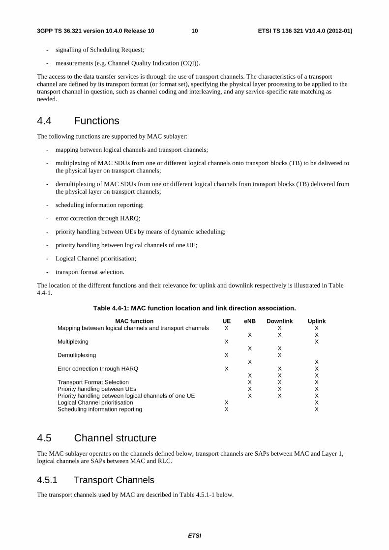
4.5.3.1 Uplink mapping
The MAC entity is responsible for mapping logical channels for the uplink onto uplink transport channels. The uplink logical channels can be mapped as described in Figure 4.5.3.1-1 and Table 4.5.3.1-1.
CCCH DCCH DTCH
UL-SCHRACH
Uplink
Logical channels
Uplink
Transport channels
Figure 4.5.3.1-1
ETSI
ETSI TS 136 321 V10.4.0 (2012-01)123GPP TS 36.321 version 10.4.0 Release 10
Table 4.5.3.1-1: Uplink channel mapping.
Transport channel Logical channel
UL-SCH RACH
CCCH X DCCH X DTCH X
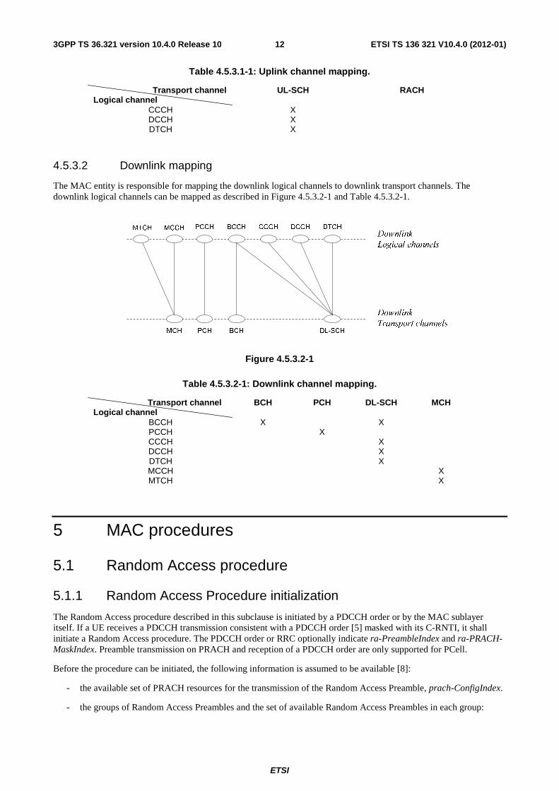
4.5.3.2 Downlink mapping
The MAC entity is responsible for mapping the downlink logical channels to downlink transport channels. The downlink logical channels can be mapped as described in Figure 4.5.3.2-1 and Table 4.5.3.2-1.
Figure 4.5.3.2-1
Table 4.5.3.2-1: Downlink channel mapping.
Transport channel Logical channel
BCH PCH DL-SCH MCH
BCCH X X PCCH X CCCH X DCCH X DTCH X MCCH X MTCH X
5 MAC procedures
5.1 Random Access procedure
5.1.1 Random Access Procedure initialization
The Random Access procedure described in this subclause is initiated by a PDCCH order or by the MAC sublayer itself. If a UE receives a PDCCH transmission consistent with a PDCCH order [5] masked with its C-RNTI, it shall initiate a Random Access procedure. The PDCCH order or RRC optionally indicate ra-PreambleIndex and ra-PRACH-MaskIndex. Preamble transmission on PRACH and reception of a PDCCH order are only supported for PCell.
Before the procedure can be initiated, the following information is assumed to be available [8]:
- the available set of PRACH resources for the transmission of the Random Access Preamble, prach-ConfigIndex.
- the groups of Random Access Preambles and the set of available Random Access Preambles in each group:
ETSI
ETSI TS 136 321 V10.4.0 (2012-01)133GPP TS 36.321 version 10.4.0 Release 10
The preambles that are contained in Random Access Preambles group A and Random Access Preambles group B are calculated from the parameters numberOfRA-Preambles and sizeOfRA-PreamblesGroupA:
If sizeOfRA-PreamblesGroupA is equal to numberOfRA-Preambles then there is no Random Access Preambles group B. The preambles in Random Access Preamble group A are the preambles 0 to sizeOfRA-PreamblesGroupA – 1 and, if it exists, the preambles in Random Access Preamble group B are the preambles sizeOfRA-PreamblesGroupA to numberOfRA-Preambles – 1 from the set of 64 preambles as defined in [7].
- if Random Access Preambles group B exists, the thresholds, messagePowerOffsetGroupB and messageSizeGroupA, the configured UE transmitted power of the Serving Cell performing the Random Access Procedure, PCMAX, c [10], and the offset between the preamble and Msg3, deltaPreambleMsg3, that are required for selecting one of the two groups of Random Access Preambles.
- the RA response window size ra-ResponseWindowSize.
- the power-ramping factor powerRampingStep.
- the maximum number of preamble transmission preambleTransMax.
- the initial preamble power preambleInitialReceivedTargetPower.
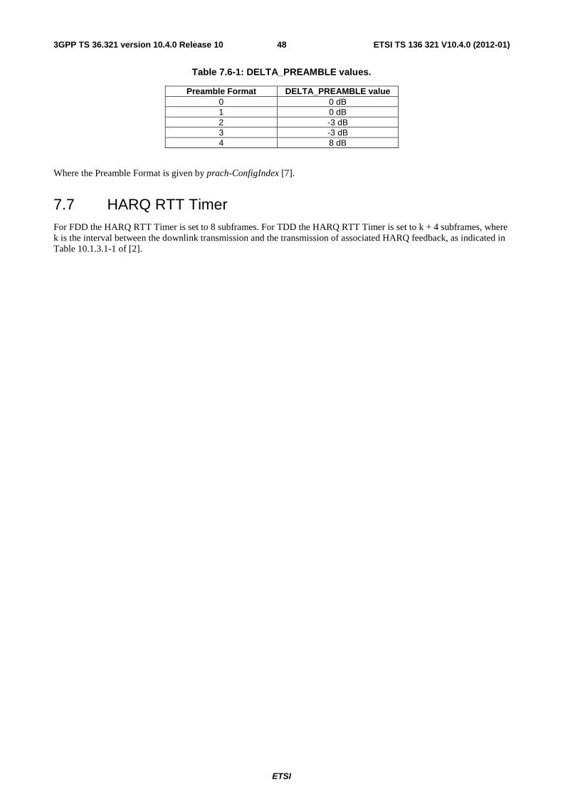
- the preamble format based offset DELTA_PREAMBLE (see subclause 7.6).
- the maximum number of Msg3 HARQ transmissions maxHARQ-Msg3Tx.
- the Contention Resolution Timer mac-ContentionResolutionTimer.
NOTE: The above parameters may be updated from upper layers before each Random Access procedure is initiated.
The Random Access procedure shall be performed as follows:
- Flush the Msg3 buffer;
- set the PREAMBLE_TRANSMISSION_COUNTER to 1;
- set the backoff parameter value in the UE to 0 ms;
- for the RN, suspend any RN subframe configuration;
- proceed to the selection of the Random Access Resource (see subclause 5.1.2).
NOTE: There is only one Random Access procedure ongoing at any point in time. If the UE receives a request for a new Random Access procedure while another is already ongoing, it is up to UE implementation whether to continue with the ongoing procedure or start with the new procedure.
5.1.2 Random Access Resource selection
The Random Access Resource selection procedure shall be performed as follows:
- If ra-PreambleIndex (Random Access Preamble) and ra-PRACH-MaskIndex (PRACH Mask Index) have been explicitly signalled and ra-PreambleIndex is not 000000:
- the Random Access Preamble and the PRACH Mask Index are those explicitly signalled.
- else the Random Access Preamble shall be selected by the UE as follows:
- If Msg3 has not yet been transmitted, the UE shall:
- if Random Access Preambles group B exists and if the potential message size (data available for transmission plus MAC header and, where required, MAC control elements) is greater than messageSizeGroupA and if the pathloss is less than PCMAX,c (of the Serving Cell performing the Random Access Procedure) – preambleInitialReceivedTargetPower – deltaPreambleMsg3 – messagePowerOffsetGroupB, then:
- select the Random Access Preambles group B;
ETSI
ETSI TS 136 321 V10.4.0 (2012-01)143GPP TS 36.321 version 10.4.0 Release 10
- else:
- select the Random Access Preambles group A.
- else, if Msg3 is being retransmitted, the UE shall:
- select the same group of Random Access Preambles as was used for the preamble transmission attempt corresponding to the first transmission of Msg3.
- randomly select a Random Access Preamble within the selected group. The random function shall be such that each of the allowed selections can be chosen with equal probability;
- set PRACH Mask Index to 0.
- determine the next available subframe containing PRACH permitted by the restrictions given by the prach-ConfigIndex, the PRACH Mask Index (see subclause 7.3) and physical layer timing requirements [2] (a UE may take into account the possible occurrence of measurement gaps when determining the next available PRACH subframe);
- if the transmission mode is TDD and the PRACH Mask Index is equal to zero:
- if ra-PreambleIndex was explicitly signalled and it was not 000000 (i.e., not selected by MAC):
- randomly select, with equal probability, one PRACH from the PRACHs available in the determined subframe.
- else:
- randomly select, with equal probability, one PRACH from the PRACHs available in the determined subframe and the next two consecutive subframes.
- else:
- determine a PRACH within the determined subframe in accordance with the requirements of the PRACH Mask Index.
- proceed to the transmission of the Random Access Preamble (see subclause 5.1.3).
5.1.3 Random Access Preamble transmission
The random-access procedure shall be performed as follows:
- set PREAMBLE_RECEIVED_TARGET_POWER to preambleInitialReceivedTargetPower + DELTA_PREAMBLE + (PREAMBLE_TRANSMISSION_COUNTER – 1) * powerRampingStep;
- instruct the physical layer to transmit a preamble using the selected PRACH, corresponding RA-RNTI, preamble index and PREAMBLE_RECEIVED_TARGET_POWER.
5.1.4 Random Access Response reception
Once the Random Access Preamble is transmitted and regardless of the possible occurrence of a measurement gap, the UE shall monitor the PDCCH of the PCell for Random Access Response(s) identified by the RA-RNTI defined below, in the RA Response window which starts at the subframe that contains the end of the preamble transmission [7] plus three subframes and has length ra-ResponseWindowSize subframes. The RA-RNTI associated with the PRACH in which the Random Access Preamble is transmitted, is computed as:
RA-RNTI= 1 + t_id+10*f_id
Where t_id is the index of the first subframe of the specified PRACH (0≤ t_id <10), and f_id is the index of the specified PRACH within that subframe, in ascending order of frequency domain (0≤ f_id< 6). The UE may stop monitoring for Random Access Response(s) after successful reception of a Random Access Response containing Random Access Preamble identifiers that matches the transmitted Random Access Preamble.
- If a downlink assignment for this TTI has been received on the PDCCH for the RA-RNTI and the received TB is successfully decoded, the UE shall regardless of the possible occurrence of a measurement gap:
ETSI
ETSI TS 136 321 V10.4.0 (2012-01)153GPP TS 36.321 version 10.4.0 Release 10
- if the Random Access Response contains a Backoff Indicator subheader:
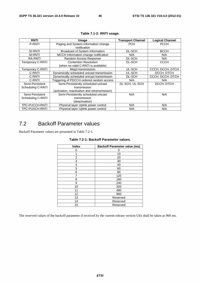
- set the backoff parameter value in the UE as indicated by the BI field of the Backoff Indicator subheader and Table 7.2-1.
- else, set the backoff parameter value in the UE to 0 ms.
- if the Random Access Response contains a Random Access Preamble identifier corresponding to the transmitted Random Access Preamble (see subclause 5.1.3), the UE shall:
- consider this Random Access Response reception successful;
- process the received Timing Advance Command (see subclause 5.2);
- indicate the preambleInitialReceivedTargetPower and the amount of power ramping applied to the latest preamble transmission to lower layers (i.e., (PREAMBLE_TRANSMISSION_COUNTER – 1) * powerRampingStep);
- process the received UL grant value and indicate it to the lower layers;
- if ra-PreambleIndex was explicitly signalled and it was not 000000 (i.e., not selected by MAC):
- consider the Random Access procedure successfully completed.
- else, if the Random Access Preamble was selected by UE MAC:
- set the Temporary C-RNTI to the value received in the Random Access Response message no later than at the time of the first transmission corresponding to the UL grant provided in the Random Access Response message;
- if this is the first successfully received Random Access Response within this Random Access procedure:
- if the transmission is not being made for the CCCH logical channel, indicate to the Multiplexing and assembly entity to include a C-RNTI MAC control element in the subsequent uplink transmission;
- obtain the MAC PDU to transmit from the "Multiplexing and assembly" entity and store it in the Msg3 buffer.
NOTE: When an uplink transmission is required, e.g., for contention resolution, the eNB should not provide a grant smaller than 56 bits in the Random Access Response.
NOTE: If within a Random Access procedure, an uplink grant provided in the Random Access Response for the same group of Random Access Preambles has a different size than the first uplink grant allocated during that Random Access procedure, the UE behavior is not defined.
NOTE: The UL grant value received in the Random Access Response is valid for the PCell.
If no Random Access Response is received within the RA Response window, or if none of all received Random Access Responses contains a Random Access Preamble identifier corresponding to the transmitted Random Access Preamble, the Random Access Response reception is considered not successful and the UE shall:
- increment PREAMBLE_TRANSMISSION_COUNTER by 1;
- If PREAMBLE_TRANSMISSION_COUNTER = preambleTransMax + 1:
- indicate a Random Access problem to upper layers.
- if in this Random Access procedure, the Random Access Preamble was selected by MAC:
- based on the backoff parameter in the UE, select a random backoff time according to a uniform distribution between 0 and the Backoff Parameter Value;
- delay the subsequent Random Access transmission by the backoff time;
- proceed to the selection of a Random Access Resource (see subclause 5.1.2).
ETSI
ETSI TS 136 321 V10.4.0 (2012-01)163GPP TS 36.321 version 10.4.0 Release 10
5.1.5 Contention Resolution
Contention Resolution is based on either C-RNTI on PDCCH of the PCell or UE Contention Resolution Identity on DL-SCH.
Once Msg3 is transmitted, the UE shall:
- start mac-ContentionResolutionTimer and restart mac-ContentionResolutionTimer at each HARQ retransmission;
- regardless of the possible occurrence of a measurement gap, monitor the PDCCH until mac-ContentionResolutionTimer expires or is stopped;
- if notification of a reception of a PDCCH transmission is received from lower layers, the UE shall:
- if the C-RNTI MAC control element was included in Msg3:
- if the Random Access procedure was initiated by the MAC sublayer itself and the PDCCH transmission is addressed to the C-RNTI and contains an UL grant for a new transmission; or
- if the Random Access procedure was initiated by a PDCCH order and the PDCCH transmission is addressed to the C-RNTI:
- consider this Contention Resolution successful;
- stop mac-ContentionResolutionTimer;
- discard the Temporary C-RNTI;
- consider this Random Access procedure successfully completed.
- else if the CCCH SDU was included in Msg3 and the PDCCH transmission is addressed to its Temporary C-RNTI:
- if the MAC PDU is successfully decoded:
- stop mac-ContentionResolutionTimer;
- if the MAC PDU contains a UE Contention Resolution Identity MAC control element; and
- if the UE Contention Resolution Identity included in the MAC control element matches the CCCH SDU transmitted in Msg3:
- consider this Contention Resolution successful and finish the disassembly and demultiplexing of the MAC PDU;
- set the C-RNTI to the value of the Temporary C-RNTI;
- discard the Temporary C-RNTI;
- consider this Random Access procedure successfully completed.
- else
- discard the Temporary C-RNTI;
- consider this Contention Resolution not successful and discard the successfully decoded MAC PDU.
- if mac-ContentionResolutionTimer expires:
- discard the Temporary C-RNTI;
- consider the Contention Resolution not successful.
- if the Contention Resolution is considered not successful the UE shall:
- flush the HARQ buffer used for transmission of the MAC PDU in the Msg3 buffer;
ETSI
ETSI TS 136 321 V10.4.0 (2012-01)173GPP TS 36.321 version 10.4.0 Release 10
- increment PREAMBLE_TRANSMISSION_COUNTER by 1;
- If PREAMBLE_TRANSMISSION_COUNTER = preambleTransMax + 1:
- indicate a Random Access problem to upper layers.
- based on the backoff parameter in the UE, select a random backoff time according to a uniform distribution between 0 and the Backoff Parameter Value;
- delay the subsequent Random Access transmission by the backoff time;
- proceed to the selection of a Random Access Resource (see subclause 5.1.2).
5.1.6 Completion of the Random Access procedure
At successful completion of the Random Access procedure, the UE shall:
- discard explicitly signalled ra-PreambleIndex and ra-PRACH-MaskIndex, if any;
- flush the HARQ buffer used for transmission of the MAC PDU in the Msg3 buffer.
In addition, the RN shall resume the suspended RN subframe configuration, if any.
5.2 Maintenance of Uplink Time Alignment The UE has a configurable timer timeAlignmentTimer which is used to control how long the UE is considered uplink time aligned [8].
The UE shall:
- when a Timing Advance Command MAC control element is received:
- apply the Timing Advance Command;
- start or restart timeAlignmentTimer.
- when a Timing Advance Command is received in a Random Access Response message:
- if the Random Access Preamble was not selected by UE MAC:
- apply the Timing Advance Command;
- start or restart timeAlignmentTimer.
- else, if the timeAlignmentTimer is not running:
- apply the Timing Advance Command;
- start timeAlignmentTimer;
- when the contention resolution is considered not successful as described in subclause 5.1.5, stop timeAlignmentTimer.
- else:
- ignore the received Timing Advance Command.
- when timeAlignmentTimer expires:
- flush all HARQ buffers;
- notify RRC to release PUCCH/SRS;
- clear any configured downlink assignments and uplink grants.
ETSI
ETSI TS 136 321 V10.4.0 (2012-01)183GPP TS 36.321 version 10.4.0 Release 10
The UE shall not perform any uplink transmission except the Random Access Preamble transmission when timeAlignmentTimer is not running.
5.3 DL-SCH data transfer
5.3.1 DL Assignment reception
Downlink assignments transmitted on the PDCCH indicate if there is a transmission on a DL-SCH for a particular UE and provide the relevant HARQ information.
When the UE has a C-RNTI, Semi-Persistent Scheduling C-RNTI, or Temporary C-RNTI, the UE shall for each TTI during which it monitors PDCCH and for each Serving Cell:
- if a downlink assignment for this TTI and this Serving Cell has been received on the PDCCH for the UE’s C-RNTI, or Temporary C-RNTI:
- if this is the first downlink assignment for this Temporary C-RNTI:
- consider the NDI to have been toggled.
- if the downlink assignment is for UE’s C-RNTI and if the previous downlink assignment indicated to the HARQ entity of the same HARQ process was either a downlink assignment received for the UE’s Semi-Persistent Scheduling C-RNTI or a configured downlink assignment:
- consider the NDI to have been toggled regardless of the value of the NDI.
- indicate the presence of a downlink assignment and deliver the associated HARQ information to the HARQ entity for this TTI.
- else, if this Serving Cell is the PCell and a downlink assignment for this TTI has been received for the PCell on the PDCCH of the PCell for the UE’s Semi-Persistent Scheduling C-RNTI:
- if the NDI in the received HARQ information is 1:
- consider the NDI not to have been toggled;
- indicate the presence of a downlink assignment and deliver the associated HARQ information to the HARQ entity for this TTI.
- else, if the NDI in the received HARQ information is 0:
- if PDCCH contents indicate SPS release:
- clear the configured downlink assignment (if any);
- if timeAlignmentTimer is running:
- indicate a positive acknowledgement for the downlink SPS release to the physical layer.
- else:
- store the downlink assignment and the associated HARQ information as configured downlink assignment;
- initialise (if not active) or re-initialise (if already active) the configured downlink assignment to start in this TTI and to recur according to rules in subclause 5.10.1;
- set the HARQ Process ID to the HARQ Process ID associated with this TTI;
- consider the NDI bit to have been toggled;
- indicate the presence of a configured downlink assignment and deliver the stored HARQ information to the HARQ entity for this TTI.
ETSI
ETSI TS 136 321 V10.4.0 (2012-01)193GPP TS 36.321 version 10.4.0 Release 10
- else, if this Serving Cell is the PCell and a downlink assignment for this TTI has been configured for the PCell and there is no measurement gap in this TTI; and
- if this TTI is not an MBSFN subframe of the PCell or the UE is configured with transmission mode tm9 on the PCell:
- instruct the physical layer to receive, in this TTI, transport block on the DL-SCH according to the configured downlink assignment and to deliver it to the HARQ entity;
- set the HARQ Process ID to the HARQ Process ID associated with this TTI;
- consider the NDI bit to have been toggled;
- indicate the presence of a configured downlink assignment and deliver the stored HARQ information to the HARQ entity for this TTI.
For configured downlink assignments, the HARQ Process ID associated with this TTI is derived from the following equation:
HARQ Process ID = [floor(CURRENT_TTI/semiPersistSchedIntervalDL)] modulo numberOfConfSPS-Processes,
where CURRENT_TTI=[(SFN * 10) + subframe number].
When the UE needs to read BCCH, the UE may, based on the scheduling information from RRC:
- if a downlink assignment for this TTI has been received on the PDCCH of the PCell for the SI-RNTI;
- if the redundancy version is not defined in the PDCCH format:
- the redundancy version of the received downlink assignment for this TTI is determined by RVK = ceiling(3/2*k) modulo 4, where k depends on the type of system information message: for SystemInformationBlockType1 message, k = (SFN/2) modulo 4, where SFN is the system frame number; for SystemInformation messages, k=i modulo 4, i =0,1,…, ns
w–1, where i denotes the subframe number within the SI window ns
w;
- indicate a downlink assignment and redundancy version for the dedicated broadcast HARQ process to the HARQ entity for this TTI.
5.3.2 HARQ operation
5.3.2.1 HARQ Entity
There is one HARQ entity at the UE for each Serving Cell which maintains a number of parallel HARQ processes. Each HARQ process is associated with a HARQ process identifier. The HARQ entity directs HARQ information and associated TBs received on the DL-SCH to the corresponding HARQ processes (see subclause 5.3.2.2).
The number of DL HARQ processes per HARQ entity is specified in [2], clause 7.
When the physical layer is configured for downlink spatial multiplexing [2], one or two TBs are expected per subframe and they are associated with the same HARQ process. Otherwise, one TB is expected per subframe.
The UE shall:
- If a downlink assignment has been indicated for this TTI:
- allocate the TB(s) received from the physical layer and the associated HARQ information to the HARQ process indicated by the associated HARQ information.
- If a downlink assignment has been indicated for the broadcast HARQ process:
- allocate the received TB to the broadcast HARQ process.
NOTE: In case of BCCH a dedicated broadcast HARQ process is used.
ETSI
ETSI TS 136 321 V10.4.0 (2012-01)203GPP TS 36.321 version 10.4.0 Release 10
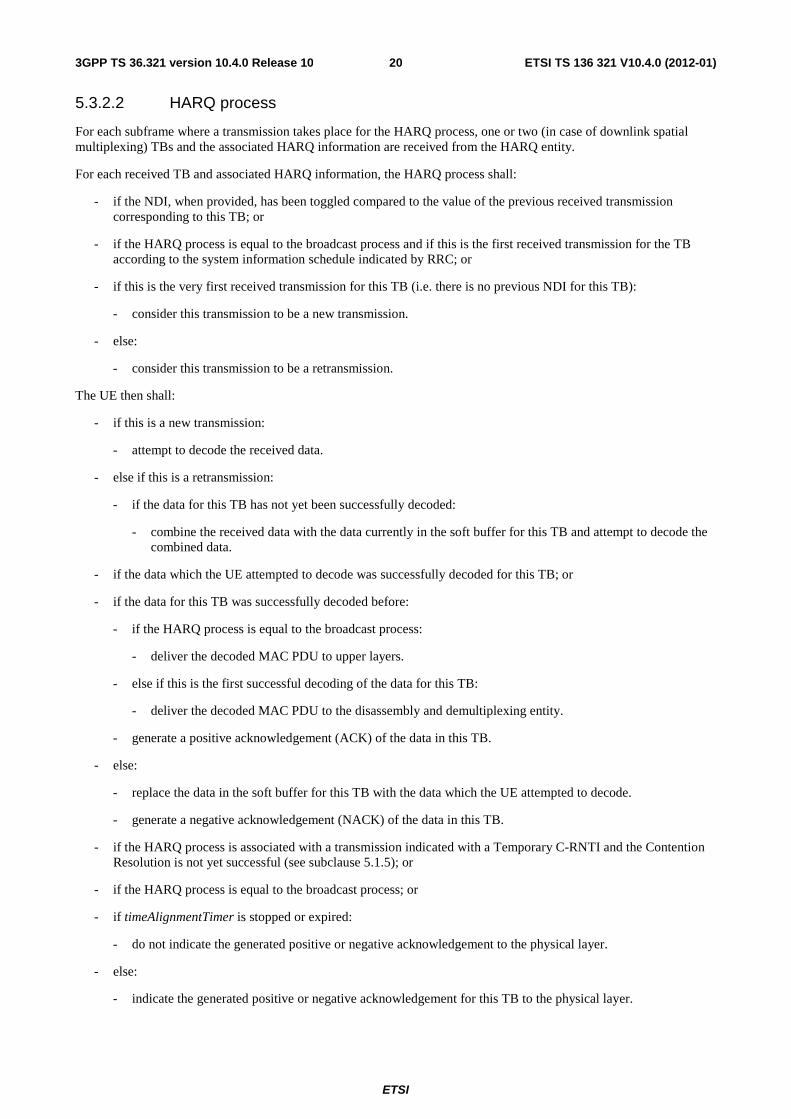
5.3.2.2 HARQ process
For each subframe where a transmission takes place for the HARQ process, one or two (in case of downlink spatial multiplexing) TBs and the associated HARQ information are received from the HARQ entity.
For each received TB and associated HARQ information, the HARQ process shall:
- if the NDI, when provided, has been toggled compared to the value of the previous received transmission corresponding to this TB; or
- if the HARQ process is equal to the broadcast process and if this is the first received transmission for the TB according to the system information schedule indicated by RRC; or
- if this is the very first received transmission for this TB (i.e. there is no previous NDI for this TB):
- consider this transmission to be a new transmission.
- else:
- consider this transmission to be a retransmission.
The UE then shall:
- if this is a new transmission:
- attempt to decode the received data.
- else if this is a retransmission:
- if the data for this TB has not yet been successfully decoded:
- combine the received data with the data currently in the soft buffer for this TB and attempt to decode the combined data.
- if the data which the UE attempted to decode was successfully decoded for this TB; or
- if the data for this TB was successfully decoded before:
- if the HARQ process is equal to the broadcast process:
- deliver the decoded MAC PDU to upper layers.
- else if this is the first successful decoding of the data for this TB:
- deliver the decoded MAC PDU to the disassembly and demultiplexing entity.
- generate a positive acknowledgement (ACK) of the data in this TB.
- else:
- replace the data in the soft buffer for this TB with the data which the UE attempted to decode.
- generate a negative acknowledgement (NACK) of the data in this TB.
- if the HARQ process is associated with a transmission indicated with a Temporary C-RNTI and the Contention Resolution is not yet successful (see subclause 5.1.5); or
- if the HARQ process is equal to the broadcast process; or
- if timeAlignmentTimer is stopped or expired:
- do not indicate the generated positive or negative acknowledgement to the physical layer.
- else:
- indicate the generated positive or negative acknowledgement for this TB to the physical layer.
ETSI
ETSI TS 136 321 V10.4.0 (2012-01)213GPP TS 36.321 version 10.4.0 Release 10
The UE shall ignore NDI received in all downlink assignments on PDCCH for its Temporary C-RNTI when determining if NDI on PDCCH for its C-RNTI has been toggled compared to the value in the previous transmission.
NOTE: When the UE is configured with more than one serving cell, UE behaviors for storing data to the soft buffer is specified in [2].
NOTE: If the UE receives a retransmission with a TB size different from the last valid TB size signalled for this TB, the UE behavior is left up to UE implementation.
5.3.3 Disassembly and demultiplexing
The UE shall disassemble and demultiplex a MAC PDU as defined in subclause 6.1.2.
5.4 UL-SCH data transfer
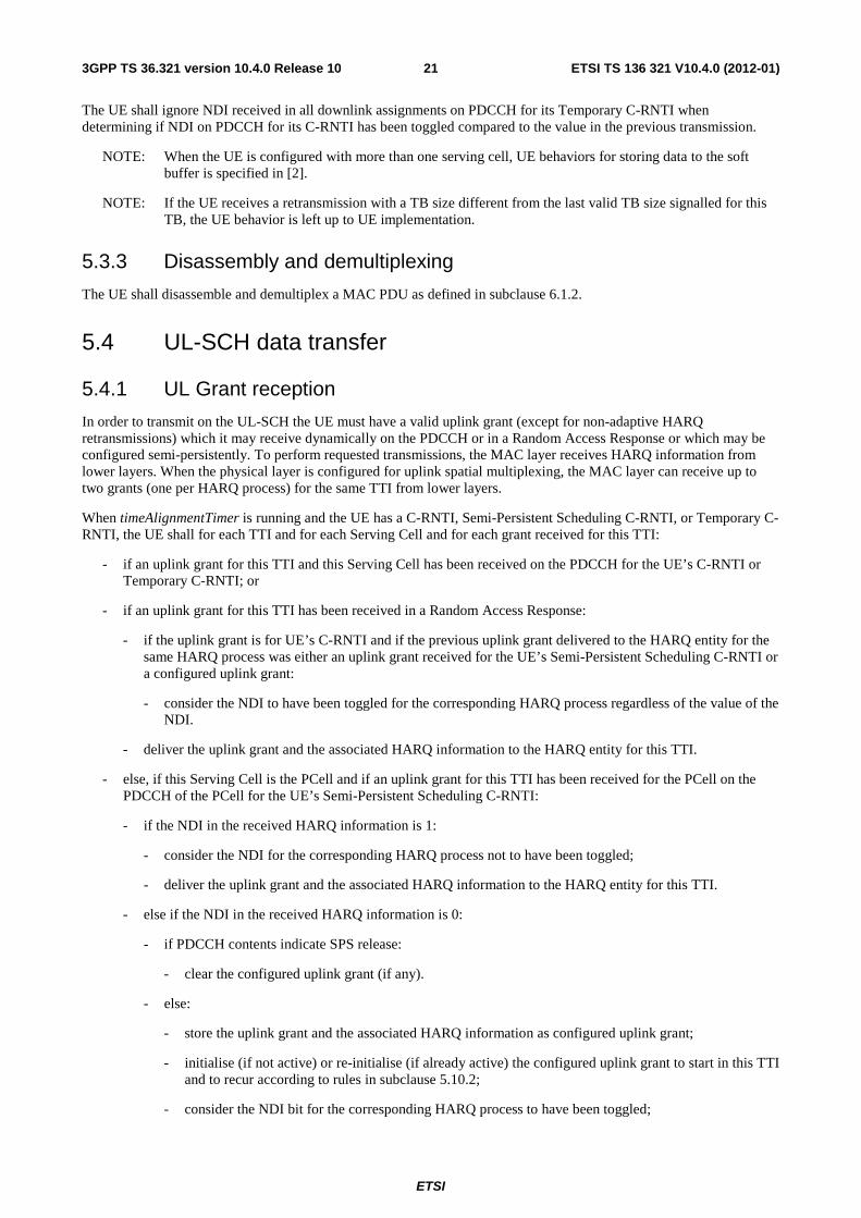
5.4.1 UL Grant reception
In order to transmit on the UL-SCH the UE must have a valid uplink grant (except for non-adaptive HARQ retransmissions) which it may receive dynamically on the PDCCH or in a Random Access Response or which may be configured semi-persistently. To perform requested transmissions, the MAC layer receives HARQ information from lower layers. When the physical layer is configured for uplink spatial multiplexing, the MAC layer can receive up to two grants (one per HARQ process) for the same TTI from lower layers.
When timeAlignmentTimer is running and the UE has a C-RNTI, Semi-Persistent Scheduling C-RNTI, or Temporary C-RNTI, the UE shall for each TTI and for each Serving Cell and for each grant received for this TTI:
- if an uplink grant for this TTI and this Serving Cell has been received on the PDCCH for the UE’s C-RNTI or Temporary C-RNTI; or
- if an uplink grant for this TTI has been received in a Random Access Response:
- if the uplink grant is for UE’s C-RNTI and if the previous uplink grant delivered to the HARQ entity for the same HARQ process was either an uplink grant received for the UE’s Semi-Persistent Scheduling C-RNTI or a configured uplink grant:
- consider the NDI to have been toggled for the corresponding HARQ process regardless of the value of the NDI.
- deliver the uplink grant and the associated HARQ information to the HARQ entity for this TTI.
- else, if this Serving Cell is the PCell and if an uplink grant for this TTI has been received for the PCell on the PDCCH of the PCell for the UE’s Semi-Persistent Scheduling C-RNTI:
- if the NDI in the received HARQ information is 1:
- consider the NDI for the corresponding HARQ process not to have been toggled;
- deliver the uplink grant and the associated HARQ information to the HARQ entity for this TTI.
- else if the NDI in the received HARQ information is 0:
- if PDCCH contents indicate SPS release:
- clear the configured uplink grant (if any).
- else:
- store the uplink grant and the associated HARQ information as configured uplink grant;
- initialise (if not active) or re-initialise (if already active) the configured uplink grant to start in this TTI and to recur according to rules in subclause 5.10.2;
- consider the NDI bit for the corresponding HARQ process to have been toggled;
ETSI
ETSI TS 136 321 V10.4.0 (2012-01)223GPP TS 36.321 version 10.4.0 Release 10
- deliver the configured uplink grant and the associated HARQ information to the HARQ entity for this TTI.
- else, if this Serving Cell is the PCell and an uplink grant for this TTI has been configured for the PCell:
- consider the NDI bit for the corresponding HARQ process to have been toggled;
- deliver the configured uplink grant, and the associated HARQ information to the HARQ entity for this TTI.
NOTE: The period of configured uplink grants is expressed in TTIs.
NOTE: If the UE receives both a grant in a Random Access Response and a grant for its C-RNTI or Semi persistent scheduling C-RNTI requiring transmissions on the PCell in the same UL subframe, the UE may choose to continue with either the grant for its RA-RNTI or the grant for its C-RNTI or Semi persistent scheduling C-RNTI.
NOTE: When a configured uplink grant is indicated during a measurement gap and indicates an UL-SCH transmission during a measurement gap, the UE processes the grant but does not transmit on UL-SCH.
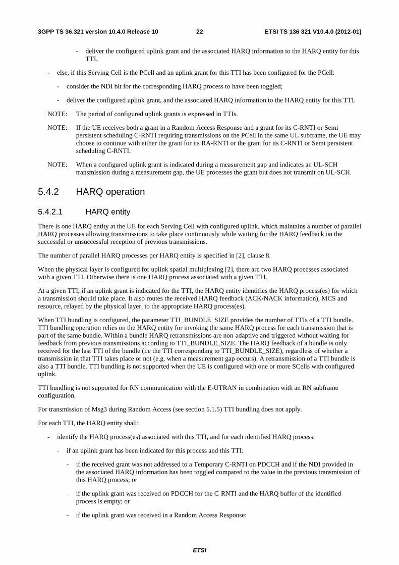
5.4.2 HARQ operation
5.4.2.1 HARQ entity
There is one HARQ entity at the UE for each Serving Cell with configured uplink, which maintains a number of parallel HARQ processes allowing transmissions to take place continuously while waiting for the HARQ feedback on the successful or unsuccessful reception of previous transmissions.
The number of parallel HARQ processes per HARQ entity is specified in [2], clause 8.
When the physical layer is configured for uplink spatial multiplexing [2], there are two HARQ processes associated with a given TTI. Otherwise there is one HARQ process associated with a given TTI.
At a given TTI, if an uplink grant is indicated for the TTI, the HARQ entity identifies the HARQ process(es) for which a transmission should take place. It also routes the received HARQ feedback (ACK/NACK information), MCS and resource, relayed by the physical layer, to the appropriate HARQ process(es).
When TTI bundling is configured, the parameter TTI_BUNDLE_SIZE provides the number of TTIs of a TTI bundle. TTI bundling operation relies on the HARQ entity for invoking the same HARQ process for each transmission that is part of the same bundle. Within a bundle HARQ retransmissions are non-adaptive and triggered without waiting for feedback from previous transmissions according to TTI_BUNDLE_SIZE. The HARQ feedback of a bundle is only received for the last TTI of the bundle (i.e the TTI corresponding to TTI_BUNDLE_SIZE), regardless of whether a transmission in that TTI takes place or not (e.g. when a measurement gap occurs). A retransmission of a TTI bundle is also a TTI bundle. TTI bundling is not supported when the UE is configured with one or more SCells with configured uplink.
TTI bundling is not supported for RN communication with the E-UTRAN in combination with an RN subframe configuration.
For transmission of Msg3 during Random Access (see section 5.1.5) TTI bundling does not apply.
For each TTI, the HARQ entity shall:
- identify the HARQ process(es) associated with this TTI, and for each identified HARQ process:
- if an uplink grant has been indicated for this process and this TTI:
- if the received grant was not addressed to a Temporary C-RNTI on PDCCH and if the NDI provided in the associated HARQ information has been toggled compared to the value in the previous transmission of this HARQ process; or
- if the uplink grant was received on PDCCH for the C-RNTI and the HARQ buffer of the identified process is empty; or
- if the uplink grant was received in a Random Access Response:
ETSI
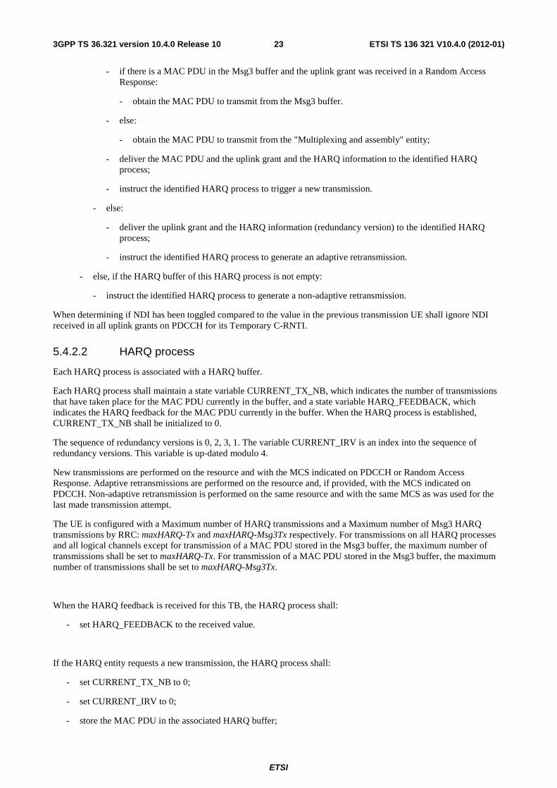
ETSI TS 136 321 V10.4.0 (2012-01)233GPP TS 36.321 version 10.4.0 Release 10
- if there is a MAC PDU in the Msg3 buffer and the uplink grant was received in a Random Access Response:
- obtain the MAC PDU to transmit from the Msg3 buffer.
- else:
- obtain the MAC PDU to transmit from the "Multiplexing and assembly" entity;
- deliver the MAC PDU and the uplink grant and the HARQ information to the identified HARQ process;
- instruct the identified HARQ process to trigger a new transmission.
- else:
- deliver the uplink grant and the HARQ information (redundancy version) to the identified HARQ process;
- instruct the identified HARQ process to generate an adaptive retransmission.
- else, if the HARQ buffer of this HARQ process is not empty:
- instruct the identified HARQ process to generate a non-adaptive retransmission.
When determining if NDI has been toggled compared to the value in the previous transmission UE shall ignore NDI received in all uplink grants on PDCCH for its Temporary C-RNTI.
5.4.2.2 HARQ process
Each HARQ process is associated with a HARQ buffer.
Each HARQ process shall maintain a state variable CURRENT_TX_NB, which indicates the number of transmissions that have taken place for the MAC PDU currently in the buffer, and a state variable HARQ_FEEDBACK, which indicates the HARQ feedback for the MAC PDU currently in the buffer. When the HARQ process is established, CURRENT_TX_NB shall be initialized to 0.
The sequence of redundancy versions is 0, 2, 3, 1. The variable CURRENT_IRV is an index into the sequence of redundancy versions. This variable is up-dated modulo 4.
New transmissions are performed on the resource and with the MCS indicated on PDCCH or Random Access Response. Adaptive retransmissions are performed on the resource and, if provided, with the MCS indicated on PDCCH. Non-adaptive retransmission is performed on the same resource and with the same MCS as was used for the last made transmission attempt.
The UE is configured with a Maximum number of HARQ transmissions and a Maximum number of Msg3 HARQ transmissions by RRC: maxHARQ-Tx and maxHARQ-Msg3Tx respectively. For transmissions on all HARQ processes and all logical channels except for transmission of a MAC PDU stored in the Msg3 buffer, the maximum number of transmissions shall be set to maxHARQ-Tx. For transmission of a MAC PDU stored in the Msg3 buffer, the maximum number of transmissions shall be set to maxHARQ-Msg3Tx.
When the HARQ feedback is received for this TB, the HARQ process shall:
- set HARQ_FEEDBACK to the received value.
If the HARQ entity requests a new transmission, the HARQ process shall:
- set CURRENT_TX_NB to 0;
- set CURRENT_IRV to 0;
- store the MAC PDU in the associated HARQ buffer;
ETSI
ETSI TS 136 321 V10.4.0 (2012-01)243GPP TS 36.321 version 10.4.0 Release 10
- store the uplink grant received from the HARQ entity;
- set HARQ_FEEDBACK to NACK;
- generate a transmission as described below.
If the HARQ entity requests a retransmission, the HARQ process shall:
- increment CURRENT_TX_NB by 1;
- if the HARQ entity requests an adaptive retransmission:
- store the uplink grant received from the HARQ entity;
- set CURRENT_IRV to the index corresponding to the redundancy version value provided in the HARQ information;
- set HARQ_FEEDBACK to NACK;
- generate a transmission as described below.
- else if the HARQ entity requests a non-adaptive retransmission:
- if HARQ_FEEDBACK = NACK:
- generate a transmission as described below.
NOTE: When receiving a HARQ ACK alone, the UE keeps the data in the HARQ buffer.
NOTE: When no UL-SCH transmission can be made due to the occurrence of a measurement gap, no HARQ feedback can be received and a non-adaptive retransmission follows.
To generate a transmission, the HARQ process shall:
- if the MAC PDU was obtained from the Msg3 buffer; or
- if there is no measurement gap at the time of the transmission and, in case of retransmission, the retransmission does not collide with a transmission for a MAC PDU obtained from the Msg3 buffer in this TTI:
- instruct the physical layer to generate a transmission according to the stored uplink grant with the redundancy version corresponding to the CURRENT_IRV value;
- increment CURRENT_IRV by 1;
- if there is a measurement gap at the time of the HARQ feedback reception for this transmission and if the MAC PDU was not obtained from the Msg3 buffer:
- set HARQ_FEEDBACK to ACK at the time of the HARQ feedback reception for this transmission.
After performing above actions, the HARQ process then shall:
- if CURRENT_TX_NB = maximum number of transmissions – 1:
- flush the HARQ buffer;
ETSI
ETSI TS 136 321 V10.4.0 (2012-01)253GPP TS 36.321 version 10.4.0 Release 10
5.4.3 Multiplexing and assembly
5.4.3.1 Logical channel prioritization
The Logical Channel Prioritization procedure is applied when a new transmission is performed.
RRC controls the scheduling of uplink data by signalling for each logical channel: priority where an increasing priority value indicates a lower priority level, prioritisedBitRate which sets the Prioritized Bit Rate (PBR), bucketSizeDuration which sets the Bucket Size Duration (BSD).
The UE shall maintain a variable Bj for each logical channel j. Bj shall be initialized to zero when the related logical channel is established, and incremented by the product PBR × TTI duration for each TTI, where PBR is Prioritized Bit Rate of logical channel j. However, the value of Bj can never exceed the bucket size and if the value of Bj is larger than the bucket size of logical channel j, it shall be set to the bucket size. The bucket size of a logical channel is equal to PBR × BSD, where PBR and BSD are configured by upper layers.
The UE shall perform the following Logical Channel Prioritization procedure when a new transmission is performed:
- The UE shall allocate resources to the logical channels in the following steps:
- Step 1: All the logical channels with Bj > 0 are allocated resources in a decreasing priority order. If the PBR of a radio bearer is set to “infinity”, the UE shall allocate resources for all the data that is available for transmission on the radio bearer before meeting the PBR of the lower priority radio bearer(s);
- Step 2: the UE shall decrement Bj by the total size of MAC SDUs served to logical channel j in Step 1
NOTE: The value of Bj can be negative.
- Step 3: if any resources remain, all the logical channels are served in a strict decreasing priority order (regardless of the value of Bj) until either the data for that logical channel or the UL grant is exhausted, whichever comes first. Logical channels configured with equal priority should be served equally.
- The UE shall also follow the rules below during the scheduling procedures above:
- the UE should not segment an RLC SDU (or partially transmitted SDU or retransmitted RLC PDU) if the whole SDU (or partially transmitted SDU or retransmitted RLC PDU) fits into the remaining resources;
- if the UE segments an RLC SDU from the logical channel, it shall maximize the size of the segment to fill the grant as much as possible;
- UE should maximise the transmission of data.
The UE shall not transmit data for a logical channel corresponding to a radio bearer that is suspended (the conditions for when a radio bearer is considered suspended are defined in [8]).
For the Logical Channel Prioritization procedure, the UE shall take into account the following relative priority in decreasing order:
- MAC control element for C-RNTI or data from UL-CCCH;
- MAC control element for BSR, with exception of BSR included for padding;
- MAC control element for PHR or Extended PHR;
- data from any Logical Channel, except data from UL-CCCH;
- MAC control element for BSR included for padding.
NOTE: When the UE is requested to transmit multiple MAC PDUs in one TTI, steps 1 to 3 and the associated rules may be applied either to each grant independently or to the sum of the capacities of the grants. Also the order in which the grants are processed is left up to UE implementation. It is up to the UE implementation to decide in which MAC PDU a MAC control element is included when UE is requested to transmit multiple MAC PDUs in one TTI.
ETSI
ETSI TS 136 321 V10.4.0 (2012-01)263GPP TS 36.321 version 10.4.0 Release 10
5.4.3.2 Multiplexing of MAC Control Elements and MAC SDUs
The UE shall multiplex MAC control elements and MAC SDUs in a MAC PDU according to subclauses 5.4.3.1 and 6.1.2.
5.4.4 Scheduling Request
The Scheduling Request (SR) is used for requesting UL-SCH resources for new transmission.
When an SR is triggered, it shall be considered as pending until it is cancelled. All pending SR(s) shall be cancelled and sr-ProhibitTimer shall be stopped when a MAC PDU is assembled and this PDU includes a BSR which contains buffer status up to (and including) the last event that triggered a BSR (see subclause 5.4.5), or when the UL grant(s) can accommodate all pending data available for transmission.
If an SR is triggered and there is no other SR pending, the UE shall set the SR_COUNTER to 0.
As long as one SR is pending, the UE shall for each TTI:
- if no UL-SCH resources are available for a transmission in this TTI:
- if the UE has no valid PUCCH resource for SR configured in any TTI: initiate a Random Access procedure (see subclause 5.1) and cancel all pending SRs;
- else if the UE has a valid PUCCH resource for SR configured for this TTI and if this TTI is not part of a measurement gap and if sr-ProhibitTimer is not running:
- if SR_COUNTER < dsr-TransMax:
- increment SR_COUNTER by 1;
- instruct the physical layer to signal the SR on PUCCH;
- start the sr-ProhibitTimer.
- else:
- notify RRC to release PUCCH/SRS;
- clear any configured downlink assignments and uplink grants;
- initiate a Random Access procedure (see subclause 5.1) and cancel all pending SRs.
5.4.5 Buffer Status Reporting
The Buffer Status reporting procedure is used to provide the serving eNB with information about the amount of data available for transmission in the UL buffers of the UE. RRC controls BSR reporting by configuring the two timers periodicBSR-Timer and retxBSR-Timer and by, for each logical channel, optionally signalling logicalChannelGroup which allocates the logical channel to an LCG [8].
For the Buffer Status reporting procedure, the UE shall consider all radio bearers which are not suspended and may consider radio bearers which are suspended.
A Buffer Status Report (BSR) shall be triggered if any of the following events occur:
- UL data, for a logical channel which belongs to a LCG, becomes available for transmission in the RLC entity or in the PDCP entity (the definition of what data shall be considered as available for transmission is specified in [3] and [4] respectively) and either the data belongs to a logical channel with higher priority than the priorities of the logical channels which belong to any LCG and for which data is already available for transmission, or there is no data available for transmission for any of the logical channels which belong to a LCG, in which case the BSR is referred below to as "Regular BSR";
- UL resources are allocated and number of padding bits is equal to or larger than the size of the Buffer Status Report MAC control element plus its subheader, in which case the BSR is referred below to as "Padding BSR";
ETSI
ETSI TS 136 321 V10.4.0 (2012-01)273GPP TS 36.321 version 10.4.0 Release 10
- retxBSR-Timer expires and the UE has data available for transmission for any of the logical channels which belong to a LCG, in which case the BSR is referred below to as "Regular BSR";
- periodicBSR-Timer expires, in which case the BSR is referred below to as "Periodic BSR".
For Regular and Periodic BSR:
- if more than one LCG has data available for transmission in the TTI where the BSR is transmitted: report Long BSR;
- else report Short BSR.
For Padding BSR:
- if the number of padding bits is equal to or larger than the size of the Short BSR plus its subheader but smaller than the size of the Long BSR plus its subheader:
- if more than one LCG has data available for transmission in the TTI where the BSR is transmitted: report Truncated BSR of the LCG with the highest priority logical channel with data available for transmission;
- else report Short BSR.
- else if the number of padding bits is equal to or larger than the size of the Long BSR plus its subheader, report Long BSR.
If the Buffer Status reporting procedure determines that at least one BSR has been triggered and not cancelled:
- if the UE has UL resources allocated for new transmission for this TTI:
- instruct the Multiplexing and Assembly procedure to generate the BSR MAC control element(s);
- start or restart periodicBSR-Timer except when all the generated BSRs are Truncated BSRs;
- start or restart retxBSR-Timer.
- else if a Regular BSR has been triggered:
- if an uplink grant is not configured or the Regular BSR was not triggered due to data becoming available for transmission for a logical channel for which logical channel SR masking (logicalChannelSR-Mask) is setup by upper layers:
- a Scheduling Request shall be triggered.
A MAC PDU shall contain at most one MAC BSR control element, even when multiple events trigger a BSR by the time a BSR can be transmitted in which case the Regular BSR and the Periodic BSR shall have precedence over the padding BSR.
The UE shall restart retxBSR-Timer upon indication of a grant for transmission of new data on any UL-SCH.
All triggered BSRs shall be cancelled in case the UL grant(s) in this subframe can accommodate all pending data available for transmission but is not sufficient to additionally accommodate the BSR MAC control element plus its subheader. All triggered BSRs shall be cancelled when a BSR is included in a MAC PDU for transmission.
The UE shall transmit at most one Regular/Periodic BSR in a TTI. If the UE is requested to transmit multiple MAC PDUs in a TTI, it may include a padding BSR in any of the MAC PDUs which do not contain a Regular/Periodic BSR.
All BSRs transmitted in a TTI always reflect the buffer status after all MAC PDUs have been built for this TTI. Each LCG shall report at the most one buffer status value per TTI and this value shall be reported in all BSRs reporting buffer status for this LCG.
NOTE: A Padding BSR is not allowed to cancel a triggered Regular/Periodic BSR. A Padding BSR is triggered for a specific MAC PDU only and the trigger is cancelled when this MAC PDU has been built.
ETSI
ETSI TS 136 321 V10.4.0 (2012-01)283GPP TS 36.321 version 10.4.0 Release 10
5.4.6 Power Headroom Reporting
The Power Headroom reporting procedure is used to provide the serving eNB with information about the difference between the nominal UE maximum transmit power and the estimated power for UL-SCH transmission per activated Serving Cell and also with information about the difference between the nominal UE maximum power and the estimated power for UL-SCH and PUCCH transmission on PCell.
The reporting period, delay and mapping of Power Headroom are defined in subclause 9.1.8 of [9]. RRC controls Power Headroom reporting by configuring the two timers periodicPHR-Timer and prohibitPHR-Timer, and by signalling dl-PathlossChange which sets the change in measured downlink pathloss and the required power backoff due to power management (as allowed by P-MPRc [10]) to trigger a PHR [8].
A Power Headroom Report (PHR) shall be triggered if any of the following events occur:
- prohibitPHR-Timer expires or has expired and the path loss has changed more than dl-PathlossChange dB for at least one activated Serving Cell which is used as a pathloss reference since the last transmission of a PHR when the UE has UL resources for new transmission;
- periodicPHR-Timer expires;
- upon configuration or reconfiguration of the power headroom reporting functionality by upper layers [8], which is not used to disable the function;
- activation of an SCell with configured uplink.
- prohibitPHR-Timer expires or has expired, when the UE has UL resources for new transmission, and the following is true in this TTI for any of the actived Serving Cells with configured uplink:
- there are UL resources allocated for transmission or there is a PUCCH transmission on this cell, and the required power backoff due to power management (as allowed by P-MPRc [10]) for this cell has changed more than dl-PathlossChange dB since the last transmission of a PHR when the UE had UL resources allocated for transmission or PUCCH transmission on this cell.
NOTE: The UE should avoid triggering a PHR when the required power backoff due to power management decreases only temporarily (e.g. for up to a few tens of milliseconds) and it should avoid reflecting such temporary decrease in the values of PCMAX,c/PH when a PHR is triggered by other triggering conditions.
If the UE has UL resources allocated for new transmission for this TTI:
- if it is the first UL resource allocated for a new transmission since the last MAC reset, start periodicPHR-Timer;
- if the Power Headroom reporting procedure determines that at least one PHR has been triggered since the last transmission of a PHR or this is the first time that a PHR is triggered, and;
- if the allocated UL resources can accommodate a PHR MAC control element plus its subheader if extendedPHR is not configured, or the Extended PHR MAC control element plus its subheader if extendedPHR is configured, as a result of logical channel prioritization:
- if extendedPHR is configured:
- for each activated Serving Cell with configured uplink:
- obtain the value of the Type 1 power headroom;
- if the UE has UL resources allocated for transmission on this Serving Cell for this TTI:
- obtain the value for the corresponding PCMAX,c field from the physical layer;
- if simultaneousPUCCH-PUSCH is configured:
- obtain the value of the Type 2 power headroom for the PCell;
- if the UE has a PUCCH transmission in this TTI:
- obtain the value for the corresponding PCMAX,c field from the physical layer;
ETSI
ETSI TS 136 321 V10.4.0 (2012-01)293GPP TS 36.321 version 10.4.0 Release 10
- instruct the Multiplexing and Assembly procedure to generate and transmit an Extended PHR MAC control element as defined in subclause 6.1.3.6a based on the values reported by the physical layer;
- else:
- obtain the value of the Type 1 power headroom from the physical layer;
- instruct the Multiplexing and Assembly procedure to generate and transmit a PHR MAC control element as defined in subclause 6.1.3.6 based on the value reported by the physical layer;
- start or restart periodicPHR-Timer;
- start or restart prohibitPHR-Timer;
- cancel all triggered PHR(s).
5.5 PCH reception When the UE needs to receive PCH, the UE shall:
- if a PCH assignment has been received on the PDCCH of the PCell for the P-RNTI:
- attempt to decode the TB on the PCH as indicated by the PDCCH information.
- if a TB on the PCH has been successfully decoded:
- deliver the decoded MAC PDU to upper layers.
5.6 BCH reception When the UE needs to receive BCH, the UE shall:
- receive and attempt to decode the BCH;
- if a TB on the BCH has been successfully decoded:
- deliver the decoded MAC PDU to upper layers.
5.7 Discontinuous Reception (DRX) The UE may be configured by RRC with a DRX functionality that controls the UE’s PDCCH monitoring activity for the UE’s C-RNTI, TPC-PUCCH-RNTI, TPC-PUSCH-RNTI and Semi-Persistent Scheduling C-RNTI (if configured). When in RRC_CONNECTED, if DRX is configured, the UE is allowed to monitor the PDCCH discontinuously using the DRX operation specified in this subclause; otherwise the UE monitors the PDCCH continuously. When using DRX operation, the UE shall also monitor PDCCH according to requirements found in other subclauses of this specification. RRC controls DRX operation by configuring the timers onDurationTimer, drx-InactivityTimer, drx-RetransmissionTimer (one per DL HARQ process except for the broadcast process), the longDRX-Cycle, the value of the drxStartOffset and optionally the drxShortCycleTimer and shortDRX-Cycle. A HARQ RTT timer per DL HARQ process (except for the broadcast process) is also defined (see subclause 7.7).
When a DRX cycle is configured, the Active Time includes the time while:
- onDurationTimer or drx-InactivityTimer or drx-RetransmissionTimer or mac-ContentionResolutionTimer (as described in subclause 5.1.5) is running; or
- a Scheduling Request is sent on PUCCH and is pending (as described in subclause 5.4.4); or
- an uplink grant for a pending HARQ retransmission can occur and there is data in the corresponding HARQ buffer; or
- a PDCCH indicating a new transmission addressed to the C-RNTI of the UE has not been received after successful reception of a Random Access Response for the preamble not selected by the UE (as described in subclause 5.1.4).
ETSI
ETSI TS 136 321 V10.4.0 (2012-01)303GPP TS 36.321 version 10.4.0 Release 10
When DRX is configured, the UE shall for each subframe:
- if a HARQ RTT Timer expires in this subframe and the data of the corresponding HARQ process was not successfully decoded:
- start the drx-RetransmissionTimer for the corresponding HARQ process.
- if a DRX Command MAC control element is received:
- stop onDurationTimer;
- stop drx-InactivityTimer.
- if drx-InactivityTimer expires or a DRX Command MAC control element is received in this subframe:
- if the Short DRX cycle is configured:
- start or restart drxShortCycleTimer;
- use the Short DRX Cycle.
- else:
- use the Long DRX cycle.
- if drxShortCycleTimer expires in this subframe:
- use the Long DRX cycle.
- If the Short DRX Cycle is used and [(SFN * 10) + subframe number] modulo (shortDRX-Cycle) = (drxStartOffset) modulo (shortDRX-Cycle); or
- if the Long DRX Cycle is used and [(SFN * 10) + subframe number] modulo (longDRX-Cycle) = drxStartOffset:
- start onDurationTimer.
- during the Active Time, for a PDCCH-subframe, if the subframe is not required for uplink transmission for half-duplex FDD UE operation and if the subframe is not part of a configured measurement gap:
- monitor the PDCCH;
- if the PDCCH indicates a DL transmission or if a DL assignment has been configured for this subframe:
- start the HARQ RTT Timer for the corresponding HARQ process;
- stop the drx-RetransmissionTimer for the corresponding HARQ process.
- if the PDCCH indicates a new transmission (DL or UL):
- start or restart drx-InactivityTimer.
- when not in Active Time, type-0-triggered SRS [2] shall not be reported.
- if CQI masking (cqi-Mask) is setup by upper layers:
- when onDurationTimer is not running, CQI/PMI/RI/PTI on PUCCH shall not be reported.
- else:
- when not in Active Time, CQI/PMI/RI/PTI on PUCCH shall not be reported.
Regardless of whether the UE is monitoring PDCCH or not, the UE receives and transmits HARQ feedback and transmits type-1-triggered SRS [2] when such is expected.
ETSI
ETSI TS 136 321 V10.4.0 (2012-01)313GPP TS 36.321 version 10.4.0 Release 10
NOTE: A UE may optionally choose to not send CQI/PMI/RI/PTI reports on PUCCH and/or type-0-triggered SRS transmissions for up to 4 subframes following a PDCCH indicating a new transmission (UL or DL) received in subframe n-i, where n is the last subframe of Active Time and i is an integer value from 0 to 3. After Active Time is stopped due to the reception of a PDCCH or a MAC control element a UE may optionally choose to continue sending CQI/PMI/RI/PTI reports on PUCCH and/or SRS transmissions for up to 4 subframes. The choice not to send CQI/PMI/RI/PTI reports on PUCCH and/or type-0-triggered SRS transmissions is not applicable for subframes where onDurationTimer is running and is not applicable for subframes n-i to n.
NOTE: The same active time applies to all activated serving cell(s).
5.8 MAC reconfiguration When a reconfiguration of the MAC entity is requested by upper layers, the UE shall:
- upon addition of an SCell, initialize the corresponding HARQ entity;
- upon removal of an SCell, remove the corresponding HARQ entity;
- for timers apply the new value when the timer is (re)started;
- when counters are initialized apply the new maximum parameter value;
- for other parameters, apply immediately the configurations received from upper layers.
5.9 MAC Reset If a reset of the MAC entity is requested by upper layers, the UE shall:
- initialize Bj for each logical channel to zero;
- stop (if running) all timers;
- consider timeAlignmentTimer as expired and perform the corresponding actions in subclause 5.2;
- set the NDIs for all uplink HARQ processes to the value 0;
- stop, if any, ongoing RACH procedure;
- discard explicitly signalled ra-PreambleIndex and ra-PRACH-MaskIndex, if any;
- flush Msg3 buffer;
- cancel, if any, triggered Scheduling Request procedure;
- cancel, if any, triggered Buffer Status Reporting procedure;
- cancel, if any, triggered Power Headroom Reporting procedure;
- flush the soft buffers for all DL HARQ processes;
- for each DL HARQ process, consider the next received transmission for a TB as the very first transmission;
- release, if any, Temporary C-RNTI.
5.10 Semi-Persistent Scheduling When Semi-Persistent Scheduling is enabled by RRC, the following information is provided [8]:
- Semi-Persistent Scheduling C-RNTI;
- Uplink Semi-Persistent Scheduling interval semiPersistSchedIntervalUL and number of empty transmissions before implicit release implicitReleaseAfter, if Semi-Persistent Scheduling is enabled for the uplink;
ETSI
ETSI TS 136 321 V10.4.0 (2012-01)323GPP TS 36.321 version 10.4.0 Release 10
- Whether twoIntervalsConfig is enabled or disabled for uplink, only for TDD;
- Downlink Semi-Persistent Scheduling interval semiPersistSchedIntervalDL and number of configured HARQ processes for Semi-Persistent Scheduling numberOfConfSPS-Processes, if Semi-Persistent Scheduling is enabled for the downlink;
When Semi-Persistent Scheduling for uplink or downlink is disabled by RRC, the corresponding configured grant or configured assignment shall be discarded.
Semi-Persistent Scheduling is supported on the PCell only.
Semi-Persistent Scheduling is not supported for RN communication with the E-UTRAN in combination with an RN subframe configuration.
5.10.1 Downlink
After a Semi-Persistent downlink assignment is configured, the UE shall consider sequentially that the Nth assignment occurs in the subframe for which:
- (10 * SFN + subframe) = [(10 * SFNstart time + subframestart time) + N * semiPersistSchedIntervalDL] modulo 10240.
Where SFNstart time and subframestart time are the SFN and subframe, respectively, at the time the configured downlink assignment were (re-)initialised.
5.10.2 Uplink
After a Semi-Persistent Scheduling uplink grant is configured, the UE shall:
- if twoIntervalsConfig is enabled by upper layer:
- set the Subframe_Offset according to Table 7.4-1.
- else:
- set Subframe_Offset to 0.
- consider sequentially that the Nth grant occurs in the subframe for which:
Where SFNstart time and subframestart time are the SFN and subframe, respectively, at the time the configured uplink grant were (re-)initialised.
The UE shall clear the configured uplink grant immediately after implicitReleaseAfter [8] number of consecutive new MAC PDUs each containing zero MAC SDUs have been provided by the Multiplexing and Assembly entity, on the Semi-Persistent Scheduling resource.
NOTE: Retransmissions for Semi-Persistent Scheduling can continue after clearing the configured uplink grant.
5.11 Handling of unknown, unforeseen and erroneous protocol data
When a MAC entity receives a MAC PDU for the UE’s C-RNTI or Semi-Persistent Scheduling C-RNTI, or by the configured downlink assignment, containing reserved or invalid values, the MAC entity shall:
- discard the received PDU.
When a MAC entity receives a MAC PDU on MCH containing reserved values, the UE shall:
- ignore the fields in the PDU header and the control elements containing reserved values and the corresponding parts indicated by the fields in the received PDU.
ETSI
ETSI TS 136 321 V10.4.0 (2012-01)333GPP TS 36.321 version 10.4.0 Release 10
5.12 MCH reception MCH transmission may occur in subframes configured by upper layer for MCCH or MTCH transmission. For each such subframe, upper layer indicates if signallingMCS or dataMCS applies. The transmission of an MCH occurs in a set of subframes defined by PMCH-Config. An MCH Scheduling Information MAC control element is included in the first subframe allocated to the MCH within the MCH scheduling period to indicate the position of each MTCH and unused subframes on the MCH. The UE shall assume that the first scheduled MTCH starts immediately after the MCCH or the MCH Scheduling Information MAC control element if the MCCH is not present, and the other scheduled MTCH(s) start immediately after the previous MTCH, at the earliest in the subframe where the previous MTCH stops. When the UE needs to receive MCH, the UE shall:
- attempt to decode the TB on the MCH;
- if a TB on the MCH has been successfully decoded:
- demultiplex the MAC PDU and deliver the MAC SDU(s) to upper layers.
5.13 Activation/Deactivation of SCells If the UE is configured with one or more SCells, the network may activate and deactivate the configured SCells. The PCell is always activated. The network activates and deactivates the SCell(s) by sending the Activation/Deactivation MAC control element described in subclause 6.1.3.8. Furthermore, the UE maintains a sCellDeactivationTimer timer per configured SCell and deactivates the associated SCell upon its expiry. The same initial timer value applies to each instance of the sCellDeactivationTimer and it is configured by RRC. The configured SCells are initially deactivated upon addition and after a handover.
The UE shall for each TTI and for each configured SCell:
- if the UE receives an Activation/Deactivation MAC control element in this TTI activating the SCell, the UE shall in the TTI according to the timing defined in [2]:
- activate the SCell; i.e. apply normal SCell operation including:
- SRS transmissions on the SCell;
- CQI/PMI/RI/PTI reporting for the SCell;
- PDCCH monitoring on the SCell;
- PDCCH monitoring for the SCell
- start or restart the sCellDeactivationTimer associated with the SCell;
- else, if the UE receives an Activation/Deactivation MAC control element in this TTI deactivating the SCell; or
- if the sCellDeactivationTimer associated with the activated SCell expires in this TTI:
- in the TTI according to the timing defined in [2]:
- deactivate the SCell;
- stop the sCellDeactivationTimer associated with the SCell;
- flush all HARQ buffers associated with the SCell.
- if PDCCH on the activated SCell indicates an uplink grant or downlink assignment; or
- if PDCCH on the Serving Cell scheduling the activated SCell indicates an uplink grant or a downlink assignment for the activated SCell:
- restart the sCellDeactivationTimer associated with the SCell;
- if the SCell is deactivated:
- not transmit SRS on the SCell;
ETSI
ETSI TS 136 321 V10.4.0 (2012-01)343GPP TS 36.321 version 10.4.0 Release 10
- not report CQI/PMI/RI/PTI for the SCell;
- not transmit on UL-SCH on the SCell;
- not monitor the PDCCH on the SCell;
- not monitor the PDCCH for the SCell.
6 Protocol Data Units, formats and parameters
6.1 Protocol Data Units
6.1.1 General
A MAC PDU is a bit string that is byte aligned (i.e. multiple of 8 bits) in length. In the figures in subclause 6.1, bit strings are represented by tables in which the most significant bit is the leftmost bit of the first line of the table, the least significant bit is the rightmost bit on the last line of the table, and more generally the bit string is to be read from left to right and then in the reading order of the lines. The bit order of each parameter field within a MAC PDU is represented with the first and most significant bit in the leftmost bit and the last and least significant bit in the rightmost bit.
MAC SDUs are bit strings that are byte aligned (i.e. multiple of 8 bits) in length. An SDU is included into a MAC PDU from the first bit onward.
The UE shall ignore the value of Reserved bits in downlink MAC PDUs.
6.1.2 MAC PDU (DL-SCH and UL-SCH except transparent MAC and Random Access Response, MCH)
A MAC PDU consists of a MAC header, zero or more MAC Service Data Units (MAC SDU), zero, or more MAC control elements, and optionally padding; as described in Figure 6.1.2-3.
Both the MAC header and the MAC SDUs are of variable sizes.
A MAC PDU header consists of one or more MAC PDU subheaders; each subheader corresponds to either a MAC SDU, a MAC control element or padding.
A MAC PDU subheader consists of the six header fields R/R/E/LCID/F/L but for the last subheader in the MAC PDU and for fixed sized MAC control elements. The last subheader in the MAC PDU and subheaders for fixed sized MAC control elements consist solely of the four header fields R/R/E/LCID. A MAC PDU subheader corresponding to padding consists of the four header fields R/R/E/LCID.
Figure 6.1.2-1: R/R/E/LCID/F/L MAC subheader
ETSI
ETSI TS 136 321 V10.4.0 (2012-01)353GPP TS 36.321 version 10.4.0 Release 10
Figure 6.1.2-2: R/R/E/LCID MAC subheader
MAC PDU subheaders have the same order as the corresponding MAC SDUs, MAC control elements and padding.
MAC control elements are always placed before any MAC SDU.
Padding occurs at the end of the MAC PDU, except when single-byte or two-byte padding is required. Padding may have any value and the UE shall ignore it. When padding is performed at the end of the MAC PDU, zero or more padding bytes are allowed.
When single-byte or two-byte padding is required, one or two MAC PDU subheaders corresponding to padding are placed at the beginning of the MAC PDU before any other MAC PDU subheader.
A maximum of one MAC PDU can be transmitted per TB per UE. A maximum of one MCH MAC PDU can be transmitted per TTI.
MAC Control
element 1...
R/R/E/LCID
sub-header
MAC header
MAC payload
R/R/E/LCID
sub-header
R/R/E/LCID/F/L
sub-header
R/R/E/LCID/F/L
sub-header...
R/R/E/LCID/F/L
sub-header
R/R/E/LCID padding
sub-header
MAC Control
element 2MAC SDU MAC SDU
Padding
(opt)
Figure 6.1.2-3: Example of MAC PDU consisting of MAC header, MAC control elements, MAC SDUs and padding
6.1.3 MAC Control Elements
6.1.3.1 Buffer Status Report MAC Control Elements
Buffer Status Report (BSR) MAC control elements consist of either:
- Short BSR and Truncated BSR format: one LCG ID field and one corresponding Buffer Size field (figure 6.1.3.1-1); or
- Long BSR format: four Buffer Size fields, corresponding to LCG IDs #0 through #3 (figure 6.1.3.1-2).
The BSR formats are identified by MAC PDU subheaders with LCIDs as specified in table 6.2.1-2.
The fields LCG ID and Buffer Size are defined as follow:
- LCG ID: The Logical Channel Group ID field identifies the group of logical channel(s) which buffer status is being reported. The length of the field is 2 bits;
- Buffer Size: The Buffer Size field identifies the total amount of data available across all logical channels of a logical channel group after all MAC PDUs for the TTI have been built. The amount of data is indicated in
ETSI
ETSI TS 136 321 V10.4.0 (2012-01)363GPP TS 36.321 version 10.4.0 Release 10
number of bytes. It shall include all data that is available for transmission in the RLC layer and in the PDCP layer; the definition of what data shall be considered as available for transmission is specified in [3] and [4] respectively. The size of the RLC and MAC headers are not considered in the buffer size computation. The length of this field is 6 bits. If extendedBSR-Sizes is not configured, the values taken by the Buffer Size field are shown in Table 6.1.3.1-1. If extendedBSR-Sizes is configured, the values taken by the Buffer Size field are shown in Table 6.1.3.1-2.
Figure 6.1.3.1-1: Short BSR and Truncated BSR MAC control element
Figure 6.1.3.1-2: Long BSR MAC control element
ETSI
ETSI TS 136 321 V10.4.0 (2012-01)373GPP TS 36.321 version 10.4.0 Release 10
Table 6.1.3.1-1: Buffer size levels for BSR
Index Buffer Size (BS) value [bytes] Index Buffer Size (BS) value [bytes]
0 BS = 0 32 1132 < BS <= 1326
1 0 < BS <= 10 33 1326 < BS <= 1552
2 10 < BS <= 12 34 1552 < BS <= 1817
3 12 < BS <= 14 35 1817 < BS <= 2127
4 14 < BS <= 17 36 2127 < BS <= 2490
5 17 < BS <= 19 37 2490 < BS <= 2915
6 19 < BS <= 22 38 2915 < BS <= 3413
7 22 < BS <= 26 39 3413 < BS <= 3995
8 26 < BS <= 31 40 3995 < BS <= 4677
9 31 < BS <= 36 41 4677 < BS <= 5476
10 36 < BS <= 42 42 5476 < BS <= 6411
11 42 < BS <= 49 43 6411 < BS <= 7505
12 49 < BS <= 57 44 7505 < BS <= 8787
13 57 < BS <= 67 45 8787 < BS <= 10287
14 67 < BS <= 78 46 10287 < BS <= 12043
15 78 < BS <= 91 47 12043 < BS <= 14099
16 91 < BS <= 107 48 14099 < BS <= 16507
17 107 < BS <= 125 49 16507 < BS <= 19325
18 125 < BS <= 146 50 19325 < BS <= 22624
19 146 < BS <= 171 51 22624 < BS <= 26487
20 171 < BS <= 200 52 26487 < BS <= 31009
21 200 < BS <= 234 53 31009 < BS <= 36304
22 234 < BS <= 274 54 36304 < BS <= 42502
23 274 < BS <= 321 55 42502 < BS <= 49759
24 321 < BS <= 376 56 49759 < BS <= 58255
25 376 < BS <= 440 57 58255 < BS <= 68201
26 440 < BS <= 515 58 68201 < BS <= 79846
27 515 < BS <= 603 59 79846 < BS <= 93479
28 603 < BS <= 706 60 93479 < BS <= 109439
29 706 < BS <= 826 61 109439 < BS <= 128125
30 826 < BS <= 967 62 128125 < BS <= 150000
31 967 < BS <=1132 63 BS > 150000
Table 6.1.3.1-2: Extended Buffer size levels for BSR
Index Buffer Size (BS) value [bytes] Index Buffer Size (BS) value [bytes]
0 BS = 0 32 4940 < BS <= 6074
1 0 < BS <= 10 33 6074 < BS <= 7469
2 10 < BS <= 13 34 7469 < BS <= 9185
3 13 < BS <= 16 35 9185 < BS <= 11294
4 16 < BS <= 19 36 11294 < BS <= 13888
5 19 < BS <= 23 37 13888 < BS <= 17077
ETSI
ETSI TS 136 321 V10.4.0 (2012-01)383GPP TS 36.321 version 10.4.0 Release 10
6 23 < BS <= 29 38 17077 < BS <= 20999
7 29 < BS <= 35 39 20999 < BS <= 25822
8 35 < BS <= 43 40 25822 < BS <= 31752
9 43 < BS <= 53 41 31752 < BS <= 39045
10 53 < BS <= 65 42 39045 < BS <= 48012
11 65 < BS <= 80 43 48012 < BS <= 59039
12 80 < BS <= 98 44 59039 < BS <= 72598
13 98 < BS <= 120 45 72598 < BS <= 89272
14 120 < BS <= 147 46 89272 < BS <= 109774
15 147 < BS <= 181 47 109774 < BS <= 134986
16 181 < BS <= 223 48 134986 < BS <= 165989
17 223 < BS <= 274 49 165989 < BS <= 204111
18 274 < BS <= 337 50 204111 < BS <= 250990
19 337 < BS <= 414 51 250990 < BS <= 308634
20 414 < BS <= 509 52 308634 < BS <= 379519
21 509 < BS <= 625 53 379519 < BS <= 466683
22 625 < BS <= 769 54 466683 < BS <= 573866
23 769 < BS <= 945 55 573866 < BS <= 705666
24 945 < BS <= 1162 56 705666 < BS <= 867737
25 1162 < BS <= 1429 57 867737 < BS <= 1067031
26 1429 < BS <= 1757 58 1067031 < BS <= 1312097
27 1757 < BS <= 2161 59 1312097 < BS <= 1613447
28 2161 < BS <= 2657 60 1613447 < BS <= 1984009
29 2657 < BS <= 3267 61 1984009 < BS <= 2439678
30 3267 < BS <= 4017 62 2439678 < BS <= 3000000
31 4017 < BS <=4940 63 BS > 3000000
6.1.3.2 C-RNTI MAC Control Element
The C-RNTI MAC control element is identified by MAC PDU subheader with LCID as specified in table 6.2.1-2.
It has a fixed size and consists of a single field defined as follows (figure 6.1.3.2-1):
- C-RNTI: This field contains the C-RNTI of the UE. The length of the field is 16 bits.
Figure 6.1.3.2-1: C-RNTI MAC control element
6.1.3.3 DRX Command MAC Control Element
The DRX Command MAC control element is identified by a MAC PDU subheader with LCID as specified in table 6.2.1-1.
It has a fixed size of zero bits.
ETSI
ETSI TS 136 321 V10.4.0 (2012-01)393GPP TS 36.321 version 10.4.0 Release 10
6.1.3.4 UE Contention Resolution Identity MAC Control Element
The UE Contention Resolution Identity MAC control element is identified by MAC PDU subheader with LCID as specified in table 6.2.1-1. This control element has a fixed 48-bit size and consists of a single field defined as follows (figure 6.1.3.4-1)
- UE Contention Resolution Identity: This field contains the uplink CCCH SDU.
Figure 6.1.3.4-1: UE Contention Resolution Identity MAC control element
6.1.3.5 Timing Advance Command MAC Control Element
The Timing Advance Command MAC control element is identified by MAC PDU subheader with LCID as specified in table 6.2.1-1.
It has a fixed size and consists of a single octet defined as follows (figure 6.1.3.5-1):
- R: reserved bit, set to "0";
- Timing Advance Command: This field indicates the index value TA (0, 1, 2… 63) used to control the amount of timing adjustment that UE has to apply (see subclause 4.2.3 of [2]). The length of the field is 6 bits.
Figure 6.1.3.5-1: Timing Advance Command MAC control element
6.1.3.6 Power Headroom MAC Control Element
The Power Headroom MAC control element is identified by a MAC PDU subheader with LCID as specified in table 6.2.1-2. It has a fixed size and consists of a single octet defined as follows (figure 6.1.3.6-1):
- R: reserved bit, set to "0";
- Power Headroom (PH): this field indicates the power headroom level. The length of the field is 6 bits. The reported PH and the corresponding power headroom levels are shown in Table 6.1.3.6-1 below (the corresponding measured values in dB can be found in subclause 9.1.8.4 of [9]).
Figure 6.1.3.6-1: Power Headroom MAC control element
ETSI
ETSI TS 136 321 V10.4.0 (2012-01)403GPP TS 36.321 version 10.4.0 Release 10
6.1.3.6a Extended Power Headroom MAC Control Element
The Extended Power Headroom MAC control element is identified by a MAC PDU subheader with LCID as specified in table 6.2.1-2. It has a variable size and is defined in Figure 6.1.3.6a-2. When Type 2 PH is reported, the octet containing the Type 2 PH field is included first after the octet indicating the presence of PH per SCell and followed by an octet containing the associated PCMAX,c field (if reported). Then follows in ascending order based on the ServCellIndex [8] an octet with the Type 1 PH field and an octet with the associated PCMAX,c field (if reported), for the PCell and for each SCell indicated in the bitmap.
The Extended Power Headroom MAC Control Element is defined as follows:
- Ci: this field indicates the presence of a PH field for the SCell with SCellIndex i as specified in [8]. The Ci field set to "1" indicates that a PH field for the SCell with SCellIndex i is reported. The Ci field set to "0" indicates that a PH field for the SCell with SCellIndex i is not reported;
- R: reserved bit, set to "0";
- V: this field indicates if the PH value is based on a real transmission or a reference format. For Type 1 PH, V=0 indicates real transmission on PUSCH and V=1 indicates that a PUSCH reference format is used. For Type 2 PH, V=0 indicates real transmission on PUCCH and V=1 indicates that a PUCCH reference format is used. Furthermore, for both Type 1 and Type 2 PH, V=0 indicates the presence of the associated PCMAX,c field, and V=1 indicates that the associated PCMAX,c field is omitted;
- Power Headroom (PH): this field indicates the power headroom level. The length of the field is 6 bits. The reported PH and the corresponding power headroom levels are shown in Table 6.1.3.6-1 (the corresponding measured values in dB can be found in subclause 9.1.8.4 of [9]);
- P: this field indicates whether the UE applies power backoff due to power management (as allowed by P-MPR [10]). The UE shall set P=1 if the corresponding PCMAX,c field would have had a different value if no power backoff due to power management had been applied;
- PCMAX,c: if present, this field indicates the PCMAX,c or cCMAXP ,
~[2] used for calculation of the preceding PH field.
The reported PCMAX,c and the corresponding nominal UE transmit power levels are shown in Table 6.1.3.6a-1 (the corresponding measured values in dBm can be found in subclause 9.6.1 of [9]).
Figure 6.1.3.6a-1: Void
ETSI
ETSI TS 136 321 V10.4.0 (2012-01)413GPP TS 36.321 version 10.4.0 Release 10
PH (Type 2, PCell)
PH (Type 1, PCell)
VP
P
PH (Type 1, SCell n)P
PCMAX,c mRR
RC1C2C3C4C5C6C7
V
V
...
PCMAX,c 1RR
PCMAX,c 2R R
PH (Type 1, SCell 1)P V
PCMAX,c 3R R
Figure 6.1.3.6a-2: Extended Power Headroom MAC Control Element
Table 6.1.3.6a-1: Nominal UE transmit power level for Extended PHR
PCMAX,c Nominal UE transmit power level
0 PCMAX_C_00
1 PCMAX_C_01
2 PCMAX_C_02
… …
61 PCMAX_C_61
62 PCMAX_C_62
63 PCMAX_C_63
6.1.3.7 MCH Scheduling Information MAC Control Element
The MCH Scheduling Information MAC Control Element illustrated in Figure 6.1.3.7-1 is identified by a MAC PDU subheader with LCID as specified in Table 6.2.1-4. This control element has a variable size. For each MTCH the fields below are included:
- LCID: this field indicates the Logical Channel ID of the MTCH. The length of the field is 5 bits;
- Stop MTCH: this field indicates the ordinal number of the subframe within the MCH scheduling period, counting only the subframes allocated to the MCH, where the corresponding MTCH stops. Value 0 corresponds to the first subframe. The length of the field is 11 bits. The special Stop MTCH value 2047 indicates that the corresponding MTCH is not scheduled. The value range 2043 to 2046 is reserved.
Figure 6.1.3.7-1: MCH Scheduling Information MAC control element
ETSI
ETSI TS 136 321 V10.4.0 (2012-01)423GPP TS 36.321 version 10.4.0 Release 10
6.1.3.8 Activation/Deactivation MAC Control Element
The Activation/Deactivation MAC control element is identified by a MAC PDU subheader with LCID as specified in table 6.2.1-1. It has a fixed size and consists of a single octet containing seven C-fields and one R-field. The Activation/Deactivation MAC control element is defined as follows (figure 6.1.3.8-1).
- Ci: if there is an SCell configured with SCellIndex i as specified in [8], this field indicates the activation/deactivation status of the SCell with SCellIndex i , else the UE shall ignore the Ci field. The Ci field is set to "1" to indicate that the SCell with SCellIndex i shall be activated. The Ci field is set to "0" to indicate that the SCell with SCellIndex i shall be deactivated;
- R: Reserved bit, set to “0”.
Figure 6.1.3.8-1: Activation/Deactivation MAC control element
6.1.4 MAC PDU (transparent MAC)
A MAC PDU consists solely of a MAC Service Data Unit (MAC SDU) whose size is aligned to a TB; as described in figure 6.1.4-1.
Figure 6.1.4-1: Example of MAC PDU (transparent MAC)
6.1.5 MAC PDU (Random Access Response)
A MAC PDU consists of a MAC header and zero or more MAC Random Access Responses (MAC RAR) and optionally padding as described in figure 6.1.5-4.
The MAC header is of variable size.
A MAC PDU header consists of one or more MAC PDU subheaders; each subheader corresponding to a MAC RAR except for the Backoff Indicator subheader. If included, the Backoff Indicator subheader is only included once and is the first subheader included within the MAC PDU header.
A MAC PDU subheader consists of the three header fields E/T/RAPID (as described in figure 6.1.5-1) but for the Backoff Indicator subheader which consists of the five header field E/T/R/R/BI (as described in figure 6.1.5-2).
A MAC RAR consists of the four fields R/Timing Advance Command/UL Grant/Temporary C-RNTI (as described in figure 6.1.5-3).
Padding may occur after the last MAC RAR. Presence and length of padding is implicit based on TB size, size of MAC header and number of RARs.
Figure 6.1.5-1: E/T/RAPID MAC subheader
ETSI
ETSI TS 136 321 V10.4.0 (2012-01)433GPP TS 36.321 version 10.4.0 Release 10
Figure 6.1.5-2: E/T/R/R/BI MAC subheader
Figure 6.1.5-3: MAC RAR
MAC RAR 1 ...
E/T/R/R/BI
subheader
MAC header
MAC payload
...
MAC RAR 2 MAC RAR n
E/T/RAPID
subheader 2
E/T/RAPID
subheader n
E/T/RAPID
subheader 1
Padding
(opt)
Figure 6.1.5-4: Example of MAC PDU consisting of a MAC header and MAC RARs
6.2 Formats and parameters
6.2.1 MAC header for DL-SCH, UL-SCH and MCH
The MAC header is of variable size and consists of the following fields:
- LCID: The Logical Channel ID field identifies the logical channel instance of the corresponding MAC SDU or the type of the corresponding MAC control element or padding as described in tables 6.2.1-1, 6.2.1-2 and 6.2.1-4 for the DL-SCH, UL-SCH and MCH respectively. There is one LCID field for each MAC SDU, MAC control element or padding included in the MAC PDU. In addition to that, one or two additional LCID fields are included in the MAC PDU, when single-byte or two-byte padding is required but cannot be achieved by padding at the end of the MAC PDU. The LCID field size is 5 bits;
- L: The Length field indicates the length of the corresponding MAC SDU or variable-sized MAC control element in bytes. There is one L field per MAC PDU subheader except for the last subheader and subheaders corresponding to fixed-sized MAC control elements. The size of the L field is indicated by the F field;
- F: The Format field indicates the size of the Length field as indicated in table 6.2.1-3. There is one F field per MAC PDU subheader except for the last subheader and subheaders corresponding to fixed-sized MAC control
ETSI
ETSI TS 136 321 V10.4.0 (2012-01)443GPP TS 36.321 version 10.4.0 Release 10
elements. The size of the F field is 1 bit. If the size of the MAC SDU or variable-sized MAC control element is less than 128 bytes, the value of the F field is set to 0, otherwise it is set to 1;
- E: The Extension field is a flag indicating if more fields are present in the MAC header or not. The E field is set to "1" to indicate another set of at least R/R/E/LCID fields. The E field is set to "0" to indicate that either a MAC SDU, a MAC control element or padding starts at the next byte;
- R: Reserved bit, set to "0".
The MAC header and subheaders are octet aligned.
Table 6.2.1-1 Values of LCID for DL-SCH
Index LCID values 00000 CCCH
00001-01010 Identity of the logical channel 01011-11010 Reserved
00001-01010 Identity of the logical channel 01011-11000 Reserved
11001 Extended Power Headroom Report 11010 Power Headroom Report 11011 C-RNTI 11100 Truncated BSR 11101 Short BSR 11110 Long BSR 11111 Padding
Table 6.2.1-3 Values of F field:
Index Size of Length field (in bits) 0 7 1 15
Table 6.2.1-4 Values of LCID for MCH
Index LCID values 00000 MCCH (see note)
00001-11100 MTCH 11101 Reserved 11110 MCH Scheduling Information 11111 Padding NOTE: If there is no MCCH on MCH, an
MTCH could use this value.
6.2.2 MAC header for Random Access Response
The MAC header is of variable size and consists of the following fields:
ETSI
ETSI TS 136 321 V10.4.0 (2012-01)453GPP TS 36.321 version 10.4.0 Release 10
- E: The Extension field is a flag indicating if more fields are present in the MAC header or not. The E field is set to "1" to indicate at least another set of E/T/RAPID fields follows. The E field is set to "0" to indicate that a MAC RAR or padding starts at the next byte;
- T: The Type field is a flag indicating whether the MAC subheader contains a Random Access ID or a Backoff Indicator. The T field is set to “0” to indicate the presence of a Backoff Indicator field in the subheader (BI). The T field is set to “1” to indicate the presence of a Random Access Preamble ID field in the subheader (RAPID);
- R: Reserved bit, set to "0";
- BI: The Backoff Indicator field identifies the overload condition in the cell. The size of the BI field is 4 bits;
- RAPID: The Random Access Preamble IDentitfier field identifies the transmitted Random Access Preamble (see subclause 5.1.3). The size of the RAPID field is 6 bits.
The MAC header and subheaders are octet aligned.
6.2.3 MAC payload for Random Access Response
The MAC RAR is of fixed size and consists of the following fields:
- R: Reserved bit, set to "0";
- Timing Advance Command: The Timing Advance Command field indicates the index value TA (0, 1, 2… 1282) used to control the amount of timing adjustment that UE has to apply (see subclause 4.2.3 of [2]). The size of the Timing Advance Command field is 11 bits;
- UL Grant: The UpLink Grant field indicates the resources to be used on the uplink (see subclause 6.2 of [2]). The size of the UL Grant field is 20 bits;
- Temporary C-RNTI: The Temporary C-RNTI field indicates the temporary identity that is used by the UE during Random Access. The size of the Temporary C-RNTI field is 16 bits.
The MAC RAR is octet aligned.
7 Variables and constants
7.1 RNTI values RNTI values are presented in Table 7.1-1 and their usage and associated Transport Channels and Logical Channels are presented in Table 7.1-2.
(see note) 003D-FFF3 C-RNTI, Semi-Persistent Scheduling C-RNTI, Temporary C-RNTI,
TPC-PUCCH-RNTI and TPC-PUSCH-RNTI FFF4-FFFC Reserved for future use
FFFD M-RNTI FFFE P-RNTI FFFF SI-RNTI
NOTE: The values corresponding to the RA-RNTI values of a cell’s PRACH configuration are not used in the cell for any other RNTI (C-RNTI, Semi-Persistent Scheduling C-RNTI, Temporary C-RNTI, TPC-PUCCH-RNTI or TPC-PUSCH-RNTI).
NOTE: A UE uses the same C-RNTI on all Serving Cells.
ETSI
ETSI TS 136 321 V10.4.0 (2012-01)463GPP TS 36.321 version 10.4.0 Release 10
Table 7.1-2: RNTI usage.
RNTI Usage Transport Channel Logical Channel P-RNTI Paging and System Information change
notification PCH PCCH
SI-RNTI Broadcast of System Information DL-SCH BCCH M-RNTI MCCH Information change notification N/A N/A
RA-RNTI Random Access Response DL-SCH N/A Temporary C-RNTI Contention Resolution
The reserved values of the backoff parameter if received by the current release version UEs shall be taken as 960 ms.
ETSI
ETSI TS 136 321 V10.4.0 (2012-01)473GPP TS 36.321 version 10.4.0 Release 10
7.3 PRACH Mask Index values
Table 7.3-1: PRACH Mask Index values
PRACH Mask Index
Allowed PRACH (FDD) Allowed PRACH (TDD)
0 All All 1 PRACH Resource Index 0 PRACH Resource Index 0 2 PRACH Resource Index 1 PRACH Resource Index 1 3 PRACH Resource Index 2 PRACH Resource Index 2 4 PRACH Resource Index 3 PRACH Resource Index 3 5 PRACH Resource Index 4 PRACH Resource Index 4 6 PRACH Resource Index 5 PRACH Resource Index 5 7 PRACH Resource Index 6 Reserved 8 PRACH Resource Index 7 Reserved 9 PRACH Resource Index 8 Reserved
10 PRACH Resource Index 9 Reserved 11 Every, in the time domain, even PRACH opportunity
1st PRACH Resource Index in subframe Every, in the time domain, even PRACH opportunity
1st PRACH Resource Index in subframe 12 Every, in the time domain, odd PRACH opportunity
1st PRACH Resource Index in subframe Every, in the time domain, odd PRACH opportunity
1st PRACH Resource Index in subframe 13 Reserved 1st PRACH Resource Index in subframe 14 Reserved 2nd PRACH Resource Index in subframe 15 Reserved 3rd PRACH Resource Index in subframe
7.4 Subframe_Offset values Subframe_Offset values are presented in Table 7.4-1.
Table 7.4-1: Subframe_Offset values
TDD UL/DL configuration Position of initial Semi-Persistent grant Subframe_Offset value (ms) 0 N/A 0
1 Subframes 2 and 7 1 Subframes 3 and 8 -1
2 Subframe 2 5 Subframe 7 -5
3 Subframes 2 and 3 1
Subframe 4 -2
4 Subframe 2 1 Subframe 3 -1
5 N/A 0 6 N/A 0
7.5 TTI_BUNDLE_SIZE value The parameter TTI_BUNDLE_SIZE is 4.
7.6 DELTA_PREAMBLE values The DELTA_PREAMBLE preamble format based power offset values are presented in Table 7.6-1.
ETSI
ETSI TS 136 321 V10.4.0 (2012-01)483GPP TS 36.321 version 10.4.0 Release 10
Table 7.6-1: DELTA_PREAMBLE values.
Preamble Format DELTA_PREAMBLE value 0 0 dB 1 0 dB 2 -3 dB 3 -3 dB 4 8 dB
Where the Preamble Format is given by prach-ConfigIndex [7].
7.7 HARQ RTT Timer For FDD the HARQ RTT Timer is set to 8 subframes. For TDD the HARQ RTT Timer is set to k + 4 subframes, where k is the interval between the downlink transmission and the transmission of associated HARQ feedback, as indicated in Table 10.1.3.1-1 of [2].
ETSI
ETSI TS 136 321 V10.4.0 (2012-01)493GPP TS 36.321 version 10.4.0 Release 10
Annex A (normative): Handling of measurement gaps In a subframe that is part of a measurement gap, the UE shall not perform the transmission of HARQ feedback and CQI/PMI/RI/PTI, and SRS shall not be reported.
ETSI
ETSI TS 136 321 V10.4.0 (2012-01)503GPP TS 36.321 version 10.4.0 Release 10
Annex B (normative): Contention resolution for RACH access When checking whether contention resolution was successful a UE considers the MAC header structures shown below for the processing of a MAC PDU containing a UE Contention Resolution Identity MAC control element.
LCID (11100)R R E LCID (11100)R R E
LCID (00000)R R E
LCID (11100)R R E
LCID (00000)R R E
LCID (11111)R R E
LCID (11100)R R E
LCID (00000)R R E
LCID (11111)R R E
LCID (11111)R R E
LCID (11100)R R E
LCID (00000)R R E
LCID (11111)R R E
LF
LCID (11100)R R E
LCID (00000)R R E
LCID (11111)R R E
LF
L
Case 1: MAC subheader for MAC control element MAC subheader for MAC control element + MAC subheader for MAC SDU (CCCH)
MAC subheader for single-byte padding +MAC subheader for MAC control element + MAC subheader for MAC SDU (CCCH)
MAC subheaders for two-byte padding +MAC subheader for MAC control element + MAC subheader for MAC SDU (CCCH)
MAC subheader for MAC control element + MAC subheader (15-bits L-field) for MAC SDU (CCCH) + MAC subheader for padding
MAC subheader for MAC control element + MAC subheader (7-bits L-field) for MAC SDU (CCCH) + MAC subheader for padding
Case 2:
Case 3: Case 4:
Case 6:Case 5:
ETSI
ETSI TS 136 321 V10.4.0 (2012-01)513GPP TS 36.321 version 10.4.0 Release 10
Annex C (informative): Change history
Change history Date TSG # TSG Doc. CR Rev Subject/Comment Old New 2007-06 RAN2#58
bis R2-072710 MAC Protocol Specification Baseline -
2007-06 RAN2#58bis
R2-072912 Text Proposal for UL HARQ (Tdoc R2-072708) Text Proposal for DL HARQ (Tdoc R2-072707) Text Proposal for RACH procedure (Tdoc R2-072640) Text Proposal for Logical Channel prioritization (Tdoc R2-072643)
0.1.0
2007-06 RAN2#58bis
R2-072994 Basic MAC PDU structure (Tdoc R2-072983) with updates Agreements on time-frequency resource configuration (Tdoc R2-072993) Agreement on RA-RNTI association (Tdoc R2-072993) Clarification on RA Response reception (Tdoc R2-072993)
0.1.0 0.1.1
2007-08 RAN2#59 R2-073715 Removed reference to non-existing table (Tdoc R2-073473) Incorrect mapping of logical to transport channel (Tdoc R2-073473) Un-necessary error checking in HARQ process procedure (Tdoc R2-073473) Removal of reference to timing relation for HARQ feedback (Tdoc R2-073473) Correction of Internal variable name (Tdoc R2-073473) Correction of procedure in case of successful HARQ reception (Tdoc R2-073473)
0.1.1 0.2.0
2007-09 RAN2#59 R2-073885 Text proposal for Random Access procedure Text proposal on HARQ clarification for TDD Text proposal on HARQ for grants
0.2.0 0.2.1
2007-09 RAN#37 RP-070688 Clean version for information 0.2.1 1.0.0 2007-10 RAN2#59
bis R2-074530 Editorial update with Editor’s notes (Tdoc R2-074211). 1.0.0 1.1.0
2007-11 RAN2#60 R2-075093 Agreements on MAC PDU format (R2-074536) Corrections on Random Access Procedure (R2-074536)
1.1.0 1.1.1
2007-11 RAN2#60 R2-075243 Endorsement of v1.1.1 Removal of FFS on DL CCCH existence
1.1.1 1.2.0
2007-11 RAN2#60 R2-075488 Agreement on identity used Random Access Response (R2-075038) Agreement on Local Nack1 (R2-074949) PUCCH Resource handling (R2-075432) UL HARQ agreements (R2-075432) Agreements on semi-persistent scheduling (R2-075432, 36.300) Agreements on BSR/SR triggers (R2-075432) Agreements on BSR contents (R2-075432) Agreements on Timing Advance principles (36.300) Agreements on DRX control (36.300) Handling of P-BCH, D-BCH, PCH (R2-075246)
1.2.0 1.3.0
2007-11 RP-38 RP-070917 Clean version, presented at TSG RAN-38 for approval 1.3.0 2.0.0 2007-12 RP-38 - Approved at TSG RAN-38 and placed under change control 2.0.0 8.0.0 2008-03 RP-39 RP-080162 0001 2 CR to 36.321 with E-UTRA MAC protocol specification update 8.0.0 8.1.0 2008-05 RP-40 RP-080410 0002 1 36.321 CR covering agreements of RAN2 #61bis and RAN2#62 8.1.0 8.2.0 2008-09 RP-41 RP-080690 0003 - Clarification on data available for transmission for BSR triggering 8.2.0 8.3.0 RP-41 RP-080690 0004 - CR to 36.321 on failure indication after maximum number of HARQ
transmissions 8.2.0 8.3.0
RP-41 RP-080690 0005 4 Clarifications and Corrections of DL and UL Data Transfer (SCH, RACH and SR)
8.2.0 8.3.0
RP-41 RP-080690 0006 - CR to 36.321 on Buffer size levels for BSR 8.2.0 8.3.0 RP-41 RP-080690 0007 - Clarifications on DRX 8.2.0 8.3.0 RP-41 RP-080690 0008 - Clarification on UE behavior for DRX and configured measurement
gaps 8.2.0 8.3.0
RP-41 RP-080690 0009 3 Correction to MAC Padding BSR 8.2.0 8.3.0 RP-41 RP-080690 0010 - Correction to UE transmission power headroom report for LTE 8.2.0 8.3.0 RP-41 RP-080690 0011 - Corrections on BSR 8.2.0 8.3.0 RP-41 RP-080690 0012 - CR to 36.321 REL-8 on Format of UL grant in Message 2 8.2.0 8.3.0 RP-41 RP-080690 0015 - CR to 36.321 REL-8 on PUSCH PUCCH Power Control RNTIs 8.2.0 8.3.0 RP-41 RP-080690 0016 - CR to 36.321 REL-8 on RACH uniform random backoff 8.2.0 8.3.0 RP-41 RP-080690 0017 1 E-UTRA MAC protocol specification update 8.2.0 8.3.0 RP-41 RP-080690 0020 - TP for number of HARQ processes and MIMO 8.2.0 8.3.0 RP-41 RP-080690 0022 - Update of MAC dedicated preamble expiry 8.2.0 8.3.0
ETSI
ETSI TS 136 321 V10.4.0 (2012-01)523GPP TS 36.321 version 10.4.0 Release 10
RP-41 RP-080690 0027 - Handling of Semi-Persistent grants and assignments 8.2.0 8.3.0 RP-41 RP-080690 0051 1 Corrections relating to RACH 8.2.0 8.3.0 RP-41 RP-080690 0058 1 UL Channel Prioritisation 8.2.0 8.3.0 RP-41 RP-080690 0071 2 Corrections relating to RACH partitioning 8.2.0 8.3.0 RP-41 RP-080690 0091 - Correction on Random Access Response reception behaviour 8.2.0 8.3.0 RP-41 RP-080690 0103 - Upper limit of logical channel id 8.2.0 8.3.0 RP-41 RP-080690 0104 - Clarifications and Corrections for HARQ operation at TAT expiry
and RACH contention resolution 8.2.0 8.3.0
2008-12 RP-42 RP-081018 0105 - CR0105 to 36.321 [Rel-8] on PHR Periodic Timer Start 8.3.0 8.4.0 RP-42 RP-081018 0106 1 Proposed R1 of CR0106 to 36.321 [Rel-8] on PHR Reference 8.3.0 8.4.0 RP-42 RP-081018 0107 1 CR 0107 to 36.321 Interactions between measurement gap and
Msg3 transmission 8.3.0 8.4.0
RP-42 RP-081018 0108 2 Proposed R1 of CR0108 to 36.321 [Rel-8] on PHR Reporting Values
8.3.0 8.4.0
RP-42 RP-081018 0109 - Correction relating to equal priorities 8.3.0 8.4.0 RP-42 RP-081018 0110 - CR 0110 to 36.321 on Correction to PHR 8.3.0 8.4.0 RP-42 RP-081018 0112 1 CR0112r1 to 36.321 [Rel-8] Correction to BCCH Reception
procedure 8.3.0 8.4.0
RP-42 RP-081018 0113 - Contention Resolution Timer 8.3.0 8.4.0 RP-42 RP-081018 0114 - PCH reception 8.3.0 8.4.0 RP-42 RP-081018 0115 - Correction to reception of assignments and grants 8.3.0 8.4.0 RP-42 RP-081018 0116 - Correction on Contention Resolution 8.3.0 8.4.0 RP-42 RP-081018 0117 2 Proposed R1 of CR0117 to 36.321 [Rel-8] on on SR Clarifications
and Repetitions 8.3.0 8.4.0
RP-42 RP-081078 0118 2 Clarification on Padding value 8.3.0 8.4.0 RP-42 RP-081018 0119 - CR 0119 to 36.321 Correction and Clarification on TTI Bundling 8.3.0 8.4.0 RP-42 RP-081018 0120 1 Clarification of DRX Active Time 8.3.0 8.4.0 RP-42 RP-081018 0121 4 Text Proposal for Dedicated Preamble Assignment 8.3.0 8.4.0 RP-42 RP-081018 0122 - CR0122 to 36.321 [Rel-8] on Message 3 Definition 8.3.0 8.4.0 RP-42 RP-081018 0123 1 Correction to prevent wrong contention resolution by adaptive
retransmission command 8.3.0 8.4.0
RP-42 RP-081018 0124 - Bucket Size Parameter 8.3.0 8.4.0 RP-42 RP-081018 0125 2 CR0125r2 to 36.321 [Rel-8] Correction to Multiple BSR 8.3.0 8.4.0 RP-42 RP-081018 0127 - CR0127 to 36.321 [Rel-8] RACH preambles labelling 8.3.0 8.4.0 RP-42 RP-081018 0128 1 CR0128r1 to 36.321 [Rel-8] merging CR0126r0 and CR0128r0 8.3.0 8.4.0 RP-42 RP-081018 0129 1 CR0129r1 to 36.321 [Rel-8] Correction to PDU Format 8.3.0 8.4.0 RP-42 RP-081018 0130 - CQI/ SRS/PMI/RI transmission during active time 8.3.0 8.4.0 RP-42 RP-081018 0131 1 NDI and Msg4 Carrying Contention Resolution ID 8.3.0 8.4.0 RP-42 RP-081018 0132 1 CR0132 to 36.321 [Rel-8] on MAC BSR trigger 8.3.0 8.4.0 RP-42 RP-081018 0133 - Clarification about Restarting the Periodic BSR Timer 8.3.0 8.4.0 RP-42 RP-081018 0134 - Correction to RA procedure initiated by eNB PDCCH order 8.3.0 8.4.0 RP-42 RP-081018 0135 1 Correction on PHR triggering condition 8.3.0 8.4.0 RP-42 RP-081018 0136 - CR 0136 to 36.321 on Correction to UL HARQ Process for the
transmission of Msg3 8.3.0 8.4.0
RP-42 RP-081018 0137 2 SPS occasions 8.3.0 8.4.0 RP-42 RP-081018 0138 - Robustness of Buffer Status Reporting 8.3.0 8.4.0 RP-42 RP-081018 0139 - Proposed CR to 36.321 [Rel-8] on UL HARQ and Measurement
Gaps 8.3.0 8.4.0
RP-42 RP-081018 0142 1 TAT and RACH procedure 8.3.0 8.4.0 RP-42 RP-081018 0143 1 SRS and CQI Resources Release upon TAT Expiry 8.3.0 8.4.0 RP-42 RP-081018 0157 1 Proposed CR to 36.321 Correction to RACH procedure 8.3.0 8.4.0 RP-42 RP-081018 0162 1 BSR format for reporting empty buffers 8.3.0 8.4.0 RP-42 RP-081018 0165 - TTI Bundling Configuration 8.3.0 8.4.0 RP-42 RP-081018 0166 1 Corrections to semi-persistent scheduling 8.3.0 8.4.0 RP-42 RP-081018 0167 2 Priotitization of MAC control elements 8.3.0 8.4.0 RP-42 RP-081018 0168 - Correction to starting of TA timer 8.3.0 8.4.0 RP-42 RP-081018 0173 1 Proposed CR to 36.321 SPS implicit release on UL 8.3.0 8.4.0 RP-42 RP-081018 0174 - Proposed CR to 36.321 Measurement gaps and SPS 8.3.0 8.4.0 RP-42 RP-081018 0175 - Proposed CR to 36.321 Setting reserved bits to zero 8.3.0 8.4.0 RP-42 RP-081018 0185 - Proposed CR to 36.321 [Rel-8] MAC ResetReconfig Option 2 8.3.0 8.4.0 RP-42 RP-081018 0188 2 RV setting 8.3.0 8.4.0 RP-42 RP-081018 0189 - Corrections to Random Access Procedure 8.3.0 8.4.0 RP-42 RP-081018 0198 - Number of HARQ processes for MIMO 8.3.0 8.4.0 RP-42 RP-081018 0201 - Corrections to power control and random access 8.3.0 8.4.0 RP-42 RP-081018 0206 - Correction on the definition of the PDCCH-subframe 8.3.0 8.4.0 RP-42 RP-081018 0211 1 Correction to the coexist of SPS-RNTI and SI-RNTI or RA-RNTI 8.3.0 8.4.0 RP-42 RP-081018 0220 - Explicit release of SPS 8.3.0 8.4.0 RP-42 RP-081018 0225 2 Linking HARQ process ID with the SPS resource 8.3.0 8.4.0 RP-42 RP-081018 0231 - Bucket Parameter Update 8.3.0 8.4.0 RP-42 RP-081018 0232 1 Clarification on “PDCCH indicates a new transmission” for DRX 8.3.0 8.4.0 RP-42 RP-081018 0233 1 Editorial corrections to MAC 8.3.0 8.4.0 RP-42 RP-081018 0236 - RB suspension and BSR contents 8.3.0 8.4.0
ETSI
ETSI TS 136 321 V10.4.0 (2012-01)533GPP TS 36.321 version 10.4.0 Release 10
RP-42 RP-081018 0239 - RV setting 8.3.0 8.4.0 RP-42 RP-081018 0240 2 Preamble group selection 8.3.0 8.4.0 RP-42 RP-081018 0241 - Use of dedicated preambles after HO complete 8.3.0 8.4.0 RP-42 RP-081018 0242 - Introduction of HARQ RTT Timer 8.3.0 8.4.0 RP-42 RP-081018 0243 - Correction to DRX configuration 8.3.0 8.4.0 2009-03 RP-43 RP-090128 0245 - CR to 36.321 on BSR clarification 8.4.0 8.5.0 RP-43 RP-090128 0246 2 Freeing of reserved RNTIs 8.4.0 8.5.0 RP-43 RP-090128 0247 - Correction to MAC reset 8.4.0 8.5.0 RP-43 RP-090128 0248 - Correction to Initialization of Prioritization 8.4.0 8.5.0 RP-43 RP-090128 0249 - Local NACKing Optionality MAC CR 8.4.0 8.5.0 RP-43 RP-090128 0250 1 Position of the Backoff Indicator subheader 8.4.0 8.5.0 RP-43 RP-090128 0251 - Missing reserved bit setting 8.4.0 8.5.0 RP-43 RP-090128 0252 - Expired TAT and PUSCH transmission 8.4.0 8.5.0 RP-43 RP-090128 0253 - Expired TAT and HARQ feedback 8.4.0 8.5.0 RP-43 RP-090128 0254 1 Counter proposal to R2-090969 on Management for HARQ buffer
with TAT 8.4.0 8.5.0
RP-43 RP-090128 0255 - HARQ Feedback and Contention Resolution 8.4.0 8.5.0 RP-43 RP-090128 0256 - Corrections to redundancy version control for system information 8.4.0 8.5.0 RP-43 RP-090128 0257 - Mapping of the RNTIs to different transport channels 8.4.0 8.5.0 RP-43 RP-090128 0258 - DRX and UL Retransmissions 8.4.0 8.5.0 RP-43 RP-090128 0259 - Definition of DRX Short Cycle Timer 8.4.0 8.5.0 RP-43 RP-090128 0260 - Small corrections to RACH 8.4.0 8.5.0 RP-43 RP-090128 0261 - Processing of contention resolution message 8.4.0 8.5.0 RP-43 RP-090128 0262 - Corrections to power control and random access 8.4.0 8.5.0 RP-43 RP-090128 0263 - Missing condition for unsuccessful reception of Msg2 8.4.0 8.5.0 RP-43 RP-090128 0264 1 Corrections relating to Random Access required inputs 8.4.0 8.5.0 RP-43 RP-090128 0265 - Bucket Parameter Update 8.4.0 8.5.0 RP-43 RP-090128 0266 2 Correction to Handling of triggered PHR 8.4.0 8.5.0 RP-43 RP-090128 0267 - SPS resource release on D-SR failure 8.4.0 8.5.0 RP-43 RP-090128 0269 2 NDI handling when measurement gap and SPS occassion collide 8.4.0 8.5.0 RP-43 RP-090128 0270 - Correction relating to PDCCH order 8.4.0 8.5.0 RP-43 RP-090128 0271 - Error Handling 8.4.0 8.5.0 RP-43 RP-090128 0272 - Various clarifications/corrections to TS36.321 8.4.0 8.5.0 RP-43 RP-090128 0273 1 Disassembly, Demultiplexing and Multiplexing functions 8.4.0 8.5.0 RP-43 RP-090128 0274 1 Miscellaneous corrections to MAC 8.4.0 8.5.0 RP-43 RP-090128 0275 2 CR on Interactions between Msg3 transmission and TTI bundling 8.4.0 8.5.0 RP-43 RP-090128 0276 - TTI Bundling 8.4.0 8.5.0 RP-43 RP-090128 0278 1 Correction to BSR trigger at serving cell change 8.4.0 8.5.0 RP-43 RP-090128 0279 1 Correction to Release of SPS 8.4.0 8.5.0 RP-43 RP-090128 0280 2 Usage of RRC Parameters 8.4.0 8.5.0 RP-43 RP-090128 0281 - Clarification of MAC Timer status 8.4.0 8.5.0 RP-43 RP-090128 0282 1 Correction on MAC PDU subheader description 8.4.0 8.5.0 RP-43 RP-090128 0283 1 UE behaviour at CURRENT_TX_NB reaches maximum value 8.4.0 8.5.0 RP-43 RP-090128 0285 - Reporting During DRX 8.4.0 8.5.0 RP-43 RP-090128 0289 - NDI handling after random access procedure 8.4.0 8.5.0 RP-43 RP-090128 0290 1 Dedicated preamble handling after random access failure 8.4.0 8.5.0 RP-43 RP-090128 0292 - NDI and grant in Message 2 8.4.0 8.5.0 RP-43 RP-090128 0293 1 Correction relating to BCCH HARQ 8.4.0 8.5.0 RP-43 RP-090128 0300 1 Corrections to Msg3 definition and usage 8.4.0 8.5.0 RP-43 RP-090128 0303 - PRACH selection must use prach-ConfigurationIndex 8.4.0 8.5.0 RP-43 RP-090128 0305 - Clarification on RETX_BSR_TIMER 8.4.0 8.5.0 RP-43 RP-090128 0307 3 MAC Structure in UE Side 8.4.0 8.5.0 RP-43 RP-090128 0308 - Clarification on Random Access Procedure 8.4.0 8.5.0 RP-43 RP-090128 0314 - Clarification on the CR timer 8.4.0 8.5.0 RP-43 RP-090128 0316 - Correction on BSR 8.4.0 8.5.0 RP-43 RP-090128 0318 1 Clarification on MAC reconfiguration of timers and counters 8.4.0 8.5.0 RP-43 RP-090128 0320 - HARQ feedback, CQI/PMI/RI and SRS transmissions and
measurement gaps 8.4.0 8.5.0
RP-43 RP-090128 0324 - MAC PDU subheader corresponding to padding 8.4.0 8.5.0 RP-43 RP-090128 0333 - CR On Backoff table 8.4.0 8.5.0 RP-43 RP-090128 0334 3 TTI Bundling Operation 8.4.0 8.5.0 RP-43 RP-090128 0341 1 Enforcing new transmission after flushing HARQ process 8.4.0 8.5.0 2009-06 RP-44 RP-090513 0342 - Correction on HARQ feedback transmission 8.5.0 8.6.0 RP-44 RP-090513 0343 1 Clarification on the DL assignment/UL grant reception in SPS 8.5.0 8.6.0 RP-44 RP-090513 0344 1 PHR timer handling after handover 8.5.0 8.6.0 RP-44 RP-090513 0346 2 MAC PDU for Msg2 8.5.0 8.6.0 RP-44 RP-090513 0347 2 MAC Error handling 8.5.0 8.6.0 RP-44 RP-090513 0348 - Correction on SR cancellation 8.5.0 8.6.0 RP-44 RP-090513 0349 1 Correction to RETX_BSR_TIMER 8.5.0 8.6.0 RP-44 RP-090513 0350 1 CR to 36.321 on UL SPS Implicit Release 8.5.0 8.6.0 RP-44 RP-090513 0351 2 Various correction to MAC 8.5.0 8.6.0
ETSI
ETSI TS 136 321 V10.4.0 (2012-01)543GPP TS 36.321 version 10.4.0 Release 10
RP-44 RP-090513 0369 - Correction to Uplink grant by temporary C-RNTI 8.5.0 8.6.0 RP-44 RP-090513 0370 - Clarification on simultaneous reception of RA-RNTI and C-RNTI 8.5.0 8.6.0 RP-44 RP-090513 0374 - Correction on timeAlignmentTimer validity in MAC 8.5.0 8.6.0 RP-44 RP-090513 0376 1 CR for MAC padding 8.5.0 8.6.0 RP-44 RP-090513 0377 - Correction to duplicate reception of TA command (2nd method) 8.5.0 8.6.0 2009-09 RP-45 RP-090906 0379 - Correction to NDI semantics 8.6.0 8.7.0 RP-45 RP-090906 0380 1 Minor corrections to 36.321 8.6.0 8.7.0 RP-45 RP-090906 0381 2 UE behaviour when MBSFN subframe and a configured downlink
assignment collide 8.6.0 8.7.0
RP-45 RP-090906 0399 - Correction to HARQ process ID for DL SPS retransmissions 8.6.0 8.7.0 2009-09 RP-45 RP-090934 0390 3 Improvement of cancellation of SR 8.7.0 9.0.0 RP-45 RP-090934 0396 - Periodic CQI/PMI/RI masking 8.7.0 9.0.0 2009-12 RP-46 RP-091341 0401 2 Capturing MBMS agreements in MAC 9.0.0 9.1.0 RP-46 RP-091314 0403 2 Clarification on BSR trigger 9.0.0 9.1.0 RP-46 RP-091346 0404 - Correction on HARQ Process ID for DL SPS and DRX 9.0.0 9.1.0 RP-46 RP-091314 0406 - RNTI for CCCH 9.0.0 9.1.0 RP-46 RP-091346 0407 1 SR prohibit mechanism for UL SPS 9.0.0 9.1.0 RP-46 RP-091346 0409 - Clarification on monitoring of PDCCH 9.0.0 9.1.0 RP-46 RP-091346 0410 - Introduction of SR prohibit timer 9.0.0 9.1.0 2010-03 RP-47 RP-100305 0414 - Correction to MBMS scheduling terminology 9.1.0 9.2.0 RP-47 RP-100305 0415 - Corrections to TS 36.321 on MBMS 9.1.0 9.2.0 RP-47 RP-100305 0421 1 Error handling for MBMS PDU 9.1.0 9.2.0 RP-47 RP-100308 0422 - Renaming CR as consequence of ASN.1 review 9.1.0 9.2.0 2010-06 RP-48 RP-100536 0424 - Clarification on UE behaviour w.r.t DRX cycle change and
onDurationTimer test (Procedural change) 9.2.0 9.3.0
RP-48 RP-100554 0425 1 Correction to MBMS description 9.2.0 9.3.0 RP-48 RP-100556 0426 - Correction to PHR triggering 9.2.0 9.3.0 RP-48 RP-100536 0430 - Processing of contention resolution message 9.2.0 9.3.0 2010-12 RP-50 RP-101226 0436 2 Introduction of Carrier Aggregation 9.3.0 10.0.0 RP-50 RP-101228 0437 1 Introduction of relays in MAC 9.3.0 10.0.0 RP-50 RP-101225 0447 - HARQ operation for UL multiple antenna transmission 9.3.0 10.0.0 2011-03 RP-51 RP-110280 0449 - PHR Trigger for Power Reduction Due to Power Management 10.0.0 10.1.0 RP-51 RP-110289 0450 1 Power Headroom Reporting 10.0.0 10.1.0 RP-51 RP-110289 0451 - Cancellation of BSR 10.0.0 10.1.0 RP-51 RP-110289 0453 1 Counterproposal to Corrections to the Carrier Aggregation
functionality in MAC 10.0.0 10.1.0
RP-51 RP-110280 0454 - Adding a Power Management indication in PHR 10.0.0 10.1.0 RP-51 RP-110289 0457 2 CR on SCell Activation 10.0.0 10.1.0 RP-51 RP-110289 0461 2 Unification of Extended PHR MAC CE formats 10.0.0 10.1.0 RP-51 RP-110289 0465 1 Clarification for CA and TTI bundling in MAC 10.0.0 10.1.0 2011-06 RP-52 RP-110846 0466 - CQI reporting and deactivation timer 10.1.0 10.2.0 RP-52 RP-110846 0467 2 Miscellaneous Corrections 10.1.0 10.2.0 RP-52 RP-110846 0468 - Pcmax,c reporting for type 2 PH 10.1.0 10.2.0 RP-52 RP-110848 0469 - Type-1-triggered SRS transmission independent of DRX 10.1.0 10.2.0 RP-52 RP-110839 0470 - UL transmissions when the timeAlignmentTimer is not running 10.1.0 10.2.0 RP-52 RP-110846 0478 1 Clarifications to Ci field in MAC CE on CA 10.1.0 10.2.0 RP-52 RP-110846 0488 - Clarification of padding BSR behaviour 10.1.0 10.2.0 RP-52 RP-110834 0489 - SPS reception in MBSFN subframes 10.1.0 10.2.0 RP-52 RP-110839 0490 - Power management related PHR triggering condition 10.1.0 10.2.0 RP-52 RP-110839 0491 - Clarifications on PHR Power Management trigger 10.1.0 10.2.0 2011-09 RP-53 RP-111280 0494 1 Clarifications on MCH reception and Stop MTCH 10.2.0 10.3.0 RP-53 RP-111283 0496 - Configuration of extenededBSR-sizes 10.2.0 10.3.0 RP-53 RP-111297 0502 - CR to 36.321 on Small correction of PHR parameter 10.2.0 10.3.0 RP-53 RP-111283 0503 1 Corrections to PCMAX,c field in Extended PHR 10.2.0 10.3.0 2011-12 RP-54 RP-111714 0516 1 UE soft buffer handling in MAC 10.3.0 10.4.0 RP-54 RP-111716 0523 - Correction on determining SPS occasions 10.3.0 10.4.0 RP-54 RP-111605 0526 1 CSI/SRS reporting at DRX state transitions 10.3.0 10.4.0 RP-54 RP-111606 0527 - CSI/SRS reporting at unexpected Active Time stopping 10.3.0 10.4.0
ETSI
ETSI TS 136 321 V10.4.0 (2012-01)553GPP TS 36.321 version 10.4.0 Release 10