Operating Weight: 83,800 – 85,650 lb Engine Output (SAE J1349): 188 HP / 140 kW Engine Output (ISO 9249): 190 HP / 140 kW Max. System Performance (SAE J1349): 226 kW Max. System Performance (ISO 9249): 226 kW LH40M litronic ` Machinefor IndustrialApplications
Transcript
TB_LH_40_M_US.indd 12 08.03.13 08:05
Operating Weight: 83,800 – 85,650 lbEngine Output (SAE J1349): 188 HP / 140 kWEngine Output (ISO 9249): 190 HP / 140 kWMax. System Performance (SAE J1349): 226 kWMax. System Performance (ISO 9249): 226 kW
� LH�40�Mlitronic̀
Machine�for�Industrial�Applications
2 LH 40 M Litronic Machine for Industrial Applications
Technical�Data
EngineRating per SAE J1349��������������� 188 HP (140 kW) at 1,700 rpmRating per ISO 9249����������������� 190 HP (140 kW) at 1,700 rpmModel �������������������������������� Liebherr D934 according to stage IIIB / Tier 4iType���������������������������������� 4 cylinder in-line Bore/Stroke�������������������� 4.8/5.9 in Displacement ������������������ 427.1 in3
Engine operation �������������������� 4-stroke dieselCommon-Rail turbo-charged and after-cooled reduced emissions
Harmful emissions values����������� in accordance with EPA/CARB-40CFR stage Tier 4 interimEmission control��������������������� Liebherr particle filterCooling������������������������������� water-cooled with integrated motor oil coolerAir cleaner���������������������������� dry-type air cleaner with pre-cleaner, primary and safe-
ty elementsFuel tank����������������������������� 172 galEngine idling������������������������� sensor controlledElectrical system Voltage������������������������� 24 V Batteries������������������������ 2 x 170 Ah/12 V Alternator����������������������� three phase current 28 V/100 A
Hydraulic�SystemHydraulic pump for attachment and travel drive����������������� two Liebherr variable flow, swashplate pumps (double
construction) Max. flow����������������������� 2 x 59 gpm Max. pressure������������������ 5,076 psiPump regulation��������������������� electro-hydraulic with electronic engine speed sensing
(5 µm)Hydraulic oil cooler������������������ compact cooling system consisting cooling unit for
water, hydraulic oil and charge air with stepless thermostatically controlled fan
MODE selection��������������������� adjustment of engine and hydraulic performance via a mode pre-selector to match application, e.g. for espe-cially economical and environmentally friendly operati-on or for maximum material handling and heavy-duty jobs
S (Sensitive)�������������������� for precision work and lifting through very sensitive movements
E (ECO)������������������������� for especially economical and environmentally friendly operation
P (Power)����������������������� for maximum digging power and heavy duty jobsTool Control (Option)���������������� ten preadjustable pump flows and pressures for add on
tools
Hydraulic�ControlsPower distribution������������������� via control valves in single block with integrated safety
valvesServo circuit Attachment and swing��������� with hydraulic pilot control and proportional joystick
levers Travel��������������������������� electroproportional via foot pedalAdditional functions����������������� via switch or electroproportional foot pedalsOption�������������������������������� proportional control, proportionally acting transmitters
on the joysticks for additional hydraulic functions
Swing�DriveDrive���������������������������������� Liebherr swashplate motor in a closed system with
integrated brake valveTransmission ������������������������ Liebherr planetary reduction gearSwing ring ��������������������������� Liebherr, sealed single race ball bearing swing ring,
UppercarriageType���������������������������������� slewing platform made from high-strength steel plate,
designed for the toughest requirements
Operator’s�CabCab����������������������������������� safety cab structure with individual windscreens or
featuring a slide-in subpart under the ceiling, work headlights integrated in the ceiling, a door with a side window (can be opened on both sides), large stowing and depositing possibilities, shock-absorbing suspen-sion, sounddamping insulating, tinted laminated safety glass, separate shades for the sunroof window and windscreen
Operator’s seat Standard������������� air cushioned operator’s seat with headrest, lap belt, seat heater, manual weight adjustment, adjustable seat cushion inclination and length and mechanical lumbar vertebrae support
Operator’s seat Comfort (Option)����� in addition to operator’s seat standard: lockable hori-zontal suspension, automatic weight adjustment, adju-stable suspension stiffness, pneumatic lumbar vertebrae support and passive seat climatisation with active coal
Operator’s seat Premium (Option)���� in addition to operator’s seat comfort: active elec tronic weight adjustment (automatic readjustment), pneumatic low frequency suspension and active seat climatisation with active coal and ventilator
Control system����������������������� joysticks with arm consoles and swivel seatOperation and displays ������������� large high-resolution operating unit, selfexplanatory,
colour display with touchscreen, video-compatible, numerous setting, control and monitoring options, e.g. air conditioning control, fuel consumption, machine and tool parameters
Air-conditioning���������������������� automatic air-conditioning, recirculated air function, fast de-icing and demisting at the press of a button, air vents can be operated via a menu; recirculated air and fresh air filters can be easily replaced and are accessible from the outside; heating-cooling unit, designed for extreme out-side temperatures, sensors
Noise emission for solar radiation, inside and outside temperaturesISO 6396������������������������������LpA (inside cab) = 71 dB(A)2000/14/EC�������������������������� LWA (surround noise) = 103 dB(A)
UndercarriageType���������������������������������� torsion-resistant box design made from high-strength
steel plate, designed for the toughest requirementsDrive���������������������������������� Liebherr variable flow swashplate motor with auto matic
brake valveTransmission������������������������� oversized two speed power shift trans mission with
control function: storage of variable accelerator pedal positions
Axles��������������������������������� 132,277 lb drive axles; manual or automatic hydraulically controlled front axle oscillation lock
Service brake������������������������ two circuit travel brake system with accumulator; maintenance-free, wet and backlash-free disc brake
Holding brake������������������������ wet, maintenance-free multi disc brakesStabilization�������������������������� 4 point outriggersOption�������������������������������� blade, at the front, for 4 point outriggers
AttachmentType���������������������������������� high-strength steel plates at highlystressed points
for the toughest requirements. Complex and stable mountings of attachment and cylinders.
Hydraulic cylinders������������������ Liebherr cylinders with special seal system.Shock absorption
Energy recovering cylinder���������� Liebherr gas cylinder with special sealing and control system
A rigid cab elevation has a fixed eye level height. For a lower transport height, the shell of the cab can be removed and replaced by a transport device. The dimension C is in this machine design for all rigid cab elevations 12’2”.
� ft� Undercarriage� � � � � � � � � � ft�in Stabilizers raised 50 4 pt. outriggers down Stabilizers raised 45 4 pt. outriggers down Stabilizers raised 40 4 pt. outriggers down Stabilizers raised 35 4 pt. outriggers down Stabilizers raised 30 4 pt. outriggers down Stabilizers raised 25 4 pt. outriggers down Stabilizers raised 20 4 pt. outriggers down Stabilizers raised 15 4 pt. outriggers down Stabilizers raised 10 4 pt. outriggers down Stabilizers raised 5 4 pt. outriggers down Stabilizers raised 0 4 pt. outriggers down Stabilizers raised –�� 5 4 pt. outriggers down Stabilizers raised –�10 4 pt. outriggers down Stabilizers raised –�15 4 pt. outriggers down Stabilizers raised –�20 4 pt. outriggers down
Height Can be slewed through 360° In longitudinal position of undercarriage Max. reach * Limited by hydr. capacity
The lift capacities on the stick end without attachment are stated in lb x 1,000 and are valid on a firm, level supporting surface with blocked oscillating axle. These capacities can be slewed through 360° with the undercarriage in the transverse position. Capacities in the longitudinal position of the undercarriage (+/– 15°) are specified over the steering axle with the stabilizers raised and over the rigid axle with the stabilizers down. Indicated loads comply with the ISO 10567 standard and do not exceed 75 % of tipping or 87 % of hydraulic capacity. The lift capacity values indicated are attained at the corresponding operating temperature. This operating temperature is ensured by continuous movement of the boom. Weights of fitted working tools (grabs, load hooks, etc.) and load accommodation equipment are to be deducted from the lift capacity values. The lift capacity of the unit is limited by its stability, the lifting capability of the hydraulic elements, or the maximum permissible lifting capacity of the load hook.
LH 40 M Litronic Machine for Industrial Applications 5
Attachment�GK13�(Kinematic�2A)
45
50
55
40
35
30
25
20
15
10
5
0
-5
-10
-15
8
9
10
11
12
13
14
15
16
17
18US_H0278
4550 40 35 30 25 20 15 10 5 0
141516 13 12 11 10 9 8 7 6 5 4 3 2 1 0
7
6
5
4
3
2
1
0
-1
-2
-3
-4
-5mft
11'2"
24'11"39'10"
9'4"
H0279
Dimensions
Operating�WeightThe operating weight includes basic machine with 4 point outriggers, hydr. cab elevation, 8 solid tires plus intermediate rings, industrial-type straight mono boom 28’3” and industrial-type stick with tipping kine-matics 16’5”.
with sorting grab SG 30/1.11 yd3 tines 85,100 lb
Height Can be slewed through 360° In longitudinal position of undercarriage Max. reach * Limited by hydr. capacity
The lift capacities on the stick end without attachment are stated in lb x 1,000 and are valid on a firm, level supporting surface with blocked oscillating axle. These capacities can be slewed through 360° with the undercarriage in the transverse position. Capacities in the longitudinal position of the undercarriage (+/– 15°) are specified over the steering axle with the stabilizers raised and over the rigid axle with the stabilizers down. Indicated loads comply with the ISO 10567 standard and do not exceed 75 % of tipping or 87 % of hydraulic capacity. The lift capacity values indicated are attained at the corresponding operating temperature. This operating temperature is ensured by continuous movement of the boom. Weights of fitted working tools (grabs, load hooks, etc.) and load accommodation equipment are to be deducted from the lift capacity values. The lift capacity of the unit is limited by its stability, the lifting capability of the hydraulic elements, or the maximum permissible lifting capacity of the load hook.
� ft� Undercarriage� � � � � � � � � � ft�in Stabilizers raised 50 4 pt. outriggers down Stabilizers raised 45 4 pt. outriggers down Stabilizers raised 40 4 pt. outriggers down Stabilizers raised 35 4 pt. outriggers down Stabilizers raised 30 4 pt. outriggers down Stabilizers raised 25 4 pt. outriggers down Stabilizers raised 20 4 pt. outriggers down Stabilizers raised 15 4 pt. outriggers down Stabilizers raised 10 4 pt. outriggers down Stabilizers raised 5 4 pt. outriggers down Stabilizers raised 0 4 pt. outriggers down Stabilizers raised –�� 5 4 pt. outriggers down Stabilizers raised –�10 4 pt. outriggers down Stabilizers raised –�15 4 pt. outriggers down Stabilizers raised –�20 4 pt. outriggers down
6 LH 40 M Litronic Machine for Industrial Applications
Attachment�AF14�(Kinematic�2D)
45
40
35
30
25
20
15
10
5
0
-5
-10
-15
-20
-25
8
9
10
11
12
13
14
15US_H0270
50 45 40 35 30 25 20 15 10 5 0
16 15 14 13 12 11 10 9 8 7 6 5 4 3 2 1 0
7
6
5
4
3
2
1
0
-1
-2
-3
-4
-5
-6
-8
-7
mft
11'2"
23'5"39'10"
11'6"
H0271
Dimensions
Operating�WeightThe operating weight includes basic machine with 4 point outriggers, hydr. cab elevation, 8 solid tires plus intermediate rings, industrial-type angled mono boom 28’3” and industrial-type flat angled stick 19’8”.
with clamshell model GM 20B/1.96 yd3
shells for loose material 85,100 lb
Height Can be slewed through 360° In longitudinal position of undercarriage Max. reach * Limited by hydr. capacity
The lift capacities on the stick end without attachment are stated in lb x 1,000 and are valid on a firm, level supporting surface with blocked oscillating axle. These capacities can be slewed through 360° with the undercarriage in the transverse position. Capacities in the longitudinal position of the undercarriage (+/– 15°) are specified over the steering axle with the stabilizers raised and over the rigid axle with the stabilizers down. Indicated loads comply with the ISO 10567 standard and do not exceed 75 % of tipping or 87 % of hydraulic capacity. The lift capacity values indicated are attained at the corresponding operating temperature. This operating temperature is ensured by continuous movement of the boom. Weights of fitted working tools (grabs, load hooks, etc.) and load accommodation equipment are to be deducted from the lift capacity values. The lift capacity of the unit is limited by its stability, the lifting capability of the hydraulic elements, or the maximum permissible lifting capacity of the load hook.
� ft� Undercarriage� � � � � � � � � � ft�in Stabilizers raised 50 4 pt. outriggers down Stabilizers raised 45 4 pt. outriggers down Stabilizers raised 40 4 pt. outriggers down Stabilizers raised 35 4 pt. outriggers down Stabilizers raised 30 4 pt. outriggers down Stabilizers raised 25 4 pt. outriggers down Stabilizers raised 20 4 pt. outriggers down Stabilizers raised 15 4 pt. outriggers down Stabilizers raised 10 4 pt. outriggers down Stabilizers raised 5 4 pt. outriggers down Stabilizers raised 0 4 pt. outriggers down Stabilizers raised –�� 5 4 pt. outriggers down Stabilizers raised –�10 4 pt. outriggers down Stabilizers raised –�15 4 pt. outriggers down Stabilizers raised –�20 4 pt. outriggers down
LH 40 M Litronic Machine for Industrial Applications 7
Attachment�AF14�(Kinematic�2C)
45
40
35
30
25
20
15
10
5
0
-5
-10
-15
-20
-25
-30
8
9
10
11
12
13
14 US_H0274
50 45 40 35 30 25 20 15 10 5 0
16 15 14 13 12 11 10 9 8 7 6 5 4 3 2 1 0
7
6
5
4
3
2
1
0
-1
-2
-3
-4
-5
-6
-8
-9
-10
-7
mft
11'2"
23'5"39'10"
11'6"
H0275
Dimensions
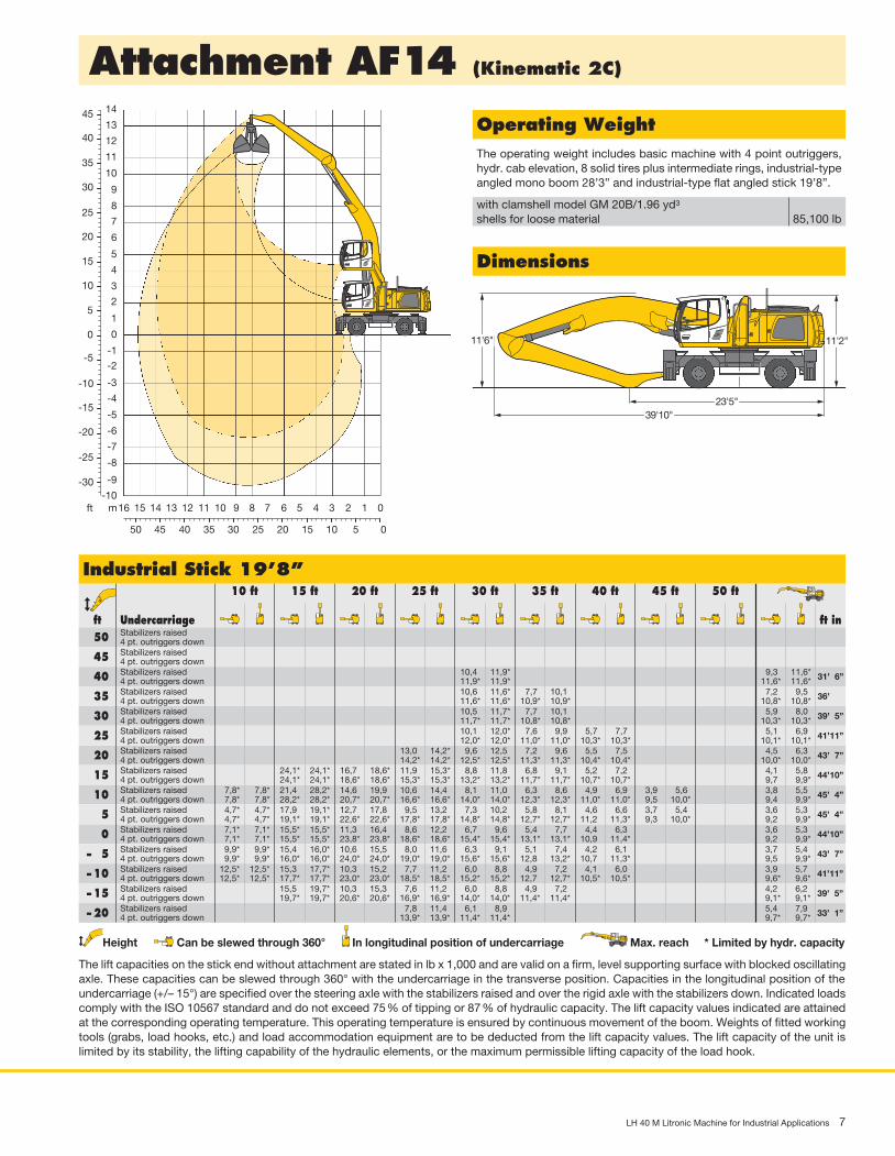
Operating�WeightThe operating weight includes basic machine with 4 point outriggers, hydr. cab elevation, 8 solid tires plus intermediate rings, industrial-type angled mono boom 28’3” and industrial-type flat angled stick 19’8”.
with clamshell model GM 20B/1.96 yd3
shells for loose material 85,100 lb
Height Can be slewed through 360° In longitudinal position of undercarriage Max. reach * Limited by hydr. capacity
The lift capacities on the stick end without attachment are stated in lb x 1,000 and are valid on a firm, level supporting surface with blocked oscillating axle. These capacities can be slewed through 360° with the undercarriage in the transverse position. Capacities in the longitudinal position of the undercarriage (+/– 15°) are specified over the steering axle with the stabilizers raised and over the rigid axle with the stabilizers down. Indicated loads comply with the ISO 10567 standard and do not exceed 75 % of tipping or 87 % of hydraulic capacity. The lift capacity values indicated are attained at the corresponding operating temperature. This operating temperature is ensured by continuous movement of the boom. Weights of fitted working tools (grabs, load hooks, etc.) and load accommodation equipment are to be deducted from the lift capacity values. The lift capacity of the unit is limited by its stability, the lifting capability of the hydraulic elements, or the maximum permissible lifting capacity of the load hook.
� ft� Undercarriage� � � � � � � � � � ft�in Stabilizers raised 50 4 pt. outriggers down Stabilizers raised 45 4 pt. outriggers down Stabilizers raised 40 4 pt. outriggers down Stabilizers raised 35 4 pt. outriggers down Stabilizers raised 30 4 pt. outriggers down Stabilizers raised 25 4 pt. outriggers down Stabilizers raised 20 4 pt. outriggers down Stabilizers raised 15 4 pt. outriggers down Stabilizers raised 10 4 pt. outriggers down Stabilizers raised 5 4 pt. outriggers down Stabilizers raised 0 4 pt. outriggers down Stabilizers raised –�� 5 4 pt. outriggers down Stabilizers raised –�10 4 pt. outriggers down Stabilizers raised –�15 4 pt. outriggers down Stabilizers raised –�20 4 pt. outriggers down
8 LH 40 M Litronic Machine for Industrial Applications
Attachment�GA14�(Kinematic�2A)
45
50
55
40
35
30
25
20
15
10
5
0
-5
-10
-15
-20
8
9
10
11
12
13
14
15
16
17US_H0268
4550 40 35 30 25 20 15 10 5 0
141516 13 12 11 10 9 8 7 6 5 4 3 2 1 0
7
6
5
4
3
2
1
0
-1
-2
-3
-4
-5
-6
-7mft
11'2"
24'3"39'10"
9'4"
H0269
Dimensions
Operating�WeightThe operating weight includes basic machine with 4 point outriggers, hydr. cab elevation, 8 solid tires plus intermediate rings, industrial-type straight mono boom 28’3” and industrial-type angled stick 19’8”.
with grapple model GM 70C/1.05 yd3 semi-closed tines 84,900 lb
Height Can be slewed through 360° In longitudinal position of undercarriage Max. reach * Limited by hydr. capacity
The lift capacities on the stick end without attachment are stated in lb x 1,000 and are valid on a firm, level supporting surface with blocked oscillating axle. These capacities can be slewed through 360° with the undercarriage in the transverse position. Capacities in the longitudinal position of the undercarriage (+/– 15°) are specified over the steering axle with the stabilizers raised and over the rigid axle with the stabilizers down. Indicated loads comply with the ISO 10567 standard and do not exceed 75 % of tipping or 87 % of hydraulic capacity. The lift capacity values indicated are attained at the corresponding operating temperature. This operating temperature is ensured by continuous movement of the boom. Weights of fitted working tools (grabs, load hooks, etc.) and load accommodation equipment are to be deducted from the lift capacity values. The lift capacity of the unit is limited by its stability, the lifting capability of the hydraulic elements, or the maximum permissible lifting capacity of the load hook.
� ft� Undercarriage� � � � � � � � � � ft�in Stabilizers raised 50 4 pt. outriggers down Stabilizers raised 45 4 pt. outriggers down Stabilizers raised 40 4 pt. outriggers down Stabilizers raised 35 4 pt. outriggers down Stabilizers raised 30 4 pt. outriggers down Stabilizers raised 25 4 pt. outriggers down Stabilizers raised 20 4 pt. outriggers down Stabilizers raised 15 4 pt. outriggers down Stabilizers raised 10 4 pt. outriggers down Stabilizers raised 5 4 pt. outriggers down Stabilizers raised 0 4 pt. outriggers down Stabilizers raised –�� 5 4 pt. outriggers down Stabilizers raised –�10 4 pt. outriggers down Stabilizers raised –�15 4 pt. outriggers down Stabilizers raised –�20 4 pt. outriggers down
LH 40 M Litronic Machine for Industrial Applications 9
Attachment�AF15�(Kinematic�2D)
55
50
45
40
35
30
25
20
15
10
5
0
-5
-10
-15
-20
-25
-30
89
1011121314151617 US_H0264
17
55 50 45 40 35 30 25 20 15 10 5 0
16 15 14 13 12 11 10 9 8 7 6 5 4 3 2 1 0
76543210
-1-2-3-4-5-6
-8-7
-9-10
mft
11'2"
39'6"
US_H0265
25'11"
3'3"
3'7"
10'4"
Dimensions
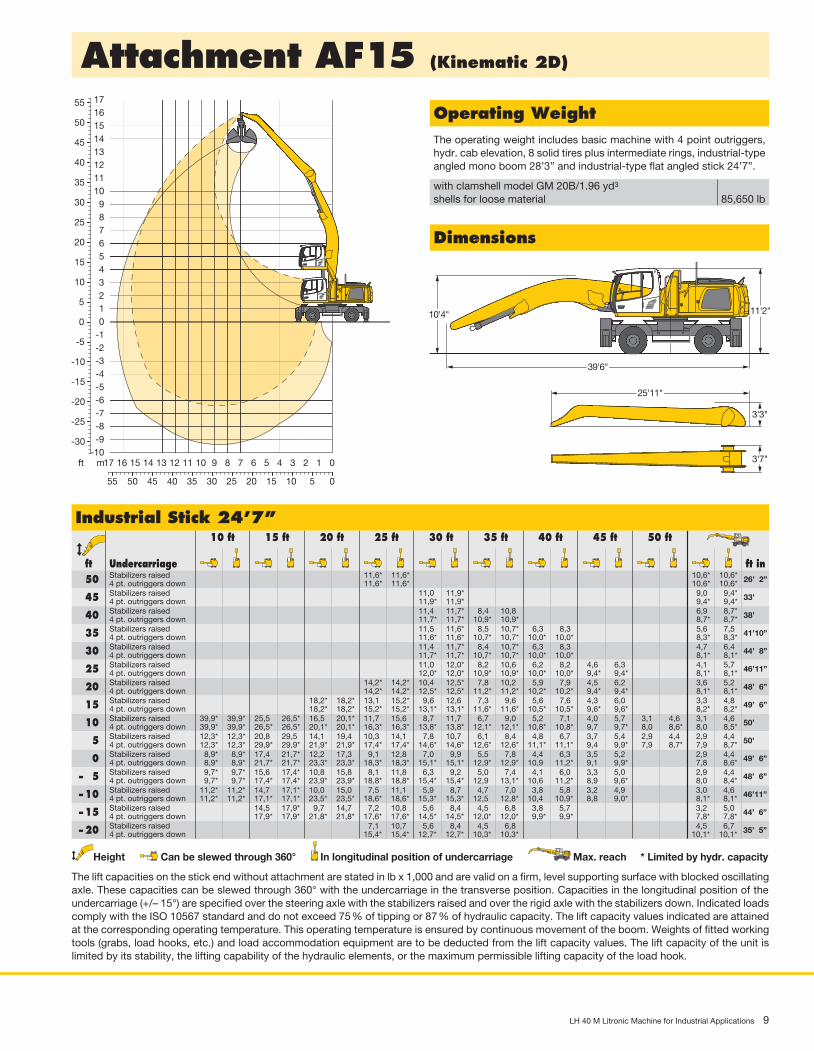
Operating�WeightThe operating weight includes basic machine with 4 point outriggers, hydr. cab elevation, 8 solid tires plus intermediate rings, industrial-type angled mono boom 28’3” and industrial-type flat angled stick 24’7”.
with clamshell model GM 20B/1.96 yd3
shells for loose material 85,650 lb
Height Can be slewed through 360° In longitudinal position of undercarriage Max. reach * Limited by hydr. capacity
The lift capacities on the stick end without attachment are stated in lb x 1,000 and are valid on a firm, level supporting surface with blocked oscillating axle. These capacities can be slewed through 360° with the undercarriage in the transverse position. Capacities in the longitudinal position of the undercarriage (+/– 15°) are specified over the steering axle with the stabilizers raised and over the rigid axle with the stabilizers down. Indicated loads comply with the ISO 10567 standard and do not exceed 75 % of tipping or 87 % of hydraulic capacity. The lift capacity values indicated are attained at the corresponding operating temperature. This operating temperature is ensured by continuous movement of the boom. Weights of fitted working tools (grabs, load hooks, etc.) and load accommodation equipment are to be deducted from the lift capacity values. The lift capacity of the unit is limited by its stability, the lifting capability of the hydraulic elements, or the maximum permissible lifting capacity of the load hook.
� ft� Undercarriage� � � � � � � � � � ft�in Stabilizers raised 50 4 pt. outriggers down Stabilizers raised 45 4 pt. outriggers down Stabilizers raised 40 4 pt. outriggers down Stabilizers raised 35 4 pt. outriggers down Stabilizers raised 30 4 pt. outriggers down Stabilizers raised 25 4 pt. outriggers down Stabilizers raised 20 4 pt. outriggers down Stabilizers raised 15 4 pt. outriggers down Stabilizers raised 10 4 pt. outriggers down Stabilizers raised 5 4 pt. outriggers down Stabilizers raised 0 4 pt. outriggers down Stabilizers raised –�� 5 4 pt. outriggers down Stabilizers raised –�10 4 pt. outriggers down Stabilizers raised –�15 4 pt. outriggers down Stabilizers raised –�20 4 pt. outriggers down
10 LH 40 M Litronic Machine for Industrial Applications
Attachment�AF15�(Kinematic�2C)
45
40
35
30
25
20
15
10
5
0
-5
-10
-15
-20
-25
-30
-35
US_H0276
17
55 50 45 40 35 30 25 20 15 10 5 0
16 15 14 13 12 11 10 9 8 7 6 5 4 3 2 1 0mft
89
101112131415
76543210
-1-2-3-4-5-6
-8-7
-9-10-11
11'2"
38'11"
H0277
25'11"
3'3"
3'7"
9'
Dimensions
Operating�WeightThe operating weight includes basic machine with 4 point outriggers, hydr. cab elevation, 8 solid tires plus intermediate rings, industrial-type angled mono boom 28’3” and industrial-type flat angled stick 24’7”.
with clamshell model GM 20B/1.96 yd3
shells for loose material 85,650 lb
Height Can be slewed through 360° In longitudinal position of undercarriage Max. reach * Limited by hydr. capacity
The lift capacities on the stick end without attachment are stated in lb x 1,000 and are valid on a firm, level supporting surface with blocked oscillating axle. These capacities can be slewed through 360° with the undercarriage in the transverse position. Capacities in the longitudinal position of the undercarriage (+/– 15°) are specified over the steering axle with the stabilizers raised and over the rigid axle with the stabilizers down. Indicated loads comply with the ISO 10567 standard and do not exceed 75 % of tipping or 87 % of hydraulic capacity. The lift capacity values indicated are attained at the corresponding operating temperature. This operating temperature is ensured by continuous movement of the boom. Weights of fitted working tools (grabs, load hooks, etc.) and load accommodation equipment are to be deducted from the lift capacity values. The lift capacity of the unit is limited by its stability, the lifting capability of the hydraulic elements, or the maximum permissible lifting capacity of the load hook.
� ft� Undercarriage� � � � � � � � � � ft�in Stabilizers raised 45 4 pt. outriggers down Stabilizers raised 40 4 pt. outriggers down Stabilizers raised 35 4 pt. outriggers down Stabilizers raised 30 4 pt. outriggers down Stabilizers raised 25 4 pt. outriggers down Stabilizers raised 20 4 pt. outriggers down Stabilizers raised 15 4 pt. outriggers down Stabilizers raised 10 4 pt. outriggers down Stabilizers raised 5 4 pt. outriggers down Stabilizers raised 0 4 pt. outriggers down Stabilizers raised –�� 5 4 pt. outriggers down Stabilizers raised –�10 4 pt. outriggers down Stabilizers raised –�15 4 pt. outriggers down Stabilizers raised –�20 4 pt. outriggers down Stabilizers raised –�25 4 pt. outriggers down
LH 40 M Litronic Machine for Industrial Applications 11
Attachment�GA16�(Kinematic�2A)
45
50
55
40
35
30
25
20
15
10
5
0
-5
-10
-15
-20
-25
8
9
1011
121314
15
16
1718
US_H0272
455055 40 35 30 25 20 15 10 5 0
14151617 13 12 11 10 9 8 7 6 5 4 3 2 1 0
7
65
43
21
0
-1-2
-3
-4-5-6-7-8mft
11'2"
23'11"41'6"
11'2"
H0273
Dimensions
Operating�WeightThe operating weight includes basic machine with 4 point outriggers, hydr. cab elevation, 8 solid tires plus intermediate rings, industrial-type straight mono boom 29’10” and industrial-type angled stick 22’4”.
with grapple model GM 65/0.78 yd3 semi-closed tines 84,900 lb
Height Can be slewed through 360° In longitudinal position of undercarriage Max. reach * Limited by hydr. capacity
The lift capacities on the stick end without attachment are stated in lb x 1,000 and are valid on a firm, level supporting surface with blocked oscillating axle. These capacities can be slewed through 360° with the undercarriage in the transverse position. Capacities in the longitudinal position of the undercarriage (+/– 15°) are specified over the steering axle with the stabilizers raised and over the rigid axle with the stabilizers down. Indicated loads comply with the ISO 10567 standard and do not exceed 75 % of tipping or 87 % of hydraulic capacity. The lift capacity values indicated are attained at the corresponding operating temperature. This operating temperature is ensured by continuous movement of the boom. Weights of fitted working tools (grabs, load hooks, etc.) and load accommodation equipment are to be deducted from the lift capacity values. The lift capacity of the unit is limited by its stability, the lifting capability of the hydraulic elements, or the maximum permissible lifting capacity of the load hook.
� ft� Undercarriage� � � � � � � � � � ft�in Stabilizers raised 55 4 pt. outriggers down Stabilizers raised 50 4 pt. outriggers down Stabilizers raised 45 4 pt. outriggers down Stabilizers raised 40 4 pt. outriggers down Stabilizers raised 35 4 pt. outriggers down Stabilizers raised 30 4 pt. outriggers down Stabilizers raised 25 4 pt. outriggers down Stabilizers raised 20 4 pt. outriggers down Stabilizers raised 15 4 pt. outriggers down Stabilizers raised 10 4 pt. outriggers down Stabilizers raised 5 4 pt. outriggers down Stabilizers raised 0 4 pt. outriggers down Stabilizers raised –�� 5 4 pt. outriggers down Stabilizers raised –�10 4 pt. outriggers down Stabilizers raised –�15 4 pt. outriggers down
12 LH 40 M Litronic Machine for Industrial Applications
Hole D
Energy recovery with kinematic variant 2C
Hole 2
2C
Hole D
Energy recovery with kinematic variant 2D
Hole 2
2D
2D 2C
US_H0280
Hole A
Energy recovery with kinematic variant 2A
Hole B
2A
Kinematic�Variant�2A
Kinematic�Variant�2D/2C
Kinematic�Variants
Altered range curve with additional reach depth, e.g. for unloading from ships
Shells�for�Loose�Material
with with with with ribbed perforated ribbed perforated shells shells shells shells
LH 40 M Litronic Machine for Industrial Applications 13
Variety�of�Tools
Shells for loose material with cutting edge (without teeth)Clamshell�Model�GM�20BCutting width of shells ft in 3’3” 3’11” 5’3”Capacity yd3 1.70 1.96 2.62For loose material, specific weight up to lb/yd3 2,528 2,528 2,528Weight lb 2,987 3,120 3,417
Multiple�Tine�Grapples� open tines semi-closed tines closed tines
Crane�Hook�with�SuspensionMax. load lb 27,558Height with suspension ft in 3’1”Weight lb 212
Magnet�Devices/Lifting�MagnetsGenerator kW 20 30Electromagnets�with�SuspensionPower kW 8.5/10 10.4/11.7Diameter of magnet ft in 4’5” 4’11”Weight lb 3,748 5,291
Wood�GrappleGrapple�Model�GM�20BClaw width ft in 2’8” 2’8” 2’8” 2’8”Size in2 2,015 2,325 2,635 2,945Height of grapple, closed ft in 9’8” 9’10” 10’ 10’4”Weight lb 3,693 3,803 3,913 4,211
Sorting�GrappleGrapple�Model�SG�30Cutting width of shells ft in 3’3” 3’3” 3’9” 3’9”Capacity yd3 0.98 1.11 1.18 1.31Max. closing force lb 17,640 17,640 17,640 17,640Weight incl. adapter plate lb 3,595 3,550 3,770 3,725
14 LH 40 M Litronic Machine for Industrial Applications
B
B
A
A
System power
The energy recovery cylinder is a storage system which is independ-ent of the diesel engine. The system performance of material handling machines fitted with the ERC system is composed of the installed engine power and the energy recovery cylinder. When the equipment is raised, energy from the ERC system is supplied in addition to the power from the diesel engine.
1. Attachment fitting raised / Energy released
2. Lower attachment fitting / Store energy 4. Raise attachment fitting / Release energy
3. Attachment fitting lowered / Energy stored
Po
wer
[kW
]
Boom position
Engine powerERC performance
System performance
System power
Engine ERC
• fuel savings of up to 30 %
• lower running costs
• reduced pollutant and noise emissions
• increased overall power
ERC-System
ERC System – More performance, less consumption
Liebherr ERC-System
Lowering the equipment stores energy in the ERC system. This stored energy is then made available to the machine to provide additional engine power. When the equipment is raised the stored energy is released and is reflected in powerful, homogeneous operating cycles. The result is a clear saving on fuel – and, at the same time, even greater performance.
Efficiencyas standard
LH 40 M Litronic Machine for Industrial Applications 15
Equipment
�•�=�Standard,�+�=�Option* = optionally extendable after one year
UndercarriageSupport rocker, variants +Individual control outriggers +Shuttle axle lock, automatic •Dozer blade +Outrigger monitoring system +Tyres, variants +Protection for travel drive +Protection for piston rods, outriggers +Tool equipment, extended •Two lockable storage boxes •
Electric cooler +LiDAT Plus (extended Liebherr data transfer system) * •Bullet proof glass +Positioning swing brake +Proportional control +Radio Comfort (control via display) +Preparation for radio installation •Back-up alarm (acoustic signal is emitted traveling backward, can not be switched off) +Warning beacon on cab +Windscreen wiper, roof +Top guard +Front guard +Sun visor +Auxiliary heating, adjustable (week time switch) +Flashing light (xenon) +Electronic immobilizer +
Operator’s�CabCab lights rear, halogen +Cab lights rear, LED 1300 lumen +Cab lights front, halogen •Cab lights front, LED 1300 lumen +Operator’s seat Standard •Operator’s seat Comfort +Operator’s seat Premium +Driving alarm (acoustic signal is emitted during travel, can be switched ON/OFF) +Fire extinguisher +Joystick steering +Cab elevation, hydraulic (LHC) +Cab elevation, rigid (LFC) +Automatic air conditioning •
AttachmentBoom lights, 2 pieces, halogen •Boom lights, 2 pieces, LED 1300 lumen +Stick lights, 2 pieces, halogen •Stick lights, 2 pieces, LED 1300 lumen, with protection +Boom shutoff, ascending +AutoLift +ERC system •Height limitation and stick shutoff, electronically +Boom cylinder cushioning +Industrial stick with quick coupling +Stick camera (with separate monitor), bottom side, with protection +Liebherr lightweight stick +Liebherr multi coupling system +Liebherr quick coupler, hydraulic or mechanical +Pipe fracture safety valves hoist cylinders •Pipe fracture safety valve stick cylinder •Quick coupling system LIKUFIX +Quick coupling system MH40/MH110 +Protection for piston rod, ERC +Protection for piston rod, hoist cylinder +Retract stick without pressure •Overload warning device +Protection for stick +
UppercarriageRefuelling system with filling pump +Railing on uppercarriage +Generator +Main battery switch for electrical system •Protection for headlights +Protection for rear lights +
HydraulicsElectronic pump regulation •Liebherr hydraulic oil from – 4 °F to + 104 °F •Liebherr hydraulic oil, biologically degradable +Magnetic rod in hydraulic tank •Bypass filter +Preheating hydraulic oil +
EngineFuel anti-theft device +Liebherr particle filter •Reversible fan drive, fully automatic +Air pre-filter with dust discharge +Protective grid in front of cooler intake •Preheating fuel +Preheating coolant +Preheating engine oil +
Complete�MachineLubrication
Lubrication undercarriage, manually – decentralized (grease points) •Central lubrication system for uppercarriage and attachment, automatically •Central lubrication system for undercarriage, automatically +
Special coatingSingle-coloured, grey parts excepted +Single-coloured, grey parts included (except power train) +Multicoloured (except power train) +
MonitoringRear view monitoring with camera •Side view monitoring with camera +
The Liebherr Group of Companies
Wide Product RangeThe Liebherr Group is one of the largest construction equipment manufacturers in the world. Liebherr’s high-value products and services enjoy a high reputation in many other fields. The wide range includes domestic appliances, aerospace and transportation systems, machine tools and maritime cranes.
Exceptional Customer BenefitEvery product line provides a complete range of models in many different versions. With both their technical excel lence and acknowledged quality, Liebherr products offer a maximum of customer benefits in practical application.
State-of-the-art TechnologyTo provide consistent, top quality products, Liebherr attaches great importance to each product area, its components and core technologies. Important modules and components are developed and manufactured in-house, for instance the entire drive and control techno logy for construction equipment and mining trucks.
Worldwide and IndependentHans Liebherr founded the Liebherr family company in 1949. Since that time, the enterprise has steadily grown to a group of more than 130 companies with over 38,000 employees located on all continents. The corporate headquarters of the Group is Liebherr-International AG in Bulle, Switzerland. The Liebherr family is the sole owner of the company.
www.liebherr.us
Liebherr Construction Equipment Co.4100 Chestnut Avenue, Newport News, VA 23607, USA +1 (757) 245 5251, Fax +1 (757) 928 8701www.liebherr.us, E-Mail: [email protected] www.facebook.com/LiebherrConstruction