Page 1
3.5in [89mm]
(Recommended)
134in3402mm
Max Operating
Depth
163in4144mm
Max Operating Width
36in914mm
Electrical DoorMin Clearance
14.0in356mm
Pneumatic Door
Access
122in3096mm
MaxOperating
Height
151in3832mm
122in3099mm
27in690mm
Chip ChuteDischarge
All dimensions based on stackup of sheetmetal, subject to variation of 1/2" ( 13 mm)
VF-3 / VF-3SS Installation DimensionsMachine Layout DrawingRevision 1Page 1 of 61-OCT-2019
*Due to continual product improvements, machine dimensions are subject to change without notice.
Page 2
83in2120mmPower In
42in1065mmPower In
29in746mmAir In
4in107mmAir In
13in337mmAir In
(Measured fromback of casting)
8.7in221mm
Power In(Measured fromback of casting)
48.1in1222mm
48.1in1222mm
35.1in891mm
40.9in1038mm
71.5in1817mm
38.0in965mm
(Ref)
24.2in615mm
(Ref)
38.0in965mm
(Ref)
8.1in205mm
(Ref)
1.5in[ 38mm]
8.5in[ 220mm]
Anchor Hole Detail
All dimensions based on stackup of sheetmetal, subject to variation of 1/2" ( 13 mm)
Back View Right View
**Note: Anchor hole locations will be changing on VF/VM series machines in 2019.
Before drilling any anchor holes, please email the Haas Products Group to confirm the pattern is correct for your exact machine [email protected]
VF-3 / VF-3SS Utilities & AnchoringMachine Layout DrawingRevision 1Page 2 of 61-OCT-2019
Anchor Pattern**
Air & Power
*Due to continual product improvements, machine dimensions are subject to change without notice.
Page 3
122in3108mm
Max Operating
Height
28in701mm
Chip Chute Discharge
98in2479mm
30 Pocket40 Taper
Side Mounted Tool Changer
81in2045mm
37.5in[952mm]
Table Height
93in2374mm
32in817mm
25in632mm
111in2819mm
50 Pocket40 Taper
Side Mounted Tool Changer
104in2640mm
36in918mm
27.9in708mm
151in3833mm
124in3151mm
36in915mm
14in358mm
13.3in339mm
10.3in261mm
18.0in
457mm
All dimensions based on stackup of sheetmetal, subject to variation of 1/2" ( 13 mm)
All dimensions based on stackup of sheetmetal, subject to variation of 1/2" ( 13 mm)
VF3/SS As Shipped Height
40 Taper 30-SMTC 94.5in [2400mm]
40 Taper 50-SMTC Domestic 121.5in [3086mm]Export 94.5in [2400mm]
VF-3 / VF-3SS BreakdownsMachine Layout DrawingRevision 1Page 3 of 61-OCT-2019
Width Breakdown
Height Breakdown
*Due to continual product improvements, machine dimensions are subject to change without notice.
Page 4
4.2in107mm
Min Z Clearance**
29.2in742mm
Max Z Clearance**
25.0in635mm
Z Axis Travel
40.0in1016mm
X Axis Travel
20.0in508mm
Y Axis Travel
16.6in422mm
9.5in242mm
1.0in25mm
16.6in421mm
.7in17mm
3.2in81mm
Table at Home Position
**Note: Add 3.0" [76mm] to Z Axis clearance if Extended Z Clearance option is purchased
Axis TravelX 40in 1016mmY 20in 508mmZ 25in 635mm
VF-3 / VF-3SS Axes ClearancesMachine Layout DrawingRevision 1Page 4 of 61-OCT-2019
Z-Axis Clearance
X&Y-Axis Clearance
*Due to continual product improvements, machine dimensions are subject to change without notice.
Page 5
.63in16.0mm
.42in10.7mm
1.06in26.9mm
1.06in26.9mm
18.0in457mm
44.0in1118mm
3.937in100.0mm
(Typ)
3.937in100.0mm
(Typ)
1.13in28.6mm
2.31in58.8mm
Phantom holes are used for table mounting and cannot be used for part fixturing (24x)
M12x1.75 25mm
(55x)
18.0in457mm
44.0in1118mm
2.750in69.9mm
(Typ)
3.150in80.0mm
(Typ)
2.70in68.6mm
2.75in
69.8mm
Phantom holes are used for table mounting and cannot be used for part fixturing (24x)
1/2-13 UNC1.0"
(75x)
18.3in465mmUsableTable
47.7in1211mm
Usable table
3.150in80.0mm
CL to CL (4x)
Standard T Slot Table
Metric Low Profile Table (76mm Extended Z Clearance)
Inch Low Profile Table (3.0" Extended Z Clearance)
T Slot Detail
VF-3 / VF-3SS Table DetailMachine Layout DrawingRevision 1Page 5 of 61-OCT-2019
*Due to continual product improvements, machine dimensions are subject to change without notice.
Page 6
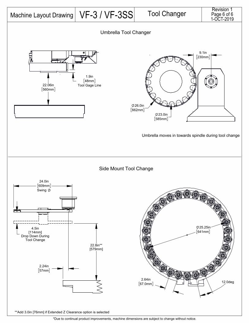
2.24in57mm
4.5in[114mm]
Drop Down DuringTool Change
22.8in**[579mm]
24.0in609mm
Swing
Side Mount Tool Change
**Add 3.0in [76mm] if Extended Z Clearance option is selected
2.64in67.0mm
25.25in641mm
12.0deg
22.06in560mm
1.9in48mm
Tool Gage Line
9.1in230mm
26.0in662mm
23.0in585mm
Umbrella Tool Changer
Umbrella moves in towards spindle during tool change
VF-3 / VF-3SS Tool ChangerMachine Layout DrawingRevision 1Page 6 of 61-OCT-2019
*Due to continual product improvements, machine dimensions are subject to change without notice.