23
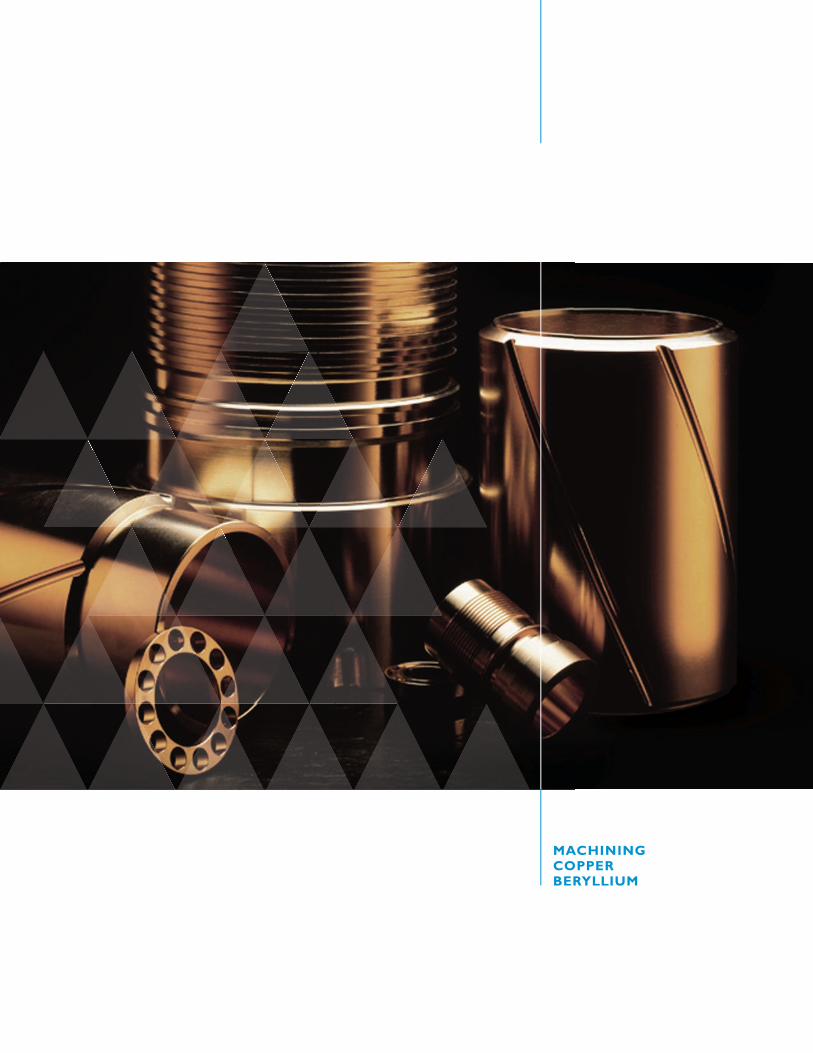
MACHINING COPPER BERYLLIUM
| Date post: | 10-Mar-2018 |
| Category: |
Documents |
| Upload: | phungtuyen |
| View: | 223 times |
| Download: | 0 times |
machInInG copper BeryllIum
performanceMACHINING
MACHINING Copper beryllIuM
Brush Peformance Alloysrush Peformance Alloysrush Peformance Alloysrush Peformance Alloysrush Peformance Alloysrush Peformance Alloys
list of Tables and figures ...................................................................................... 2
Introduction ....................................................................................................................... 3
copper Beryllium alloys ........................................................................................ 4
alloy Temper ..................................................................................................................... 5
Tool materials and coolants .............................................................................. 6
safe handling of copper Beryllium ............................................................ 7............................................................ 7
sawing copper Beryllium .................................................................................... 8.................................................................................... 8
Turning copper Beryllium ................................................................................... 9................................................................................... 9
Drilling copper Beryllium ................................................................................ 10................................................................................ 10................................................................................ 10................................................................................ 10
Tapping copper Beryllium ............................................................................... 11............................................................................... 11............................................................................... 11............................................................................... 11............................................................................... 11
reaming copper Beryllium ............................................................................. 12............................................................................. 12............................................................................. 12
milling copper Beryllium .................................................................................. 13.................................................................................. 13.................................................................................. 13.................................................................................. 13
Grinding copper Beryllium ............................................................................. 14............................................................................. 14............................................................................. 14............................................................................. 14............................................................................. 14............................................................................. 14
electrical Discharge machining copper Beryllium ................... 15................... 15
appendix a ...................................................................................................................... 16...................................................................................................................... 16...................................................................................................................... 16...................................................................................................................... 16...................................................................................................................... 16
appendix B ...................................................................................................................... 18...................................................................................................................... 18...................................................................................................................... 18...................................................................................................................... 18
scrap Generated from machining ............................................................. 20............................................................. 20............................................................. 20............................................................. 20
TAble of CoNTeNTs
performance
MACHINING Copper beryllIuM
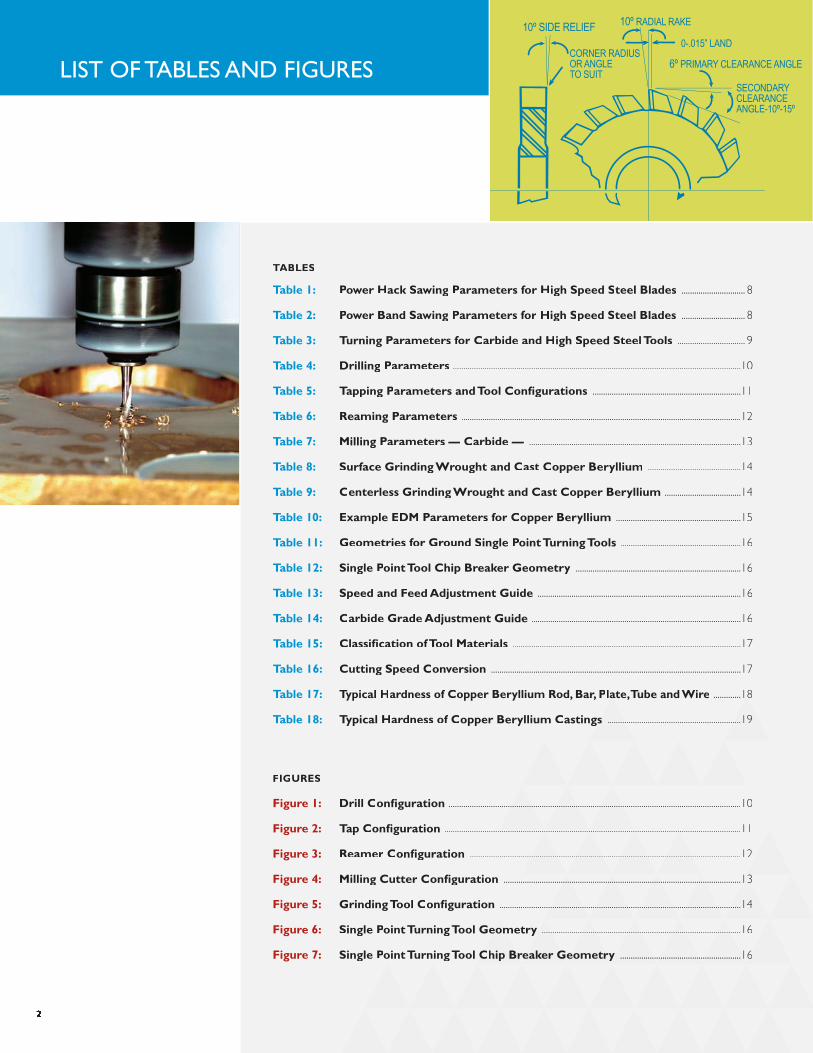
10º SIDE RELIEF
CORNER RADIUSOR ANGLETO SUIT
10º RADIAL RAKE
SECONDARYCLEARANCEANGLE-10º-15º
0-.015” LAND
6º PRIMARY CLEARANCE ANGLE
2
lIsT of TAbles ANd fIGures
TaTaT Bles
Table 1: power hack sawing parameters for high speed steel Blades .............................. 8
Table 2: power Band sawing parameters for high speed steel Blades .............................. 8
Table 3: Turning parameters for carbide and high speed steel Tools ................................ 9
Table 4: Drilling parameters ........................................................................................................................................10
Table 5: Tapping parameters and Tool configurations ......................................................................11
Table 6: reaming parameters ....................................................................................................................................12
Table 7: milling parameters — carbide — ....................................................................................................13
Table 8: surface Grinding Wrought and cast copper Beryllium ............................................14
Table 9: centerless Grinding Wrought and cast copper Beryllium ....................................14
Table 10: example eDm parameters for copper Beryllium ...........................................................15
Table 11: Geometries for Ground single point Turning Tools .........................................................16
Table 12: single point Tool chip Breaker Geometry ..............................................................................16
Table 13: speed and feed adjustment Guide ................................................................................................16
Table 14: carbide Grade adjustment Guide ...................................................................................................16
Table 15: classification of Tool materials ............................................................................................................17
Table 16: cutting speed conversion ......................................................................................................................17
Table 17: Typical hardness of copper Beryllium rod, Bar, plate, Tube and Wirelate,Tube and Wire .............18.............18
Table 18: Typical hardness of copper Beryllium castings astings ...............................................................19...............................................................19...............................................................19
fIGures
figure 1: Drill configuration ........................................................................................................................................................................................................................................................................................................................................................................................................................................................................................................................................................................10
figure 2: Tap configuration ............................................................................................................................................................................................................................................................................................................................................................................................................................................................................................................................................................................................................................................................................................................................11
figure 3: reamer configuration ................................................................................................................................................................................................................................................................................................................................................................................................................................................................................................................................................................................................................................................................12
figure 4: milling cutter configuration ................................................................................................................13................................................................................................................13................................................................................................................13................................................................................................................13................................................................................................................13................................................................................................................13
figure 5: Grinding Tool configuration ..................................................................................................................14..................................................................................................................14..................................................................................................................14..................................................................................................................14..................................................................................................................14..................................................................................................................14
figure 6: single point Turning Tool Geometryoint Turning Tool Geometryoint Turning Tool Geometry ..............................................................................................16..............................................................................................16..............................................................................................16..............................................................................................16..............................................................................................16..............................................................................................16
figure 7: single point Turning Tool cchip Breaker Geometry hip Breaker Geometry hip Breaker Geometry hip Breaker Geometry hip Breaker Geometry .........................................................16.........................................................16.........................................................16.........................................................16.........................................................16

Copper beryllium alloys are often the
material of choice in applications spanning the
automotive, aerospace, electronics,
electromechanical, computer,
telecommunications, oil & gas, appliance and
medical industries. The popularity of these
high reliability engineered materials stems
from their combination of high conductivity
and mechanical strength, excellent wear and
corrosion resistance, nonmagnetic
characteristics, high fatigue strength and
hardness, and their ability to be worked in a
soft condition and then hardened by a
simple heat treatment.
The machining characteristics of copper
beryllium alloys are a function of a given
alloy’s temper and form. This report furnishes
the information most needed by shops
performing the usual machining operations.
In doing so, it summarizes current
machinability data as developed by Brush
Performance Alloys and verified by a number
of users with extensive experience in the
machining of these materials.
It is important to note that machinability is
not actually defined in this brochure and the
various alloys and conditions are not rated
according to any machinability index. After
all, it is the number of machined parts per
hour (determined partly by the machining
speeds and feeds) which determines the
economics of the machining operation.
The machinability of a given material is
ultimately a function of these factors,
additional considerations such as part
configuration, dimensional tolerances, the
required surface finish and the skill of the
machine tool operator.
The machining and tool recommendations
are provided as a guide to the machinist
working with copper beryllium alloys. These
recommendations provide a starting point
for each machining operation. Advances in
machine tools, tooling materials, tool coatings
and cutting fluids may require some changes
in machining parameters. Machining methods
also may need to be adjusted for individual
part geometry.
3
INTroduCTIoN
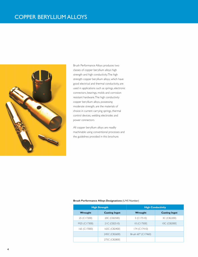
high strength high conductivity
Wrought casting Ingot Wrought casting Ingot
25 (C17200) 20C (C82500)25 (C17200) 20C (C82500) 3 (C17510) 3C (C82200)
M25 (C17300) 21C (C82510)M25 (C17300) 21C (C82510) 10 (C17500) 10C (C82000)
165 (C17000) 165C (C82400)165 (C17000) 165C (C82400) 174 (C17410)
245C (C82600) Brush 60245C (C82600) Brush 60® (C17460)
275C (C82800)
Brush performance alloys Designations (uNs Number)
Copper beryllIuM Alloys
Brush Performance Alloys produces two
classes of copper beryllium alloys: high
strength and high conductivity. The high
strength copper beryllium alloys, which have
good electrical and thermal conductivity, are
used in applications such as springs, electronic
connectors, bearings, molds and corrosion
resistant hardware. The high conductivity
copper beryllium alloys, possessing
moderate strength, are the materials of
choice in current carrying springs, thermal
control devices, welding electrodes and
power connectors.
All copper beryllium alloys are readily
machinable using conventional processes and
the guidelines provided in this brochure.
4
Brush Designation(ASTM DESIGNATION)
Description
Wrought products
a (TB00) Solution annealed. Softest temper.
½ h (TD02) Solution annealed and moderately cold-worked
h (TD04) Solution annealed and fully cold-worked
aT (TaT (Ta f00)2 Precipitation hardened A temper
½ hT (Th02)2 Precipitation hardened ½ H temper
hT (Th04)2 Precipitation hardened H temper. Hardest temper.
cast products
c (m01/m03) As cast (sand/investment). Slightly harder than annealed temper.
cT (o11)2 Cast and precipitation hardened. Moderately hard.
a (TB00) Solution annealed
aT (TaT (Ta f00)2 Solution annealed and precipitation hardened. Hardest cast temper.
Copper beryllium alloys derive their high
strength through heat treatment and, in the
case of small cross section wrought forms,
cold working. The amount of cold work and
the type of heat treatment determine the
alloy’s properties. The combination of cold
work and heat treatment define the alloy’s
temper. A brief definition of the temper
designations is provided below.
Brush Performance Alloys supplies wrought
products in either age hardenable or mill
hardened tempers. The age hardenable
tempers (e.g. , A, ½ H and H) require heat
treatment to produce the alloy’s maximum
strength and conductivity. The mill hardened
tempers are heat treated before they leave
the supplier. The specific machining operation
and application requirements determine
if the alloy is machined before or after
heat treating.
The solution annealed temper (A) contains
no cold work and is the softest temper.
Adding cold work raises the alloy’s hardness,
but is limited to forms with cross sections
typically less than 2 inches and is performed
by the mill. Precipitation heat treatment
further increases hardness of annealed and
cold-worked tempers.
The heat treatment (age hardening) of the
high strength, copper beryllium alloys is
accompanied by a slight volume change.
These alloys shrink about 0.5 volumetric
percent. Where precise dimensional control
is required, final machining should follow
heat treatment. Rough machining can be
done before heat treating, but due to the
excellent machinability of high strength
copper beryllium alloys, it is recommended
that the material be purchased and machined
in the age hardened condition.*
The high conductivity copper beryllium
alloys are usually purchased in mill hardened
tempers and are readily machinable because
of their moderate hardness levels. There
is no significant volume change during the
heat treatment of the high conductivity alloys.
Alloy TeMper
*Rod and bar smaller than 7/16 inch in cross section may not be available in age hardened, straight, long lengths.
Temper Designations
1 Appendix B lists the hardness ranges for each of the copper beryllium tempers.2 The T designation indicates the alloy is heat treated after annealing or cold working. These are the hardest tempers.
5
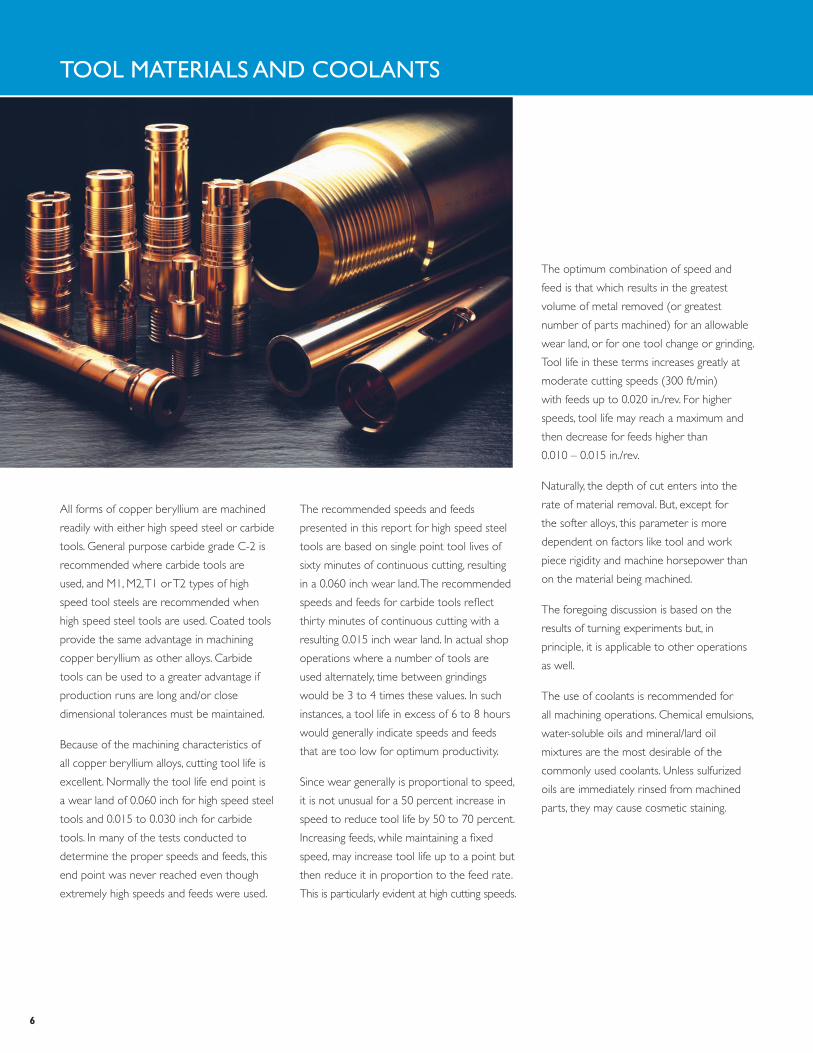
All forms of copper beryllium are machined
readily with either high speed steel or carbide
tools. General purpose carbide grade C-2 is
recommended where carbide tools are
used, and M1, M2, T1 or T2 types of high
speed tool steels are recommended when
high speed steel tools are used. Coated tools
provide the same advantage in machining
copper beryllium as other alloys. Carbide
tools can be used to a greater advantage if
production runs are long and/or close
dimensional tolerances must be maintained.
Because of the machining characteristics of
all copper beryllium alloys, cutting tool life is
excellent. Normally the tool life end point is
a wear land of 0.060 inch for high speed steel
tools and 0.015 to 0.030 inch for carbide
tools. In many of the tests conducted to
determine the proper speeds and feeds, this
end point was never reached even though
extremely high speeds and feeds were used.
The recommended speeds and feeds
presented in this report for high speed steel
tools are based on single point tool lives of
sixty minutes of continuous cutting, resulting
in a 0.060 inch wear land. The recommended
speeds and feeds for carbide tools reflect
thirty minutes of continuous cutting with a
resulting 0.015 inch wear land. In actual shop
operations where a number of tools are
used alternately, time between grindings
would be 3 to 4 times these values. In such
instances, a tool life in excess of 6 to 8 hours
would generally indicate speeds and feeds
that are too low for optimum productivity.
Since wear generally is proportional to speed,
it is not unusual for a 50 percent increase in
speed to reduce tool life by 50 to 70 percent.
Increasing feeds, while maintaining a fixed
speed, may increase tool life up to a point but
then reduce it in proportion to the feed rate.
This is particularly evident at high cutting speeds.
Tool MATerIAls ANd CoolANTs
The optimum combination of speed and
feed is that which results in the greatest
volume of metal removed (or greatest
number of parts machined) for an allowable
wear land, or for one tool change or grinding.
Tool life in these terms increases greatly at
moderate cutting speeds (300 ft/min)
with feeds up to 0.020 in./rev. For higher
speeds, tool life may reach a maximum and
then decrease for feeds higher than
0.010 – 0.015 in./rev.
Naturally, the depth of cut enters into the
rate of material removal. But, except for
the softer alloys, this parameter is more
dependent on factors like tool and work
piece rigidity and machine horsepower than
on the material being machined.
The foregoing discussion is based on the
results of turning experiments but, in
principle, it is applicable to other operations
as well.
The use of coolants is recommended for
all machining operations. Chemical emulsions,
water-soluble oils and mineral/lard oil
mixtures are the most desirable of the
commonly used coolants. Unless sulfurized
oils are immediately rinsed from machined
parts, they may cause cosmetic staining.
6

Copper beryllium in solid form and as
contained in finished products presents no
special health risks. Most manufacturing
operations, conducted properly on
well-maintained equipment, are capable of
safely processing copper beryllium
containing materials. However, like many
industrial materials, copper beryllium may
present a health risk if handled improperly.
The inhalation of dusts, fumes or mists
containing beryllium can cause a serious
lung condition in some individuals. The
degree of hazard varies, depending on the
form of the product, how it is processed
and handled, as well as the amount of
beryllium in the product. You must read the
product specific Material Safety Data Sheet
(MSDS) for additional environmental, health
and safety information before working
with copper beryllium.
Copper beryllium is a ductile metal that
machines easily, generally producing large
chips and turnings. Processes that generate
large particles are usually performed in an
open shop environment with no special
ventilation or housekeeping practices
required. Machining processes that do
generate small particles must be controlled
with appropriate work practices and
engineering controls. The table below
provides a summary of those processes
that typically present low inhalation
concern and those that may present a
likely inhalation hazard.
The operations itemized in the category
“Low Inhalation Concern” are some
common operations that produce machining
chips which are large and non-respirable
(>10 micrometers), are not expected
to generate significant ultra-fine particulate,
and/or are not expected to result in
exposure in excess of the OSHA
(Occupational Safety & Health Administration)
PEL (Permissible Exposure Limit).
sAfe HANdlING of Copper beryllIuM
Sawing (band or tooth blade) Boring
Turning Deburring (non-grinding)
Drilling Hand Filing
Tapping Stamping
Reaming Slitting
Milling
low Inhalation concern machining operations
Grinding Abrasive Sawing
Electrical Discharge Machining (EDM) Abrasive Blasting
Polishing Lapping
Sanding Deburring (grinding)
Buffing Coolant Management
Honing Ventilation Maintenance
likely Inhalation hazard machining operations
The machining operations in the category
“Likely Inhalation Hazard” are some common
operations that may produce respirable
(<10 micrometer) particulate, may generate
ultra-fine particulate, and/or may result in
exposures in excess of the OSHA PEL. The
particulate produced by these operations
can be controlled by using a combination
of engineering, work practice and
administrative controls such as local
exhaust ventilation (LEV), wet methods,
substitution, enclosures and containment,
and housekeeping.
In addition to these controls, personal
protective equipment, such as respirators
and protective clothing, and personal
hygiene are used to minimize the potential
for worker exposure to beryllium-
containing particulate.
A qualified industrial hygienist or other
qualified professional should be contacted
to determine the appropriate manufacturing
methods and controls that must be used.
7
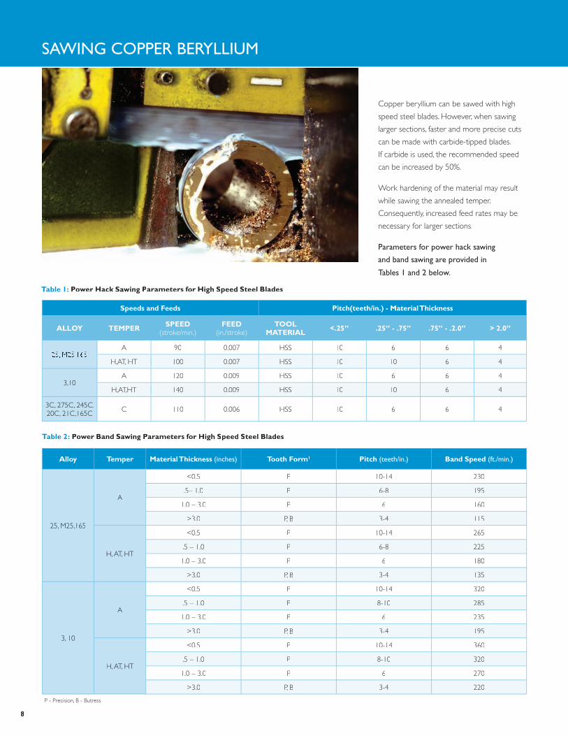
Copper beryllium can be sawed with high
speed steel blades. However, when sawing
larger sections, faster and more precise cuts
can be made with carbide-tipped blades.
If carbide is used, the recommended speed
can be increased by 50%.
Work hardening of the material may result
while sawing the annealed temper.
Consequently, increased feed rates may be
necessary for larger sections.
parameters for power hack sawing
and band sawing are provided in
Tables 1 and 2 below.
sAwING Copper beryllIuM
Table 2: power Band sawing parameters for high speed steel Blades
alloy Temper material Thickness (inches) Tooth form1 pitch (teeth/in.) Band speed (ft./min.)
25, M25,165
A
<0.5 P 10-14 230
.5– 1.0 P 6-8 195
1.0 – 3.0 P 6 160
>3.0 P, B 3-4 115
H, AT, HT
<0.5 P 10-14 265
.5 – 1.0 P 6-8 225
1.0 – 3.0 P 6 180
>3.0 P, B 3-4 135
3, 10
A
<0.5 P 10-14 320
.5 – 1.0 P 8-10 285
1.0 – 3.0 P 6 235
>3.0 P, B 3-4 195
H, AT, HT
<0.5 P 10-14 360
.5 – 1.0 P 8-10 320
1.0 – 3.0 P 6 270
>3.0 P, B 3-4 220
Table 1: power hack sawing parameters for high speed steel Blades
speeds and feeds pitch(teeth/in.) - material Thickness
alloy Temper speeD(stroke/min.)
feeD(in./stroke)
ToolmaTerIal <.25” .25” - .75” .75” - .2.0” > 2.0”
25, M25,165A 90 0.007 HSS 10 6 6 4
H,AT, HT 100H,AT, HT 100 0.007 HSS 10 10 6 4
3,10A 120 0.009 HSS 10 6 6 4
H,AT,HT 140H,AT,HT 140 0.009 HSS 10 10 6 4
3C, 275C, 245C,20C, 21C,165C C 110 0.006 HSS 10 6 6 4
8
1 P - Precision, B - Butress
TurNING Copper beryllIuM
Table 3: Turning parameters for carbide and high speed steel Tools
alloy Temper speed (ft./min.)1 feed (in./rev.) Tool material2
25, M25, 165
A 1500-1800 0.010-0.020 C-2
H 1200-1500 0.010-0.020 C-2
AT, HT 900-1200 0.010-0.020 C-2
3, 10 A, H, AT, HT 1500-1800 0.010-0.025 C-2
25, M25, 165
A 450-600 0.010-0.020 T-1
H 250-400 0.010-0.020 T-1
AT, HT 200-300 0.010-0.020 T-1
3, 10 A, H, AT, HT 600-700 0.010-0.025 M-2
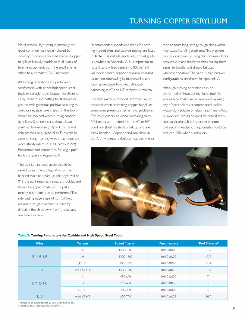
Metal removal by turning is probably the
most common method employed by
industry to produce finished shapes. Copper
beryllium is easily machined in all types of
turning equipment, from the small engine
lathes to automated CNC machines.
All turning operations are performed
satisfactorily with either high speed steel
tools or carbide tools. Copper beryllium is
easily sheared and cutting tools should be
ground with generous positive rake angles.
Zero or negative rake angles on the tools
should be avoided when turning copper
beryllium. Carbide inserts should have
positive clearance (e.g. , type C or P) and
chip grooves (e.g. , type M or T) except in
cases of rough turning which may require a
more sturdy insert (e. g. a CNMG insert).
Recommended geometries for single point
tools are given in Appendix A.
The side cutting edge angle should be
varied to suit the configuration of the
finished machined part, i.e. this angle will be
0˚ if the part requires a square shoulder, and
should be approximately 15˚ if just a
turning operation is to be performed. The
side cutting edge angle of 15˚ will help
prevent a rough-machined surface by
directing the chips away from the already
machined surface.
Recommended speeds and feeds for both
high speed steel and carbide tooling are listed
in Table 3. A carbide grade adjustment guide
is provided in Appendix A. It is important to
note that low feed rates (< 0.005 in./rev)
will work harden copper beryllium, changing will work harden copper beryllium, changing
its temper, decreasing its machinability and its temper, decreasing its machinability and
causing excessive tool wear, although causing excessive tool wear, although
hardening in AT and HT tempers is minimal.hardening in AT and HT tempers is minimal.
The high material removal rate that can be
achieved when machining copper beryllium
sometimes presents chip removal problems.
The chips produced when machining Alloy
M25 material or material in the AT or HT
condition (heat treated) break up and are
easily handled. Copper beryllium alloys in
the A or H tempers (before heat treatment)
tend to form long, stringy, tough chips which
may cause handling problems. This problem
can be overcome by using chip breakers. Chip
breakers curl and break the chips, making them
easier to handle, and should be used
whenever possible. The various chip breaker whenever possible. The various chip breaker
configurations are shown in Appendix A.
Although turning operations can be Although turning operations can be
performed without cutting fluids, tool life
and surface finish can be improved by using
any of the coolants recommended earlier.
Heavy-duty soluble emulsion and mineral/lard
oil mixtures should be used for critical form
tool applications. It is important to note
that recommended cutting speeds should be
reduced 25% when turning dry.
9
1 Reduce listed cutting speeds by 25% when turning dry.2 Classification of Tool Materials, Appendix A.
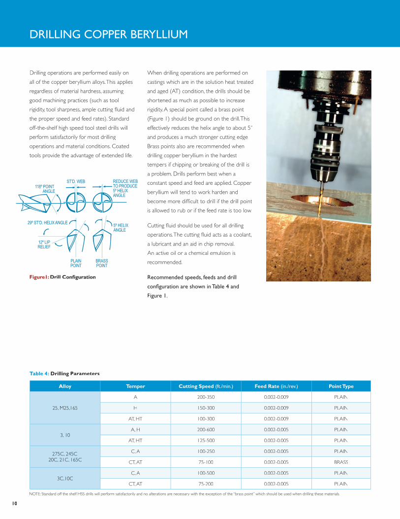
Drilling operations are performed easily on
all of the copper beryllium alloys. This applies
regardless of material hardness, assuming
good machining practices (such as tool
rigidity, tool sharpness, ample cutting fluid and
the proper speed and feed rates). Standard
off-the-shelf high speed tool steel drills will
perform satisfactorily for most drilling
operations and material conditions. Coated
tools provide the advantage of extended life.
When drilling operations are performed on
castings which are in the solution heat treated
and aged (AT) condition, the drills should be
shortened as much as possible to increase
rigidity. A special point called a brass point
(Figure 1) should be ground on the drill. This
effectively reduces the helix angle to about 5˚
and produces a much stronger cutting edge.
Brass points also are recommended when
drilling copper beryllium in the hardest
tempers if chipping or breaking of the drill is
a problem. Drills perform best when a
constant speed and feed are applied. Copper
beryllium will tend to work harden and
become more difficult to drill if the drill point
is allowed to rub or if the feed rate is too low.
Cutting fluid should be used for all drilling
operations. The cutting fluid acts as a coolant,
a lubricant and an aid in chip removal.
An active oil or a chemical emulsion is
recommended.
recommended speeds, feeds and drill
configuration are shown in Table 4 and
figure 1.
drIllING Copper beryllIuM
PLAINPOINT
BRASSPOINT
12º LIPRELIEF
5º HELIXANGLE
29º ST’D. HELIX ANGLE
118º POINT ANGLE
ST’D. WEB REDUCE WEBTO PRODUCE5º HELIXANGLE
figure1: Drill igure1: Drill igure1: configuration
10
Table 4: Drilling parameters
alloy Temper cutting speed (ft./min.) feed rate (in./rev.) point Type
25, M25,165
A 200-350 0.002-0.009 PLAIN
H 150-300 0.002-0.009 PLAIN
AT, HT 100-300 0.002-0.009 PLAIN
3, 10A, H 200-600 0.002-0.005 PLAIN
AT, HT 125-500 0.002-0.005 PLAIN
275C, 245C,20C, 21C, 165C
C, A 100-250 0.002-0.005 PLAIN
CT, AT 75-100 0.002-0.005 BRASS
3C,10CC, A 100-500 0.002-0.005 PLAIN
CT, AT 75-200 0.002-0.005 PLAIN
NOTE: Standard off the shelf HSS drills will perform satisfactorily and no alterations are necessary with the exception of the “brass point” which should be used when drilling these materials.
TAppING Copper beryllIuM
alloy Temper cutting speed (ft./min.)1
25, M25, 165
A 50-100
H 30-60
AT, HT 15-25
3, 10
A 20-150
H 10-60
AT, HT 10-100
275C, 245C,20C, 21C, 165C
C, A 20-50
CT, AT 5-10
3C, 10CC, A 10-75
CT, AT 10-50
1 Cutting speed is dependent largely on the rigidity of the tool; when tapping holes smaller than about 1/8” diameter, the low end of the cutting speed range should be used.
7º HOOK OR RAKEANGLE-MFG. ST’D.
SPIRAL PT.
CHAMFER TO SUIT
14º
figure 2: Tap igure 2: Tap igure 2: configuration
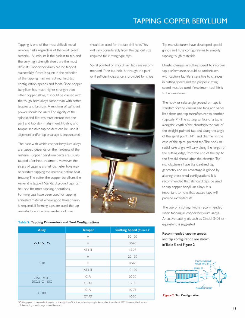
Tapping is one of the most difficult metal
removal tasks regardless of the work piece
material. Aluminum is the easiest to tap, and
the very high strength steels are the most
difficult. Copper beryllium can be tapped
successfully if care is taken in the selection
of the tapping machine, cutting fluid, tap
configuration, speeds and feeds. Since copper
beryllium has much higher strength than
other copper alloys, it should be classed with
the tough, hard alloys rather than with softer
brasses and bronzes. A machine of sufficient
power should be used. The rigidity of the
spindle and fixtures must ensure that the
part and tap stay in alignment. Floating and
torque sensitive tap holders can be used if
alignment and/or tap breakage is encountered.
The ease with which copper beryllium alloys
are tapped depends on the hardness of the
material. Copper beryllium parts are usually
tapped after heat treatment. However, the
stress of tapping a small diameter hole may
necessitate tapping the material before heat
treating. The softer the copper beryllium, the
easier it is tapped. Standard ground taps can
be used for most tapping operations.
Forming taps have been used for tapping
annealed material where good thread finish
is required. If forming taps are used, the tap
manufacturer’s recommended drill size
should be used for the tap drill hole. This
will vary considerably from the tap drill size
required for cutting type taps.
Spiral pointed or chip driver taps are recom-
mended if the tap hole is through the part
or if sufficient clearance is provided for chips.
Tap manufacturers have developed special
grinds and flute configurations to simplify
tapping tough materials.
Drastic changes in cutting speed, to improve
tap performance, should be undertaken
with caution. Tap life is sensitive to changes
in cutting speed and the proper cutting
speed must be used if maximum tool life is
to be maintained.
The hook or rake angle ground on taps is
standard for the various size taps, and varies
little from one tap manufacturer to another
(typically 7˚). The cutting surface of a tap is
along the length of the chamfer, in the case of
the straight pointed tap, and along the angle
of the spiral point (14˚) and chamfer, in the
case of the spiral pointed tap. The hook or
radial rake angle will vary along the length of
the cutting edge, from the end of the tap to
the first full thread after the chamfer. Tap
manufacturers have standardized tap
geometry and no advantage is gained by
altering these tried configurations. It is
recommended that standard taps be used
to tap copper beryllium alloys. It is
important to note that coated taps will
provide extended life.
The use of a cutting fluid is recommended
when tapping all copper beryllium alloys.
An active cutting oil, such as Cindol 3401 or
equivalent, is suggested.
recommended tapping speeds
and tap configuration are shown
in Table 5 and figure 2.
11
Table 5: Tapping parameters and Tool configurations
reAMING Copper beryllIuM
Table 6: reaming parameters
alloy Temper speed (ft./min.)1 feed (in./rev.)1
25, M25,165A, H 100-300 0.002-0.010
AT, HT 50-200 0.002-0.010
3, 10A, H 200-600 0.002-0.010
AT, HT 125-500 0.002-0.010
275C, 245C,20C, 21C, 165C
C, A 100-300 0.002-0.010
CT, AT 50-200 0.002-0.010
3C,10CC, A 200-600 0.002-0.010
CT, AT 125-500 0.002-0.010
Reaming is a hole sizing operation and should
only be included in the machining process
when holes of close dimension or good finish
are required. For best results, the reamer
should be held in a floating holder so that it is
free to follow the previously drilled or bored
hole. The hole diameter should be sized so
that the reamer has sufficient material into
which it can cut. An excess of 0.005 to 0.010
inch on a side is recommended.
The tendency is to use a very slow feed
when performing reaming operations. This is
generally done to produce a smooth surface
finish. It is important to note that, being a
work hardenable material, copper beryllium
will tend to harden at the surface that is in
contact with the cutting edges of the reamer.
This, in turn, makes it more difficult to cut. A
feed rate between 0.002 and 0.010 in./rev.
will minimize this hardening effect. Feed rates
below 0.002 in./rev. can be used when the
material is in the AT or HT temper since this
material is already in the hardened state and
the effect of cold working will be minimal.
To maximize the life of the reamer and the
quality of the reamed holes produced, a
cutting fluid should be used in copious
amounts. In addition to cooling the reamer,
an adequate supply of coolant will also
facilitate chip removal.
recommended speeds, feeds and reamer
configuration are shown in Table 6 and
figure 3.
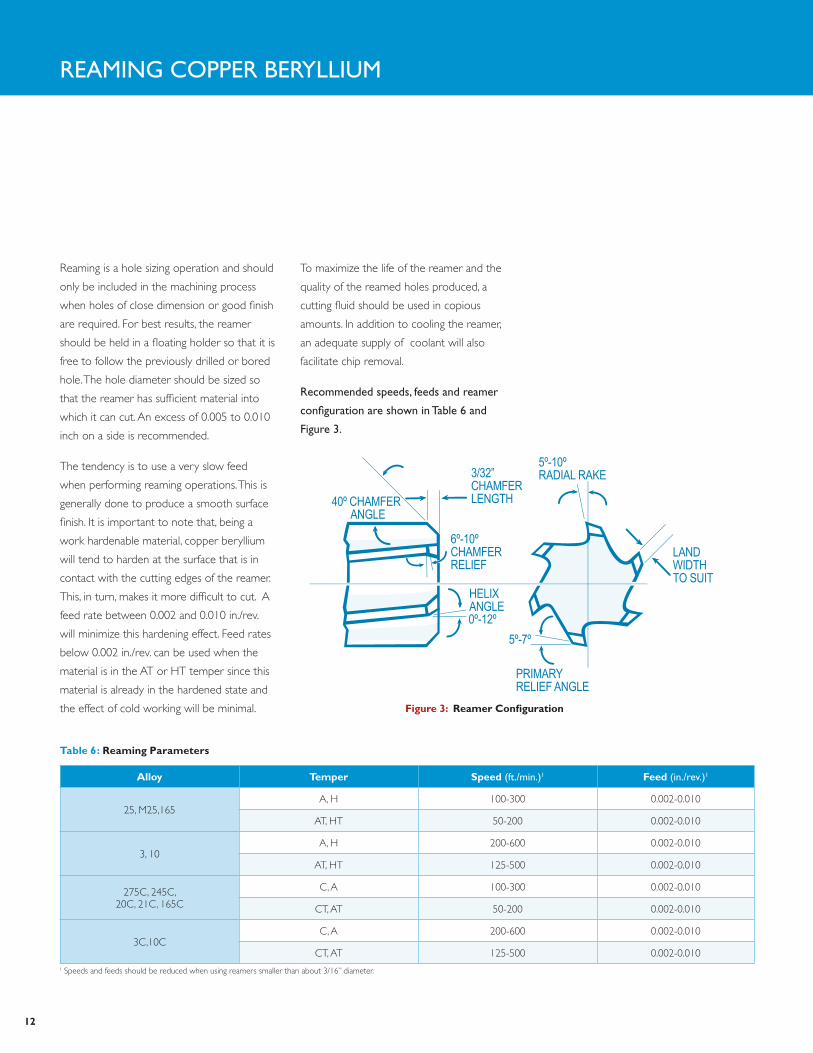
5º-10ºRADIAL RAKE
LANDWIDTHTO SUIT
PRIMARYRELIEF ANGLE
HELIXANGLE0º-12º
5º-7º
6º-10º CHAMFERRELIEF
3/32”CHAMFERLENGTH40º CHAMFER
ANGLE
figure 3: reamer configuration
12
1 Speeds and feeds should be reduced when using reamers smaller than about 3/16” diameter.
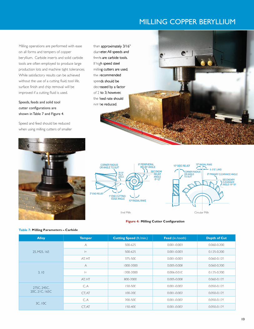
MIllING Copper beryllIuM
Table 7: milling parameters – carbide
alloy Temper cutting speed (ft./min.) feed (in./tooth) Depth of cut
25, M25, 165
AA 500-625500-625 0.001-0.003 0.060-0.200
H 500-625 0.001-0.003 0.125-0.200
AT, HT 375-500 0.001-0.003 0.060-0.125
3, 10
A 1000-2000 0.005-0.008 0.060-0.200
H 1200-2000 0.006-0.010 0.125-0.200
AT, HT 800-2000 0.005-0.008 0.060-0.125
275C, 245C,20C, 21C, 165C
C, A 150-500 0.001-0.002 0.050-0.125
CT, AT 100-200 0.001-0.002 0.050-0.125
3C, 10CC, A 200-500 0.001-0.002 0.050-0.125
CT, AT 150-400 0.001-0.002 0.050-0.125
CORNER RADIUSOR ANGLE TO SUIT
6º PERIPHERAL RELIEF ANGLE
1º END CUTTING EDGE ANGLE
10º RADIAL RAKE
26º-30ºHELIXANGLE
SECONDARYRELIEFANGLE8º-12º
3º END RELIEF
10º SIDE RELIEF
CORNER RADIUSOR ANGLETO SUIT
10º RADIAL RAKE
SECONDARYCLEARANCEANGLE-10º-15º
0-.015” LAND
6º PRIMARY CLEARANCE ANGLE
End Mills Circular Mills
figure 4: igure 4: igure 4: milling cutter configuration
Milling operations are performed with ease
on all forms and tempers of copper
beryllium. Carbide inserts and solid carbide
tools are often employed to produce large
production lots and machine tight tolerances.
While satisfactory results can be achieved
without the use of a cutting fluid, tool life,
surface finish and chip removal will be
improved if a cutting fluid is used.
speeds, feeds and solid tool
cutter configurations are
shown in Table 7 and figure 4.
Speed and feed should be reduced
when using milling cutters of smaller
than approximately 3/16”than approximately 3/16”
diameter.All speeds and diameter. All speeds and
feeds are carbide tools.feeds are carbide tools.
If high speed steel If high speed steel
milling cutters are used,milling cutters are used,
the recommended the recommended
speeds should be speeds should be
decreased by a factor decreased by a factor
of 2 to 3; however,of 2 to 3; however,
the feed rate should the feed rate should
not be reduced.not be reduced.
13
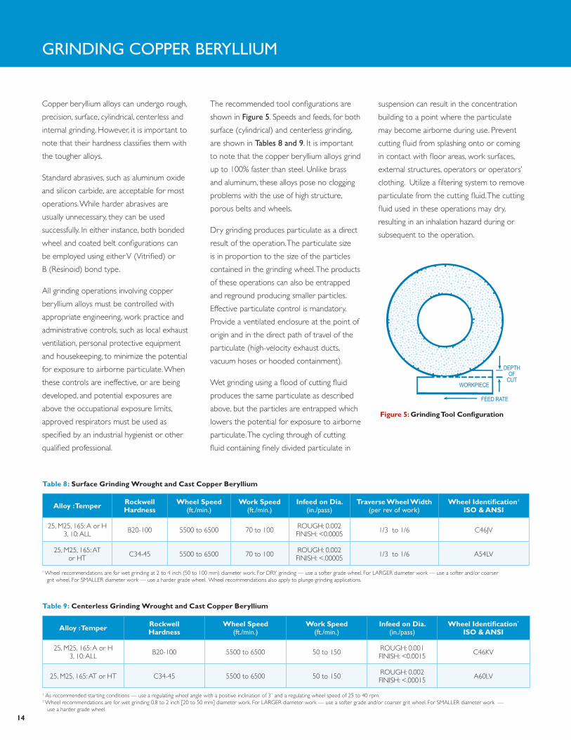
Copper beryllium alloys can undergo rough,
precision, surface, cylindrical, centerless and
internal grinding. However, it is important to
note that their hardness classifies them with
the tougher alloys.
Standard abrasives, such as aluminum oxide
and silicon carbide, are acceptable for most
operations. While harder abrasives are
usually unnecessary, they can be used
successfully. In either instance, both bonded
wheel and coated belt configurations can
be employed using either V (Vitrified) or
B (Resinoid) bond type.
All grinding operations involving copper
beryllium alloys must be controlled with
appropriate engineering, work practice and
administrative controls, such as local exhaust
ventilation, personal protective equipment
and housekeeping, to minimize the potential
for exposure to airborne particulate. When
these controls are ineffective, or are being
developed, and potential exposures are
above the occupational exposure limits,
approved respirators must be used as
specified by an industrial hygienist or other
qualified professional.
The recommended tool configurations are
shown in figure 5. Speeds and feeds, for both
surface (cylindrical) and centerless grinding,
are shown in Tables 8 and 9. It is important
to note that the copper beryllium alloys grind
up to 100% faster than steel. Unlike brass
and aluminum, these alloys pose no clogging
problems with the use of high structure,
porous belts and wheels.
Dry grinding produces particulate as a direct
result of the operation. The particulate size
is in proportion to the size of the particles
contained in the grinding wheel. The products
of these operations can also be entrapped
and reground producing smaller particles.
Effective particulate control is mandatory.
Provide a ventilated enclosure at the point of
origin and in the direct path of travel of the
particulate (high-velocity exhaust ducts,
vacuum hoses or hooded containment).
Wet grinding using a flood of cutting fluid
produces the same particulate as described
above, but the particles are entrapped which
lowers the potential for exposure to airborne
particulate. The cycling through of cutting
fluid containing finely divided particulate in
suspension can result in the concentration
building to a point where the particulate
may become airborne during use. Prevent
cutting fluid from splashing onto or coming
in contact with floor areas, work surfaces,
external structures, operators or operators’
clothing. Utilize a filtering system to remove
particulate from the cutting fluid. The cutting
fluid used in these operations may dry,
resulting in an inhalation hazard during or
subsequent to the operation.
Table 9: centerless Grinding Wrought and cast copper Beryllium
alloy : Temper rockwell hardness
Wheel speed(ft./min.)
Work speed (ft./min.)
Infeed on Dia. (in./pass)
Wheel Identification*
Iso & ansI
25, M25, 165: A or H3, 10: ALL B20-100 5500 to 6500 50 to 150 ROUGH: 0.001
FINISH: <0.0015 C46KV
25, M25, 165: AT or HT C34-45 5500 to 6500 50 to 150 ROUGH: 0.002FINISH: <.00015 A60LV
1 As recommended starting conditions — use a regulating wheel angle with a positive inclination of 3˚ and a regulating wheel speed of 25 to 40 rpm.2 Wheel recommendations are for wet grinding 0.8 to 2 inch [20 to 50 mm] diameter work. For LARGER diameter work — use a softer grade and/or coarser grit wheel. For SMALLER diameter work — use a harder grade wheel.
Table 8: surface Grinding Wrought and cast copper Beryllium
alloy : Temper rockwell hardness
Wheel speed(ft./min.)
Work speed (ft./min.)
Infeed on Dia. (in./pass)
Traverse Wheel Width (per rev of work)
Wheel Identification1
Iso & ansI
25, M25, 165: A or H3, 10: ALL B20-100 5500 to 6500 70 to 100 ROUGH: 0.002
FINISH: <0.0005 1/3 to 1/6 C46JV
25, M25, 165: AT or HT C34-45 5500 to 6500 70 to 100 ROUGH: 0.002
FINISH: <.00005 1/3 to 1/6 A54LV
1 Wheel recommendations are for wet grinding at 2 to 4 inch (50 to 100 mm) diameter work. For DRY grinding — use a softer grade wheel. For LARGER diameter work — use a softer and/or coarser grit wheel. For SMALLER diameter work — use a harder grade wheel. Wheel recommendations also apply to plunge grinding applications.
GrINdING Copper beryllIuM
DEPTHOF
CUTWORKPIECE
FEED RATE
figure 5: Grinding Tool configuration
14

Electrical Discharge Machining (EDM) is
commonly used to produce copper beryllium
molds and dies, to drill small, burr-free holes
and to make prototype quantities of contacts
for the aerospace and electronic markets.
EDM is not dependent on the strength or
hardness of the work piece and is used to
machine copper beryllium in its age hardened
state with no effect on the alloy’s strength and
no further heat treatment required.
Machining speeds are determined by the area
of the work piece, the work piece material
and the machining conditions. Since copper
beryllium exhibits high electrical conductivity,
machining rates are typically 20% lower than
that of tool steels. When EDM’ing copper
beryllium, it is suggested that the equipment
parameters be set at the machine manufacturer’s
recommendations for copper and then adjusted
accordingly to produce the desired results.
Compared to steel, copper beryllium must be
EDM’d with low amperage and high voltage to
produce acceptable results. The polarity of a
solid state power supply can be either electrode
positive or negative. Electrode negative polarity
produces the highest metal removal rates and
a rougher surface. Recently, it has become
more common to use electrode positive
polarity to increase the work-to-electrode
Table 10: example eDm parameters for copper Beryllium
1 The electrode was a 19mm dia rod.2 EDM 244TM is a trademark of Commonwealth Oil. The dielectric fluid was center flushed through the electrode.
Voltage 220 V
Current 50 A
Pulse on-time 32 µsec.
Duty factor 50%
Electrode gap 300 µm
Electrode polarity positive
Electrode material copper
Dielectric fluid EDM 244TM 2
Material removal rate (25 AT or HT)1 0.36 in.3/hr.
Material removal rate (3 AT or HT)1 0.22 in.3/hr.
Tool wear ratio (25 AT or HT) 0.33
Tool wear ratio (3 AT or HT) 0.87
eleCTrICAl dIsCHArGe MACHINING Copper beryllIuM
wear ratio, while providing a smoother
surface. A dielectric fluid is required in all EDM
operations. The dielectric acts as a spark
conductor, a coolant, and a flushing medium
that carries away swarf. For conventional
EDM, the most common Dielectric fluids used
are light petroleum-based oil for ram EDM
and deionized water for wire EDM.
The surface texture of EDM’d copper beryllium
resembles overlapping, small craters that
exhibit no directionality.The surface roughness
can range from 8 micro-inch Ra for finishing
operations, to 500 µ-in. Ra for roughing
operations. Recast and heat-affected layers
occur on the order of 0.0001 to 0.005 inch
and should be removed for fatigue-sensitive
applications. Shot peening provides a smoother
surface and improves fatigue life, but abrasive
and electrochemical methods are required to
remove the recast and underlying heat-affected
layer. For most applications, removal of these
layers is not necessary.
Travelling-wire (TW)-EDM utilizes the same
principles as conventional EDM. For TW-EDM,
brass and copper wire electrodes are most
frequently used, with other possibilities being
copper-tungsten, tungsten and molybdenum.
Usually, deionized water is the dielectric fluid
in TW-EDM. Wire diameters usually range
from 0.002 to 0.012 inch. Since the electrode
is only used once, electrode wear is not a
concern in most TW-EDM.
For TW-EDM, electrode (wire) negative
polarity is used. The machining rates of
copper beryllium are typically 20% lower than
that of tool steels. TW-EDM is used for both
roughing and finishing machining. Common
practice is to rough cut to about 0.004 in. of
finished dimensions, then follow with two or
three finishing passes. A finishing cut takes
about twice as long as a roughing cut, since
lower spark energies and a lower metal
removal rate must be used.
A TW-EDM surface exhibits a matte texture
with typically 30 to 50 µ-in. Ra roughness.
Since beryllium has been detected in the
atmosphere above the dielectric fluid during
EDM of copper beryllium, ventilation
equipment must be used. Care must be
exercised when cleaning and maintaining
EDM equipment that has been used to
machine copper beryllium. Care must be
exercised to assure that the particulate does
not dry or otherwise become airborne.
Do not clean equipment with air jets.
edM parameters taken from
an actual conventional ram
edM trial are shown in Table 10.
15
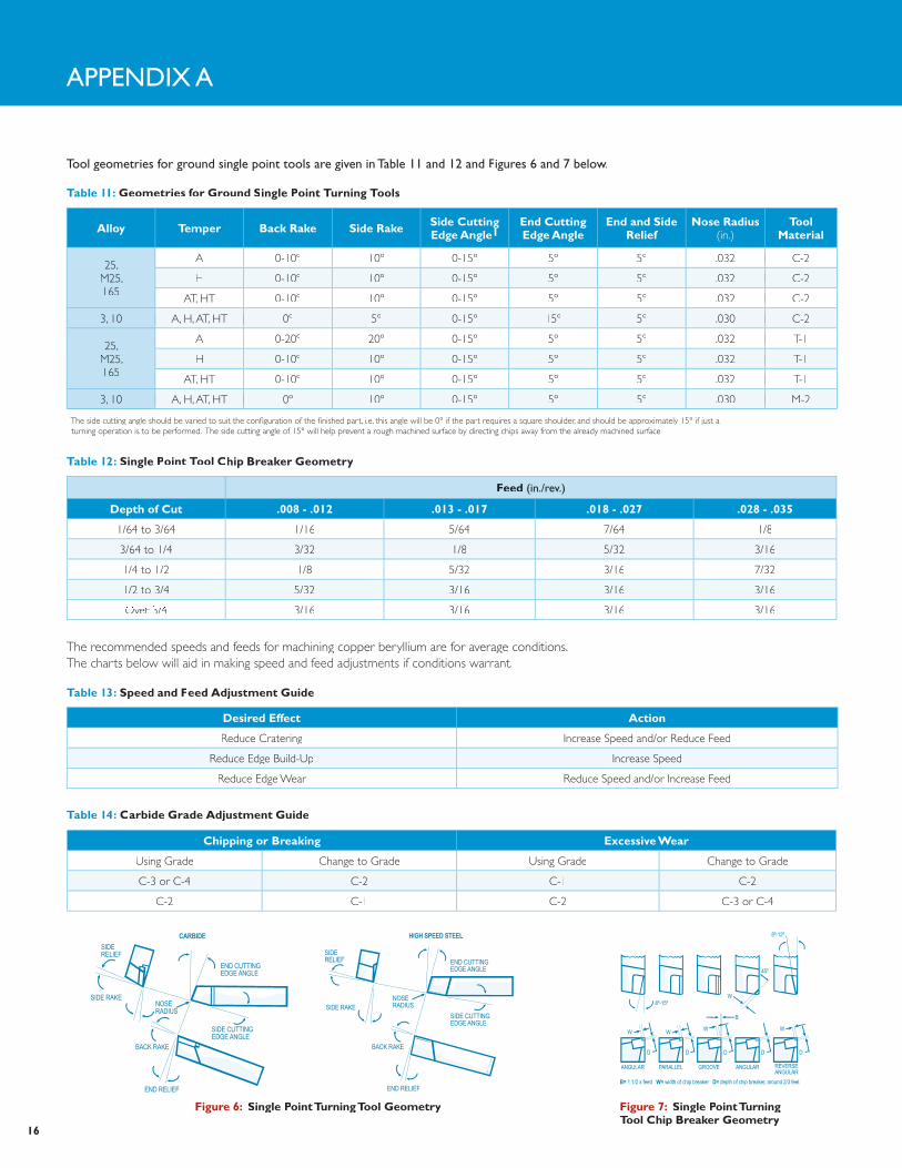
Tool geometries for ground single point tools are given in Table 11 and 12 and figures 6 and 7 below.
AppeNdIX A
Table 11: Geometries for Ground single point Turning Tools
alloy Temper Back rake side rake side cutting edge angle1
end cutting edge angle
end and side relief
nose radius(in.)
Tool material
25, M25, 165
A 0-10º 10º 0-15º 5º 5º .032 C-2.032 C-2
H 0-10º 10º 0-15º 5º 5º .032 C-2.032 C-2
AT, HT 0-10º 10º 0-15º 5º 5º .032 C-2.032 C-2
3, 10 A, H, AT, HT 0º3, 10 A, H,AT, HT 0º3, 10 A, H,AT, HT 0º3, 10 A, H,AT, HT 0º 5º 0-15º 15º 5º .030 C-2.030 C-2
25, M25, 165
A 0-20º 20º 0-15º 5º 5º .032 T-1.032 T-1
H 0-10º 10º 0-15º 5º 5º .032 T-1.032 T-1
AT, HT 0-10º 10º 0-15º 5º 5º .032 T-1.032 T-1
3, 10 A, H, AT, HT 0º3, 10 A, H,AT, HT 0º3, 10 A, H,AT, HT 0º3, 10 A, H,AT, HT 0º 10º 0-15º 5º 5º .030 M-2.030 M-2
1 The side cutting angle should be varied to suit the configuration of the finished part, i.e. this angle will be 0° if the part requires a square shoulder, and should be approximately 15° if just a turning operation is to be performed. The side cutting angle of 15° will help prevent a rough machined surface by directing chips away from the already machined surface.
Appendix A
Table 12: single point Tool chip Breaker Geometry
feed (in./rev.)
Depth of cut .008 - .012 .013 - .017 .018 - .027 .028 - .035
1/64 to 3/64 1/16 5/64 7/64 1/8
3/64 to 1/4 3/32 1/8 5/32 3/16
1/4 to 1/2 1/8 5/32 3/16 7/32
1/2 to 3/4 5/32 3/16 3/16 3/16
Over 3/4Appendix A
Over 3/4Appendix A
3/16 3/16 3/16 3/16
Table 13: speed and feed adjustment Guide
Desired effect action
Reduce Cratering Increase Speed and/or Reduce Feed
Reduce Edge Build-Up Increase Speed
Reduce Edge Wear Reduce Speed and/or Increase Feed
Table 14: carbide Grade adjustment Guide
chipping or Breaking excessive Wear
Using Grade Change to Grade Using Grade Change to Grade
C-3 or C-4 C-2 C-1 C-2
C-2 C-1 C-2 C-3 or C-4
END CUTTINGEDGE ANGLE
SIDE CUTTINGEDGE ANGLE
NOSERADIUS
SIDERELIEF
SIDE RAKE
BACK RAKE
END RELIEF
HIGH SPEED STEELSIDERELIEF
SIDE RAKENOSERADIUS
BACK RAKE
END RELIEF
SIDE CUTTINGEDGE ANGLE
END CUTTINGEDGE ANGLE
CARBIDE
figure 6: single point Turning Tool Geometry
8º-15º
8º-12º
45º
W
W
D DDDD
WWW
B
ANGULAR PARALLEL GROOVE ANGULAR REVERSEANGULAR
B= 1 1/2 x feed W= width of chip breaker D= depth of chip breaker, around 2/3 feet
figure 7: single point Turning Tool chip Breaker Geometry
16
The recommended speeds and feeds for machining copper beryllium are for average conditions. The charts below will aid in making speed and feed adjustments if conditions warrant.The charts below will aid in making speed and feed adjustments if conditions warrant.
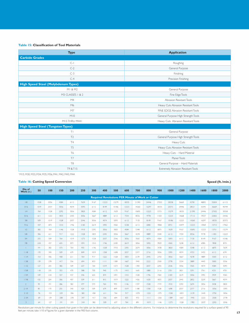
Table 15: classification of Tool materials
Type application
carbide Grades
C-1 Roughing
C-2 General Purpose
C-3 Finishing
C-4 Precision Finishing
high speed steel (molybdenum Types)
M1 & M2 General Purpose
M3 CLASSES 1 & 2 Fine Edge Tools
M4 Abrasion Resistant Tools
M6 Heavy Cuts Abrasion Resistant Tools
M7 FINE EDGE Abrasion Resistant Tools
M10 General Purpose High Strength Tools
M15 THRU M441 Heavy Cuts Abrasion Resistant Tools
high speed steel (Tungsten Types)
T1 General Purpose
T2 General Purpose High Strength Tools
T4 Heavy Cuts
T5 Heavy Cuts Abrasion Resistant Tools
T6 Heavy Cuts – Hard Material
T7 Planer Tools
T8 General Purpose – Hard Materials
T9 & T15 Extremely Abrasion Resistant Tools
Revolutions per minute for other cutting speeds than given in the table can be determined by adjusting values in the different columns. For instance, to determine the revolutions required for a surface speed of 90 feet per minute, take 1/10 of figures for a given diameter in the 900 foot column.
Dia. of Work (in.) 50 100 150 200 250 300 400 500 600 700 800 900 1000 1200 1400 1600 1800 2000
required revolutions per minute of Work or cutter
1/8 1528 3056 4584 6112 7639 9167 12223 15279 18335 21390 24446 27502 30558 36669 42781 48892 55004 61115
3/16 1019 2037 3056 4074 5093 6112 8149 10186 12223 14260 16297 18335 20372 24446 28521 32595 36669 40744
1/4 764 1528 2292 3056 3820 4584 6112 7639 9167 10695 12223 13751 15279 18335 21390 24446 27502 30558
5/16 611 1222 1833 2445 3056 3667 4889 6112 7334 8556 9778 11001 12223 14668 17112 19557 22002 24446
3/8 509 1019 1528 2037 2546 3056 4074 5093 6112 7130 8149 9167 10186 12223 14260 16297 18335 20372
7/16 437 873 1310 1746 2183 2619 3492 4365 5238 6112 6985 7858 8731 10477 12223 13969 15715 17462
1/2 382 764 1146 1528 1910 2292 3056 3820 4584 5348 6112 6875 7639 9167 10695 12223 13751 15279
5/8 306 611 917 1222 1528 1833 2445 3056 3667 4278 4889 5500 6112 7334 8556 9778 11001 12223
3/4 255 509 764 1019 1273 1528 2037 2546 3056 3565 4074 4584 5093 6112 7130 8149 9167 10186
7/8 218 437 655 873 1091 1310 1746 2183 2619 3056 3492 3929 4365 5238 6112 6985 7858 8731
1 191 382 573 764 955 1146 1528 1910 2292 2674 3056 3438 3820 4584 5348 6112 6875 7639
1 1/8 170 340 509 679 849 1019 1358 1698 2037 2377 2716 3056 3395 4074 4753 5432 6112 6791
1 1/4 153 306 458 611 764 917 1222 1528 1833 2139 2445 2750 3056 3667 4278 4889 5500 6112
1 3/8 139 278 417 556 694 833 1111 1389 1667 1945 2222 2500 2778 3334 3889 4445 5000 5556
1 1/2 127 255 382 509 637 764 1019 1273 1528 1783 2037 2292 2546 3056 3565 4074 4584 5093
1 5/8 118 235 353 470 588 705 940 1175 1410 1645 1880 2116 2351 2821 3291 3761 4231 4701
1 3/4 109 218 327 437 546 655 873 1091 1310 1528 1746 1964 2183 2619 3056 3492 3929 4365
1 7/8 102 204 306 407 509 611 815 1019 1222 1426 1630 1833 2037 2445 2852 3259 3667 4074
2 95 191 286 382 477 573 764 955 1146 1337 1528 1719 1910 2292 2674 3056 3438 3820
2 1/4 85 170 255 340 424 509 679 849 1019 1188 1358 1528 1698 2037 2377 2716 3056 3395
2 1/2 76 153 229 306 382 458 611 764 917 1070 1222 1375 1528 1833 2139 2445 2750 3056
2 3/4 69 139 208 278 347 417 556 694 833 972 1111 1250 1389 1667 1945 2222 2500 2778
3 64 127 191 255 318 382 509 637 764 891 1019 1146 1273 1528 1783 2037 2292 2546
Table 16: cutting speed conversion speed (ft./min.)
17
1 M15, M30, M33, M34, M35, M36, M41, M42, M43, M44
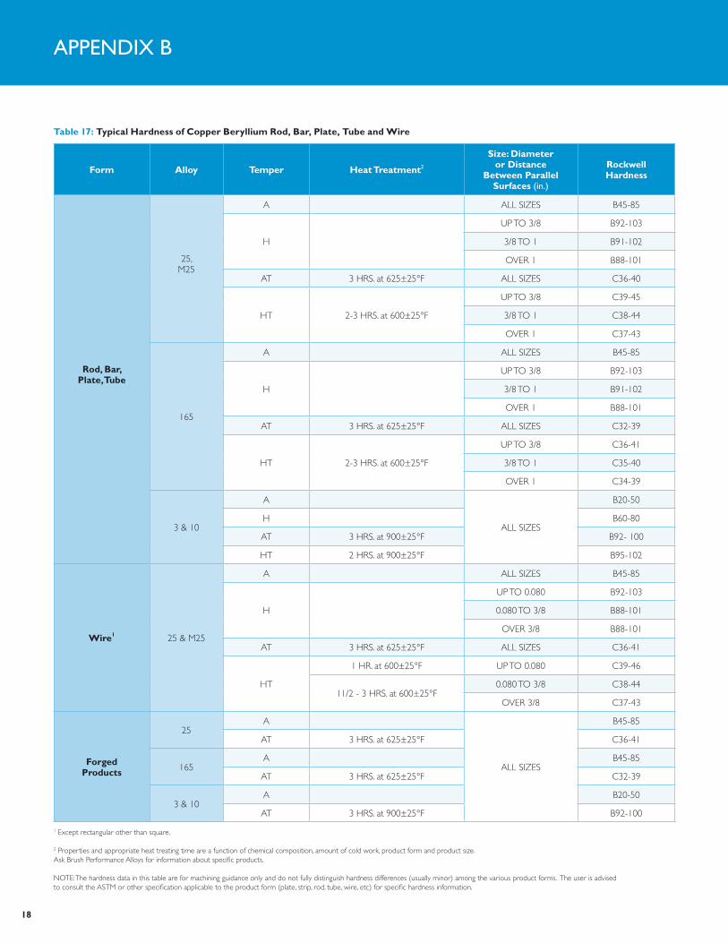
Table 17: Typical hardness of copper Beryllium rod, Bar, plate, Tube and Wire
form alloy Temper heat Treatment2
size: Diameter or Distance
Between parallel surfaces (in.)
rockwellhardness
rod, Bar,plate, Tube
25,M25
A ALL SIZES B45-85
H
UP TO 3/8 B92-103
3/8 TO 1 B91-102
OVER 1 B88-101
AT 3 HRS. at 625±25°F ALL SIZES C36-40
HT 2-3 HRS. at 600±25°F
UP TO 3/8 C39-45
3/8 TO 1 C38-44
OVER 1 C37-43
165
A ALL SIZES B45-85
H
UP TO 3/8 B92-103
3/8 TO 1 B91-102
OVER 1 B88-101
AT 3 HRS. at 625±25°F ALL SIZES C32-39
HT 2-3 HRS. at 600±25°F
UP TO 3/8 C36-41
3/8 TO 1 C35-40
OVER 1 C34-39
3 & 10
A
ALL SIZES
B20-50
H B60-80
AT 3 HRS. at 900±25°F B92- 100
HT 2 HRS. at 900±25°F B95-102
Wire1 25 & M25
A ALL SIZES B45-85
H
UP TO 0.080 B92-103
0.080 TO 3/8 B88-101
OVER 3/8 B88-101
AT 3 HRS. at 625±25°F ALL SIZES C36-41
HT
1 HR. at 600±25°F UP TO 0.080 C39-46
11/2 - 3 HRS. at 600±25°F0.080 TO 3/8 C38-44
OVER 3/8 C37-43
forged products
25A
ALL SIZES
B45-85
AT 3 HRS. at 625±25°F C36-41
165A B45-85
AT 3 HRS. at 625±25°F C32-39
3 & 10A B20-50
AT 3 HRS. at 900±25°F B92-100
1 Except rectangular other than square.
2 Properties and appropriate heat treating time are a function of chemical composition, amount of cold work, product form and product size. Ask Brush Performance Alloys for information about specific products.
NOTE: The hardness data in this table are for machining guidance only and do not fully distinguish hardness differences (usually minor) among the various product forms. The user is advised to consult the ASTM or other specification applicable to the product form (plate, strip, rod, tube, wire, etc) for specific hardness information.
AppeNdIX b
18
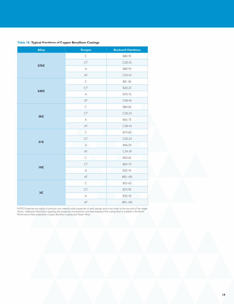
Table 18: Typical hardness of copper Beryllium castings
alloy Temper rockwell hardness
275c
C B80-90
CT C20-25
A B80-95
AT C43-47
245c
C B81-86
CT B20-25
A B70-76
AT C40-45
20c
C B80-85
CT C20-24
A B65-75
AT C38-43
21c
C B74-82B74-82
CT C20-24
A B46-54
AT C34-39
10c
C B50-60
CT B65-75
A B35-45B35-45
AT B92-100
3c
C B55-65B55-65
CT B75-90
A B35-45
AT B92-100
NOTE: Properties are typical of precision cast material, while properties of sand castings tend to be closer to the low end of the ranges NOTE: Properties are typical of precision cast material, while properties of sand castings tend to be closer to the low end of the ranges NOTE: Properties are typical of precision cast material, while properties of sand castings tend to be closer to the low end of the ranges NOTE: Properties are typical of precision cast material, while properties of sand castings tend to be closer to the low end of the ranges NOTE: Properties are typical of precision cast material, while properties of sand castings tend to be closer to the low end of the ranges NOTE: Properties are typical of precision cast material, while properties of sand castings tend to be closer to the low end of the ranges shown. Additional information regarding the properties, characteristics and heat treating of the casting alloys is available in the Brush shown. Additional information regarding the properties, characteristics and heat treating of the casting alloys is available in the Brush shown. Additional information regarding the properties, characteristics and heat treating of the casting alloys is available in the Brush shown. Additional information regarding the properties, characteristics and heat treating of the casting alloys is available in the Brush shown. Additional information regarding the properties, characteristics and heat treating of the casting alloys is available in the Brush shown. Additional information regarding the properties, characteristics and heat treating of the casting alloys is available in the Brush Performance Alloys publication, Copper Beryllium Casting and Master Alloys.Performance Alloys publication, Copper Beryllium Casting and Master Alloys.Performance Alloys publication, Copper Beryllium Casting and Master Alloys.Performance Alloys publication, Copper Beryllium Casting and Master Alloys.
1919
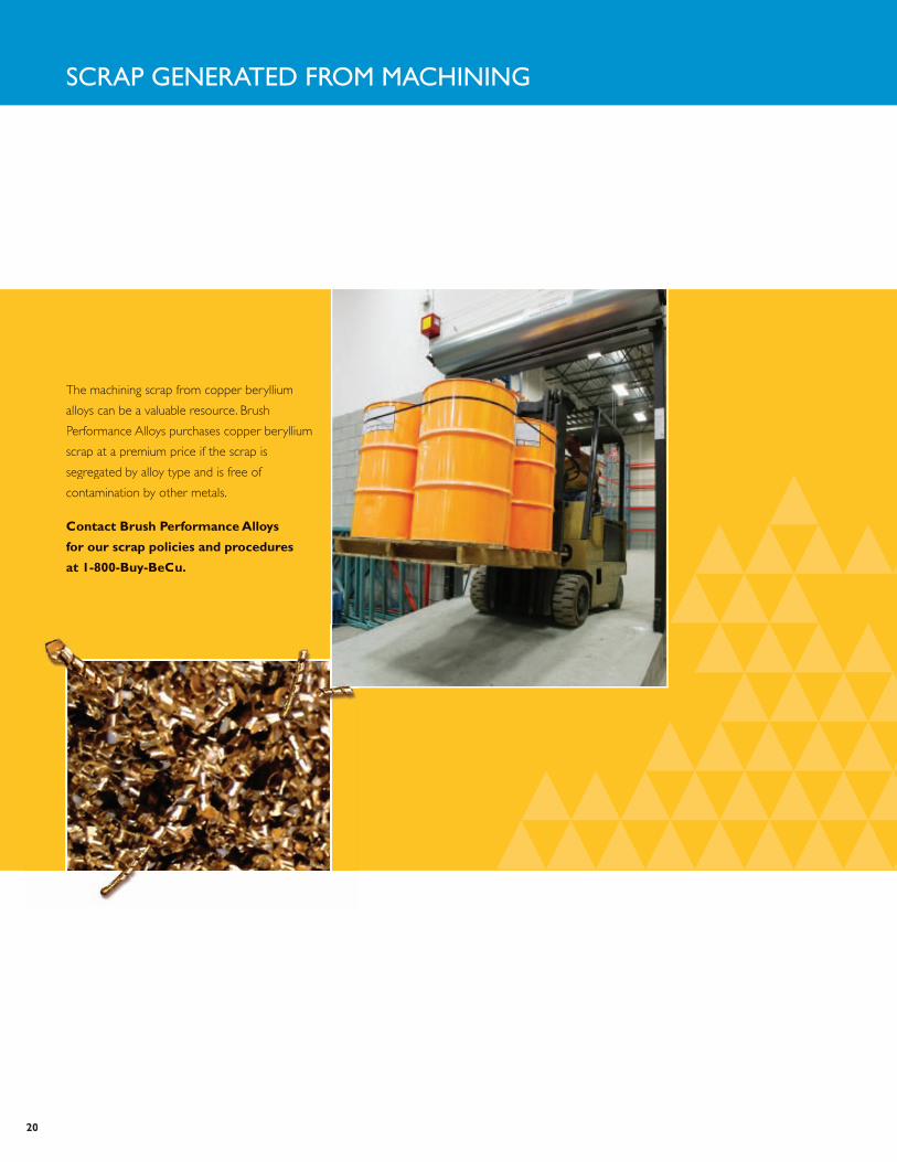
sCrAp GeNerATed froM MACHINING
The machining scrap from copper beryllium
alloys can be a valuable resource. Brush
Performance Alloys purchases copper beryllium
scrap at a premium price if the scrap is
segregated by alloy type and is free of
contamination by other metals.
contact Brush performance alloys
for our scrap policies and procedures
at 1-800-Buy-Becu.
20
Brush Peformance Alloysrush Peformance Alloysrush Peformance Alloysrush Peformance Alloysrush Peformance Alloysrush Peformance Alloysrush Peformance Alloysrush Peformance Alloysrush Peformance Alloysrush Peformance Alloysrush Peformance Alloysrush Peformance Alloysrush Peformance Alloysrush Peformance Alloys
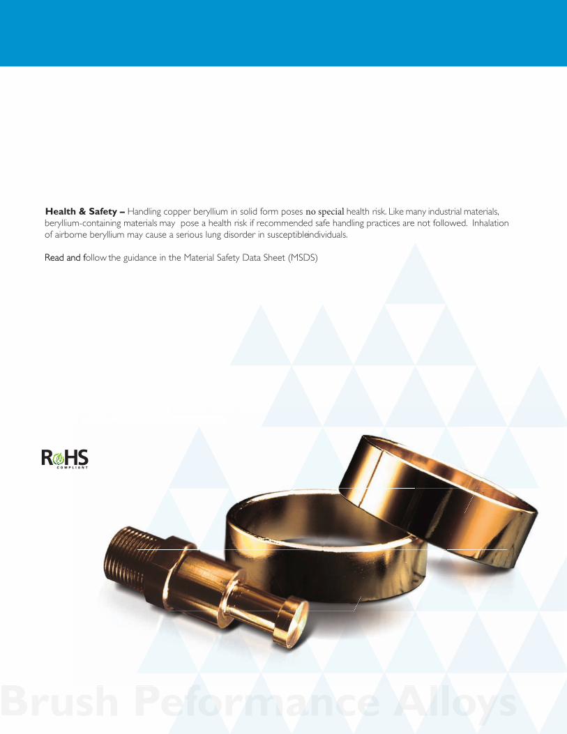
Handling copper beryllium in solid for Handling copper beraf Handling copper beryllium in solid form poses no special afhealth risk. Like many industrial materials, beryllium-containing materhealth risk. Like many industrial materials, ber ials may isk. Like many industrial materials, beryllium-containing materials may
wed.pose a health risk if recommended safe handling practices are not fpose a health risk if recommended safe handling pr ollowed.Inhalation of airborne beryllium may cause a serInhalation of airborne beryllium may cause a ser le individuals.The Occupational Safety and Health Administrindividuals.The Occupational Safety and Health Administrindividuals.The Occupational Safety and Health has set mandatory limits on occupational respiratory exposures. Read and follohas set mandatory limits on occupational respirator ollow the guidance in the Material Safety Data Sheet (MSDS) befthis material. For additional information on safe handling prthis material. For additional information on safe handling prial. For additional information on safe handling practices or technical
yllium, contact erfT
health & safety – Handling copper beryllium in solid form poses no special health risk. Like many industrial materials, beryllium-containing materials may pose a health risk if recommended safe handling practices are not followed. Inhalation of airborne beryllium may cause a serious lung disorder in susceptible individuals.
Read and f Read and follow the guidance in the Material Safety Data Sheet (MSDS)


