Chapter 23 Machining Processes Used to Produce Round Shapes: Turning and Hole Making QUALITATIVE PROBLEMS 23.15 Explain the reasoning behind the various design guidelines for turning. By the student. The design guidelines, given in Section 23.3.6 on p. 697, are mostly self- explanatory, such as the need to design parts so that they can be easily fixtured. However, some examples of some reasoning are as follows: • Sharp corners, tapers, steps, and major dimensional variations in the part should be avoided. It’s easiest for a lathe to be set up to perform straight turning, thus unnecessary dimensional variations make the lathe operation much more difficult. The difficulty with sharp corners, especially internal corners, is that the minimum corner radius is that of the nose radius of the cutting tool (see Figs. 21.15 on p. 627, 21.23 on p. 637, and 23.4c on p. 677). Also, small nose radii lead to increased likelihood of tool chipping or breakage. • Blanks to be machined should be as close to the final dimensions as possible; this is, of course, a valuable general concept. It is important in turning because tool life is limited and the number of roughing cuts before a finishing cut is taken should be minimized. 23.16 You will note that we have used both the terms “tool strength” and “tool-material strength.” Do you think there is a difference between them? Explain. By the student. There is a difference between tool-material strength and tool strength. Tool material strength is a property of the material (see Table 22.1 on p. 649); thus, for example, the compressive strength of carbides is higher than that for high-speed steels. The tool 235
Transcript
Chapter 23
Machining Processes Used to ProduceRound Shapes: Turning and HoleMaking
QUALITATIVE PROBLEMS
23.15 Explain the reasoning behind the various design guidelines for turning.
By the student. The design guidelines, given in Section 23.3.6 on p. 697, are mostly self-explanatory, such as the need to design parts so that they can be easily fixtured. However,some examples of some reasoning are as follows:
• Sharp corners, tapers, steps, and major dimensional variations in the part should beavoided. It’s easiest for a lathe to be set up to perform straight turning, thus unnecessarydimensional variations make the lathe operation much more difficult. The difficulty withsharp corners, especially internal corners, is that the minimum corner radius is that ofthe nose radius of the cutting tool (see Figs. 21.15 on p. 627, 21.23 on p. 637, and23.4c on p. 677). Also, small nose radii lead to increased likelihood of tool chipping orbreakage.
• Blanks to be machined should be as close to the final dimensions as possible; this is, ofcourse, a valuable general concept. It is important in turning because tool life is limitedand the number of roughing cuts before a finishing cut is taken should be minimized.
23.16 You will note that we have used both the terms “tool strength” and “tool-materialstrength.” Do you think there is a difference between them? Explain.
By the student. There is a difference between tool-material strength and tool strength. Toolmaterial strength is a property of the material (see Table 22.1 on p. 649); thus, for example,the compressive strength of carbides is higher than that for high-speed steels. The tool
235
Machining Processes Used to Produce Round Shapes 236
strength, on the other hand, refers to the ability of a particular cutting tool to resist fractureor failure. This depends not only on the tool material itself but also on the tool geometry, asshown in Figs. 22.4 and 22.5 on p. 655.
23.17 Explain why the sequence of drilling, boring, and reaming produces a hole thatis more accurate than just drilling and reaming it.
The difficulty is largely due to the fact that drilling, because of its inherent flexibility, does notnecessarily produce a hole that is accurate in its coordinate, whereas boring is an operationthat is better controlled.
23.18 Explain why machining operations may be necessary even on net-shape or near-net-shape parts made by precision casting, forming, or powder-metallurgy prod-ucts.
By the student. Many applications require better dimensional tolerances or surface finish thanthose produced by casting, forging, or powder metallurgy. Machining operations can removeunevenness from parts, such as those caused by defects or through uneven deformation andwarping upon cooling. Many processes, by their nature, will not impart a sufficiently smoothsurface finish to the workpiece, and it is often necessary to machine (or grind, polish, etc.)them for improved dimensional accuracy. Other parts require surface features that cannot beobtained through other manufacturing methods.
23.19 What are the consequences of drilling with a drill bit that has not been properlysharpened?
By the student. The consequences are similar to those shown in Fig. 21.22 on p. 636. Notethat drilling is similar to the cutting operation shown, except that a circular chip is removed.Thus, a drill bit that is not properly sharpened has a large nose radius, and this has theconsequences of causing the effective rake angle to increase (so that the force and energyrequired are increased, as is temperature), as well as increase the likelihood of surface smearingand burnishing, instead of removing material.
23.20 A badly oxidized and uneven round bar is being turned on a lathe. Would yourecommend a small or a large depth-of-cut? Explain your reasons.
Because oxides are generally hard and abrasive (see p. 1037), consequently, light cuts willcause the tool to wear rapidly. Thus it is highly desirable to cut right through the oxidelayer on the first pass. Note that an uneven round bar will cause significant variations in thedepth of cut being taken; thus, depending on the degree of eccentricity, it may not always bepossible to do so since this can be self-excited vibration and lead to chatter.
23.21 Describe the problems, if any, that may be encountered in clamping a workpiecemade of a soft metal in a three-jaw chuck.
A common problem in clamping any workpiece into a chuck is that the jaws will bite into theworkpiece (see, for example, Fig. 23.3 on p. 677), possibly leaving an impression that may beunsightly or functionally unacceptable. Shim stock, made of a softer material, can be usedbetween the jaws and the workpiece to minimize damage to the workpiece surface. Parts mayalso be designed for convenient clamping into chucks, or provided with flanges or extensionswhich can be gripped by the chuck, which can later be removed.
Machining Processes Used to Produce Round Shapes 237
23.22 Does the force or torque in drilling change as the hole depth increases? Explain.
The force and torque may increase as the hole depth increases, but not by a significantamount. The factors which would increase the force and torque are contact area between thetool and cylindrical surface of the hole and difficulties in removing chips from the bottomof deep holes and possible clogging. Unless the hole depth is very deep, these are usuallyconsidered unimportant and the force and torque can be taken as constant.
23.23 Explain the similarities and differences in the design guidelines for turning andfor boring.
By the student. Turning and boring are quite similar operations in terms of dimensionaltolerances and surface finish. In both cases, secure clamping is necessary, which is the reasonthe clamped lengths are similar. Interrupted surfaces in both cases can lead to vibration andchatter. The differences in the two operations are that, in boring, the workpiece size is notcritical. Workpieces that are suitable for boring can naturally be held in various fixtures, andvertical boring machines can accommodate very large parts (see, for example, Fig. 23.18 onp. 704). On the other hand, in typical turning operations very large parts can be difficult tomount.
23.24 What are the advantages and applications of having a hollow spindle in the head-stock of a lathe?
The main advantage is the ability to feed stock through the headstock of the lathe (Fig. 23.2).This is particularly important in automatic bar machines (see p. 691).
23.25 Explain how you would go about producing a taper on a round workpiece on alathe.
Tapers can be produced by mounting the round workpiece out of line with the tailstock. Inaddition, tapers can be machined using a template on a tracer lathe. In modern practice,however, tapers and various other shapes are machined automatically and economically usingnumerical-control (CNC) lathes. Note in Figs. 23.11 and 23.12 on pp. 694 and 695, forexample, the complex shapes that can be machined on such lathes.
23.26 Assume that you are asked to perform a boring operation on a large-diameterhollow workpiece. Would you use a horizontal or a vertical boring mill? Explain.
By the student. It is apparent that, because of size and weight limitations, a horizontal setupis desirable. See, for example, Fig. 23.18 mon p. 704.
23.27 Explain the reasons for the major trend in producing threads by thread rollingversus thread cutting. What would be the differences (if any) in the types ofthreads produced and their performance characteristics?
By the student. Thread rolling is described on pp. 362-364. The main advantages of threadrolling over thread cutting are the speeds involved (thread rolling is a very high productionrate process) and the fact that the threads will undergo extensive cold working (plastic de-formation; see Fig. 13.17c), leading to stronger work-hardened threads. Cutting is still usedfor making threads(see Section 23.3.8 on p. 700) because it is a very versatile operation andmuch more economical for low production runs (since expensive dies are not required). Note
Machining Processes Used to Produce Round Shapes 238
that internal threads also can be rolled, but this is not nearly as common as machining thethreads and can be a difficult operation.
23.28 In some materials the hole drilled can be smaller than the diameter of the drill.Explain this phenomenon and identify the relevant material properties that couldinfluence it.
It’s not difficult to visualize why this situation can occur. Examining the geometry of drillsin Fig. 23.19 on p. 705, one can see that as the drill progressively moves into a hole it isproducing, it is loading the workpiece material radially. When the drill is removed, elasticrecovery can lead to a smaller hole. Also note that residual stresses are relieved by removingmaterial in drilling, and when the drill is removed, elastic recovery can lead to a smaller holethan the drill diameter.
23.29 Describe your observations concerning the contents of Tables 23.2 and 23.4 andexplain why those particular recommendations are made.
By the student. Some observations are listed below:
• Referring to Table 23.2 on p. 678, note that the side rake angle is high for aluminumbut low for titanium. This can be explained by the benefits of maintaining highercompression on the shear plane for titanium (to obtain higher ductility), a situation notneeded for aluminum.
• Note from Table 23.4 on p. 682 that the cutting speeds for steels are much lower thanthose for copper alloys. This can be explained by power requirements associated withmachining steels.
• Note that the tools used in Table 23.4 vary by workpiece material. For example, nodiamond is listed for steel, explainable by the solubility of carbon in steel at elevatedtemperatures.
23.30 We have seen that cutting speed, feed, and depth-of-cut are the main parametersin a turning operation. In relative terms, at what values should these parametersbe set for a (a) roughing operation and (b) finishing operation?
(a) For a finishing operation, with good surface finish, they should be set at high speed,low feed, and low depth of cut. (b) For a roughing operation, where surface finish is not asimportant, they should be set at low speed and high feed and depth of cut. This can be seenfrom Eq. (21.24) and Fig. 21.23 on p. 637: where surface finish is critical, feed and depth ofcut should be low. Speed does not appear in this equation; the main effect of speed is togenerate chatter at higher speeds. This, when surface finish is not critical, speed can be sethigh. When surface finish is critical, it is important to avoid chatter. This is discussed ingreater detail in Section 25.4 on p. 775.
23.31 Explain the economic justification for purchasing a turret lathe instead of a con-ventional lathe.
As we have seen, turret lathes (see p. 692) have multiple tools and can perform a variety ofoperations such as turning, threading, drilling, facing, and cut off. Thus, the amount of timerequired for setting up the tools is greatly reduced as compared to common lathe operations.
Machining Processes Used to Produce Round Shapes 239
Because manufacturing time is an important element in the overall cost of production (seeSection 40.9), turret lathes can be justified economically.
23.32 The footnote to Table 23.11 states that (in drilling) as the hole diameter increases,speeds and feeds should be reduced. Explain why.
As hole depth increases, elastic recovery in the workpiece causes normal stresses on the surfaceof the drill, thus the stresses experienced by the drill are higher than they are in shallow holes.These stresses, in turn, cause the torque on the drill to increase and may even lead to itsfailure. Reduction in feeds and speeds can compensate for these increases.
23.33 In modern manufacturing with computer-controlled machine tools, which typesof metal chips would be undesirable and why?
Referring to Fig. 21.5 on p. 614, we note the following: Continuous chips are not desirablebecause (a) the machines mostly untended and operate at high speeds, thus chip generation isat a high rate (see also chip collection systems, p. 700) and (b) continuous chips would entangleon spindles and machine components, and thus severely interfere with the cutting operation.Conversely and for that reason, discontinuous chips or segmented chips would be desirable,and indeed are typically produced using chipbreaker features on tools, Note, however, thatsuch chips can lead to vibration and chatter, depending also on the characteristics of themachine tool (see Section 25.4 on p. 775).
23.34 List and explain the factors that contribute to poor surface finish in the processesdescribed in this chapter.
By the student. One factor is explained by Eq. (21.24) on p. 637, which gives the roughness ina process such as turning. Clearly, as the feed increases or as the tool nose radius decreases,the roughness will increase. Other factors that affect surface finish are built-up edge (see, forexample, Figs. 21.5 and 21.6 on pp. 614-615), dull tools or tool-edge chipping (see Fig. 21.18on p. 632), or chatter (Section 25.4 on p. 775).
23.35 The operational severity for reaming is much less than that for tapping, eventhough they are both internal material-removal processes which can be difficult.Why?
Tapping (p. 716) produces a significant amount of chips and their removal through the holebeing tapped can be difficult as they can get clogged (and can cause tap fracture), thuscontributing to the severity of the tapping operation. Control of processing parameters anduse of effective cutting fluids are thus important. Chipless tapping, on the other hand, doesnot present such difficulties.
23.36 Review Fig. 23.6 and comment on the factors involved in determining the heightof the zones (cutting speed) for various tool materials.
The main reasons for a range of acceptable cutting speeds shown in Fig. 23.6 on p. 681are based on tool life and surface finish of the workpiece. One can appreciate that tool lifedepends not only on the cutting-tool material, but also on the workpiece material and itscondition, as well as the particular tool geometry. It is therefore to be expected that therewill be a wide range of feeds and speeds for each cutting-tool material.
Machining Processes Used to Produce Round Shapes 240
23.37 We have stated that some chucks are power actuated. Make a survey of thetechnical literature and describe the basic design of such chucks.
By the student. This is a good project for students to conduct an Internet search and collectproduct literature, as well as referring to various product catalogues. Power chucks areavailable with a variety of designs, and can be pneumatic, hydraulic, or electrically actuated.
23.38 What operations can typically be performed on a drill press but not on a lathe?
Lathes can perform many of the operations that can be done on a drill press. The workpieces(typically round) are mounted in a chuck on the headstock and the drill bit is placed in thetailstock. Note, however, that only holes on the axis of rotation of the lathe can be produced.Drill presses are much more suitable for locating several holes in a workpiece, especially withCNC machines, as shown, for example, in Figs. 37.10 and 37.12a on pp. 1158-1159.
23.39 Explain how gun drills remain centered during drilling. Why is there a hollow,longitudinal channel in a gun drill?
Gun drills remain centered because of the tip design because, as stated on p. 708, of thepresence of bearing pads. The hole in the center of the drill is for pumping the cutting fluid,which cools the workpiece and the tool, lubricates the interfaces, and washes chips from thedrilling zone.
23.40 Comment on the magnitude of the wedge angle on the tool shown in Fig. 23.4.
The wedge angle is very important. As shown in Figs. 22.4 and 22.5 on p. 655, the wedgeangle has a large effect on the strength of the cutting tool, and therefore its resistance tochipping and fracture. (See also Problems 22.21 and 22.33.)
23.41 If inserts are used in a drill bit, is the shank material important? If so, whatproperties are important? Explain.
Recognizing that inserts on a drill bit are rather small (see Fig. 23.21 on p. 707) and thetemperature of the inserts will be very high, it is important that the shank material be ableto effectively extract heat from the inserts. Also, if the inserts are brazed in place (whichis a decreasing practice because they are not indexable and are time-consuming to make),the thermal expansion coefficients of the insert and the shank should be matched to avoidthermal stresses. The shank must provide rigidity and damping to avoid chatter, and musthave reasonable cost.
23.42 Refer to Fig. 23.10b and (in addition to the tools shown) describe other typesof cutting tools that can be placed in toolholders to perform other machiningoperations.
By the student. Referring to Fig. 23.1 on p. 675, not that a tool for each of these operationscould be included. In addition, reamers, taps, and drills of all types also could be used (seeFig. 23.20 on p. 707).
Machining Processes Used to Produce Round Shapes 241
QUANTITATIVE PROBLEMS
23.43 Calculate the same quantities as in Example 23.1 for high-strength titanium alloyand at N = 800 rpm.
The maximum cutting speed is
V = (800)(π)(0.5) = 1257 in./min = 105 ft/min
and the cutting speed at the machined diameter is
V = (800)(π)(0.480) = 100 ft/min
The depth of cut is unchanged at 0.010 in. and the feed is given by
f = 8/800 = 0.01 in./rev
Taking an average diameter of 0.490 in., the metal removal rate is
MRR = π(0.490)(0.010)(0.01)(800) = 0.123 in3/min
The actual time to cut ist =
6(0.01)(800)
= 0.75 min
From Table 21.2 on p. 622 let’s take the unit power for titanium alloys as 5 W-s/mm3, or2 hp-min/in3. Note that we used the upper limits of the power because the problem statesthat the titanium is of high strength. Thus, the power dissipated is
Power = (2)(0.1) = 0.2 hp = 79, 200in.-lb/min
The torque is given by
Torque =79, 200
(800)(2)(π)= 15.7 in.-lb
Therefore the cutting force is
Fc =15.7
(0.490/2)= 64 lb
23.44 Estimate the machining time required to rough turn a 0.4-m long, annealedcopper-alloy round bar from 60-mm diameter to 55-mm diameter using a high-speed-steel tool. (See Table 23.4.) Estimate the time required for a carbidetool.
Referring to Table 23.4 on p. 684, annealed copper alloys can be machined at a maximumcutting speed of 535 m/min=8.9 m/s using uncoated carbides. The footnote to the table statesthat the speeds for high-speed steels are about one-half the value for uncoated carbides, sothe speed will be taken as 268 m/min = 4.46 m/s for HSS. For rough turning, the depth of
Machining Processes Used to Produce Round Shapes 242
cut varies, but a mean value is taken from the table as 4.5 mm, or 0.0045 m. The maximumcutting speed is at the outer diameter and is given by (see Table 23.3 on p. 680)
V = πDoN → 535 m/min = (N)(π)(0.06 m)
and hence N = 2840 rpm for HSS and 1420 rpm for carbide. Because it is rough turning,the feeds can be taken as the higher values in Table 23.4 on p. 684. Using the value of 0.75mm/rev, or 0.00075 m/rev, for materials with low hardness such as aluminum, the time tocut is obtained from Eq. (23.2) on p. 679 as
t =l
fN=
0.4 m(0.00075 m/rev)(2840 rpm)
= 0.188 min = 11.3 s
The time for carbide is likewise found to be about 6 s.
23.45 A high-strength cast-iron bar 5 in. in diameter is being turned on a lathe at adepth-of-cut d = 0.050 in. The lathe is equipped with a 15-hp electric motor andhas a mechanical efficiency of 80%. The spindle speed is 500 rpm. Estimate themaximum feed that can be used before the lathe begins to stall?
Note that D|rmave = 4.975 in. Since the lathe has a 15-hp motor and a mechanical efficiency of80%, we have (15)(0.8)=12 hp available for the cutting operation. For cast irons the specificpower required is obtained from Table 21.2 on p. 622 as between 0.4 and 2 hp-min/in3. Wewill use the average value to obtain a typical number so that the specific power will be takenas 1.2 hp-min/in3. Therefore, the maximum metal removal rate is
MRR =12 hp
1.2 hp-min/in3 = 10 in3/min
The metal removal rate is also given by Eq. (23.1a) on p. 679 as
MRR = πDavedfN
Therefore, the maximum feed, f , is
f =MRR
πDavedN=
10π(4.975)(0.05)(500)
= 0.026 in./rev
23.46 A 0.4-in. diameter drill is used on a drill press operating at 300 rpm. If the feedis 0.005 in./rev, what is the MRR? What is the MRR if the drill diameter isdoubled?
The metal removal rate in drilling is given by Eq. (23.3) on p. 709. Thus, for a 0.4-in. drilldiameter, with the spindle rotating at 300 rpm and a feed of 0.005 in./rev, the MRR is
MRR =(
πD2
4
)(f)(N) =
[(π)(0.4)2
4
](0.005)(300) = 0.19 in3/min
If the drill diameter is tripled, the metal removal rate will be increased eightfold becauseMRR depends on the diameter squared. The MRR would then be (0.19)(8)=1.5 in3/min.
Machining Processes Used to Produce Round Shapes 243
23.47 In Example 23.4, assume that the workpiece material is high-strength aluminumalloy and the spindle is running at N = 600 rpm. Estimate the torque requiredfor this operation.
If the spindle is running at 600 rpm, the metal removal rate is
MRR = (210)(
600800
)= 158 mm3/s
From Table 21.2 on p. 622, the unit power for high-strength aluminum alloys is estimated as1 W-s/mm3. The power dissipated is then
Power = (158)(1) = 158 W
Since power is the product of the torque on the drill and its rotational speed, the rotationalspeed is (600)(2π)/60 = 63 rad/s. Hence the torque is
Torque =15863
= 2.5 N-m
23.48 In a drilling operation, a 0.5-in. drill bit is being used in a low-carbon steelworkpiece. The hole is a blind hole, which will be tapped to a depth of 1 in. Thedrilling operation takes place with a feed of 0.010 in./rev and a spindle speed of700 rpm. Estimate the time required to drill the hole prior to tapping.
The velocity of the drill into the workpiece is v = fN = (0.010 in./rev)(700 rpm) = 7 in./min.Since the hole is to be tapped to a depth of 1 in. it should be drilled deeper than this distance.Note from the text on p. 706 that the point angle for steels ranges from 118◦ to 135◦, so that(using 118◦ to get a larger number and conservative answer) the drill actually has to penetrateat least a distance of
l = 1 +d
2sin(90◦ − 118◦/2) = 1 +
(0.5 in.
2
)(sin 31◦) = 1.13 in.
In order to make sure that the tap doesn’t strike the bottom of the hole, let’s specify thatthe drill should penetrate 1.25 in., which is the nearest 1/4 in. over the minimum hole depth.Therefore, the time required for this drilling operation is 1.25 in./(7 in./min) = 0.18 min = 11s.
23.49 A 3-in. diameter low-strength, stainless-steel cylindrical part is to be turned ona lathe at 600 rpm, with a depth-of-cut of 0.2 in. and a feed of 0.025 in./rev.What should be the minimum horsepower of the lathe?
Note that Dave = 2.9 in. The metal removal rate is given by Eq. (23.1a) on p. 679 as
The energy requirement for stainless steel is at most 1.9 hp-min/in3 (see Table 21.2 on p. 622).Therefore, the horsepower needed in the lathe motor is
Power = (1.9 hp-min/in3)(27.3 in3/min) = 52 hp
Machining Processes Used to Produce Round Shapes 244
23.50 A 6-in. diameter aluminum cylinder 10 in. in length is to have its diameterreduced to 4.5 in. Using the typical machining conditions given in Table 23.4,estimate the machining time if a TiN-coated carbide tool is used.
As we’ll show below, this is a subtly complicated and open-ended problem, and a particularsolution can significantly deviate from this one. From Table 23.4 on p. 604, the range ofparameters for machining aluminum with a TiN-coated carbide tool is:
d = 0.01− 0.35 in.
f = 0.003− 0.025 in.
V = 200− 3000 ft/min
Since the total depth of cut is to be 0.75 in., it would be logical to perform three equalroughing cuts, each at d = 0.24 in. and a finishing cut at d = 0.03 in. For the roughing cuts,the maximum allowable feed and speed can be used, that is, f = 0.025 in./rev and V = 3000ft/min. For the finishing cuts, the feed is determined by surface finish requirements, but isassigned the minimum value of 0.003 in./rev, and the speed is similarly set at a low valueof V = 200 ft/min. The average diameter for the first roughing cut is 5.76 in., 5.28 in. forthe second, and 4.80 in. for the third. The rotational speeds for 1st, 2nd, and 3rd roughingcuts are (from V = πDaveN) 1980 rpm, 2160 rpm, and 2400 rpm, respectively. The meandiameter for the finishing cut is 4.53 in., and with V = 200 ft/min, the rotational speed is168 rpm. The total machining time is then
t =∑ l
fN=
10 in.(0.025 in./rev)(1980 rpm)
+10 in.
(0.025 in./rev)(2160 rpm)
+10 in.
(0.025 in./rev)(2400 rpm)+
10 in.(0.003 in./rev)(168 rpm)
or t = 20.2 minutes.
23.51 For the data in Problem 23.48, calculate the power required.
This solution depends on the solution given in Problem 23.50. It should be recognized that anumber of answers are possible in Problem 23.50, depending on the number of roughing cutstaken and the particular speeds and feeds selected. The power requirement will be determinedby the first roughing cut since all other cuts will require less power. The metal removal rate,from Eq. (23.1a) on p. 679, is
Using the data from Table 20.1 on p. 622 for aluminum, the power required is
P = (215 in3/min)(0.4hp-min/in3) = 86 hp
23.52 Assume that you are an instructor covering the topics described in this chapter,and you are giving a quiz on the numerical aspects to test the understanding ofthe students. Prepare three quantitative problems and supply the answers.
By the student. This is a good, open-ended question that requires considerable focus and un-derstanding from the students, and has been found to be a very valuable homework problem.
Machining Processes Used to Produce Round Shapes 245
SYNTHESIS, DESIGN, AND PROJECTS
23.53 Would you consider the machining processes described in this chapter as net-shape processing (requiring no further processing)? Near-net-shape processing?Explain, with appropriate examples.
By the student. This is a challenging question for in-depth discussion and is valuable inclarifying the meaning of the concept of net-shape processing. Briefly, the processes describedin this chapter can be classified as either net-shape or near-net shape. Restricting the answerto surfaces that are machined, the workpiece may, as an example, be net-shaped after turningor drilling. However, if the dimensional tolerances or surface finish from turning are notacceptable, the workpiece may need to be ground (Chapter 26). The former is an examplewhere the processes in this chapter are net-shape operations, and the latter is an example ofnear-net-shape processing.
23.54 If a bolt breaks in a hole so that the head is no longer present, it is removed byfirst drilling a hole in the bolt shank and then using a special tool to remove thebolt. Inspect such a tool and explain how it works. Can you think of any othermeans of removing the broken bolt from the hole? Explain.
By the student. This is a good problem for students to develop an intuitive feel for the useof bolt extractors, commonly called “easy outs.” This can be an inexpensive demonstrationas well: A low-strength bolt can be easily sheared in a hole using a wrench and extender(to develop high torque), then asking the students to remove the bolt. Bolt extractors haveleft-handed threads and wedged sides. Thus, when place into a properly-sized cylinder orpre-drilled hole, the bolt extractor will wedge itself further into the hole as the extractingtorque increases. Since it is a left-handed thread, it tightens as the bolt is being withdrawn.
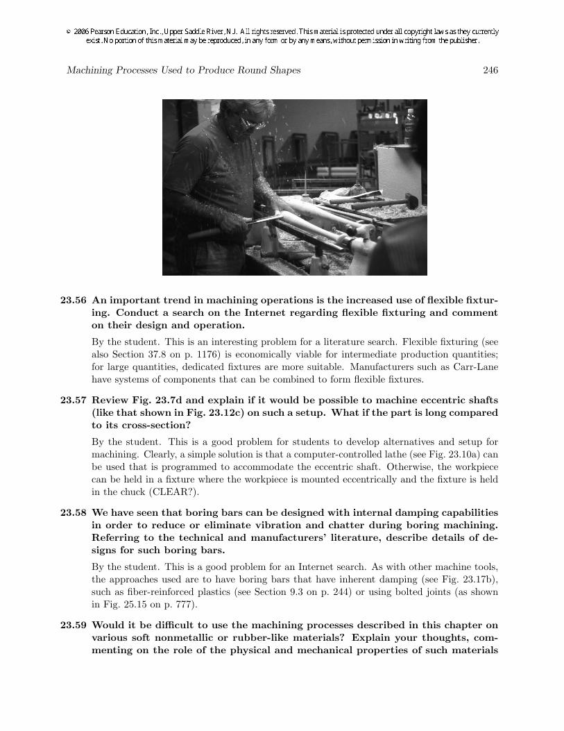
23.55 Describe the machine tool and the fixtures needed to machine baseball bats fromwooden cylindrical stock.
This is an outstanding problem for a literature and/or Internet search. For example, a verygood description of baseball-bat manufacture is contained at www.sluggermuseum.org. Handturning is shown below, although most wooden bats are now made on tracer lathes (p. 691)and CNC lathes.
Machining Processes Used to Produce Round Shapes 246
23.56 An important trend in machining operations is the increased use of flexible fixtur-ing. Conduct a search on the Internet regarding flexible fixturing and commenton their design and operation.
By the student. This is an interesting problem for a literature search. Flexible fixturing (seealso Section 37.8 on p. 1176) is economically viable for intermediate production quantities;for large quantities, dedicated fixtures are more suitable. Manufacturers such as Carr-Lanehave systems of components that can be combined to form flexible fixtures.
23.57 Review Fig. 23.7d and explain if it would be possible to machine eccentric shafts(like that shown in Fig. 23.12c) on such a setup. What if the part is long comparedto its cross-section?
By the student. This is a good problem for students to develop alternatives and setup formachining. Clearly, a simple solution is that a computer-controlled lathe (see Fig. 23.10a) canbe used that is programmed to accommodate the eccentric shaft. Otherwise, the workpiececan be held in a fixture where the workpiece is mounted eccentrically and the fixture is heldin the chuck (CLEAR?).
23.58 We have seen that boring bars can be designed with internal damping capabilitiesin order to reduce or eliminate vibration and chatter during boring machining.Referring to the technical and manufacturers’ literature, describe details of de-signs for such boring bars.
By the student. This is a good problem for an Internet search. As with other machine tools,the approaches used are to have boring bars that have inherent damping (see Fig. 23.17b),such as fiber-reinforced plastics (see Section 9.3 on p. 244) or using bolted joints (as shownin Fig. 25.15 on p. 777).
23.59 Would it be difficult to use the machining processes described in this chapter onvarious soft nonmetallic or rubber-like materials? Explain your thoughts, com-menting on the role of the physical and mechanical properties of such materials
Machining Processes Used to Produce Round Shapes 247
on the machining operation and any difficulties in producing the desired shapesand dimensional accuracies.
By the student. This is a very interesting question and an excellent candidate for a technicalliterature review. Rubberlike materials are difficult to machine mainly because of their lowelastic modulus and very large elastic strains that they can undergo under external forces.Care must be taken in properly supporting the workpiece and minimizing the cutting forces.Note also that these materials become stiffer with lower temperatures, which suggests aneffective cutting strategy.
23.60 With appropriate sketches, describe the principles of various fixturing methodsand workholding devices that can be used for the processes described in this chap-ter. Include three-point locating and three-dimensional workholding for drillingand similar operations.
By the student. This is a good problem and instructive for students to prepare sketches ofvarious clamps and vices in a typical machine shop, if available. Workholding is an art in itselfand many ingenious devices have been developed over the years. A sampling of workholdingdevices can be obtained easily by surveying manufacturers web sites on the Internet.
23.61 Make a comprehensive table of the process capabilities of the machining processesdescribed in this chapter. Using several columns, describe the machine toolsinvolved, type of cutting tools and tool materials used, shapes of parts produced,typical maximum and minimum sizes, surface finish, dimensional tolerances, andproduction rates.
By the student. This is a challenging and comprehensive problem with many possible solu-tions. Some examples of acceptable answers are:
Process Machine tools Cutting-tool Shapes Typicalmaterials sizes
Turning Lathe Assorted; see Axisymmetric 1-12 in.Table 23.4 diameter, 4-48
in. lengthDrilling Lathe, mill Assorted, Circular holes 1-100 mm (50
drill press usually HSS µm possible)Knurling Lathe, mill Assorted, Rough surfaces on Same as in
usually HSS axisymmetric turningparts
23.62 Inspect various utensils in a typical kitchen, and identify the ones that have somesimilarity to the processes described in this chapter. Comment on their principleof operation.
By the student. There are a large number of possible answers, depending on the exposureof the students to different gadgets and their creativity in finding similarities among them.Some examples are:
• Apple and potato peelers that operate in similar fashion as a turning and skiving oper-ation.
Machining Processes Used to Produce Round Shapes 248
• Shaving of butter or chocolate is a process similar to orthogonal or oblique cutting.
• Restaurants will have graters and slicers that are similar to the processes in this chapter,specifically turning operations.
23.63 In Fig. 23.14, we have shown tolerances that can be obtained by the processlisted in the figure. Give specific examples of parts and applications where suchultra-high dimensional accuracy are essential.
By the student. Various answers can be given, depending on the students’ experience andlevel of research performed. Some examples are:
• Drilling and rough turning: Products where the surface finish and tolerances of theseprocesses are acceptable include metal or wooden furniture, automotive engine blocks,and mounting brackets.
• Reaming and broaching: Performed where better quality holes are required such asmounting brackets for helicopter spindles.
• Honing and lapping: Used when drilling and reaming cannot produce a hole with accept-able quality. Example: Automotive cylinders for race cars, where extreme conditionsare routinely encountered.


![A NORTH AMERICAN AUTOMOTIVE STRATEGIC …1].1...and solidification/casting processes other than high-pressure die casting (which is used to produce more than 99 percent of current](https://static.documents.pub/doc/80x56/5aa492717f8b9ac8748c1de1/a-north-american-automotive-strategic-11and-solidificationcasting-processes.jpg)


![CHAPTER 8 Chemicals Based on Propylene · Acrylonitrile [CH2=CHCN] Both fixed and fluid-bed reactors are used to produce acrylonitrile, but most modern processes use fluid-bed systems.](https://static.documents.pub/doc/80x56/60a2840e1933e01c617288d5/chapter-8-chemicals-based-on-propylene-acrylonitrile-ch2chcn-both-fixed-and-fluid-bed.jpg)


