30
Celebrating Our 100th Issue SPECIAL COLLECTOR'S EDITION Vol. 17/No. 100 Classic Cabinet Styk WORKBENCH
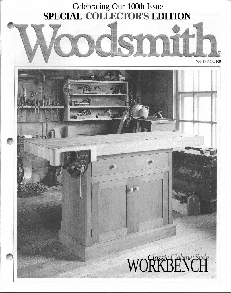
Celebrating Our 100th IssueSPECIAL COLLECTOR'S EDITION
Vol. 17/No. 100
Classic Cabinet StykWORKBENCH
No. 100 August, 1995
EditorExecutive EditorManaging Editor
Assistant Editors
Creative DirectorSenior Illustrators
IllustratorPhotographer
Electronic GraphicsDesign DirectorSenior Designer
Shop ManagerShop Asst/Facilities
Donald B. PeschkeDouglas L. HicksTerry J.StrohmanJon GarbisonMark A. WilliamsTedKralicekDavid KreylingCinda ShambaughDirkVerSteegErich LageCrayola EnglandChris GlowackiKen MunkelKent WelshSteve CurtisSteve Johnson
CIRCULATIONSw6serijotionMancw7ers:SandyBaum,TroyJ.Dowell,Paige Rogers • Assistant Subscription Managers:Shane Francis, Julie Greenlee • Newsstand Manager:Kent A. Buckton
PUBLISHING SERVICESMgr: Gordon Gaippe • Graph. Artist: Cheryl L. Cynor
CORPORATE SERVICESPlanning Director: Jon Macarthy • Controller: RobinHutchinson 'Account.: Laura Thomas • Bookkeeping:Holly Lucas • Production Mgr.: Carol Quijano • Info.Serv. Mgr.: Joyce Moore • Elec. Pub. Coord.: DouglasM. lidster • Network Adm.: Nick Thielen • Admin.Assistants: Cheryl A. Scott, Julia Fish* Receptionist:Jeanne Johnson • Build. Maint: Ken Griffith
WOODSMITH MAIL ORDERArt Dir.: Cindy Jackson • Catalog Prod. Mgr.: BobBaker • Inv. Control/Prod. Mgr.: Mark Mattiussi• Proj. Supplies: Linda Jones • Tech. Supp: Dave Stone• System Operator: Tammy Aldini
CUSTOMER SERVICEManager: Jennie Enos'Team Leader: Karla Cronin• Customer Service Reps.: Jennifer Murphy, JoyKrause, Sara Kono, Anna Cox, Lonnie Algreen,Adam Best, Kristi Andrews
SHIPPING DEPARTMENTSupr: Nancy Johnson • Fulfillment Gloria Sheehan,Chuck Carlson, Sylvia Carey, Larry Prine
WOODSMITH STOREManager: Dave Larson • Assistant Manager: PaulSchneider»Sa£es Staff: Wendell Stone, Pat Lowery• Office Manager: Vicki Edwards
Woodsmith® (ISSN 0164-4114) is published bimonthly(Feb., Apr., June, Aug., Oct., Dec.) by Woodsmith Corp.,2200 Grand, Des Moines, IA 50312.Woodsmith® is a registered trademark of Woodsmith Corp.Copyright© 1995 Woodsmith Corporation. All rights reserved.Subscriptions: Single copy: $3.95. One year subscription (6issues), $19.95. Two years (12 issues), $35.95. (Canada/For-eign add $5 per year, U.S. funds.)Second Class Postage Paid at Des Moines, IA and at addi-tional offices.Postmaster: Send change of address to Woodsmith, Box10718, Des Moines, IA 50350.Subscription Questions? Call 1-800-333-5075, 8:00 amto 5:00 pm, Central Tune, weekdays.E-Mail. Prodigy: EDJE97A, CompuServe: 75330,2301, [email protected]., America Online: Donpeschke.
Printed in U.S.A.
E D I T O R ' S C O L U M N
SawdustIt's still hard to believe that this is the
100th issue of Woodsmith. To me, itjust doesn't seem that long ago that I wasworking on the first issue. I guess timedoes fly when you're having fun.
READERS' GALLERY. To help celebrateour 100th issue, I wanted to do somethingspecial. Something a little different.
So a couple issues back I asked readersto send in photographs of Woodsmith pro-jects they had built. To say that I waspleased with the response would be an un-derstatement. I can't remember the lasttime I had so much fun opening the mail.
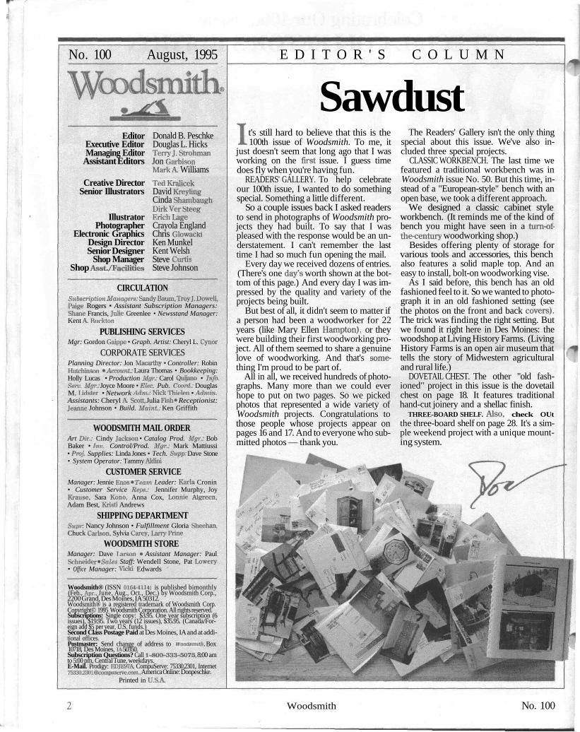
Every day we received dozens of entries.(There's one day's worth shown at the bot-tom of this page.) And every day I was im-pressed by the quality and variety of theprojects being built.
But best of all, it didn't seem to matter ifa person had been a woodworker for 22years (like Mary Ellen Hampton), or theywere building their first woodworking pro-ject. All of them seemed to share a genuinelove of woodworking. And that's some-thing I'm proud to be part of.
All in all, we received hundreds of photo-graphs. Many more than we could everhope to put on two pages. So we pickedphotos that represented a wide variety ofWoodsmith projects. Congratulations tothose people whose projects appear onpages 16 and 17. And to everyone who sub-mitted photos — thank you.
The Readers' Gallery isn't the only thingspecial about this issue. We've also in-cluded three special projects.
CLASSIC WORKBENCH. The last time wefeatured a traditional workbench was inWoodsmith issue No. 50. But this time, in-stead of a "European-style" bench with anopen base, we took a different approach.
We designed a classic cabinet styleworkbench. (It reminds me of the kind ofbench you might have seen in a turn-of-the-century woodworking shop.)
Besides offering plenty of storage forvarious tools and accessories, this benchalso features a solid maple top. And aneasy to install, bolt-on woodworking vise.
As I said before, this bench has an oldfashioned feel to it. So we wanted to photo-graph it in an old fashioned setting (seethe photos on the front and back covers).The trick was finding the right setting. Butwe found it right here in Des Moines: thewoodshop at Living History Farms. (LivingHistory Farms is an open air museum thattells the story of Midwestern agriculturaland rural life.)
DOVETAIL CHEST. The other "old fash-ioned" project in this issue is the dovetailchest on page 18. It features traditionalhand-cut joinery and a shellac finish.
THREE-BOARD SHELF. Also, check OUtthe three-board shelf on page 28. It's a sim-ple weekend project with a unique mount-ing system.
Woodsmith No. 100
A L O O K I N S I D E
ContentsFEATURES
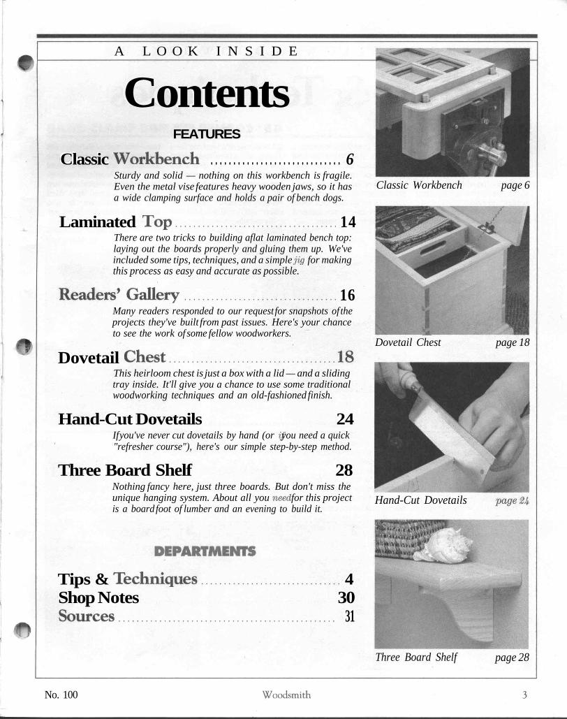
Classic Workbench . . . . . . . . . . . . . . . . . . . . . . . . . . . . . 6Sturdy and solid — nothing on this workbench is fragile.Even the metal vise features heavy wooden jaws, so it hasa wide clamping surface and holds a pair of bench dogs.
Laminated T o p . . . . . . . . . . . . . . . . . . . . . . . . . . . . . . . . . . . . 14There are two tricks to building aflat laminated bench top:laying out the boards properly and gluing them up. We'veincluded some tips, techniques, and a simple jig for makingthis process as easy and accurate as possible.
Readers* G a l l e r y . . . . . . . . . . . . . . . . . . . . . . . . . . . . . . . . . . 16Many readers responded to our request for snapshots of theprojects they've built from past issues. Here's your chanceto see the work of some fellow woodworkers.
Dovetail C h e s t . . . . . . . . . . . . . . . . . . . . . . . . . . . . . . . . . . . . . 1 8This heirloom chest is just a box with a lid — and a slidingtray inside. It'll give you a chance to use some traditionalwoodworking techniques and an old-fashioned finish.
Hand-Cut Dovetails 24If you've never cut dovetails by hand (or if you need a quick"refresher course"), here's our simple step-by-step method.
Three Board Shelf 28Nothing fancy here, just three boards. But don't miss theunique hanging system. About all you need for this projectis a board foot of lumber and an evening to build it.
Tips & T e c h n i q u e s . . . . . . . . . . . . . . . . . . . . . . . . . . . . . . . 4Shop Notes 30S o u r c e s . . . . . . . . . . . . . . . . . . . . . . . . . . . . . . . . . . . . . . . . . . . . . . . . 31
Classic Workbench page 6
-•**,Dovetail Chest page 18
Hand-Cut Dovetails
Three Board Shelf page 28
No. 100 Woodsmith

"7T
F R O M F E L L O W W O O D W O R K E R S
Tips & TechniquesSANDER CONVERSION• Sanding in tight places isabout as much fun as doingtaxes. You could buy an expen-sive detail sander (the kind witha triangle-shaped head), but in-stead I converted my finishingsander into one.
It's easy to do. Just changebases. Simply remove thescrews and take off the old pad.Then use it as a template to
mark the mounting holes for anew base. But here's the bestpart. You can make a new basefit any shape you want.
This new base can be madefrom almost any thin material.But I like V4"-thick Masonite.The self-adhesive sandpaper Iuse seems to stick better.
Jace LaaksoMissoula, Montana
Remove existingbase and installauxiliary base
* Masonite base
Cut base to anyshape you need
45° CORNER CLAMP• I was recently working on adisplay cabinet with a glass frontbuilt at a 45° angle Qike a baywindow). The problem was try-ing to clamp and glue the frontframe pieces together. That'sbecause the frame pieces wereripped at 22^° (half of 45°).
My solution was a two-piececlamping jig. There's a basepiece with an opening cut in it to
match the angle of the miter, seedrawing below. It cradles theworkpiece and keeps it frommoving. A clamping block ontop pushes the workpiece downagainst the angled base. Thatway when the clamp is tight-ened the mitered pieces aresqueezed tight together.
Orville HeitkampBelle Plaine, Minnesota
Base cradles workpiecewhile clamping block
ROUTER FENCE INSERTS• I need a large opening (forclearance) in my router tablefence when using large bits. Buta large opening isn't safe whenrouting small pieces — they canwedge between the bit andfence causing kickback.
To solve this problem, I added
a replaceable insert to my fence.It fills in the space around the bitso small pieces won't get caughtin the opening.
To make an insert for yourfence, simply rout a shallowmortise Qike the mortise for ahinge) around the opening, see
Fig. 1. It's cut a little larger thanneeded for the woodscrews thathold it in place. And just deepenough to equal the thickness ofthe insert. (I used a V8"-thickpiece of Masonite.)
I make an insert for each bit.For a straight bit, simply raise it
in the router table and cut outthe insert, see Fig. 2.
But for profile bits, the bear-ing gets in the way. So first cut aclearance slot in the insert, andthen cut the profile, see Fig. 3.
Mark MuncieIndianapolis, Indiana
1 Cut insert to coveropening in fence
Router table fence
For straight bits, simplyraise the bit to cut a slot
Insert
t
Straight~" bit
FIRST: Cut out slot forbearing clearance
SECOND: Raise profile bit to cutinsert to the same shape
Insert
Profile bit
Woodsmith No. 100
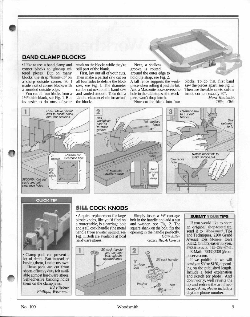
BAND CLAMP BLOCKS• I like to use a band clamp andcorner blocks to glue-up mi-tered pieces. But on manyblocks, the strap "hangs-up" ona sharp outside corner. So Imade a set of corner blocks witha rounded outside edge.
You cut all four blocks from aIW-thick blank, see Fig. 1. Butit's easier to do most of your
work on the blocks while they'restill part of the blank.
First, lay out all of your cuts.Then make a partial saw cut onall four sides to define the blocksize, see Fig. 1. The diametercan be cut next on the band sawand sanded smooth. Then drill a1/4" dia. clearance hole in each ofthe blocks.
Next, a shallowgroove is routedaround the outer edge tohold the strap, see Fig. 2.A tall fence supports the work-piece when rolling it past the bit.And a Masonite base covers thehole in the tabletop so the work-piece won't drop into it.
Now cut the blank into four
blocks. To do that, first bandsaw the pieces apart, see Fig. 3.Then use the table saw to cut theinside corners exactly 90°.
Mark RoutzahnTiffin, Ohio
FIRST: Make partialcuts to divide blankinto four sections
Use band sawto cut outblocksRoll
workpiecepast bitto makegroove
Sawbetween
kerfsTall auxiliary
fence
Wdiameter >clearance hole
Rotate block 90° tomake second cut
Va" Masoniteauxiliary base
SECOND: Cut outcircle and drillclearance holes
QUICK TIP
• Clamp pads can prevent alot of dents. But instead ofbuying them, I make my own.
These pads are cut fromsheets of heavy duty felt avail-able at most hardware stores.Self-adhesive backing holdsthem on the clamp jaws.
Ed FlietnerPhillips, Wisconsin
SILL COCK KNOBS• A quick replacement for largeplastic knobs, like you'd find ona router table, is a carriage boltand a sill cock handle (the metalhandle from a water spigot), seeFig. 1. Both are available at localhardware stores.
Sill cock handleand carnagebolt replaces
studded knob
Simply insert a Vi" carriagebolt in the handle and add a nutand washer, see Fig. 2. Thesquare shank on the bolt, fits theopening in the handle perfectly.
Gary AdlerGassville, Arkansas
SUBMIT YOUR TIPSIf you would like to share
an original shop-tested tip,send it to Woodsmith, Tipsand Techniques, 2200 GrandAvenue, Des Moines, Iowa50312. Or if it's easier for you,FAX it to us at: 515-282-6741.
E-Mail: 75330,[email protected].
If we publish it, we willsend you $30 to $150, depend-ing on the published length.Include a brief explanationand sketch (or photo). Anddon't worry, we'll rewrite thetip and redraw the art if nec-essary. Also, please include adaytime phone number.
No. 100 Woodsmith
F E A T U R E P R O J E C T
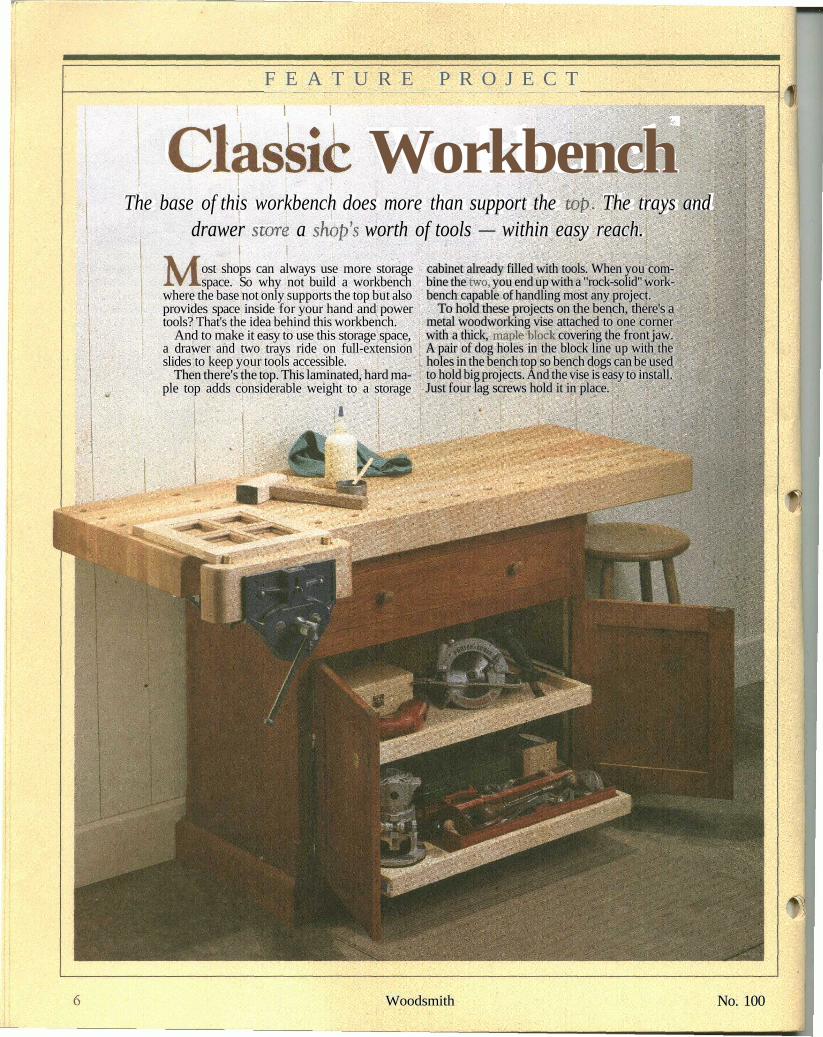
Class& WorkbenchThe base of this workbench does more than support the top. The trays and
drawer store a shop's worth of tools — within easy reach.
ost shops can always use more storagespace. So why not build a workbench
where the base not only supports the top but alsoprovides space inside for your hand and powertools? That's the idea behind this workbench.
And to make it easy to use this storage space,a drawer and two trays ride on full-extensionslides to keep your tools accessible.
Then there's the top. This laminated, hard ma-ple top adds considerable weight to a storage
cabinet already filled with tools. When you com-bine the two, you end up with a "rock-solid" work-bench capable of handling most any project.
To hold these projects on the bench, there's ametal woodworking vise attached to one cornerwith a thick, maple-block covering the front jaw.A pair of dog holes in the block line up with theholes in the bench top so bench dogs can be usedto hold big projects. And the vise is easy to install.Just four lag screws hold it in place.
Woodsmith No. 100

Construction Details
Record #52'/2 ED visewith quick-releasemechanism
Made fromstrips of 8/4 hard mapleglued face-to- face
BASE:Outside case is made fromcherry hardwood and plywood
Interior framing anddrawers made from maplehardwood and plywood
NOTE:Complete cutting diagramand materials list on page 13
CROSS SECTIONEND VIEW
———— 22%" —————
Drawer
wood knobs
Frame andpanel doors
Hardwoodkickboard
_ Ball catchfor doors
Note: Drawer and traysare mounted with full-extension drawer slides
Trays-
VISE DETAILCROSS SECTION
Solid steelhandle
The Record #52V2 ED vise withwood jaws has an open capacity of 9%"
Frame andpanel back
- 19V2"-
Woodspacer
_ Quick-release lever allows ^- Vise mounted with (4)vise to open and close freely V2" x 3" lag screws
HARDWARE LIST• (1) Record #52V2 ED Vise• (2)#14x2" RhWoodscrews• (4) 1/2" x 3" Lag Screws. (4) 1/2" Washers• (4) 1V4"-dia. Wood Knobs• (2pr.)2" x13/s" Ball-tipped
Hinges• (2) Ball Catches
(8) #4 x 1/2" Fh Woodscrews(4) 1/4" x 3" Lag Screws(4)V4" Washers(20) #8 x 13/4" Fh Woodscrews(36) #8 x 11/4" Fh Woodscrews(16) #8 x 1" Fh Woodscrews(3 pr.) 16" Full-ExtensionDrawer Slides
No. 100 Woodsmith
a pair of case sides (J) are cut next, see Fig.2. These are just 3/4M-thick pieces of plywoodwith 3/8M rabbets cut on both edges. Eachrabbet forms a tongue that fits into thegrooves already cut in the stiles, see Fig. 2a.
Then assemble the sides and frames andglue and clamp the case together. Aftertightening your clamps, check that the caseremains square.
CHAMFER STILES. With the case assem-bled, I routed a decorative stopped chamferon all four corners, see Fig. 3. (It works bestto rout this chamfer in several passes.)
CLEATS. Next, I turned my attention tothe inside of the case, starting at the bottomand working my way up.
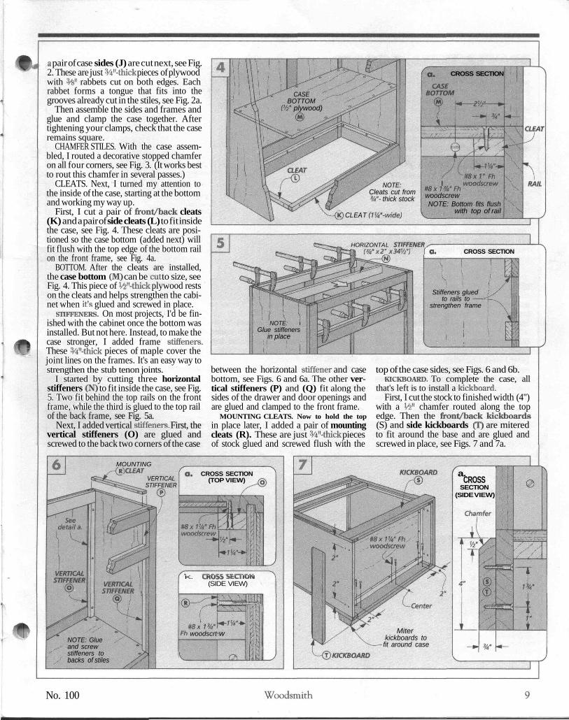
First, I cut a pair of front/back cleats(K) and a pair of side cleats (L) to fit insidethe case, see Fig. 4. These cleats are posi-tioned so the case bottom (added next) willfit flush with the top edge of the bottom railon the front frame, see Fig. 4a.
BOTTOM. After the cleats are installed,the case bottom (M) can be cut to size, seeFig. 4. This piece of V£"-thick plywood restson the cleats and helps strengthen the cabi-net when it's glued and screwed in place.
STIFFENERS. On most projects, I'd be fin-ished with the cabinet once the bottom wasinstalled. But not here. Instead, to make thecase stronger, I added frame stiffeners.These W-thick pieces of maple cover thejoint lines on the frames. It's an easy way tostrengthen the stub tenon joints.
I started by cutting three horizontalstiffeners (N) to fit inside the case, see Fig.5. Two fit behind the top rails on the frontframe, while the third is glued to the top railof the back frame, see Fig. 5a.
Next, I added vertical stiffeners. First, thevertical stiffeners (O) are glued andscrewed to the back two corners of the case
CROSS SECTION
CASEBOTTOM
(%" plywood)
FhI woodscrew
#8x1%"FhwoodscrewNOTE: Bottom fits flush
with top of rail
NOTE:Cleats cut from%"- thick stock
-<K) CLEAT (I'A'-wide)
HORIZONTAL STIFFENER^(%'x 2'x 34W) la CROSS SECTION
Stiffeners glued !to rails to
strengthen frame
NOTE: iGlue stiffeners
in place
between the horizontal stiffener and casebottom, see Figs. 6 and 6a. The other ver-tical stiffeners (P) and (Q) fit along thesides of the drawer and door openings andare glued and clamped to the front frame.
MOUNTING CLEATS. Now to hold the topin place later, I added a pair of mountingcleats (R). These are just 3/4"-thick piecesof stock glued and screwed flush with the
top of the case sides, see Figs. 6 and 6b.KICKBOARD. To complete the case, all
that's left is to install a kickboard.First, I cut the stock to finished width (4")
with a V£" chamfer routed along the topedge. Then the front/back kickboards(S) and side kickboards (T) are miteredto fit around the base and are glued andscrewed in place, see Figs. 7 and 7a.
MOUNTINGR)Ci£A7
VERTICALSTIFFENER
NOTE: Glueand screwstiffeners tobacks of stiles
O. CROSS SECTION(TOP VIEW)
K. l_KUii iCtllUIH(SIDE VIEW)
#8x 13/4"Fh woodscrt
^
^ \ \\V-N
•«-7!4-*-w
f^
iltl
ftfi?^
l l
a.CROSSSECTION
(SIDE VIEW)
Miterkickboards to
fit around case
No. 100 Woodsmith

DRAWER, TRAYS, & DOORSOnce the outside of the case was finished, Iturned my attention to the inside to add apair of trays and a drawer.
CLEATS. I planned on using full-extensionslides for the drawer and trays. But theslides couldn't be screwed to the case sidesbecause the frame stiffeners got in the way.So I added slide cleats (U) to provide amounting surface for the slides, see Fig. 8.
These cleats are 3/4M-thick pieces of stockscrewed to the frame stiffeners. They don'textend all the way to the front of the case,otherwise the doors and drawer wouldn'tclose all the way, see Fig. 8a. To get theneeded clearance, I installed the cleats Vie"back from the inside face of the front frame.
TRAYS. With the cleats installed in thecase, I began work on the trays. I decided touse pull-out trays because it makes it a loteasier to get at your tools — especially theones at the back.
To determine the size of the front/backtray pieces, first measure the opening be-tween the cleats (mine was SOVfe"). Thensubtract 1" for the thickness of two slidesand Vfe" for the lap joints at the corners. Find-ing the size of the tray sides is easier. Itmatches the length of your slides (16").
I used these measurements to cut thetray front/back (V) and sides (W) to fin-ished size, see Fig. 9. (My tray was 16" x29 W.) Next, I cut a 3/4"-wide rabbet at bothends of the sides for lap joints to join the traypieces together, see Fig. 9a. Then a groovecan be routed on the inside face of all thetray pieces to hold a W-thick piece of ply-
CROSS SECTION(SIDE VIEW)
® SLIDE CLEAT
NOTE:Install cleatsand slidesVK" from
front frame
Screw cleatsto verticalstiffeners
16" full-extensiondrawer
slide
NOTE:Slides mount to cleatswith screws
wood for a bottom, see Fig. 9b.Making the tray bottom (X) from W ply-
wood keeps it from sagging when loadedwith tools. It should fit snug in the traypieces before you glue the tray together.
DRAWER. With the trays complete, thedrawer is built next. What's different is howthe drawer is held together. It has hand-cutdovetails for strength and durability.
Here again, you want to measure the
opening before making any cuts. Then cutthe drawer front/back (Y) and sides (Z)to finished size and lay out and cut the dovetails, see Figs. 10 and lOa. For more on cut-ting dovetails, refer to page 24.
Now rout a groove to accept a drawer bot-tom, see Fig. lOb. Once again, I used VzH-thick plywood for added strength. Then cutthe bottom (AA) to fit tight and glue andclamp the drawer together.
TRAY SIDE
TRAY FRONT
a.
SIDE
V2"
TOPVIEW
' FRONT/BACK-
END VIEW
Size grooveto matchplywood v / J~
L^' II
10 Woodsmith No. 100
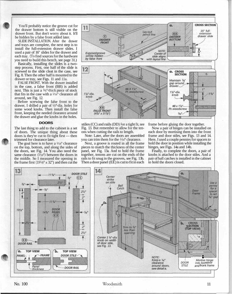
You'll probably notice the groove cut forthe drawer bottom is still visible on thedrawer front. But don't worry about it. It'llbe hidden by a false front added later.
SLIDE INSTALLATION. After the drawerand trays are complete, the next step is toinstall the full-extension drawer slides. Iused a pair of 16" slides for the drawer andeach tray. (To find sources for the hardwareyou need to build this bench, see page 31.)
Basically, installing the slides is a two-step process. First, one half of the slide isscrewed to the slide cleat in the case, seeFig. 8. Then the other half is mounted to thedrawer or tray, see Figs. 11 and lla.
FALSE FRONT. With the drawer installedin the case, a false front (BB) is addednext. This is just a 3/4M-thick piece of stockthat fits in the case with a Vie" clearance allaround, see Fig. 12.
Before screwing the false front to thedrawer, I drilled a pair of V2"-dia. holes forsome wood knobs. Then install the falsefront, keeping the needed clearance aroundthe drawer and glue the knobs in the holes.
DOORSThe last thing to add to the cabinet is a setof doors. The unique thing about thesedoors is they're cut to fit tight first — thentrimmed for clearance later.
The goal here is to have a Vie" clearanceon the top, bottom, and along the sides ofthe doors, see Fig. 14. You also need thesame clearance (Vie") between the doors inthe middle. So I measured the opening inthe frame first (19 Vs" x 32") and then cut the
16" full-extension
drawer slide
NOTE:Center of
slide alignswith layout fine
Exposed groovewill be hiddenby false front
Maintain Viegap aroundarawer
stiles (CC) and rails (DD) f or a tight fit, seeFig. 13. But remember to allow for the ten-ons when cutting the rails to length.
Note: Later, after the doors are assembledyou can trim them for the Vie" clearance.
Next, a groove is routed in all the framepieces to match the thickness of the centerpanel, see Fig. 13a. And to hold the frametogether, tenons are cut on the ends of therails to fit snug in the grooves, see Fig. 13b.Then a door panel (EE) is cut to fit in each
frame before gluing the door together.Now a pair of hinges can be installed on
each door by mortising them into the frontframe and door stiles, see Figs. 13 and 14.Here, I used a couple pennies for spacers tohold the door in position while installing thehinges, see Figs. 14a and 14b.
Finally, to complete the doors, a pair ofknobs is attached to the door stiles. And apair of ball catches is installed in the cabinetto hold the doors closed.
Center 1 W-diaknob on widthof door stile,see Fig. 13.
NOTE:Keep a 'clearancearound doors,see detail a.
fb- s(T<
x '> VJ\\1_* 1=f- •
CROSS jECTIONM> VIEW) ',
\ \ '• /
^/P
P
K/'\
^ ———— , \i Mortise hinge
DOOR int0 D0th doorSTILE anci front frame
No. 100 Woodsmith 11

BENCH TOPAfter the cabinet is complete, Iworked on the bench top next.Note: For more on building lami-nated tops, refer to page 14.
STRIPS. This laminated topconsists of 13 bench top strips(FF). These strips are l3/4"-thickpieces of stock cut to a finishedlength of 62" and a rough width of39/i6". Later, the top is sanded toits final thickness (3W), see ex-ploded view at right.
ALIGNMENT HOLES. To keep allthe strips aligned when gluingthem together, I drilled holes forshort lengths of ̂ "-dia. dowels,see detail 'a.' But remember, thetwo outside strips (1 and 13) onlyhave holes on one face.
DOG HOLES. You could gluethe bench top strips togethernow. But I didn't want to wrestlewith a heavy top. And there arestill a few things left to do.
First, a series of 3/4"-dia. dogholes are drilled in the top forbench dogs, see detail 'b.' Refer topage 31 for sources of benchdogs. Then rout a Vs" chamferaround each hole to soften the sharp edges.
ROUNDOVER. Next, the corners on thetwo outside strips are rounded over, see de-tail 'c.' Note: But don't round the corner atthe end where the vise will be mounted.
NOTCH. There's one more thing to do be-fore gluing the top together. And that's torout a pocket in the front strip for mountinga metal vise. The back jaw of the vise slipsinto this pocket. This way, the metal jaw is
CROSS SECTION (BENCH STRIPS) c. CORNER DETAIL
BENCH TOPSTRIP
J CROSS SECTION(FACE BLOCK)
U CROSS SECTION(BENCH STRIPS)
ft'-dia.dog hole
Sana to finalthickness of 3Vi
covered by the front strip, and you have along, smooth surface to clamp against, seeFigs. 15 and 18.
GLUE-UP. With the pocket routed, thebench top strips can be glued together, seeFig. 16. Later, I used a belt sander to sandthe top and bottom faces smooth.
BENCH TOP INSTALLATION. Once the topis sanded, it can be attached to the cabinet.But first I routed an Vs" chamfer around the
bottom edge, see Fig. 17. Then position thetop so it's centered side to side with a IVi"overhang on the back, see Fig. 17a. Nowdrill shank holes through the cleats in thecabinet and use 3" lag screws with washersto hold the bench top in place.
VISEWith the top secured to the cabinet, the visecan be installed next. I used a Record vise,
15 Rout pocfcetin bench stripfor vise jaw
9Vis"
CROSS SECTION
nTop edge
Frontstrip (Ato.7.)
IDo not usealignment dowelsin first two holes
17 LaminatedTop
FRONT VIEW
Install top so it's centeredside-to-side on cabinet
NOTE:Before mounting top to base
rout Vs" chamferaround bottom edges
CROSS SECTION '-*'(SIDE VIEW) chamfer-^
washer~- VA" x 3" lag screw
12 Woodsmith No. 100

model #521^ ED. It features a quick-releaseon the front jaw, so it can be moved in or outwith the touch of a lever.
VISE INSTALLATION. But before installingthe vise, I added a spacer block (GG) tomake the top of the face block (added next)level with the bench top. This 3/4"-thickpiece of stock is cut to match the mountingplate on the vise (in my case 5" x 9"). Thendrill VS"-dia. mounting holes through the
spacer block and screw the block and viseto the bench top, see Fig. 18.
FACE BLOCK. After installing the vise, Icovered the front jaw with a thick mapleblock. This block protects your workpieceand also spreads the clamping pressureover a larger area.
To make the face block (HH), glue to-gether a couple pieces of stock to create a2W-thick laminated piece, see exploded
view and detail 'd' on page 12. Then drill two3/4M-dia. dog holes in the face block andround over the two outside corners. Nowrout a Vs" chamfer on the bottom edge andattach the face block to the vise, see Fig. 18.
To complete the bench top, I used a hand-held router to rout a Vfe" chamfer on the topedge (including the vise), see Fig. 19. It re-moves the sharp edge left over from sand-ing the top smooth. Q
Rout Vs" chamferaround top edges
NOTE:Chamfertop edgeof face blockwith viseclosed
MATERIALS LIST CUTTING DIAGRAMCASE
Case Bottom (1)
ABCDEFGHIJKLMNOPQRSTU Slide Cleats (6)V Tray Fr./Bk. (4)W Tray Sides (4)X Tray Bottoms (2)Y Dr. Fr./Bk. (2)Z Dr. Sides (2)
3 /4x2 -32V53/4 X 2 - 323/43/4 X 67/8 - 323/43/4 X 3 - 243/8V4ply. - 15V4X243/83 / 4 X 2 - 3 2 V 5
Bk. Stiles (2)Bk. Upper Rail (1)Lower Rail (1)Center divider (1)Back Panels (2)Fr. Stiles (2)Fr. Upper Rails (2) 3/4 x 2 - 323/4Fr. Lower Rail (1) 3/4 x 43/8 . 323/4Filler Strips (1)Case Sides (2)Fr./Bk. Cleats (2)Side Cleats (2)
1/4 x 3/8 - 60 (rgh)3/4 ply. -171/4X32V53/4 X 1 V4 - 341/i
3 / 4 X 1 V 4 - 1 4
1/2 ply. -16V2 x 341/5Hor. Stiffeners (3) 3/4 x 2 - 34V2Vert. Stiffeners (2) 3/4 x 11/4 - 28Vs (rgh)Vert. Stiffeners (2) % x 1V4 - 5V5 (rgh)Vert. Stiffeners (2) 3/4 x 1V4 -191/5 (rgh)Mntg. Cleats (2) 3 / 4x1V4-15Fr./Bk Kickbrds. (2)3/4 x 4 - 37V5Side Kickbrds. (2) 3 / 4 X4-19Vi
3/4X13/4-161/23/4X13/4-293/4X13/J-16
1/2 ply. -15'/4 x 283/43/4 X 43/8 - 29V23/4X43/8-16
AA Dr. Bottom (1) V2 ply. - 151/4 x 283/4BB D r. False Fr. (1) 3/4 x 47/3 .317/3CC Door Stiles (4) 3/4 x 21/5 -19VsDD Door Rails (4) 3/4 x 2 Vs - 113/4EE Door Panels (2) 1/4 ply. -113/4 x 14%
BENCH TOPFF Bench. Strips (13) 13/4X39/16 - 62GG Spacer Block (1) 3/4 x 5 . gHH Face Block (1) 2V2X4V8-14
%" x 9"- 96" Cherry ( 6 Bd. Ft.)T
T
S —
S -7
B '' '/G ///G /.'/
/// / /. '/'// //' /// / ///%" x 7"- 96" Maple (4.7 Bd. Ft.)
—————— N ————————————— w ——————
—————————— O ———— —— u —————— u
I 0 ! /^ f /
u —— Y/////-, — . .. .. . . V /•////%"x4"-96" Maple ( 2.7 Bd. Ft.) ̂ —— — - '——————— V ————————— ——————— V ———————— ——— W ——— ——— W ———— '/'\/ / 1%" x 6"- 96" Maple (4 Bd. Ft)
YL 1 L
YI ft I ft
2 Z //,K ' V
%" x 5"- 72" Cherry (2.5 Bd. Ft.)AA
FF
' / / /' / / /
V x 7"- 72" Cherry (3.5 Bd. Ft)
C BB
K%" x 5"- 72" Cherry (2.5 Bd. Ft.)
•/.,,? »,,.,%
%"x6"- 72" Cherry (3 Bd. Ft.)CCCC
1%"x5"- 96" Maple (6.7 Bd.
CC DD DDCC DD DD
Ft.)FF
l%"x8"-72" Maple ( 6 boards @ 7.5 Bd. Ft. ea.)FFFF
//// ALSO NEED:'/// Vt"x48"x48"
Vi' x 48" x 48"/ ///, •'/, Maple plywood
3/n" x48" x48"Cherry plywood
'// //
HH HH X^
GG •- ^ N %" thickness\
''/'/' //' \3A" thickness
No. 100 Woodsmith 13
W O O D W O R K I N G T E C H N I Q U E
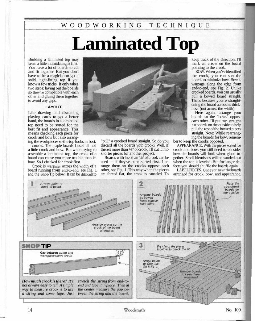
Laminated TopBuilding a laminated top mayseem a little intimidating at first.You have a lot of boards to cutand fit together. But you don'thave to be a magician to get asolid, tight-fitting top if youknow a few tricks. It only takestwo steps: laying out the boardsso they're compatible with eachother and gluing them togetherto avoid any gaps.
LAYOUTLike drawing and discardingplaying cards to get a betterhand, the boards in a laminatedtop need to be sorted for thebest fit and appearance. Thismeans checking each piece forcrook and bow but also arrang-ing the workpieces so the top looks its best.
CROOK. The maple boards I used all hada little crook and bow. But when trying toassemble a laminated top, the crook of aboard can cause you more trouble than itsbow. So I checked for crook first.
Crook is warpage across the width of aboard running from end-to-end, see Fig. 1and the Shop Tip below. It can be difficult to
"pull" a crooked board straight. So do youdiscard all the boards with crook? Well, ifthere's more than Vs" of crook, I'll cut it intoshorter pieces for another project.
Boards with less than Vfc" of crook can beused — if they've been sorted first. I ar-range them so the crooks oppose eachother, see Fig. 1. This way when the piecesare forced flat, the crook is canceled. To
keep track of the direction, I'llmark an arrow on the boardpointing to the crook.
BOW. When you've identifiedthe crook, you can sort theboards to minimize bow. Bow iswarpage along the edge fromend-to-end, see Fig. 2. Unlikecrooked boards, you can usuallypull a bowed board straight.That's because you're straight-ening the board across its thick-ness (not across the width).
Here again, arrange yourboards so the "bows" opposeeach other. I'll put my straight-est boards on the outside to helppull the rest of the bowed piecesstraight. Note: While rearrang-ing the boards for bow, remem-
ber to keep the crooks opposed.APPEARANCE. With the pieces sorted for
crook and bow, you still need to considerhow the boards will look when glued to-gether. Small blemishes will be sanded outwhen the top is leveled. But for larger de-fects you should shuffle the boards again.
LABEL PIECES. Once you have the boardsarranged for crook, bow, and appearance,
Arrows point tocrook of board
Arrange pieces so thecrook of the board
alternates
Arrange boardsso bowedfaces opposeeach other
Place thestraightestboards on
the outside
SHOP TIPGap between string andworkpiece shows crook
How much crook is there? It'snot always easy to tell. A simpleway to measure crook is to usea string and some tape. Just
stretch the string from end-to-end and tape it in place. Then atthe center measure the gap be-tween the string and the board.
Dry clamp the piecestogether to check the fit
Arrow pointsto face thatfits in jig -̂
14 Woodsmith No. 100

C E L E B R A T I N G O N E H U N D R E D I S S U E S O 1
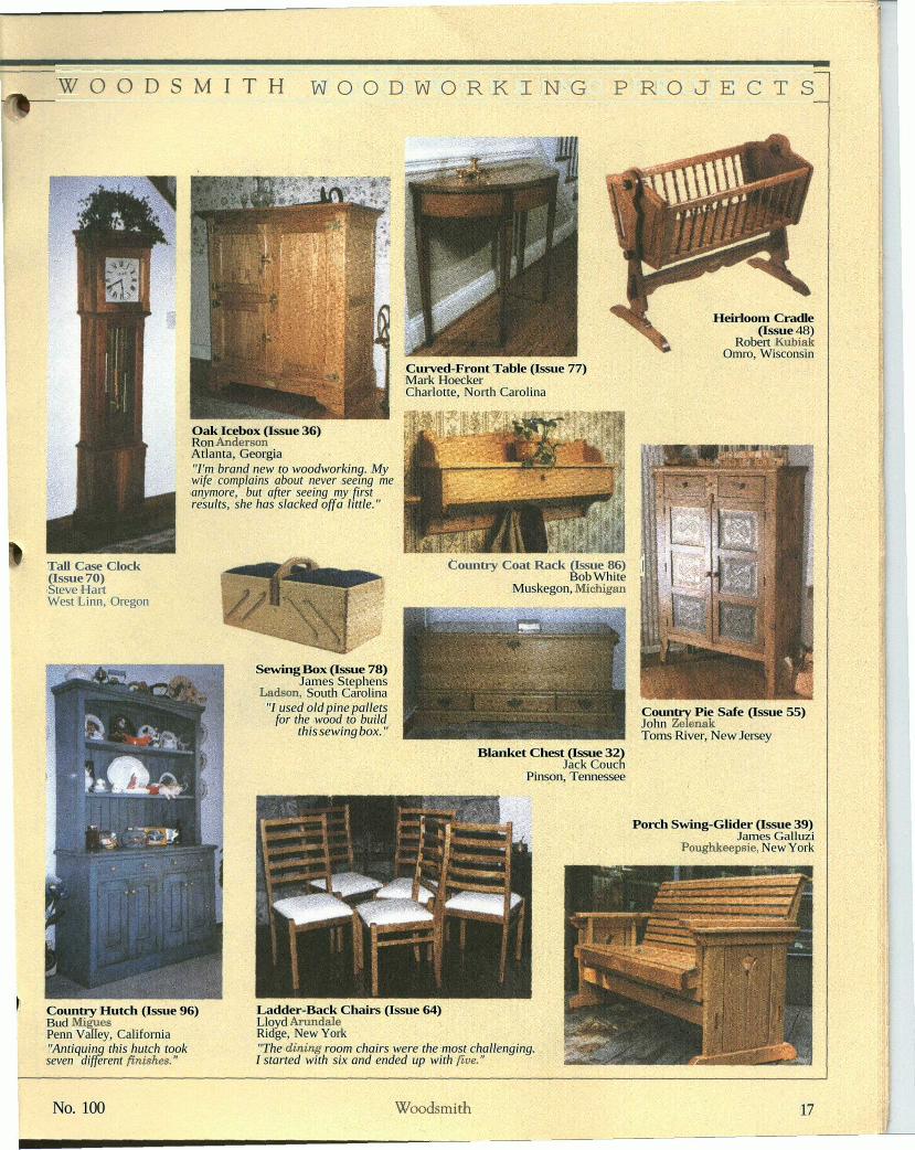
Readers'Gallery
Over the years, a lot of readers have sentus photos of projects they've built from
Woodsmith. Plus, we've received hundreds moresince I announced this gallery in the Sawdustcolumn a couple of issues ago.
Of course, we couldn't include every photo.What you see here is a sampling of the crafts-manship and ingenuity of our readers. Some fol-lowed our plans closely; others adapted themquite a bit. We hope you enjoy seeing thesecompleted projects as much as we have.
Classic Workbench (Issue 50)Donald JacobyArvada, Colorado
Oak Rocking Chair (Issue 84)Tom BakerSan Diego, CaliforniaEditor's Note: Tom used blackwalnut to build his oak rocker.
Saw Cabinet (Issue 47)David KerskiEden Prairie, Minnesota"This photo was taken inmy library because myshop was too small."
Regulator Clock(Issue 36)Chris HellmuthMiddle Island, New York
Armoire (Issue 67) Armoire (Issue 67)Bill Evans Bob SchuchardRehoboth, Massachusetts Fort Collins, ColoradoEditor's Note: Most readers customize our projects to some extent. Bill Euan'scherry armoire looks just like ours but has drawers inside. Bob Schuchard'spine armoire has a scalloped base and raised panels on the sides.
Pedestal Desk (Issue 79)R. E. Corbett, Jr.Wilmington, North Carolina"This is the only piece of furniturein our house that both childrenhave requested when I die."
Classic Roadster(Issue 51)Frank PinoEdwardsville, Kansas
Garden Bench (Issue 93)Bill KilpatrickEnniskerry, County Wicklow, Ireland
Rocking Horse (Issue 65)William MurrayLondon, Ontario
16 Woodsmith No. 100
W O O D S M I T H W O O D W O R K I N G P R O J E C T S
Heirloom Cradle(Issue 48)
Robert KubiakOmro, Wisconsin
Curved-Front Table (Issue 77)Mark HoeckerCharlotte, North Carolina
Oak Icebox (Issue 36)Ron AndersonAtlanta, Georgia"I'm brand new to woodworking. Mywife complains about never seeing meanymore, but after seeing my firstresults, she has slacked off a little."
ill
Tall Case Clock(Issue 70)Steve HartWest Linn, Oregon
Country Coat Rack (Issue 86) |Bob White
Muskegon, Michigan
Sewing Box (Issue 78)James Stephens
Ladson, South Carolina"I used old pine pallets
for the wood to buildthis sewing box."
Country Pie Safe (Issue 55)John ZelenakToms River, New Jersey
Blanket Chest (Issue 32)Jack Couch
Pinson, Tennessee
Porch Swing-Glider (Issue 39)James Galluzi
Poughkeepsie, New York
Country Hutch (Issue 96)Bud MiguesPenn Valley, California"Antiquing this hutch tookseven different finishes."
Ladder-Back Chairs (Issue 64)Lloyd ArundaleRidge, New York"The dining room chairs were the most challenging.I started with six and ended up with five."
No. 100 Woodsmith 17
H E I R L O O M P R O J E C T
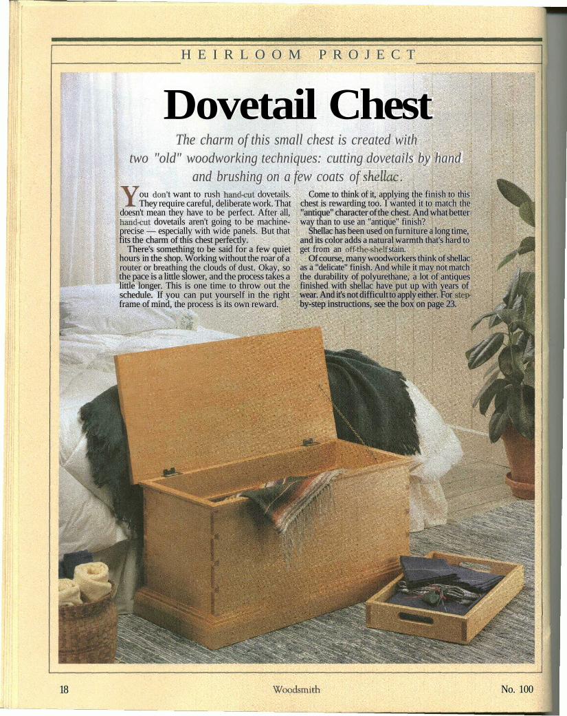
Dovetail ChestThe charm of this small chest is created with
two "old" woodworking techniques: cutting dovetails by handand brushing on a few coats of shellac.
You don't want to rush hand-cut dovetails.They require careful, deliberate work. That
doesn't mean they have to be perfect. After all,hand-cut dovetails aren't going to be machine-precise — especially with wide panels. But thatfits the charm of this chest perfectly.
There's something to be said for a few quiethours in the shop. Working without the roar of arouter or breathing the clouds of dust. Okay, sothe pace is a little slower, and the process takes alittle longer. This is one time to throw out theschedule. If you can put yourself in the rightframe of mind, the process is its own reward.
Come to think of it, applying the finish to thischest is rewarding too. I wanted it to match the"antique" character of the chest. And what betterway than to use an "antique" finish?
Shellac has been used on furniture a long time,and its color adds a natural warmth that's hard toget from an off-the-shelf stain.
Of course, many woodworkers think of shellacas a "delicate" finish. And while it may not matchthe durability of polyurethane, a lot of antiquesfinished with shellac have put up with years ofwear. And it's not difficult to apply either. For step-by-step instructions, see the box on page 23.
18 Woodsmith No. 100
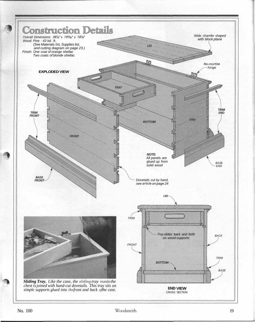
Overall Dimensions: 38Vs" x 79%" x 78'/s"Wood: Pine - 43 bd. ft.
(See Materials list. Supplies list,and cutting diagram on page 23.)
Finish: One coat of orange shellacTwo coats of blonde shellac
EXPLODED VIEW
Wide chamfer shapedwith block plane
NOTE:All panels areglued up fromsolid wood
BASEFRONT Dovetails cut by hand,
see a/t/c/e on page 24
LID-
BASEEND
Sliding Tray. Like the case, the sliding tray inside thechest is joined with hand-cut dovetails. This tray sits onsimple supports glued into the front and back of the case.
TRIM
FRONT
-Tray slides back and forthon wood supports
BOTTOM-
END VIEWCROSS SECTION
BACK
TRIM
BASE
No. 100 Woodsmith 19
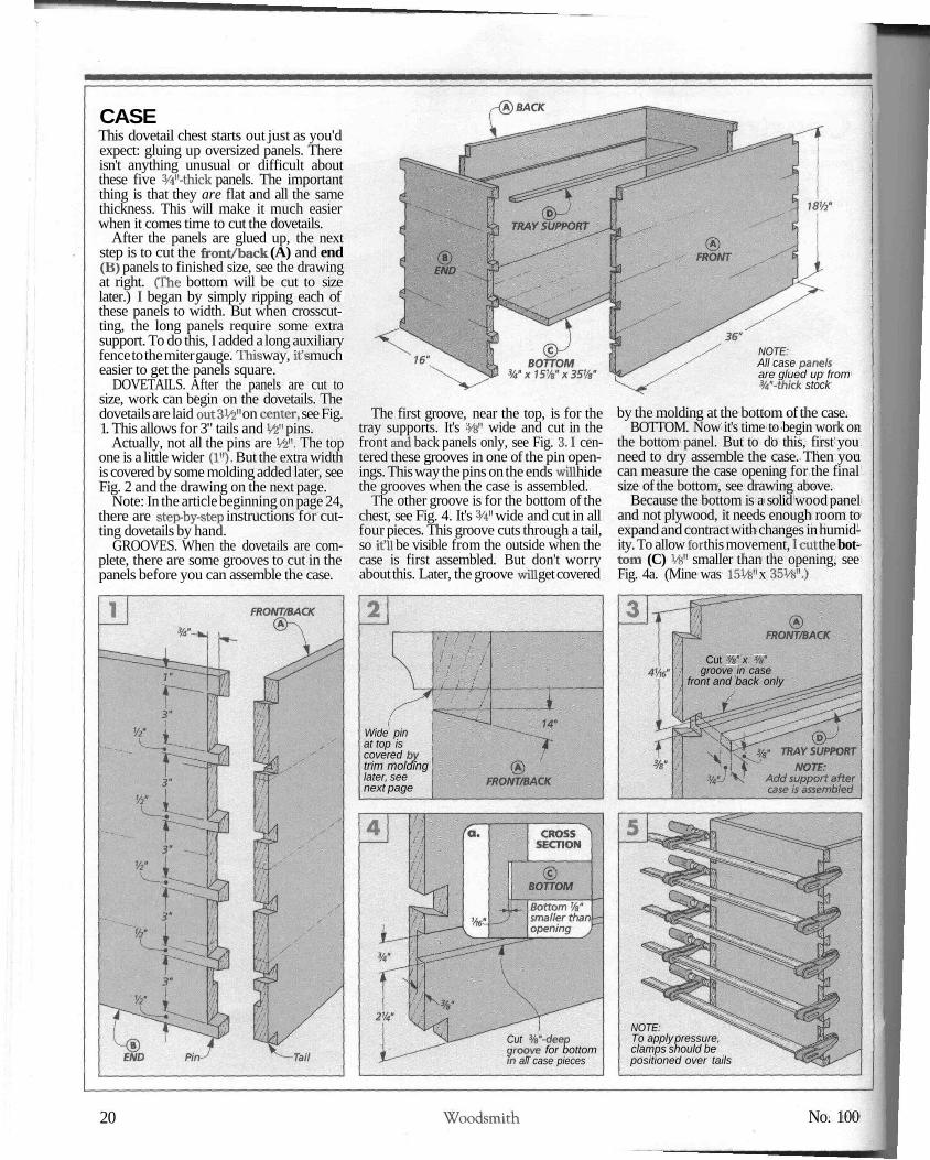
CASEThis dovetail chest starts out just as you'dexpect: gluing up oversized panels. Thereisn't anything unusual or difficult aboutthese five 3/4"-thick panels. The importantthing is that they are flat and all the samethickness. This will make it much easierwhen it comes time to cut the dovetails.
After the panels are glued up, the nextstep is to cut the front/back (A) and end(B) panels to finished size, see the drawingat right. (The bottom will be cut to sizelater.) I began by simply ripping each ofthese panels to width. But when crosscut-ting, the long panels require some extrasupport. To do this, I added a long auxiliaryfence to the miter gauge. This way, it's mucheasier to get the panels square.
DOVETAILS. After the panels are cut tosize, work can begin on the dovetails. Thedovetails are laid outSW on center, see Fig.1. This allows for 3" tails and Vfe" pins.
Actually, not all the pins are V£". The topone is a little wider (1"). But the extra widthis covered by some molding added later, seeFig. 2 and the drawing on the next page.
Note: In the article beginning on page 24,there are step-by-step instructions for cut-ting dovetails by hand.
GROOVES. When the dovetails are com-plete, there are some grooves to cut in thepanels before you can assemble the case.
The first groove, near the top, is for thetray supports. It's %" wide and cut in thefront and back panels only, see Fig. 3.1 cen-tered these grooves in one of the pin open-ings. This way the pins on the ends will hidethe grooves when the case is assembled.
The other groove is for the bottom of thechest, see Fig. 4. It's 3/4" wide and cut in allfour pieces. This groove cuts through a tail,so it'll be visible from the outside when thecase is first assembled. But don't worryabout this. Later, the groove will get covered
NOTE:All case panelsare glued up from3/4"-thick stock
by the molding at the bottom of the case.BOTTOM. Now it's time to begin work on
the bottom panel. But to do this, first youneed to dry assemble the case. Then youcan measure the case opening for the finalsize of the bottom, see drawing above.
Because the bottom is a solid wood paneland not plywood, it needs enough room toexpand and contract with changes in humid-ity. To allow for this movement, I cut the bot-tom (C) Vfe" smaller than the opening, seeFig. 4a. (Mine was 15W x 35Vs".)
Cut 3/s" x %"groove in case
front and back only
Wide pinat top iscovered bytrim moldinglater, seenext page
NOTE:To apply pressure,clamps should bepositioned over tails
Cut 3/a"-deepgroove for bottomin all case pieces
20 Woodsmith No. 100
CASE ASSEMBLY. After the bottom panelis ready, you can glue the case together, seeFig. 5. (But don't use glue on the bottom.)This takes quite a bit of time, so I used whiteglue. It gives you a little more time to work.
While the glue is drying, cut two W-widetray supports (D) to fit in the grooves in-side the case, see Fig. 3. This time, I wantedthe glue to set up fast, so I used yellow glue.That way, I didn't have to worry about usingclamps. Applying a little hand pressure fora minute or two was all it took.
At this point, the case is essentially com-plete. But if there are pins or tails protrud-ing, you'll need to sand them flush with thesides of the case, see the Shop Tip at right.Once that's done, all that's left is to add thebase and some trim molding around the topand bottom, see the drawing below.
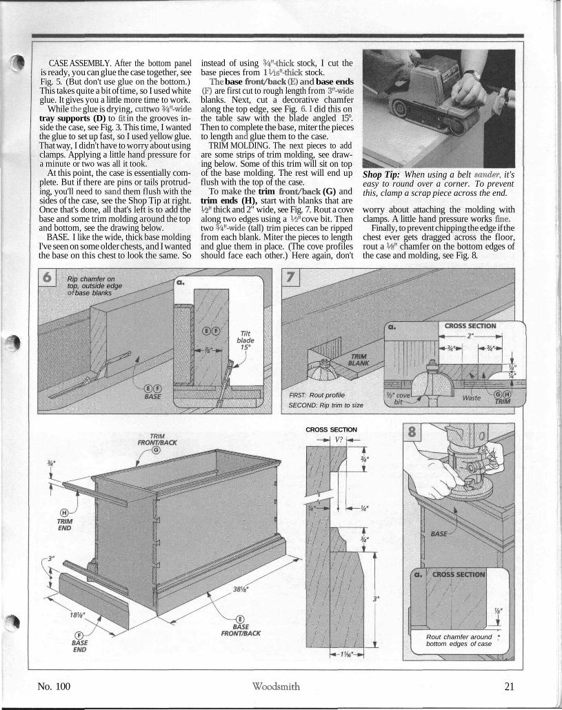
BASE. I like the wide, thick base moldingI've seen on some older chests, and I wantedthe base on this chest to look the same. So
instead of using 3/4"-thick stock, I cut thebase pieces from 1 Vi6M-thick stock.
The base front/back (E) and base ends(F) are first cut to rough length from 3"-wideblanks. Next, cut a decorative chamferalong the top edge, see Fig. 6.1 did this onthe table saw with the blade angled 15°.Then to complete the base, miter the piecesto length and glue them to the case.
TRIM MOLDING. The next pieces to addare some strips of trim molding, see draw-ing below. Some of this trim will sit on topof the base molding. The rest will end upflush with the top of the case.
To make the trim front/back (G) andtrim ends (H), start with blanks that areW thick and 2" wide, see Fig. 7. Rout a covealong two edges using a W cove bit. Thentwo 3/4M-wide (tall) trim pieces can be rippedfrom each blank. Miter the pieces to lengthand glue them in place. (The cove profilesshould face each other.) Here again, don't
Shop Tip: When using a belt sander, it'seasy to round over a corner. To preventthis, clamp a scrap piece across the end.
worry about attaching the molding withclamps. A little hand pressure works fine.
Finally, to prevent chipping the edge if thechest ever gets dragged across the floor,rout a W chamfer on the bottom edges ofthe case and molding, see Fig. 8.
Rip chamfer ontop, outside edgeof base blanks
FIRST: Rout profileSECOND: Rip trim to size
TRIMFRONT/BACK
CROSS SECTIONV?
Rout chamfer around *bottom edges of case
No. 100 Woodsmith 21

pLIDNow that the case is complete, I startedwork on the lid, see drawing at right. Justlike the other parts of the case, this meansyou need to glue up another panel. But thethickness of this panel is different: it's IHe".
Since you lift the lid from the edges, Iwanted it to overhang the case a bit. So todetermine the size of the lid (I), measurethe case (including the trim) and cut the lidpanel 1" longer and wider.
CHAMFER. I also wanted the lid to havethe same chamfer that's around the base.But the panel is too long to stand on end onthe table saw. So I used a block plane.
Before planing, lay out the edges of thechamfer, see Fig. 9. Then plane down tothese lines, starting with the ends of the lid.To avoid chipout, skew the plane slightly sothe cut shears off thin shavings.
HINGES. When the chamfer is cut, mountthe lid to the case. To do this, I used a specialhinge. It has an offset barrel and doesn't re-quire a mortise, see Fig. 10.
To mount the hinges, first screw them tothe case. Next, set the lid on top of the caseand center it side-to-side and front-to-back.Then simply trace around the barrels of thehinges on the bottom of the lid. Now removethe lid and hinges. Then screw the hingesto the lid and reattach the hinges to the case.
IID SUPPORT CHAIN. The last thing to doto the lid is add a 15"-long piece of brasschain to the inside of the case, see Fig. 10.This prevents the lid from dropping back.
Safety Note: If children will be openingand closing this lid, you should protect theirfingers by installing a lid support. (Forsources, see page 31.)
#8x%brass roundhead screw
SHELLAC
When choosing a finish for this chest, Iwanted a warm, "aged" color. But instead oftrying to mimic an old finish, I decided touse the real thing: shellac.
For this chest, I applied one coat of or-ange shellac. The orange shellac gives thewood its warm color — and it doesn't blotchlike a normal stain will. But more than onecoat makes the wood too dark.
So to keep the color lighter but still addmore protection, I applied two more coats ofanother "grade" of shellac: blonde shellac.(Shellac comes in several grades, see page31.) Actually, this isn't a different type ofshellac. It has just been purified more, sothere's not much color.
Shellac comes ready-to-use or in flakesthat must be dissolved in alcohol. (See page31, for sources.) Once dissolved, it beginsto slowly deteriorate. So, I use the flakes andmix my own. This way, I know it's fresh.
Though any alcohol will work, I dissolveshellac in denatured alcohol. Shellac ismixed in "pound cuts" — the number ofpounds of flakes to a gallon of alcohol. Forthis chest I used a 2 Ib. cut. But I only mixedup a pint of each grade (which requires 4 oz.of shellac flakes). And don't worry about be-ing precise. Just get it in the ballpark.
Shellac doesn't dissolve like Kool-Aid. Ittakes several hours or more. Pour the flakesinto a non-metal container. (The shellac re-acts to metal.) Then pour in the alcohol andstir it. Let it set a bit Then stir it again. It'sa good idea to strain the shellac a few timesbefore using it, see photo.
Before applying the first coat of shellac, Isanded the dovetail chest to 220-grit be-cause the soft grain of pine tends to raisewhen shellac is applied.
To apply shellac, I use a natural bristlebrush. The only trick is not to work the fin-
ish too much with the brush. The shellacdries fast, so you can apply another coat af-ter about three hours. Note: If the shellacseems to be drying too quickly, then thin ita little with more alcohol.
I sanded the first coat lightly with 400-gritpaper. Then after the two coats of blondeshellac were applied, I rubbed out the finishwith 600-grit paper.
22 Woodsmith No. 100
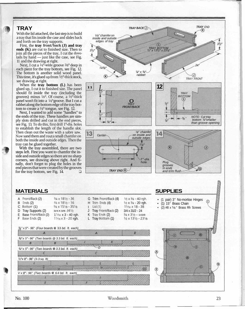
TRAYWith the lid attached, the last step is to builda tray that fits inside the case and slides backand forth on the tray supports.
First, the tray front/back (J) and trayends (K) are cut to finished size. Then tojoin all the pieces of the tray, I cut the dove-tails by hand — just like the case, see Fig.11 and the drawing at right.
Next, I cut a W-wide groove %" deep ineach piece for the tray bottom, see Fig. 12.The bottom is another solid wood panel.This time, it's glued up from ̂ "-thick stock,see drawing at right.
When the tray bottom (L) has beenglued up, I cut it to finished size. The panelshould fit inside the tray (including thegrooves) minus Vfe". Of course, a VS"-thickpanel won't fit into a W groove. But I cut arabbet along the bottom edge of the tray bot-tom to create a Vi" tongue, see Fig. 12.
Next, I wanted to add some "handles" tothe ends of the tray. These handles are sim-ply slots drilled and cut in the end pieces,see Fig. 13. To do this, first drill l"-dia. holesto establish the length of the handle slot.Then clean out the waste with a sabre saw.Now sand them and rout a small chamfer onboth the inside and outside edges. Then thetray can be glued together.
With the tray assembled, there are twosteps left. First you want to chamfer the in-side and outside edges so there are no sharpcorners, see drawing above right. And fi-nally, don't forget to plug the holes in theend pieces that were created by the groovesfor the tray bottom, see Fig. 14. Q
TRAY BACK TRAY END
Va" chamfer oninside and outside
edges of tray
TRAY BOTTOM'/2"x13'/2"x231A'
TRAY FRONT
11 L_
2V2-0
TRAYFRONT/BACK
12TRAY
BOTTOM
k }, „ NOTE: Cut tray/s bottom Va'smaller
than groove opening
W chamferon inside andoutside edges
MATERIALS SUPPLIESA Front/Back (2)B Ends (2)C Bottom (1)D Tray Supports (2)E Base Front/Back (2)F Base Ends (2)
3/4X18V*-363/4x181/4-16
3/4 X 3/8 - ;
1 Vie x 3 - 40 rgh.1Vi6 x3 -20 rgh.
G Trim Front/Back (4)H Trim Ends (4)I Lid(1)J Tray Front/Back (2)K Tray Ends (2)L Tray Bottom (1)
1/5x3/4-40 rgh.1/4 x 3/4 - 20 rgh.1V16X18-383/4 x 31/2 - 243/4 X 3'/4- 143/8
1/4x1314-231/8
• (1 pair) 3" No-mortise Hinges• (1) 15" Brass Chain• (2) #8 x 5/&" Brass Rh Screws
" x 5"- 96" (Four boards @ 3.3 bd. ft. each)A A B ''/.
%" x 5"- 96" (Two boards @ 3.3 bd. ft. each)B B
%" x 5"- 96" (Two boards @ 3.3 bd. ft. each)
'/2"x8"-96" (3.3 sq. ft)1 L
'////////, '/, '///
L
'̂/////, '/////. ty
L'//////////;/ ////////
V x 8"- 96" (Two boards @ 6.6 bd. ft. each)
®
®
No. 100 Woodsmith 23
W O O D W O R K I N G T E C H N I Q U E
Hand^Cut DovetailsA step-by-step approach to cutting dovetails in wide panels.
Plus, some techniques for assembly and a few troubleshooting tips.
Which comes first,the pins or the
tails? Frankly, you cancut them either way, butI start with the pins. It'show I was taught andhow I always cut them.
WHICH IS WHICH? Butmaybe I'm jumping thegun. After all, when look-ing at this interlockingjoint, it can be hard to tellwhich one is the tail andwhich is the pin.
The trick is to look atjust the face of the board,not the ends, see Fig. 1.The tails flare out — likea dove's tail. And fromthe face, the pins arestraight, sort of like boxjoints. The pins slide inbetween the tails, but un-like box joints, they canonly slide in one direc-tion. The angled sides act as wedges, so youcan't pull them apart any other way.
PINS FIRST. So why do I cut the pins first?There are a couple reasons. First, I think thepins are easier to cut. But it's also easier tocut them accurately. (And if they don't endup perfectly square to the baseline, it's easyto clean them up so they are.) This is impor-tant because after the pins are cut, you'll usethem to lay out the positions of the tails.(Laying out the tails from the pins is alsoeasier than marking the pins from the tails.)
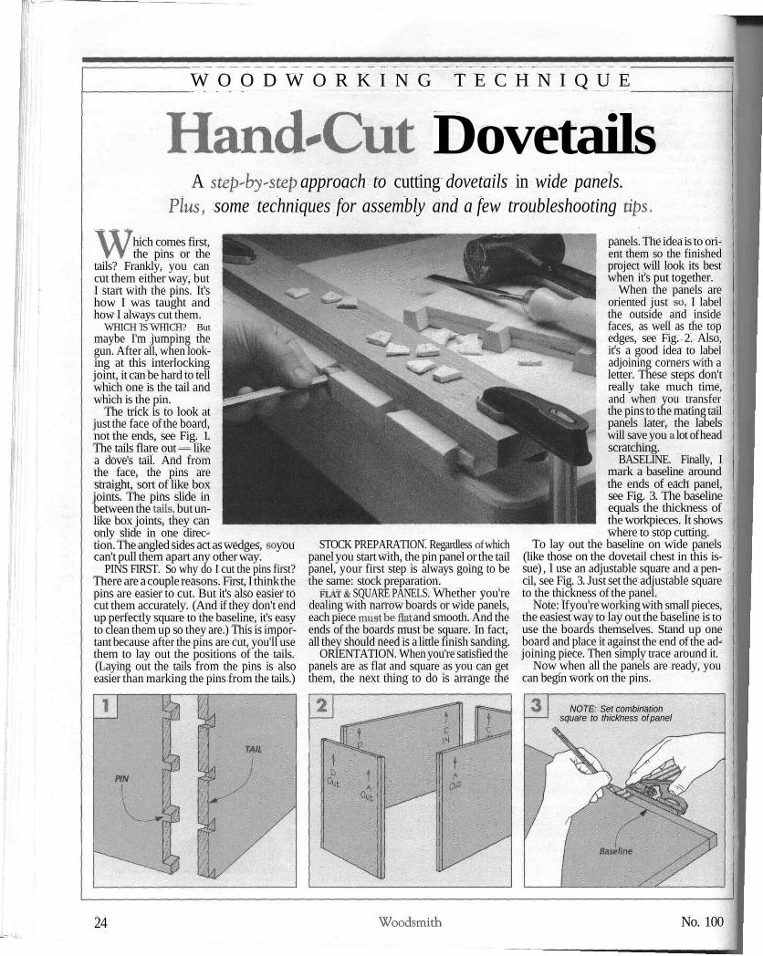
STOCK PREPARATION. Regardless of whichpanel you start with, the pin panel or the tailpanel, your first step is always going to bethe same: stock preparation.
FLAT & SQUARE PANELS. Whether you'redealing with narrow boards or wide panels,each piece must be flat and smooth. And theends of the boards must be square. In fact,all they should need is a little finish sanding.
ORIENTATION. When you're satisfied thepanels are as flat and square as you can getthem, the next thing to do is arrange the
panels. The idea is to ori-ent them so the finishedproject will look its bestwhen it's put together.
When the panels areoriented just so, I labelthe outside and insidefaces, as well as the topedges, see Fig. 2. Also,it's a good idea to labeladjoining corners with aletter. These steps don'treally take much time,and when you transferthe pins to the mating tailpanels later, the labelswill save you a lot of headscratching.
BASELINE. Finally, Imark a baseline aroundthe ends of each panel,see Fig. 3. The baselineequals the thickness ofthe workpieces. It showswhere to stop cutting.
To lay out the baseline on wide panels(like those on the dovetail chest in this is-sue) , I use an adjustable square and a pen-cil, see Fig. 3. Just set the adjustable squareto the thickness of the panel.
Note: If you're working with small pieces,the easiest way to lay out the baseline is touse the boards themselves. Stand up oneboard and place it against the end of the ad-joining piece. Then simply trace around it.
Now when all the panels are ready, youcan begin work on the pins.
NOTE: Set combinationsquare to thickness of panel
24 Woodsmith No. 100
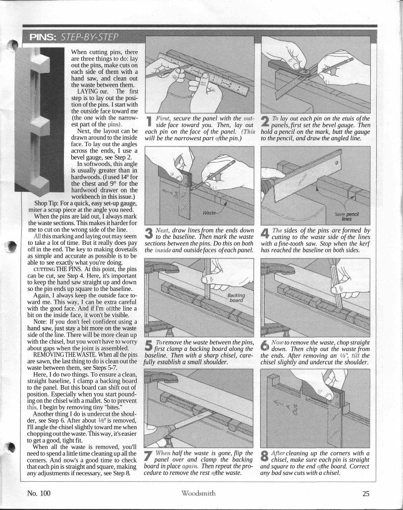
PINS: STEP-BY-STEPWhen cutting pins, thereare three things to do: layout the pins, make cuts oneach side of them with ahand saw, and clean outthe waste between them.
LAYING our. The firststep is to lay out the posi-tion of the pins. I start withthe outside face toward me(the one with the narrow-est part of the pins).
Next, the layout can bedrawn around to the insideface. To lay out the anglesacross the ends, I use abevel gauge, see Step 2.
In softwoods, this angleis usually greater than inhardwoods. (I used 14° forthe chest and 9° for thehardwood drawer on theworkbench in this issue.)
Shop Tip: For a quick, easy set-up gauge,miter a scrap piece at the angle you need.
When the pins are laid out, I always markthe waste sections. This makes it harder forme to cut on the wrong side of the line.
All this marking and laying out may seemto take a lot of time. But it really does payoff in the end. The key to making dovetailsas simple and accurate as possible is to beable to see exactly what you're doing.
CUTTING THE PINS. At this point, the pinscan be cut, see Step 4. Here, it's importantto keep the hand saw straight up and downso the pin ends up square to the baseline.
Again, I always keep the outside face to-ward me. This way, I can be extra carefulwith the good face. And if I'm off the line abit on the inside face, it won't be visible.
Note: If you don't feel confident using ahand saw, just stay a bit more on the wasteside of the line. There will be more clean upwith the chisel, but you won't have to worryabout gaps when the joint is assembled.
REMOVING THE WASTE. When all the pinsare sawn, the last thing to do is clean out thewaste between them, see Steps 5-7.
Here, I do two things. To ensure a clean,straight baseline, I clamp a backing boardto the panel. But this board can shift out ofposition. Especially when you start pound-ing on the chisel with a mallet. So to preventthis, I begin by removing tiny "bites."
Another thing I do is undercut the shoul-der, see Step 6. After about Vfe" is removed,I'll angle the chisel slightly toward me whenchopping out the waste. This way, it's easierto get a good, tight fit.
When all the waste is removed, you'llneed to spend a little time cleaning up all thecorners. And now's a good time to checkthat each pin is straight and square, makingany adjustments if necessary, see Step 8.
1 First, secure the panel with the out-side face toward you. Then, lay out
each pin on the face of the panel. (Thiswill be the narrowest part of the pin.)
2 To lay out each pin on the etuis of thepanels, first set the bevel gauge. Then
hold a pencil on the mark, butt the gaugeto the pencil, and draw the angled line.
Waste - Save pencillines
3 Next, draw lines from the ends downto the baseline. Then mark the waste
sections between the pins. Do this on boththe inside and outside faces of each panel.
4 The sides of the pins are formed bycutting to the waste side of the lines
with a fine-tooth saw. Stop when the kerfhas reached the baseline on both sides.
5 To remove the waste between the pins,first clamp a backing board along the
baseline. Then with a sharp chisel, care-fully establish a small shoulder.
6 Now to remove the waste, chop straightdown. Then chip out the waste from
the ends. After removing an %", tilt thechisel slightly and undercut the shoulder.
7 When half the waste is gone, flip thepanel over and clamp the backing
board in place again. Then repeat the pro-cedure to remove the rest of the waste.
8 After cleaning up the corners with achisel, make sure each pin is straight
and square to the end of the board. Correctany bad saw cuts with a chisel.
No. 100 Woodsmith 25

TAILS: STEP-BY-STEP
ill
After the pins are com-plete, it's time to work onthe tails. I laid out the pinswith a ruler and a pencil,but the tails are different.They need to be cut to fitthe pins. So instead of us-ing a ruler, I mark thetails directly from thepins. This way, they willmatch them perfectly.
LAYING OUT. To lay outthe tails, the first step is toset the tail panel on theworkbench with the in-side face up. Then standthe pin panel on top so thetwo panels form a corner.These panels should beflush at the ends and theedges with both insidefaces toward each other.
Here's where all thatmarking at the beginningreally helps. It's impor-
tant that the corresponding corners matchwhen laying out the tails. And both panelsshould be oriented correctly.
Shop Tip: To help the panel stand upright,I clamp a piece of scrap to the panel with thepins before setting it on the tail panel, seeStep 1. This also helps remove any slightcupping that may be in the panel.
Now that the tails are marked on the in-side face, the lines can be transferredaround the panel to the outside face, seeSteps 34. Drawing the straight lines acrossthe ends of the panel is easy. But to transferthe angles to the outside face, you'll need touse the bevel gauge again.
To be safe, I don't just draw the same an-gle I used to draw the pins. Instead, I checkeach angle on the inside face, adjust thebevel gauge if necessary, and then transferthis angle to the outside face.
CUTTING THE TAILS. Cutting the tails isdifferent than cutting the pins. This time,the saw isn't straight up and down — it's an-gled instead, see Step 5. This means startingthe cut is a little trickier. So I usually startmore toward the waste side of the line.(Mark the waste sections on the tail piecesif you haven't done so yet.) This leaves mewith more to clean up, but the dovetails fittogether without any gaps.
REMOVING THE WASTE. With all the kerfscut, the last thing to do is remove the waste.
But this time, start with the dovetail sawand remove the waste sections for the pinsat the top and bottom of the panel, see Step6. Then clean up the shoulders with a chisel.
Now you can clean out the rest of thewaste between the tails. There's nothingtricky here. There's just not quite as muchroom to work as with the pins, see Steps 7-8.
I To lay out the tails from the pins, firstset the tail panel on the bench with the
inside face up. Then set the pin panel ontop so mating edges align.
2 Now, make sure the two panels areflush at both the end and the edges.
Then carefully trace the pins onto the tailpanel using a sharp pencil.
3 Next, to extend the lines around thepanel, draw parallel lines across the
ends. To do this accurately, position thepencil. Then slide the try square up to it.
4 Now transfer the angles on the insideface to the outside face. Adjust the
bevel gauge to match the angle on the in-side face. Then draw it on the outside face.
5 To form the sides of the tails, hold thesaw at an angle and begin cutting,
staying on the waste side of the line. Stopwhen the kerf reaches the baseline.
6 To remove the waste for the pins atboth the top and bottom, use the saw,
cutting from the edges toward the firsttail. Then clean up the cuts with a chisel.
7 Now to remove the waste between thetails, use the same procedure as the
pins. Begin by clamping a backing boardto the panel and establishing a shoulder.
8 Remove half the waste. Then flip thepanel over and repeat the process. If
the saw cut didn't follow the line, use achisel to clean up the tails.
26 Woodsmith No. 100

FITTING & ASSEMBLYAt this point, the joint can be assembled. Butfirst, you need to do some fitting.
FITTING. To get the joint to fit, you'reprobably going to need to remove a little ma-terial from either the tails or the pins. But tosee just where to remove this material, thejoint should be dry assembled (as much aspossible), see photo at right.
But don't force it. If you do, the pins at thetop and bottom can split from the pressure.The goal is a fit that can be dry assembledwith a few light taps of a mallet.
With the joint dry assembled as much aspossible, take a close look at each pin anddovetail. You should be able to see wherethe joint is binding. And when you pull thejoint apart, the tight spots will also be bur-nished slightly. To make these areas easierto see, I like to mark them with a pencil, seethe photo at right.
CHISEL. There are a couple ways to fit thedovetails. To remove a lot of material, youcan pare it away with a chisel, see Fig. 1.
This removes the wood pretty fast, but it'salso easy to remove too much material.
SANDING STICK. So I often use a littlesanding stick, see Fig. 2. Basically, this is athin piece of scrap wood with some adhe-sive-backed sandpaper attached. I bevel theedges to match the angle of the tails. Thisway, I can sand right into the corner.
ASSEMBLY. When all the joints fit, thecase (or drawer) is ready to be assembled,see Fig. 3.1 use white glue when assemblinglarge cases. It has a longer set-up time thanyellow glue, which helps with all the smallfaces that need to be glued.
I usually apply glue just to the sides of thepins and tails. I don't bother gluing the base-line since it's end grain.
Clamping up dovetails usually takes a lit-tle preparation. You only want to apply pres-sure to the tails (not the pins).
This isn't a problem with wide dovetailslike those on the chest. But if you don't havemany clamps, you can distribute the clamp-
NOTE: Scrap piece withadhesive-backed
sandpaper on bottomside only
Use sharpchisel to
carefully pareaway material
Beveledges tofit intocorners
TROUBLESHOOTINGIt's a good feeling when those pins finallyslide into the tails. But sometimes the jointisn't quite perfect
PROTRUDING TAILS* PINS. One commonproblem is when either the tails or pins stickout. But this is easily corrected with a littlesanding, see the box on page 21. And ifthere's too much to sand off quickly, you can
ing pressure evenly across the joint with aspecial clamping block, see Fig. 3. (Thisblock also works when the clamp head isbigger than the tails, as on a drawer.) LI
Apply pressureto tail panel only
Notched clampingblock distributespressure evenly
add an auxiliary base to your router and routthem flush, see page 30.
GAPS BETWEEN DOVETAILS. Gaps are amuch bigger problem. For instance, youmight have a gap between a tail and a pin (orbetween several tails and pins). This can befixed, but once again, you'll need to get outyour hand saw.
The idea is to cut an even kerf throughthe gap, see Fig. 1. Then glue a spline in thekerf to "patch" it, see Fig. la.
GAPS AT BASELINE. There's another pos-sible gap you might run into: a gap along thebaseline of the tails. Here the cut was toodeep. The solution is to use wedges to fill thegaps, see Fig. 2.
SECOND: Glue splinein kerf and trim flush
To fill baselinegap, glue in—wedges andtrim flush
No. 100 Woodsmith 27
W E E K E N D P R O J E C T
ThreeBoardShelf
This evening projectmakes use of a unique,
invisible hanging system.
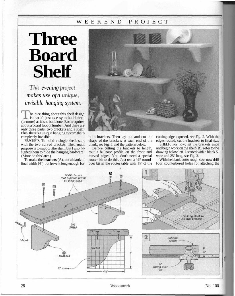
The nice thing about this shelf designis that it's just as easy to build three
(or more) as it is to build one. Each requiresabout a board foot of lumber. And there areonly three parts: two brackets and a shelf.Plus, there's a unique hanging system that'scompletely invisible.
BRACKETS. To build a single shelf, startwith the two curved brackets. Their mainpurpose is to support the shelf, but I also de-signed them to hide the hanging hardware.(More on this later.)
To make the brackets (A), cut a blank tofinal width (4") but leave it long enough for
NOTE: Do notrout bullnose profile
on these edges
both brackets. Then lay out and cut theshape of the brackets at each end of theblank, see Fig. 1 and the pattern below.
Before cutting the brackets to length,rout a bullnose profile on the front andcurved edges. You don't need a specialrouter bit to do this. Just use a V5" round-over bit in the router table with %" of the
e
cutting edge exposed, see Fig. 2. With theedges routed, cut the brackets to final size.
SHELF. For now, set the brackets asideand begin work on the shelf (B), refer to thedrawing below left. I started with a blank 5"wide and 25" long, see Fig. 3.
With the blank cut to rough size, now drillfour counterbored holes for attaching the
Use long blank tocut two brackets
Vi* squares
28 Woodsmith No. 100
dia. x W deepcounterbore
dia. x %" cteep A>o/e
Router \fence ~\ \ "~
J^V]
NOTE:Strike 12"
radius fromcenter of shelf
NOTE:Rout slot inmultiple passesRaise bit to cut
through auxiliary base
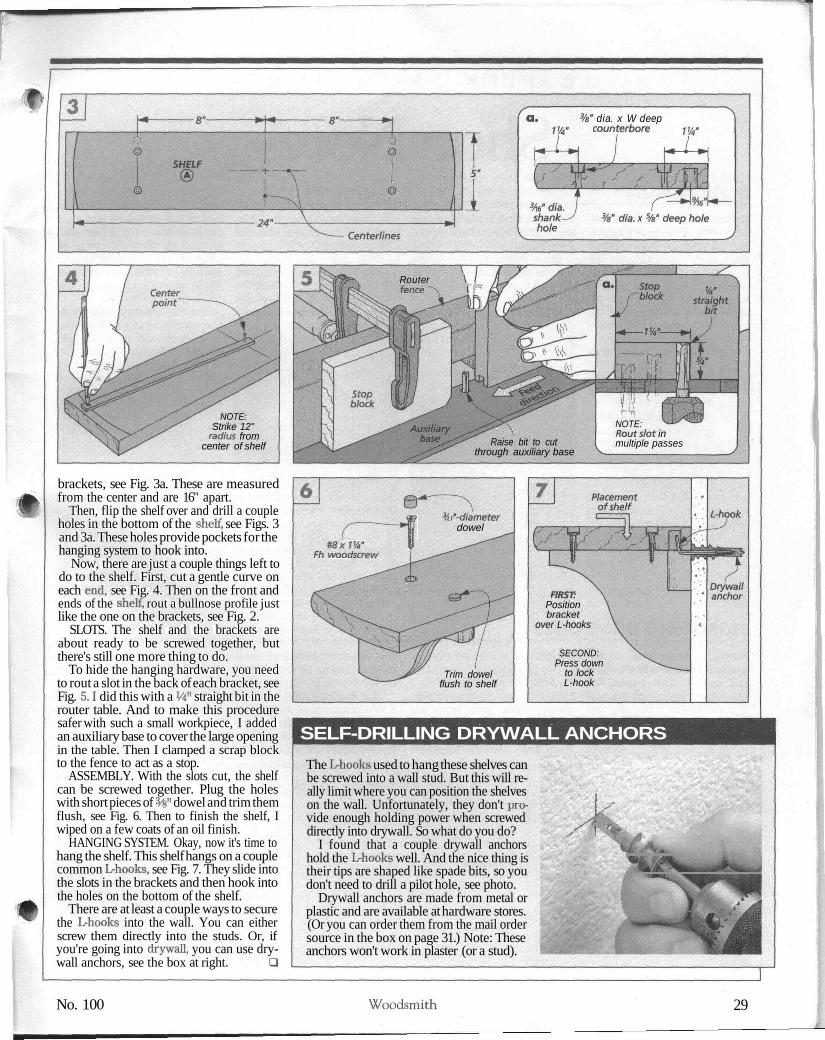
brackets, see Fig. 3a. These are measuredfrom the center and are 16" apart.
Then, flip the shelf over and drill a coupleholes in the bottom of the shelf, see Figs. 3and 3a. These holes provide pockets for thehanging system to hook into.
Now, there are just a couple things left todo to the shelf. First, cut a gentle curve oneach end, see Fig. 4. Then on the front andends of the shelf, rout a bullnose profile justlike the one on the brackets, see Fig. 2.
SLOTS. The shelf and the brackets areabout ready to be screwed together, butthere's still one more thing to do.
To hide the hanging hardware, you needto rout a slot in the back of each bracket, seeFig. 5.1 did this with a Vi" straight bit in therouter table. And to make this proceduresafer with such a small workpiece, I addedan auxiliary base to cover the large openingin the table. Then I clamped a scrap blockto the fence to act as a stop.
ASSEMBLY. With the slots cut, the shelfcan be screwed together. Plug the holeswith short pieces of %" dowel and trim themflush, see Fig. 6. Then to finish the shelf, Iwiped on a few coats of an oil finish.
HANGING SYSTEM. Okay, now it's time tohang the shelf. This shelf hangs on a couplecommon L-hooks, see Fig. 7. They slide intothe slots in the brackets and then hook intothe holes on the bottom of the shelf.
There are at least a couple ways to securethe L-hooks into the wall. You can eitherscrew them directly into the studs. Or, ifyou're going into drywall, you can use dry-wall anchors, see the box at right. Q
<&r————*
#8x1'/4" 9Fh woodscrew
<"-diameterdowel
Trim dowelflush to shelf
FIRST:Positionbracket
over L-hooks
SECOND:Press down
to lockL-hook
SELF-DRILLING DRYWALL ANCHORSThe L-hooks used to hang these shelves canbe screwed into a wall stud. But this will re-ally limit where you can position the shelveson the wall. Unfortunately, they don't pro-vide enough holding power when screweddirectly into drywall. So what do you do?
I found that a couple drywall anchorshold the L-hooks well. And the nice thing istheir tips are shaped like spade bits, so youdon't need to drill a pilot hole, see photo.
Drywall anchors are made from metal orplastic and are available at hardware stores.(Or you can order them from the mail ordersource in the box on page 31.) Note: Theseanchors won't work in plaster (or a stud).
^Ki|M||̂ u|H |̂taHBH|
No. 100 Woodsmith 29

S O M E T I P S F R O M O U R S H O P
Shop NotesDOVETAIL JIG• The timing couldn't havebeen better for receiving a dove-tail jig design from JeffreyKern of Benicia, California. Wewere just getting started on thedovetail chest. And his jig helpskeep the saw aligned with thelay-out lines when making thecuts. (Refer to page 24 for moreon laying out dovetails.)
The jig consists of two pieces.
iGUIDEBLOClC\ END VIEW
'- tAngle ofjdovetail
There's a block to guide the saw,and a clamping bar to hold thejig in place.
Once you've decided on thedovetail angle (I used 14° for thedovetail chest on page 18, and 9°for the drawer on page 11), it'seasy to build the jig. Start withthe guide block, see Fig. 1. Boththe sides and kerfs use the sameangle. The block is beveled on
GUIDEBLOCK #8x1VSFh
Waste woodscrew
CLAMPINGBAR
Remove waste from guideblock after the glue dries
the sides for cutting the tails.And has two angled kerfs forcutting the pins.
Then glue and screw theguide block to the clamping bar,see Fig. 2. But don't cut off thewaste just yet. It keeps all thepieces of the guide block posi-tioned correctly on the clamp-ing bar until the glue dries.
To use the jig, clamp it to the
Use kerfs toguide saw whencutting pins
end of the workpiece and starton the pins, see Fig. 3. For moreon cutting dovetails, refer topage 24. The only thing criticalhere is to make sure the sawblade stays tight against theguide block on the jig.
You cut the tails the same way.Except this time, you'll use thebevel on the side of the block toguide the saw, see Fig. 4.
TRIMMING DOVETAILS• On page 21 we show a tip for-trimming dovetails flush with abelt sander. This works finewhen there isn't much materialto remove. But if the pins andtails are cut a little long, there'sa quicker way to do the samething. All you need is a straight
bit and your router, see Fig. 1.But first you have to replace
the existing router base with adifferent one. That's becausethe edge of a regular base runsinto the pins or tails before thebit can get near enough to trimthem flush. To solve this prob-
lem, I made an auxiliary base toraise the router up so it doesn'thit the dovetails.
This auxiliary base is simplya 3/4"-thick piece of stock with awide rabbet cut on the bottom,see Fig. 2. The rabbet providesthe clearance needed so the bit
can reach the pins and tails. Tomake the base stable, it's cut ex-tra long (mine was 11"). And foradded control, there's a block atone end for a handle.
To use the jig, adjust the bitheight so it trims the pins or tailsflush, see Fig. 3.
Pin stands proudof workpiece
A straight bitin a router will trim
the pins or tails flush11"
J
Feed therouter slowly when
trimming the pins or tails
30 Woodsmith No. 100
P R O J E C T S U P P L I E S 1Woodsmith Project Suppliesoffers hardware kits and sup-plies for some of the projectsshown in this issue. Supplies forthese projects are also availableat your local hardware store orthrough one of the mail ordercatalogs listed below.
CLASSIC WORKBENCHA complete hardware kit for theworkbench, shown on page 6, isavailable from Woodsmith Pro-ject Supplies. This kit includesall the hardware you'll need tobuild the bench (listed in theSupplies box on page 7), exceptfor the vise and the hardwareneeded to mount the vise.W100-7100-100 WorkbenchHardware Kit................... $55.95Note: Similar hardware is avail-able from several woodworkingcatalogs listed in the mail ordersources below.
VISE. We also added a metalwoodworking vise, the Record52V2 ED, to our workbench, re-fer to the photo on page 3. Thisvise is available from the mailorder sources listed below.
Besides the vise, you'll alsoneed some mounting hardware.Mounting the 52VS ED requires:• (2) #14 x 2" Rh Woodscrews• (4) W x 3V£" Lag Screws• (4) ^" Flat Washers
ACCESSORIES. One way to im-
HOW TO ORDERTo order a project kit fromWoodsmith Project Supplies,use our Toll Free order line.It's open Monday throughFriday, from 7 AM to 7 PMCentral Time.
Before calling, please haveyour VISA, MasterCard, orDiscover Card ready.
If you would like to mailyour order in, call the num-ber below for more informa-tion on shipping charges andany applicable sales tax.
1-8OO-444-7527Note: Prices subject to
change after October, 1995
Sourcesprove the versatility of a work-bench is to add holdfasts andbench dogs. Woodsmith Pro-ject Supplies is currently offer-ing a holdfast and two types ofbench dogs. (These are alsoavailable from the sourceslisted below.) Each of these ac-cessories fits into the 3/i"-dia.holes drilled in the top of yourbench top.
woodworking vise. Normally,bench dogs are square, but theones we're offering are round,see right photo below. They'remade from solid brass, sothey're less likely to nick yourplane blades or chisels.W100-1301-618 BenchDogs (One pair)...............$19.95
WONDER DOG. Another typeof bench dog is the Wonder
Holdfast. This simple holdfastis a traditional clamp that can beused to secure a workpiece to thetop of your workbench.
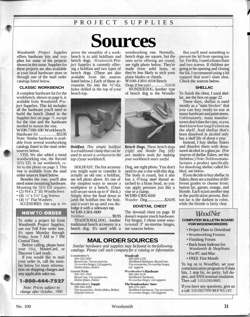
HOLDFAST. The first accessoryyou might want to consider isactually an old one: a holdfast,see left photo above. It's one ofthe simplest ways to secure aworkpiece to a bench. (Ourswill secure stock up to 4" thick.)Simply drive the head down tojamb the holdfast into the hole,and it won't let up until you dis-lodge it with a sideways tap.W100-1301-600Holdfast.............................. $9.95
TRADITIONAL DOG. Anothertraditional bench accessory is abench dog. It's used with a
Bench Dogs. These bench dogs(right) and Wonder Dog (left)are modern tools for makingyour workbench mare useful.
Dog, see right photo. You don'tneed to use a vise with this dog.The body is round, but it alsohas a 6"-long steel thread at-tached to a brass head, so youcan apply pressure just like avise or a clamp.W100-1301-616Wonder Dog.....................$24.95
DOVETAIL CHESTThe dovetail chest on page 18doesn't require much hardware.For hinges, I chose some easy-to-install 3" no-mortise hinges,see sources below.
MAIL ORDER SOURCESSimilar hardware and supplies may be found in the following
catalogs. Please call each company for a catalog or information.Constantine's
800-223-8087Record vise, Vise accessories,Mi-mortise hinges, Lid supports,
Woodcraft800-225-1153Workbench hardware, Record vise,
GarrettWade800-221-2942
Shellac flakes, BehkolWoodworker's Supply800-645-9292Vise accessories, Shettac flakes, Behkol,Drywatt anchors
Lid supportsWoodworker's Hardware
800-383-0130Workbench hardware,No^marttse hinges, Lid supports
The Woodworkers' Store800-279-4441Workbench hardware, Vise accessories,No-mortise hinges, Lid Supports
But you'll need something toprevent the lid from opening toofar. For this, I used a brass chainand two screws. If children aregoing to be opening and closingthe lid, I recommend using a lidsupport that won't slam shut.Check the sources below.
SHELLACTo finish the chest, I used shel-lac, see the box on page 22.
These days, shellac is usedmostly as a "stain blocker" thatyou can buy ready-to-use atmany hardware and paint stores.Unfortunately, many manufac-turers don't date the cans, so youdon't know how long it's been onthe shelf. And shellac that'sbeen dissolved in alcohol onlyhas a shelf life of about a year.
Instead, I buy shellac flakesand dissolve them with dena-tured alcohol in a glass jar. (Forsources of shellac flakes, see thelist below.) Note: Behlens manu-factures a product specificallyfor dissolving shellac called Be-hkol, see below.
If you decide to buy shellac inflakes, there are a number of dif-ferent grades to choose from:button lac, garnet, orange, andblonde. Each is just another stepin the purification process. But-ton lac is the darkest in color,while the blonde is fairly clear.
WvdNetCOMPUTER BULLETIN BOARD
FOR WOODWORKERS• Project Plans to Download• Woodworking Forums• Finishing Forum• Back Issue Indexes for
Woodsmith & ShopNotes• For PC and Mac• FREE First Month
To log on to WoodNet, set yourcommunication program to 8 databits, 1 stop bit, no parity, full du-plex, and ANSI terminal emulation.Then call 1-515-245-9663.If you have any questions, give usa call: 515-282-7000 M-F 9-5 CST
No. 100 Woodsmith 31

A L A S T L O O K
Final Details
Hand-CutDovetails Page 24Cutting dovetails by hand isn'tjust for the experts. You can createa tight-fitting joint with our step-by-step instructions.
Dovetail Chest Page 18With its clean lines and hand-cutdovetails, this pine chest will fitalmost any room in your home.
Classic Workbench Page 6Not only does this bench feature asolid, laminated top, it also hasan enclosed base to store a varietyof tools and accessories.
32 Woodsmith No. 100


