Page 1
www.makerfabs.com [email protected]
Maduino GPRS A6 v1.5 user manual
Version: 0.9
Editor: Sam
Maduino GPRS A6 is a one-stop solution for IOT (Internet of Things) projects, it integrate
a micro Controller Atmega 328, GRRS/GSM module A6, on-board power management
and storage, to make the Maduino GPRS A6 ready for real project for IOT projects such
as smart-home, outdoor monitoring, shared bicycle, etc. The GRPS/GSM module A6
support quad-band 850/900/1800/1900MHz, that covers any GSM network, after inserting
a SIM card, then you will able to use the SMS/GPRS service of Cellular connectivity.
The Maduino GPRS A6 based on the Arduino, users can program it with Arduino IDE,
which is very easy especially suit for the none-programmers. There are also detailed
guide for users to learn how to create the first IOT project with Maduino GPRS A6 board,
with which the starters can learn the hardware and programming skill quickly.
Features:
Powered by lithium battery 3.4-4.2V or USB
ATmega328: 8MHz, 32KB flash, 2KB SRAM
Integrated Power Control System
Quad-band: 850/900/1800/1900Mz
Interface: I2C/SPI/UART/18*GPIO
Arduino Compatible
Working Temperature: -20 – 85℃
Default baud rate: 115200
Size: 40*55mm
Page 2
www.makerfabs.com [email protected]
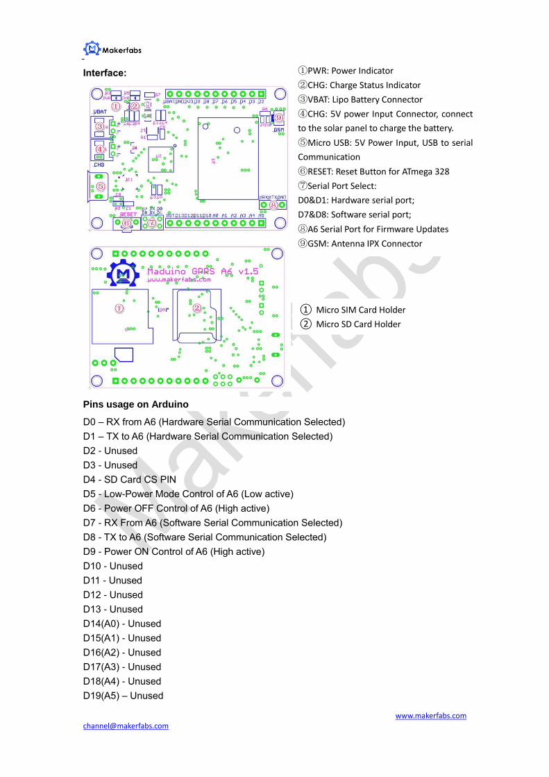
Interface:
Pins usage on Arduino
D0 – RX from A6 (Hardware Serial Communication Selected)
D1 – TX to A6 (Hardware Serial Communication Selected)
D2 - Unused
D3 - Unused
D4 - SD Card CS PIN
D5 - Low-Power Mode Control of A6 (Low active)
D6 - Power OFF Control of A6 (High active)
D7 - RX From A6 (Software Serial Communication Selected)
D8 - TX to A6 (Software Serial Communication Selected)
D9 - Power ON Control of A6 (High active)
D10 - Unused
D11 - Unused
D12 - Unused
D13 - Unused
D14(A0) - Unused
D15(A1) - Unused
D16(A2) - Unused
D17(A3) - Unused
D18(A4) - Unused
D19(A5) – Unused
①PWR: Power Indicator
②CHG: Charge Status Indicator
③VBAT: Lipo Battery Connector
④CHG: 5V power Input Connector, connect
to the solar panel to charge the battery.
⑤Micro USB: 5V Power Input, USB to serial
Communication
⑥RESET: Reset Button for ATmega 328
⑦Serial Port Select:
D0&D1: Hardware serial port;
D7&D8: Software serial port;
⑧A6 Serial Port for Firmware Updates
⑨GSM: Antenna IPX Connector
① Micro SIM Card Holder
② Micro SD Card Holder
Page 3
www.makerfabs.com [email protected]
Application
[Case one]: GSM Connectivity
With the Maduino GPRS A6, users can create IOT projects such as remote controlling.
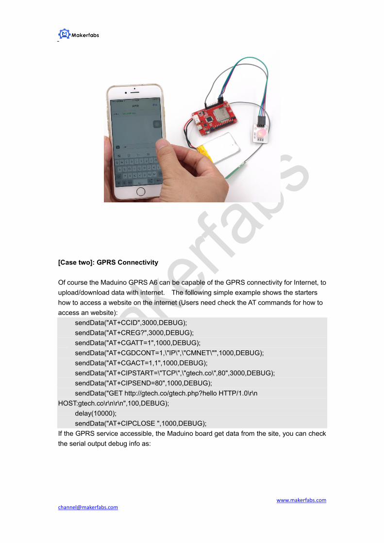
The following simple application is using the SMS to control a RGB LED, it would be
convenient for remote controlling without any internet, only with the 2G GSM connectivity
that you can control hardware remotely.
1. Insert a Micro SIM card
The Maduino GPRS A6 board uses the micro SIM card that is widely used in Android
phone, install the Micro SIM card to the holder as below picture.
Note that some fee maybe needed for each SMS depends on your local GSM Operator,
make sure that the SIM Card is active and enough money left for this application.
2. Connect the GSM Antenna and the 3.7V battery
3. Connect the module that you want to control by Maduino A6.
Connect an RGB LED module to the Maduino GPRS A6 as the following connection:
RGB LED Module----- Maduino GPRS A6
V-----Vbat
R------D2
G-----D3
B-----D4
Page 4
www.makerfabs.com [email protected]
Actually you can connect plenty of other modules that can be controlled by the simple
On/Off Commands. For Example, a Relay can be connected, to control the AC110V or
220V connectivity, and a DC motor can be connected and controlled, to created Automatic
agriculture applications.
4. Programming and Download
The Codes for this application is simple, firstly, define the control pins: (Demo Code
Download)
//define the RGB LED connection to the Maduino GRPS A6:
int LED_R = 2;
int LED_G = 3;
int LED_B= 4;
When some characters are received, turn on/off the related LED color :
SerialInByte = (unsigned char)mySerial.read();
if( SerialInByte == 13 )// if some charactors are received from the A6;
{
ProcessGprsMsg();
}
Turn On/Off t the LED, depends on the charactor received: ( Note that the RGB LED is
Low active)
void ProcessSms( String sms )
{
Serial.print( "ProcessSms for [" );
Serial.print( sms );
Serial.println( "]" );
if( sms.indexOf("onr") >= 0 ){ //If “onr“ receoved
digitalWrite(LED_R, LOW); // Turn On the Red Color
Serial.println( "LED Red ON" );
}
Page 5
www.makerfabs.com [email protected]
if( sms.indexOf("ong") >= 0 ){
digitalWrite( LED_G, LOW);// Turn Off the Green Color
Serial.println( "LED Green ON" );
}
if( sms.indexOf("onb") >= 0 ){
digitalWrite(LED_B, LOW);
Serial.println( "LED Blue ON" );//Turn On the Blue Color
}
if( sms.indexOf("offr") >= 0 ){
digitalWrite( LED_R,HIGH);//Turn Off the Red Color
Serial.println( "LED Red OFF" );
}
if( sms.indexOf("offg") >= 0 ){
digitalWrite(LED_G, HIGH ); //Turn Off the Green Color
Serial.println( "LED Green OFF" );
}
if( sms.indexOf("offb") >= 0 ){
digitalWrite(LED_B, HIGH ); //Turn Off the Blue Color
Serial.println( "LED Blue OFF" );
}
}
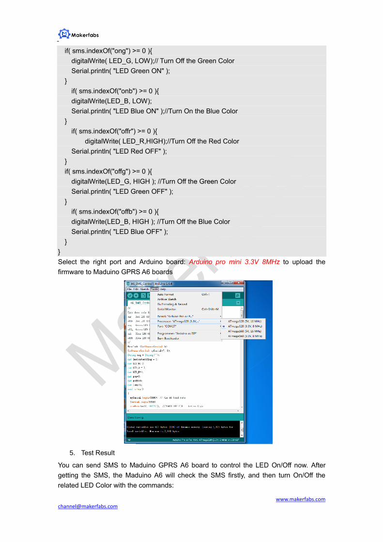
Select the right port and Arduino board: Arduino pro mini 3.3V 8MHz to upload the
firmware to Maduino GPRS A6 boards
5. Test Result
You can send SMS to Maduino GPRS A6 board to control the LED On/Off now. After
getting the SMS, the Maduino A6 will check the SMS firstly, and then turn On/Off the
related LED Color with the commands:
Page 6
www.makerfabs.com [email protected]
[Case two]: GPRS Connectivity
Of course the Maduino GPRS A6 can be capable of the GPRS connectivity for Internet, to
upload/download data with internet. The following simple example shows the starters
how to access a website on the internet (Users need check the AT commands for how to
access an website):
sendData("AT+CCID",3000,DEBUG);
sendData("AT+CREG?",3000,DEBUG);
sendData("AT+CGATT=1",1000,DEBUG);
sendData("AT+CGDCONT=1,\"IP\",\"CMNET\"",1000,DEBUG);
sendData("AT+CGACT=1,1",1000,DEBUG);
sendData("AT+CIPSTART=\"TCP\",\"gtech.co\",80",3000,DEBUG);
sendData("AT+CIPSEND=80",1000,DEBUG);
sendData("GET http://gtech.co/gtech.php?hello HTTP/1.0\r\n
HOST:gtech.co\r\n\r\n",100,DEBUG);
delay(10000);
sendData("AT+CIPCLOSE ",1000,DEBUG);
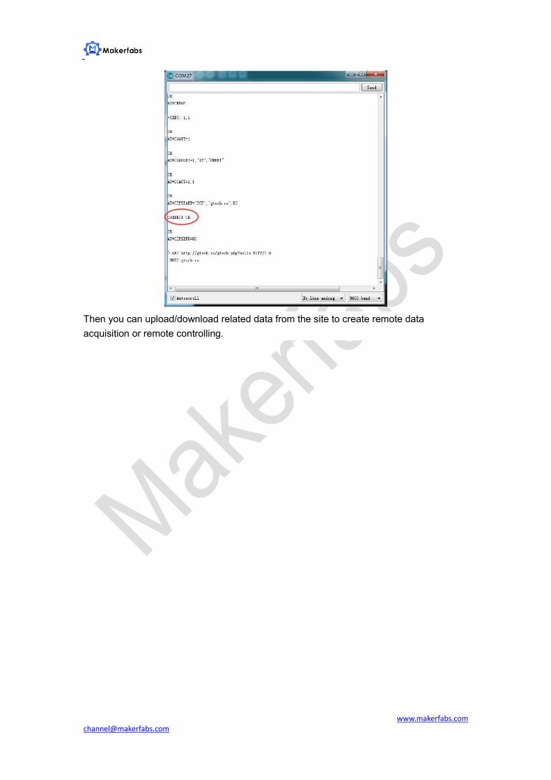
If the GPRS service accessible, the Maduino board get data from the site, you can check
the serial output debug info as:
Page 7
www.makerfabs.com [email protected]
Then you can upload/download related data from the site to create remote data
acquisition or remote controlling.