28
MAE 322 Machine Design Shafts -3 Dr. Hodge Jenkins Mercer University
| Date post: | 22-Apr-2018 |
| Category: |
Documents |
| Upload: | nguyenthuan |
| View: | 227 times |
| Download: | 8 times |
MAE 322
Machine Design
Shafts -3 Dr. Hodge Jenkins
Mercer University
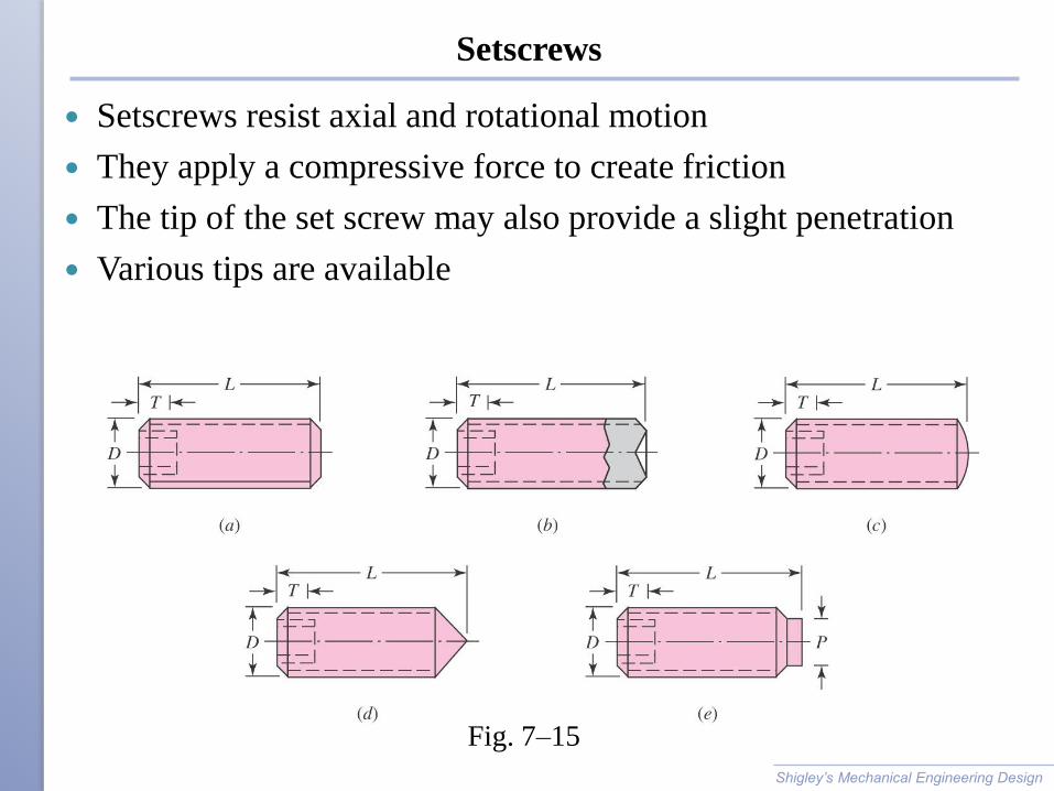
Setscrews
Setscrews resist axial and rotational motion
They apply a compressive force to create friction
The tip of the set screw may also provide a slight penetration
Various tips are available
Shigley’s Mechanical Engineering Design
Fig. 7–15
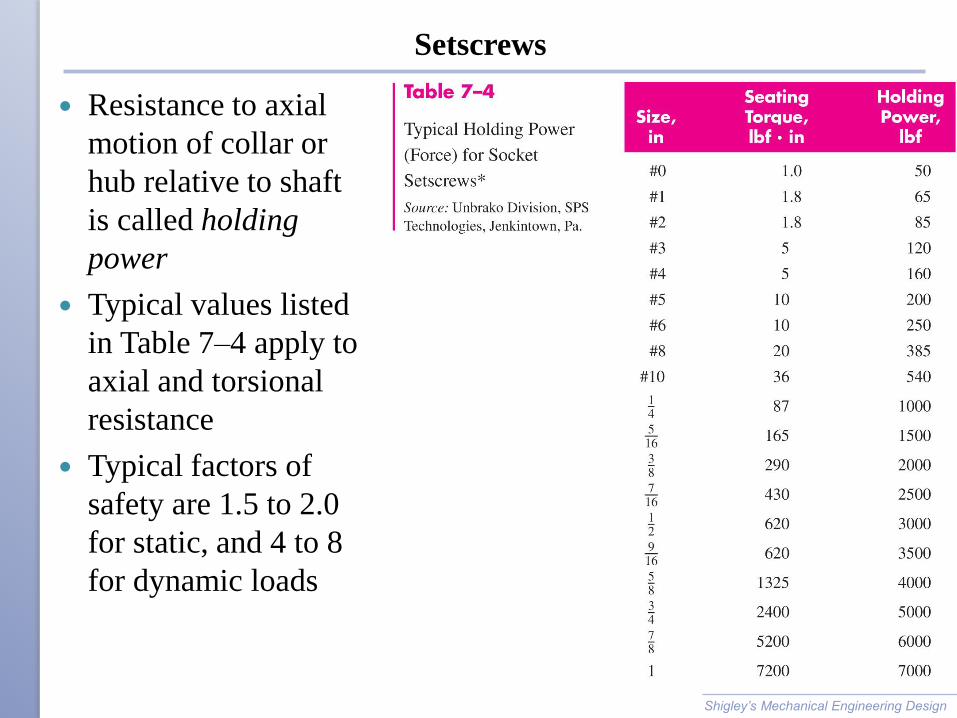
Setscrews
Resistance to axial
motion of collar or
hub relative to shaft
is called holding
power
Typical values listed
in Table 7–4 apply to
axial and torsional
resistance
Typical factors of
safety are 1.5 to 2.0
for static, and 4 to 8
for dynamic loads
Shigley’s Mechanical Engineering Design
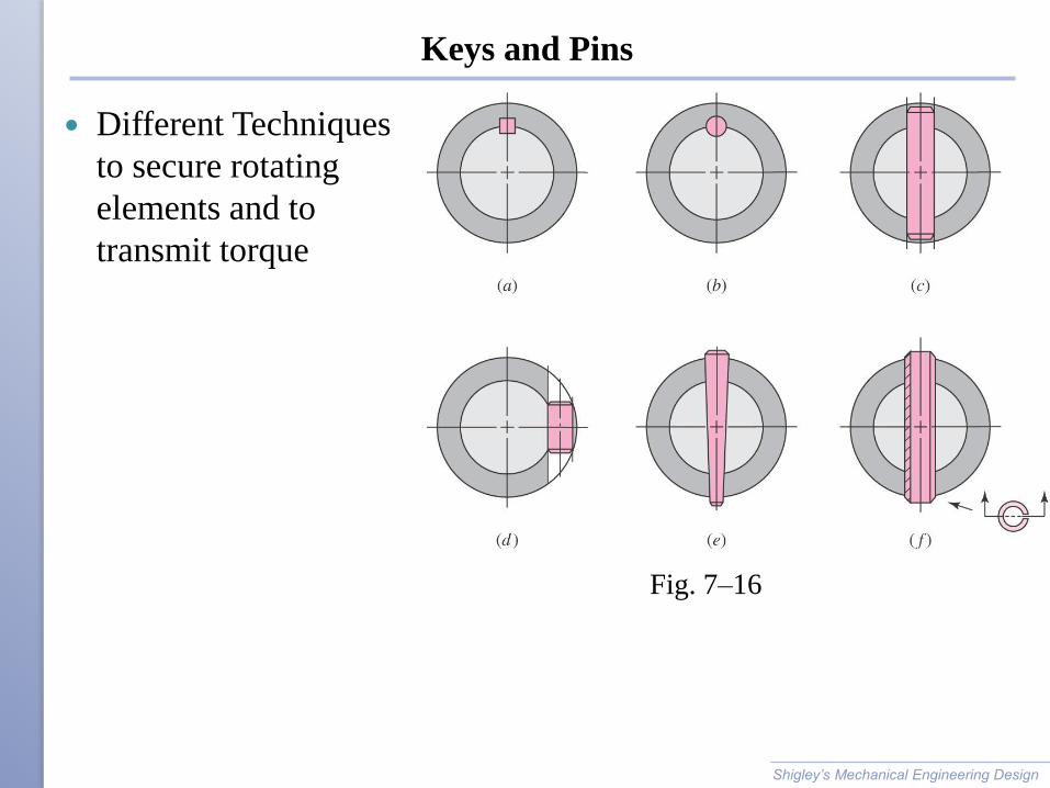
Keys and Pins
Different Techniques
to secure rotating
elements and to
transmit torque
Shigley’s Mechanical Engineering Design
Fig. 7–16

Standard Keys, Rectangular & Square
Shaft diameter
determines key
size
Shigley’s Mechanical Engineering Design
Table 7–6
Keys
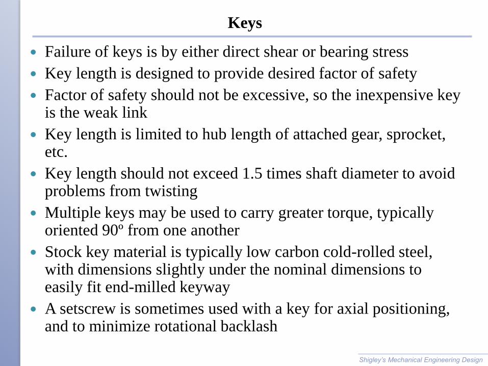
Failure of keys is by either direct shear or bearing stress
Key length is designed to provide desired factor of safety
Factor of safety should not be excessive, so the inexpensive key is the weak link
Key length is limited to hub length of attached gear, sprocket, etc.
Key length should not exceed 1.5 times shaft diameter to avoid problems from twisting
Multiple keys may be used to carry greater torque, typically oriented 90º from one another
Stock key material is typically low carbon cold-rolled steel, with dimensions slightly under the nominal dimensions to easily fit end-milled keyway
A setscrew is sometimes used with a key for axial positioning, and to minimize rotational backlash
Shigley’s Mechanical Engineering Design

Gib-head Key
Gib-head key is tapered so that when firmly driven it prevents
axial motion
Head makes removal easy
Projection of head may be hazardous
Shigley’s Mechanical Engineering Design
Fig. 7–17
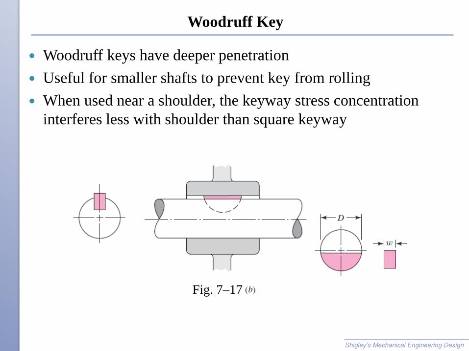
Woodruff Key
Woodruff keys have deeper penetration
Useful for smaller shafts to prevent key from rolling
When used near a shoulder, the keyway stress concentration
interferes less with shoulder than square keyway
Shigley’s Mechanical Engineering Design
Fig. 7–17

Standard Woodruff Keys
Shi
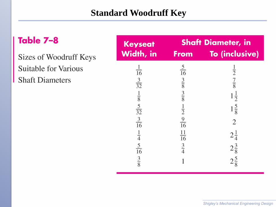
Standard Woodruff Key
Shigley’s Mechanical Engineering Design
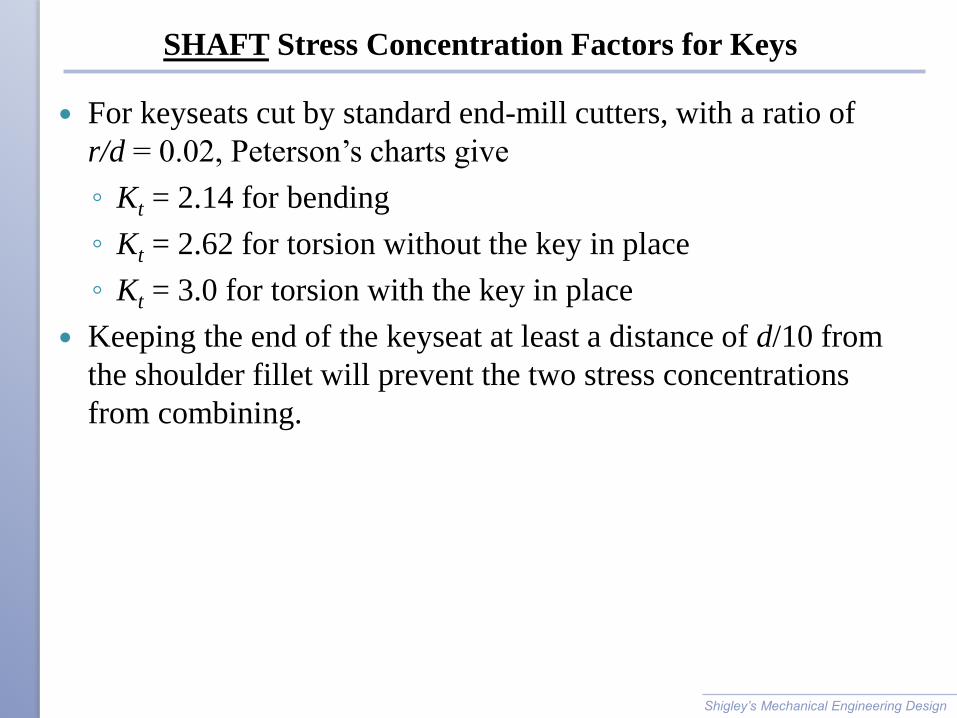
SHAFT Stress Concentration Factors for Keys
For keyseats cut by standard end-mill cutters, with a ratio of
r/d = 0.02, Peterson’s charts give
◦ Kt = 2.14 for bending
◦ Kt = 2.62 for torsion without the key in place
◦ Kt = 3.0 for torsion with the key in place
Keeping the end of the keyseat at least a distance of d/10 from
the shoulder fillet will prevent the two stress concentrations
from combining.
Shigley’s Mechanical Engineering Design
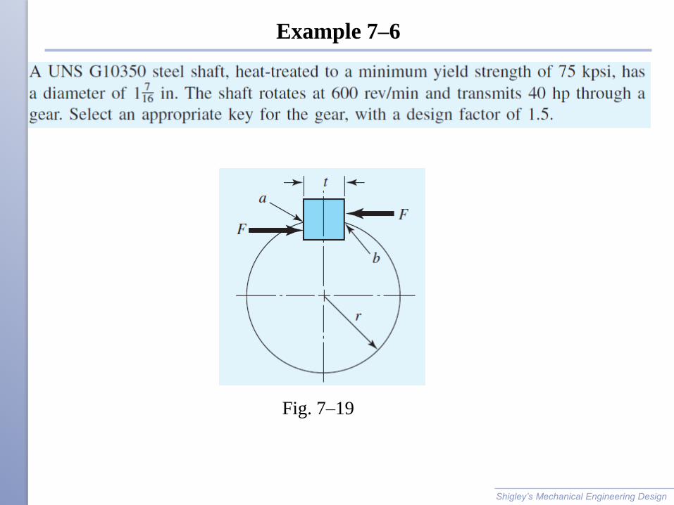
Example 7–6
Shigley’s Mechanical Engineering Design
Fig. 7–19

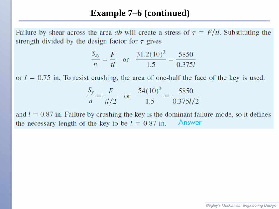
Example 7–6 (continued)
Shigley’s Mechanical Engineering Design
Example 7–6 (continued)
Shigley’s Mechanical Engineering Design

Retaining Rings
Retaining rings are often used instead of a shoulder to provide
axial positioning
Shigley’s Mechanical Engineering Design
Fig. 7–18

Nomenclature for Cylindrical Fit
Upper case letters
refer to hole
Lower case letters
refer to shaft
Basic size is the
nominal diameter and
is same for both parts,
D=d
Tolerance is the
difference between
maximum and
minimum size
Deviation is the
difference between a
size and the basic size Shigley’s Mechanical Engineering Design
Fig. 7–20

Tolerance Grade Number
Tolerance is the difference between maximum and minimum size
International tolerance grade numbers designate groups of
tolerances such that the tolerances for a particular IT number
have the same relative level of accuracy but vary depending on
the basic size
Shigley’s Mechanical Engineering Design

Tolerance Grades – Inch Series
Shigley’s Mechanical Engineering Design
Table A–13

Description of Preferred Fits (Clearance)
Shigley’s Mechanical Engineering Design
Table 7–9
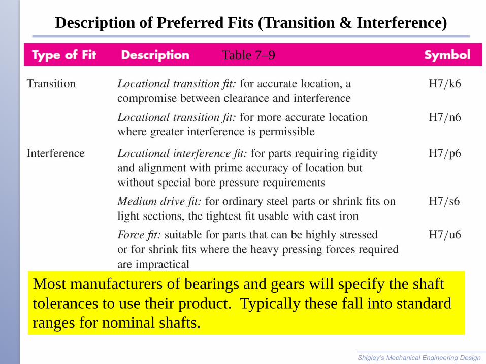
Description of Preferred Fits (Transition & Interference)
Shigley’s Mechanical Engineering Design
Table 7–9
Most manufacturers of bearings and gears will specify the shaft
tolerances to use their product. Typically these fall into standard
ranges for nominal shafts.
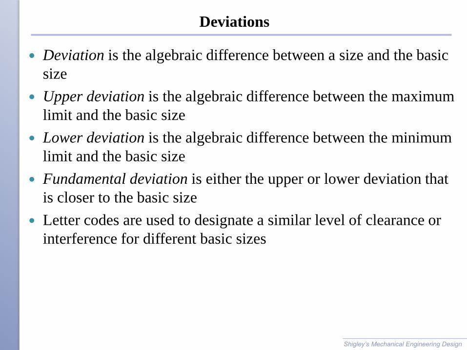
Deviations
Deviation is the algebraic difference between a size and the basic
size
Upper deviation is the algebraic difference between the maximum
limit and the basic size
Lower deviation is the algebraic difference between the minimum
limit and the basic size
Fundamental deviation is either the upper or lower deviation that
is closer to the basic size
Letter codes are used to designate a similar level of clearance or
interference for different basic sizes
Shigley’s Mechanical Engineering Design
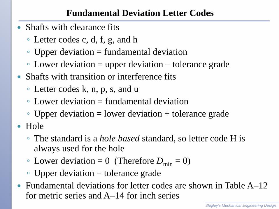
Fundamental Deviation Letter Codes
Shafts with clearance fits
◦ Letter codes c, d, f, g, and h
◦ Upper deviation = fundamental deviation
◦ Lower deviation = upper deviation – tolerance grade
Shafts with transition or interference fits
◦ Letter codes k, n, p, s, and u
◦ Lower deviation = fundamental deviation
◦ Upper deviation = lower deviation + tolerance grade
Hole
◦ The standard is a hole based standard, so letter code H is always used for the hole
◦ Lower deviation = 0 (Therefore Dmin = 0)
◦ Upper deviation = tolerance grade
Fundamental deviations for letter codes are shown in Table A–12 for metric series and A–14 for inch series
Shigley’s Mechanical Engineering Design

Fundamental Deviations – Inch series
Shigley’s Mechanical Engineering Design
Table A–14

Procedure to Size for Specified Fit
Select description of desired fit from Table 7–9.
Obtain letter codes and IT grades from symbol for desired fit
from Table 7–9
Use Table A–11 (metric) or A–13 (inch) with IT grade numbers
to obtain DD for hole and Dd for shaft
Use Table A–12 (metric) or A–14 (inch) with shaft letter code to
obtain dF for shaft
For hole
For shafts with clearance fits c, d, f, g, and h
For shafts with interference fits k, n, p, s, and u
Shigley’s Mechanical Engineering Design
Stress in Interference Fits
Interference fit generates pressure at interface
Need to ensure stresses are acceptable
Treat shaft as cylinder with uniform external pressure
Treat hub as hollow cylinder with uniform internal pressure
Shigley’s Mechanical Engineering Design
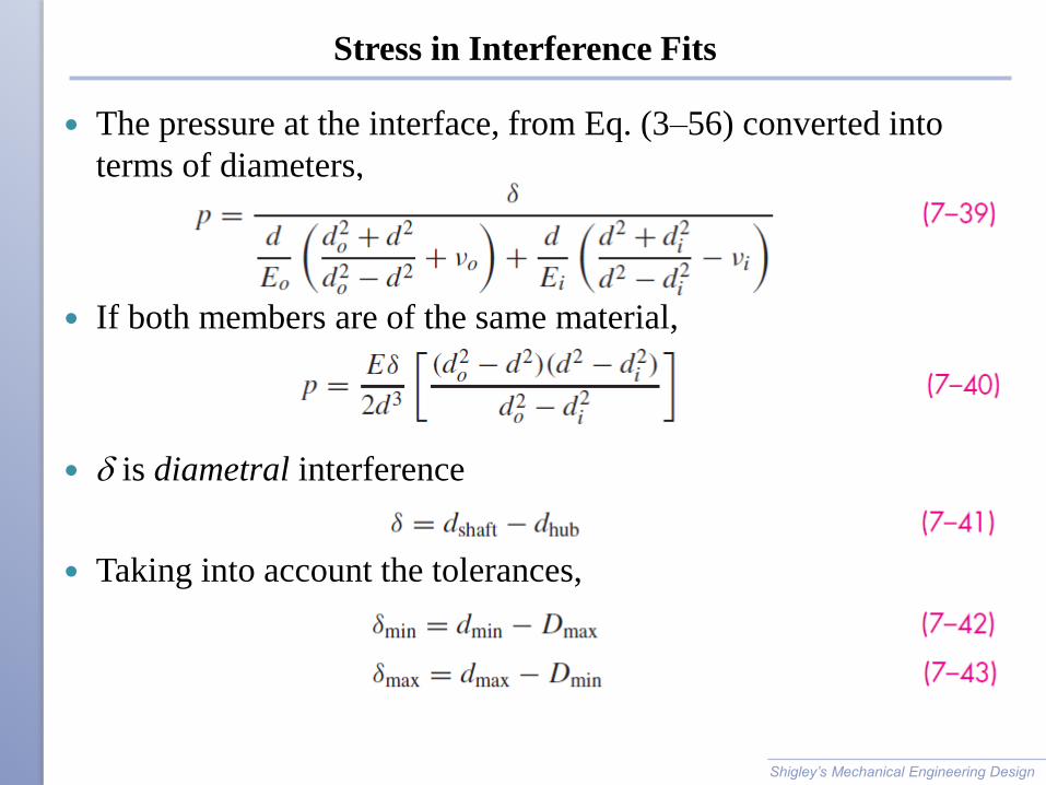
Stress in Interference Fits
The pressure at the interface, from Eq. (3–56) converted into
terms of diameters,
If both members are of the same material,
d is diametral interference
Taking into account the tolerances,
Shigley’s Mechanical Engineering Design
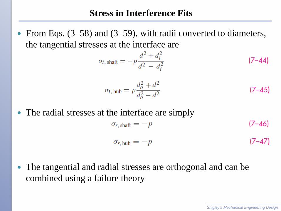
Stress in Interference Fits
From Eqs. (3–58) and (3–59), with radii converted to diameters,
the tangential stresses at the interface are
The radial stresses at the interface are simply
The tangential and radial stresses are orthogonal and can be
combined using a failure theory
Shigley’s Mechanical Engineering Design
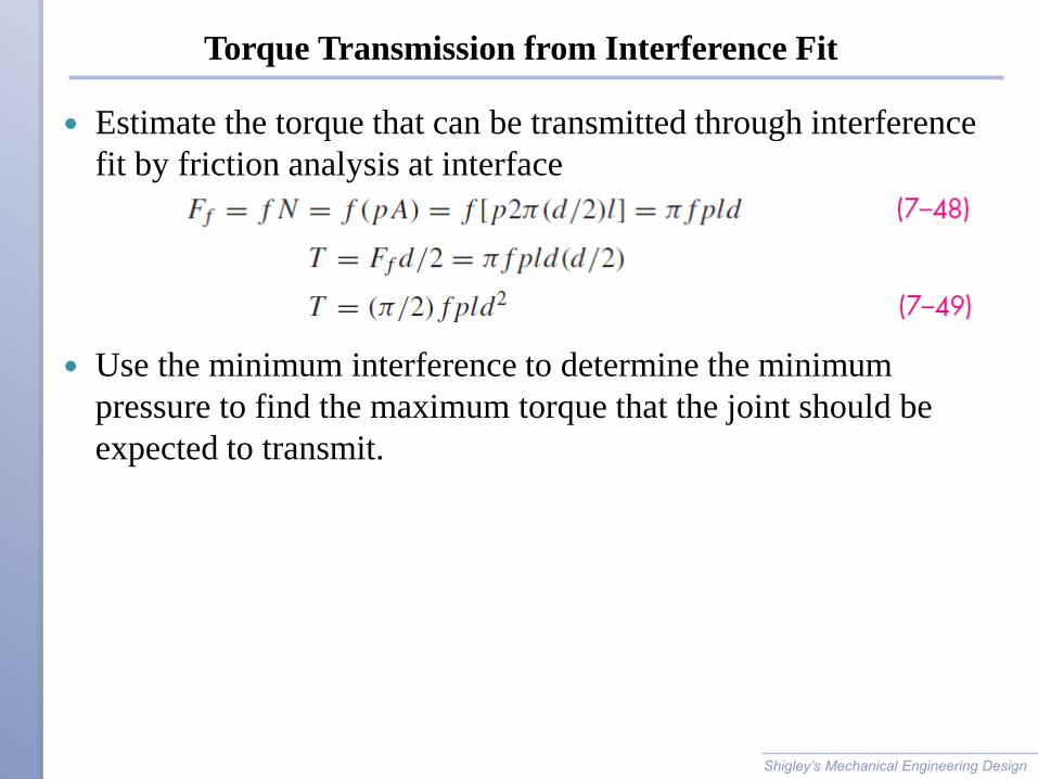
Torque Transmission from Interference Fit
Estimate the torque that can be transmitted through interference
fit by friction analysis at interface
Use the minimum interference to determine the minimum
pressure to find the maximum torque that the joint should be
expected to transmit.
Shigley’s Mechanical Engineering Design


