MAE 559 Fall 2009 Final Project: Ballpoint pen Paul Reverdy 8 January 2010 1 Introduction The ballpoint pen is one of the most simple, ubiquitous devices whose function depends on surface tension. The history of its invention is complicated: during several decades many inventors tried to improve on the fountain pen without much practical success. In the years leading up to World War 2 the B´ ır´ o brothers from Hungary developed the general design that has become standard. 1 Several years after the war Michel Bich developed a cheaper, mass market version of the B´ ır´ o design and the Bic Crystal pen was born. Modern ballpoint pens are much improved compared to fountain pens, but still do not always perform as desired. As anyone who has spent enough time writing will recognize, the pens will occasionally skip or smudge. In general, there are conditions under which the pen will not lay down a consistent layer of ink. In the same spirit as studies of the printer’s instability, I intend to study the quantitative conditions under which ballpoint pens fail to perform as desired. This analysis would be useful for designing better pens, and as we will see below is related to a variety of other interesting problems. 1 This is why in British English ballpoint pens are often referred to as Biros. 1
Transcript
MAE 559
Fall 2009
Final Project: Ballpoint pen
Paul Reverdy
8 January 2010
1 Introduction
The ballpoint pen is one of the most simple, ubiquitous devices whose function depends on
surface tension. The history of its invention is complicated: during several decades many
inventors tried to improve on the fountain pen without much practical success. In the years
leading up to World War 2 the Bıro brothers from Hungary developed the general design
that has become standard.1 Several years after the war Michel Bich developed a cheaper,
mass market version of the Bıro design and the Bic Crystal pen was born.
Modern ballpoint pens are much improved compared to fountain pens, but still do not
always perform as desired. As anyone who has spent enough time writing will recognize,
the pens will occasionally skip or smudge. In general, there are conditions under which the
pen will not lay down a consistent layer of ink. In the same spirit as studies of the printer’s
instability, I intend to study the quantitative conditions under which ballpoint pens fail to
perform as desired. This analysis would be useful for designing better pens, and as we will
see below is related to a variety of other interesting problems.1This is why in British English ballpoint pens are often referred to as Biros.
1
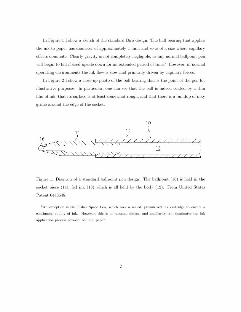
In Figure 1 I show a sketch of the standard Bıro design. The ball bearing that applies
the ink to paper has diameter of approximately 1 mm, and so is of a size where capillary
effects dominate. Clearly gravity is not completely negligible, as any normal ballpoint pen
will begin to fail if used upside down for an extended period of time.2 However, in normal
operating environments the ink flow is slow and primarily driven by capillary forces.
In Figure 2 I show a close-up photo of the ball bearing that is the point of the pen for
illustrative purposes. In particular, one can see that the ball is indeed coated by a thin
film of ink, that its surface is at least somewhat rough, and that there is a buildup of inky
grime around the edge of the socket.
Figure 1: Diagram of a standard ballpoint pen design. The ballpoint (16) is held in the
socket piece (14), fed ink (13) which is all held by the body (12). From United States
Patent 6443648.
2An exception is the Fisher Space Pen, which uses a sealed, pressurized ink cartridge to ensure a
continuous supply of ink. However, this is an unusual design, and capillarity still dominates the ink
application process between ball and paper.
2
Figure 2: A close-up photo of the ball bearing at the heart of a ballpoint pen. Note the
thin film of ink on the ball and the amount of buildup around the edge of the socket. From
Wikimedia Commons.
3
2 Questions
Based on the above observations, we can break down the functioning of the pen into a
variety of smaller problems for analysis.
2.1 Lubricated ball rotating in a socket
The point of the pen is essentially a lubricated ball bearing. It is driven by friction between
itself and the paper or other writing surface. Thus, one potential mode of failure for the
pen is for the ball to become jammed in the socket or stop spinning because of a lack of
friction between the ball and the paper. This last hypothesis is supported by the difficulty
of writing on slick surfaces, such as wax-coated paper, glass or many plastics.
There is a literature on lubrication theory in ball bearings which is relevant here. The
two papers by Savage [5],[6] are a good beginning. There are a number of qualitative
questions that one can ask, such as whether or not such lubrication films are stable. More
quantitative questions include whether there is a critical speed above which the film is
unstable, or whether the ball will tend to jam depending on the amount of pressure with
which the pen is put to paper.
2.2 Ink film on a ball
As my group showed in the project for Homework 3, a thin film on a sphere is unstable
even in the absence of gravity. In the presence of gravity, one would expect the film to be
even more unstable.
Purely considering the instability of the film when the pen is out of use, this could
cause failure in at least two ways: first, if the film goes unstable and ruptures in some
places, the lack of ink could cause the pen to skip on beginning writing. Second, the
instability will cause the film to thicken and pool in some some locations, which could then
either be deposited directly on the paper or pushed towards the edge of the socket. This
4
second hypothesis provides a potential explanation for the grime seen around the edge of
the socket in the photo.
A relevant quantitative question here is to determine the time scale on which the
instability tends to develop, to see, for example, whether it could develop quickly enough
to be relevant during writing.
2.3 Transfer of ink from ball to paper
In his study of the printer’s instability, Pearsons [4] has shown that, for a thin film contained
by slowly diverging boundaries, there is always a critical speed above which the film is
unstable. Though his work was for the quasi one-dimensional case, it is reasonable to
assume that a similar instability would exist for the ballpoint pen.
In the setup of the classical printer’s instability problem the roller has some rotational
speed that is externally imposed. This is opposed to our case where the ball is rolling due to
friction with the paper at a speed determined internally by the parameters of the problem.
However, if we ignore the details of how the speed of the ball’s rotation is determined a
classical printer’s instability calculation in this spherical geometry is relevant.
The two papers by Savage [5],[6] are again a good beginning, along with the one by
Pearsons. The paper by Hakim et al. [2] is a good reference for this particular printer’s
instability calculation.
2.4 Imbibition problem for ink
Once the ink is on the paper there is the question of whether it can imbibe the paper
or whether it will sit on the surface. If it does imbibe the paper, how quickly can it do
so? Slowly imbibing ink would be more likely to get smudged and so is something to be
avoided, while one would also want to avoid the ink bleeding through the paper. This is
more an issue of surface and ink chemistry so I will not treat it farther beyond saying that
ink formulation is important and this aspect should not be forgotten when trying to devise
5
new products based on the results of the other analysis.
2.5 Is the ink Newtonian?
One of the few companies to provide any details about the composition of their ballpoint
pen inks is the Fisher Space Pen company, which describes the ink they use in their space
pens as “thixotropic ink-semisolid until the shearing action of the rolling ball [liquefies]
it.” Clearly such ink is non-Newtonian as its viscosity decreases over time under constant
shear. Such ink would be stabilizing for the thin film on a sphere instability and would
likely also help avoid other issues.
A quick search of the patent literature suggests that inks are often designed to be
non-Newtonian. Gel inks in particular appear to have complex rheology. However, it is
difficult to know the characteristics of the various inks used by other manufacturers without
specifically testing them, as the companies do not generally reveal detailed information.
As a first pass at analysis I will assume that the inks are Newtonian fluids.
3 Dimensional parameters
To frame the discussion that follows, I will take note of the various dimensional quantities
that are relevant to the problem.
• R, Radius of ball: ≈ 1 mm.
• Vmax, Maximum speed of the pen tip when writing: on the order of 10 cm/s, maybe
up to about 50 cm/s.
• σ, Surface tension of the ink-air interface: Depends on the specific ink, but on the
order of the value for the water-air interface, 70 mN/m.
• ρ, Density of the ink: again, on the order of the value for water, 1000 kg/m3.
6
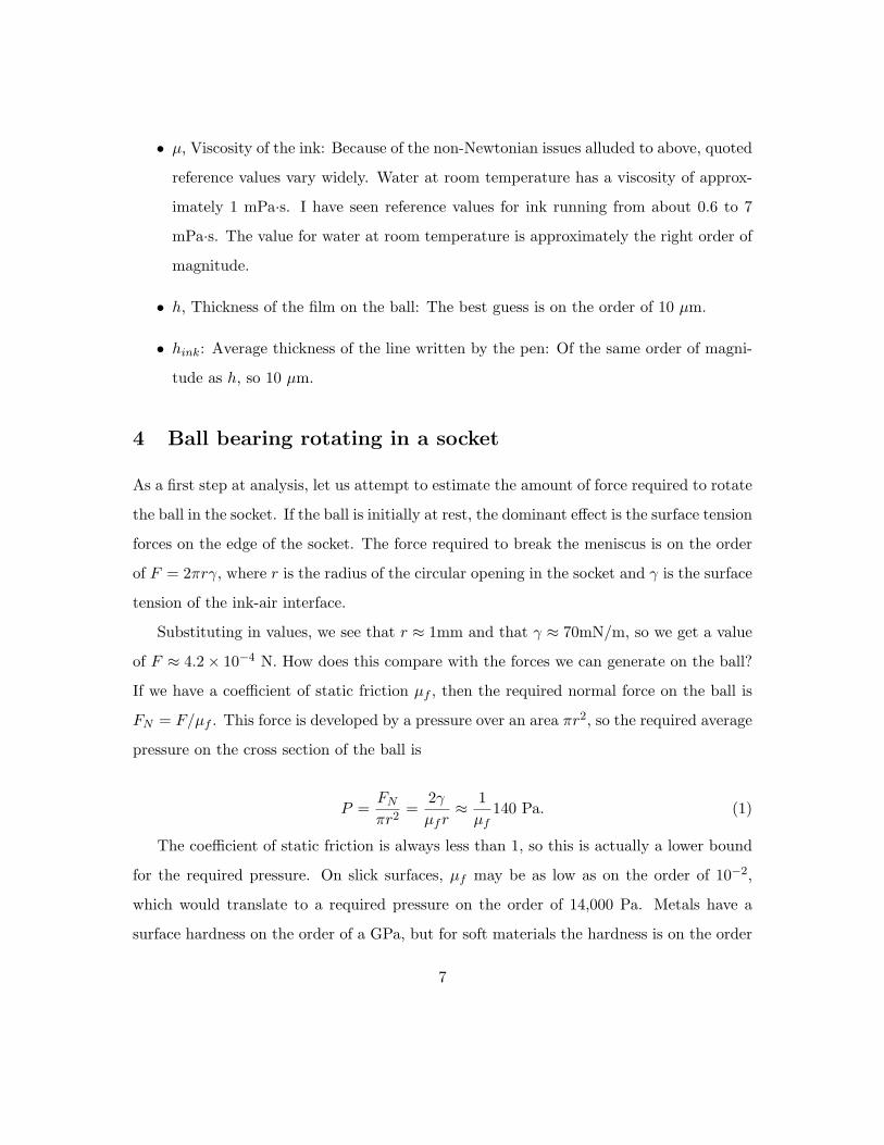
• µ, Viscosity of the ink: Because of the non-Newtonian issues alluded to above, quoted
reference values vary widely. Water at room temperature has a viscosity of approx-
imately 1 mPa·s. I have seen reference values for ink running from about 0.6 to 7
mPa·s. The value for water at room temperature is approximately the right order of
magnitude.
• h, Thickness of the film on the ball: The best guess is on the order of 10 µm.
• hink: Average thickness of the line written by the pen: Of the same order of magni-
tude as h, so 10 µm.
4 Ball bearing rotating in a socket
As a first step at analysis, let us attempt to estimate the amount of force required to rotate
the ball in the socket. If the ball is initially at rest, the dominant effect is the surface tension
forces on the edge of the socket. The force required to break the meniscus is on the order
of F = 2πrγ, where r is the radius of the circular opening in the socket and γ is the surface
tension of the ink-air interface.
Substituting in values, we see that r ≈ 1mm and that γ ≈ 70mN/m, so we get a value
of F ≈ 4.2× 10⁻⁴ N. How does this compare with the forces we can generate on the ball?
If we have a coefficient of static friction µf , then the required normal force on the ball is
FN = F/µf . This force is developed by a pressure over an area πr2, so the required average
pressure on the cross section of the ball is
P =FNπr2
=2γµfr≈ 1µf
140 Pa. (1)
The coefficient of static friction is always less than 1, so this is actually a lower bound
for the required pressure. On slick surfaces, µf may be as low as on the order of 10−2,
which would translate to a required pressure on the order of 14,000 Pa. Metals have a
surface hardness on the order of a GPa, but for soft materials the hardness is on the order
7
of 105 Pa, so this is a plausible explanation for the pen to fail to begin to write on slick
and soft materials.
5 Film thicknesses
In the following, it becomes important to know the thickness of the ink film on the ball and
the thickness of the film deposited on the paper. In the Landau-Levich class of problems the
thin film deposited is “self-metered”, so that the thickness is determined by the parameters
of the problem.
These calculations are generally restricted to small capillary numbers, which depending
on how we define our capillary number could exclude a large portion of the pen operating
regime. If our capillary number is defined as Ca = V0µ/σ, then using our reference param-
eters for µ, σ and Vmax we have Camax = 0.5/70 ≈ 0.007, and we are always in the limit
of small capillary numbers.
However, in some papers authors define a capillary number taking into account the
geometric factor R/h0, which is the ratio of the sphere radius to the film thickness. In the
following I have generally estimated h0 to be on the order of 10 µm, and we know that R
is on the order of 1 mm. In this case we have Camax ≈ 0.7 and the capillary number is no
longer particularly small.
Some experiment is required in order to understand how to choose between these two
scalings and find the film thicknesses.
6 Instability of a thin film on a sphere
Given a thin film of dimensionless thickness h0, we have shown that the dimensionless
linearized diffusion equation for a perturbation h in the film thickness is
sin(θ)∂h
∂t= −1
2
(h2
0 +43h3
0
)(∂
∂θ
(sin(θ)
∂P
∂θ
)+
∂
∂φ
(1
sin(θ)∂P
∂φ
)). (2)
8
We proceed using a perturbation of the form h(θ, φ, t) = εf(θ, φ)eσt, where the function
f(θ, φ) is a spherical harmonic Y lm. Substituting this perturbation into Equation 2 we find
that σ is positive for all the spherical harmonics, so that the perturbation is growing and
the film unstable.
A reasonable question to ask at this point is how quickly the instability will develop, so
we can determine whether or not the instability time scale is short enough to be relevant
to the other dynamics of the system. In our paper we find that σ is at least equal to 12A,
where A = h20 + 4
3h30, and h0 = h/R, which is the film thickness scaled by the sphere’s
radius.
Substituting in values of h and R, we find that A ≈ 10−4 so in dimensionless terms τ ,
the time scale for the development of the instability, is at the most on the order of 103.
Dimensionally, we have scaled time by the quantity µ/P0, which using our reference value
of viscosity and the ambient atmospheric pressure is equal to approximately 10−8s. Thus,
the time scale of the instability is at most on the order of 10−5s.
This time scale is incredibly fast, so our analysis seems improbable in this case. This
is probably related to the non-Newtonian character of the ink, which would be stabilizing
and therefore extend the time scale of the instability.
7 Printer’s instability for a roller on a plate
The standard analysis of the printer’s instability is in the symmetrical geometry where
there are two counterrotating cylinders. However, for the pen the geometry is asymmetric,
with a ball above the plane of the paper. As a first step, we can analyze the printer’s
instability in this asymmetric geometry; in essence studying the printer’s instability for a
one dimensional pen that transfers ink with a cylinder instead of a ball.
All this neglects that the ball is rolling due to friction with the paper, instead of
externally imposed.
9
7.1 Basic analysis
This problem is analyzed in several papers, but we will follow the calculation of Hakim et
al. [2]. The geometry is such that the x- and y-axes are in the plane of the plate, with the
y-axis aligned with the axis of the cylinder, and the z-axis pointing upwards. The cylinder
of radius R is placed above the plane such that the minimum distance between the cylinder
and the plane is b0, with the width of the gap being described by b(x).
The cylinder is driven at an externally imposed angular velocity Ω, so the linear velocity
of the edge of the cylinder is given by V0 = RΩ.
Because of the geometry of the system, we assume that we have a local Poiseuille-
Couette flow so that the fluid velocity u is assumed to be
u(x, z) = z
(V0
b(x)x +
z − b(x)2µ
~∇hP), (3)
where ~∇h denotes the two-dimensional horizontal gradient in x and y and P is the pres-
sure field. The symmetry along the y direction is reflected in the fluid velocity’s lack of
dependence on y.
The mean fluid velocity across the thin film is
u(x) =V0
2x− b2(x)
12µ~∇hP. (4)
The equation for the pressure field comes from the incompressibility of the oil
div(b(x)u(x)) = 0 =V0
2db(x)dx
− d
dx
(b3(x)12µ
)∂P
∂x− b3(x)
12µ
(∂2P
∂x2+∂2P
∂y2
). (5)
7.2 Dimensional analysis and finding the pressure field
For some reason the paper [2] leaves all the equations in dimensional form, but I will change
them to dimensionless form. Our dimensional parameters are the linear speed V0, the two
lengths R and b0 from the geometry of the problem and the fluid viscosity, surface tension
and density, respectively µ, σ and ρ.
10
I choose to scale lengths by b0 because I care more about the gap than imposed geometric
curvature, velocities by V0, and pressure by the group V0µ/b0. Then denoting dimensionless
quantities by a hat, the velocity field becomes
u(x, z) =z
b(x)x +
z − b(x)2
~∇hP (6)
and the mean velocity across the film becomes
u(x) =x2− b2(x)
12~∇hP . (7)
Now, we impose incompressibility and conservation of mass by saying that Q, the flux
of oil through the gap is constant, so we have Q = ux(x)b(x) = constant. By symmetry,
the pressure field varies only in the x direction, so we can quickly recover the equation for
the pressure field:dP
dx=
6
b2− 12
Q
b3. (8)
We can integrate this equation easily if we approximate b(x) by the osculating3 parabola
of the cylinder: b(x) ≈ x2
2R + b0, or in dimensionless terms,
b = 1 + βx2, (9)
where we have defined β ≡ b0/2R. This means we match the curvature of the boundary
at the point of minimum gap width. Furthermore, introduce the angle θ such that x =
β−1/2 tan θ, so that b = 1 + tan2 θ. Note that the boundary conditions x = ±∞ correspond
to the boundary conditions θ = ±θ/2.
Imposing the boundary condition that the pressure is equal to P0, the atmospheric
pressure, at θ = −π/2, the pressure field is given by
P (θ, Q)− P0 =3√β
(θ +
π
2+
12
sin 2θ)− 6Q√
β
(34
(θ +
π
2
)+
12
sin 2θ +116
sin 4θ). (10)
3Meaning the curve touching the boundary with the same tangent. From the Latin osculari, ‘to kiss’.
11
Finally, imposing that the pressure is again equal to the atmospheric pressure at θ =
π/2 closes the problem and implies that the flux is Q = 2/3. Substituting this into the
expression for the pressure field and simplifying shows that the pressure field is given by
P (x) = − 2√β
tan θ(1 + tan2 θ)
= −2x
b2. (11)
It is worth noting that Hakim et al. forget the factor of two in the above expression.
7.3 Analysis of the interface
At the meniscus, we have a Young-Laplace boundary condition for the pressure field:
P (xm) = P0 − σ(
2b(x)
+1ρ
), (12)
where 1/ρ is the curvature of the interface in the horizontal (xy) plane and 1/b(xm) is the
curvature in the vertical (yz) plane. We assume 1/ρ = 0 because of the symmetry in the
y direction, so the dimensionless boundary condition is
P (xm) = P0 −2Ca
1
b(xm), (13)
where Ca = V0µ/σ is the capillary number of the system.
Expressing conservation of fluid at the interface takes the form
Vnb(xm)(1− F (Ca)) = (n · u(rm)− F (Ca))b(xm), (14)
where Vn is the normal velocity of the interface at the point rm, n is the outward normal of
the meniscus, and the function F (Ca) is the constant of proportionality in the relationship
Q = αV0b(xm) which Landau and Levich [3] calculated through matching asymptotics.
For the form of F , we use the result that Hakim et al. use, which is
F (Ca) = 0.12(1− exp(−8.6Ca2/3)). (15)
12
7.4 Stability
Now, we do a linear stability analysis by introducing perturbations. The location ξ(y) of
the interface is assumed to be
x(1)m = ξ(y) = xm + ε(t) sin(ky) (16)
and the pressure field
P (r) = P (0)(x) + η(t)qk(x) sin(ky), (17)
where P (0) is the solution for the pressure field in front of a planar interface as determined
above.
The perturbations non-dimensionallize in the obvious way. Substituting these pertur-
bations into the dimensionless versions of equations 4 and 5 which determine the pressure
field, we find that qk(x) satisfies
d2qkdx2
+3
b
db
dx
dqkdx− k2qk = 0, (18)
which goes to zero as x→ −∞.
The boundary condition for the pressure on the interface becomes
b0ση(t)qk(xm) = ε(t)
(−Ca
[dP (0)
dx
]x=xm
+2
b2
[db
dx
]x=xm
+ k2
). (19)
The conservation equation at the interface (14) gives the time dependence of ε and η:
dε
dt(1− F (Ca)) = −ε(t) Q
b2(xm)
[db
dx
]x=xm
− b2(xm)12
q′k(xm)η(t), (20)
where q′k
= dqk/dx. Then ε has exponential time dependence ε ∼ exp(τ t) with τ given by
τ =1
1− F (Ca)
(− Q
b2(xm)
[db
dx
]xm
+b2(xm)
12
q′k(xm)
qk(xm)
[[dP (0)
dx
]xm
− 2Ca
1
b2
[db
dx
]xm
− 1Ca
k2
]).
(21)
The film will be unstable if τ > 0, which is the case if the term above involving qk(xm)
dominates the term involving the volume flux Q. To carry out this computation one
13
should solve the equation 18 for qk. In order to simplify the calculation we assume that
(1/b)(db/dx) is constant, which is to say that we assume that b is an exponential function
of x. Then, defining1h
=3
2b
(db
dx
)xm
, (22)
we have the approximate solution
qk ∼ emkx, with mk =1h
(√1 + h2k2 − 1
). (23)
Under this assumption, q′k(xm)/qk(xm) = mk and so
τ =1
1− F (Ca)
(− Q
b2(xm)
[db
dx
]xm
− b2(xm)12
mk
[[dP (0)
dx
]xm
+2Ca
1
b2
[db
dx
]xm
+1Ca
k2
]).
(24)
Given equation 24, we can calculate the capillary number at onset of instability for a
given geometry and set of material properties. In our case, the order of magnitude for the
critical velocity is approximately 100 mm/s.
8 Extension to the problem in three dimensions
As far as I can tell, the printer’s instability in fully three dimensional geometry has never
been treated in the literature. I have found one paper considering thin films between a
sphere and a planar surface. Bico et al. consider the motion of a sphere down an inclined
plane coated with a thin liquid film in [1]. This problem is much closer in spirit to the
problem we are considering, both because of its fully three-dimensional nature and the fact
that the speed of the ball is not externally imposed but determined by the physics of the
system.
Unfortunately, the problem is difficult, and as they say, “the flow is a three-dimensional
free-surface problem, which introduces many complexities and even thinking about two-
dimensional variants . . . appears nontrivial.”
14
However, among their experimental results is one particularly interesting finding: that
there are several flow regimes that develop depending on the value of the capillary number.
Neglecting what they call the “overhang” case as less relevant to our current problem, they
find a transition from the “circular” to the “cusp” regime when Ca ≈ 1.
At low capillary numbers the system is in the circular flow regime, so named because
the meniscus around the sphere is nearly circular. However, as the angle and therefore
the capillary number is increased beyond the critical value ≈ 1, a cusp appears at the rear
(i.e. downstream) end of the meniscus and the sphere’s rolling and sliding velocities jump.
Clearly, in this higher capillary flow regime the drag forces on the sphere are decreased.
In our particular system we consider the viscosity and surface tension to be constant,
so the capillary number, Ca = µV R/σb0 is determined by the velocity of the pen tip. One
experiment related to this instability would be to see if there were a threshold velocity
above which the pen were much easier to drag across the paper; simple experiments done
at home suggest that if such a velocity does exist, it is either far too low to be noticeable
or far too high to be attained during normal use.
A simple calculation suggests that the latter is the case: using the reference values of
µ and σ, the velocity required to produce a capillary number 1 is on the order of 0.7 m/s,
which is on the order of magnitude of the highest speed likely to be attained by a person
dragging a pen across paper.
However, this may be where the non-Newtonian characteristics of the ink become im-
portant.
9 Conclusion
In this paper, we have analyzed the behavior of a ballpoint pen. To do this we first had
to break the system down into its constituent parts, then find modes of failure and pose
relevant questions, and finally attempt to solve them. In particular we were concerned
with skipping or pooling behavior of the ink, both of which would stem from instabilities
15
in the ink being transferred to the writing surface.
To begin with, we estimated the pressures on the ball at the tip of the pen, and
concluded that for some surfaces, the pen must fail to write because there is insufficient
friction between the ball and the surface to bring ink from the reservoir.
Then we analyzed the instability of a thin film on a sphere, in this case the ball. The
relevant time scales for the instabilities were far too fast to play much of a role in the modes
of failure of the pen. However, in this case we saw why the non-Newtonian rheology of the
ink may be desirable.
Afterwards, we spent the bulk of the paper analyzing the printer’s instability in a
geometry close to that of the pen-paper system. As in the majority of the literature, we
focused on the two-dimensional case, where essentially we considered a pen whose writing
tip was a long roller. In this case, there is an instability, but it only develops at relatively
high velocities that are unlikely to be seen in everyday use of the pen.
Finally, we gave some indications on how the three-dimensional aspects of the problem
might change the results of our two-dimensional calculation. There is very little theory
available for this problem, but experimental results suggest that there is still an instability
and that it also only develops at relatively high velocities.
In summary, ballpoint pens are devices that fundamentally use surface tension and do
theoretically exhibit instabilities. However, these instabilities are sufficiently far outside of
their normal operating range that they are actually very robust in everyday use.
References
[1] J. Bico, J. Ashmore-Chakrabarty, G.H McKinley, and H.A. Stone. “Rolling stones:
The motion of a sphere down an inclined plane coated with a thin liquid film.” Physics
of Fluids (2009) vol. 21, 08210.
16
[2] V. Hakim, M. Rabaud, H. Thome and Y. Couder, “Directional Growth in Viscous
Fingering,” in New Trends in Nonlinear Dynamics and Pattern-Forming Phenomena,
ed. P. Coullet and P. Huerre. Plenum Press, New York, 1990.
[3] L.D. Landau and B. Levich, “Dragging of a liquid by moving plate.” Acta Phys. Chim.
USSR (1942) vol. 17, 42.
[4] J.R.A. Pearson. “The instability of uniform viscous flow under rollers and spreaders.”
Journal of Fluid Mechanics (1960) vol. 7 (04) pp. 481-500.
[5] M.D. Savage, “Cavitation in lubrication. Part 1. On boundary conditions and cavity-
fluid interfaces.” J. Fluid Mech. (1977), vol. 80, part 4, pp. 743-755.
[6] M.D. Savage, “Cavitation in lubrication. Part 2. Analysis of wavy interfaces.” J. Fluid